

Page 1

Instruction No
Version
Part. No.
31260737
1.2
31330177
Navigation system, RTI
Instruction No
Version
Part. No.
31260737
1.2
31330177
Navigation system, RTI
Installation instructions, accessories
Volvo Car Corporation Gothenburg, Sweden
©
Volvo Car Corporation
Navigation system, RTI- 31260737 - V1.2
Page 1 / 26
Page 2
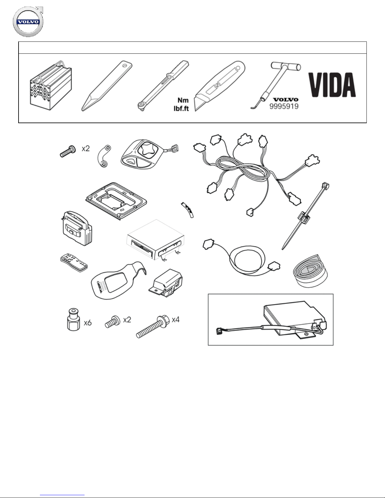
Equipment
A0000162
IMG-
239667
IMG-
239664
IMG-
239980
IMG-
246925
IMG-
242205
R3905015
Installation instructions, accessories
Volvo Car Corporation Gothenburg, Sweden
©
Volvo Car Corporation
Navigation system, RTI- 31260737 - V1.2
Page 2 / 26
Page 3
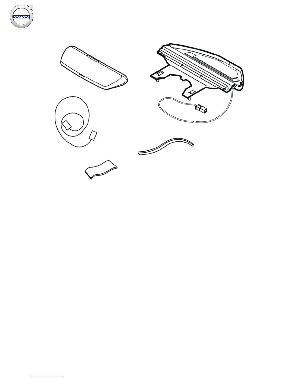
R3903812
Installation instructions, accessories
Volvo Car Corporation Gothenburg, Sweden
©
Volvo Car Corporation
Navigation system, RTI- 31260737 - V1.2
Page 3 / 26
Page 4
INTRODUCTION
Read through all of the instructions before starting installation.
Notifications and warning texts are for your safety and to
minimise the risk of something breaking during installation.
Ensure that all tools stated in the instructions are available
before starting installation.
Certain steps in the instructions are only presented in the form
of images. Explanatory text is also given for more complicated
steps.
In the event of any problems with the instructions or the
accessory, contact your local Volvo dealer.
Note!
This accessory requires software unique to the car.
Note!
For European users, the TMC unit, part number 6849907, can
be purchased separately.
Preparations
1
IMG-
242268
Preparations
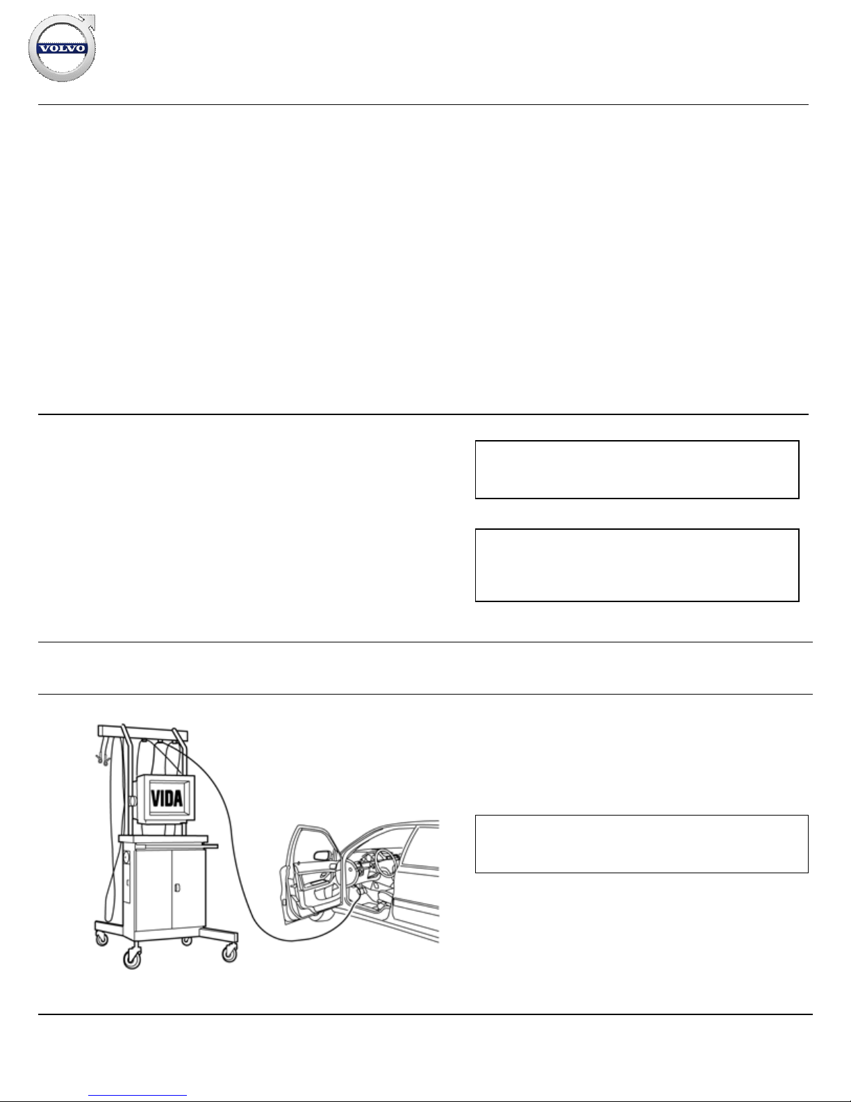
Download the software for the accessory's function
following the service information in VIDA.
Note!
The software must be loaded before installing the accessory.
Installation instructions, accessories
Volvo Car Corporation Gothenburg, Sweden
©
Volvo Car Corporation
Navigation system, RTI- 31260737 - V1.2
Page 4 / 26
Page 5
2
IMG-
332179
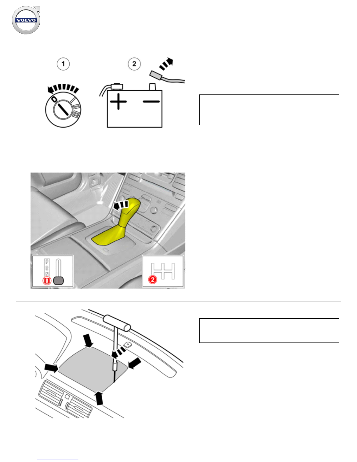
Place the driver's seat in its rearmost position.
Turn the ignition switch to position 0.
Disconnect the battery negative lead
Turn the ignition key to position II, to prevent the steering column
lock engaging.
Note!
Wait at least one minute before unplugging the connectors or
removing other electrical equipment.
3
IMG-
326548
Move the gear selector lever to its rearmost position
4
IMG-
296283
Remove the loudspeaker grille as follows: Insert the special tool
9995919 into the joint between the loudspeaker grille and the
dashboard approximately as illustrated, until it engages.
Twist the tool 90° so that the bent section engages with the
underneath of the loudspeaker grille.
Pull upwards until the loudspeaker grille detaches. The
loudspeaker grille is securely fastened by four clips. Move the
tool closer to the clip to facilitate removal.
Place the loudspeaker grille to one side.
Note!
Do not damage the dashboard.
Installation instructions, accessories
Volvo Car Corporation Gothenburg, Sweden
©
Volvo Car Corporation
Navigation system, RTI- 31260737 - V1.2
Page 5 / 26
Page 6
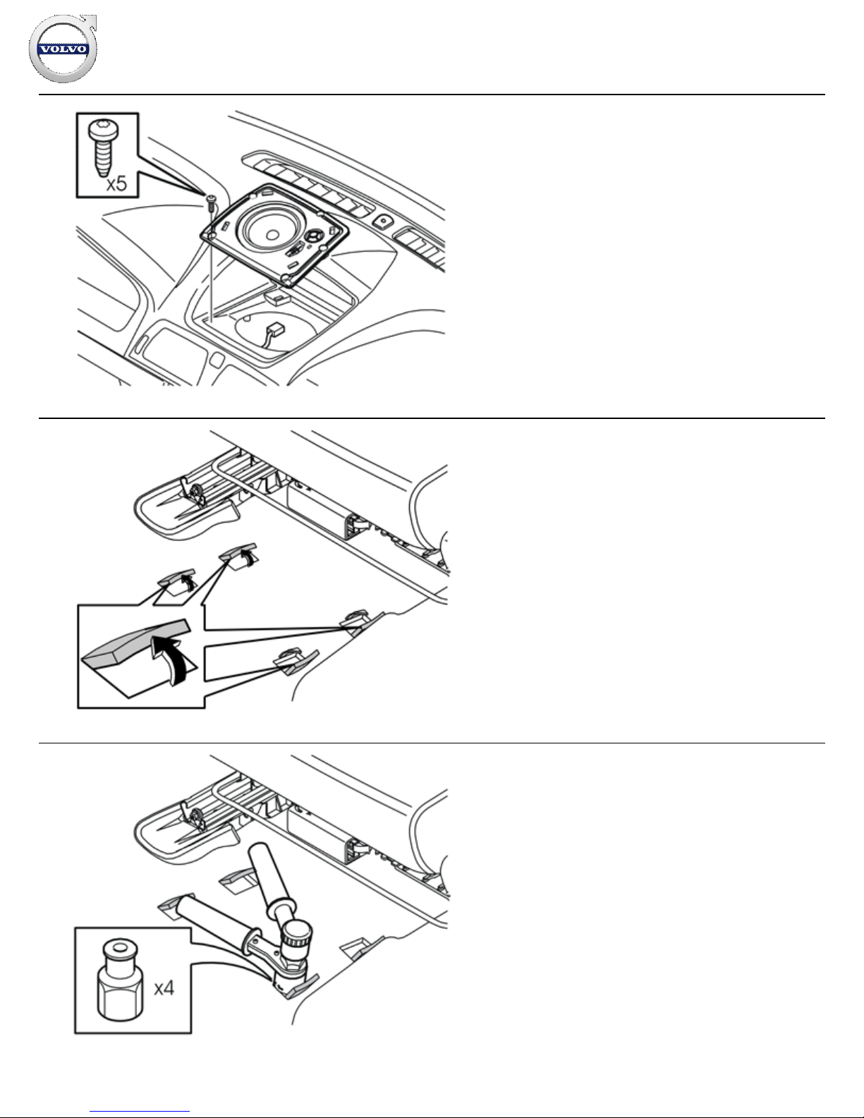
5
R3904128
Applies to cars without centre loudspeakers
Remove the bracket for the loudspeaker grille by removing the
five screws and pulling the grille up from the dashboard.
Applies to cars with a centrally mounted loudspeaker
Remove the five screws in the loudspeaker. Pull the loudspeaker
up slightly from the dashboard and disconnect the connector.
6
R8504212
Bend up the four punched out carpet tabs under the left-hand
front seat.
7
R3903844
Take the four rivet nuts from the kit and install them in the pre
-
punched holes under the carpet tabs.
Take rivet tool
P/N 9512782
and tighten the rivet nuts. If
necessary: Remove the mounting bracket for front-rear seat
adjustment (applies to cars with manual seats).
Installation instructions, accessories
Volvo Car Corporation Gothenburg, Sweden
©
Volvo Car Corporation
Navigation system, RTI- 31260737 - V1.2
Page 6 / 26
Page 7
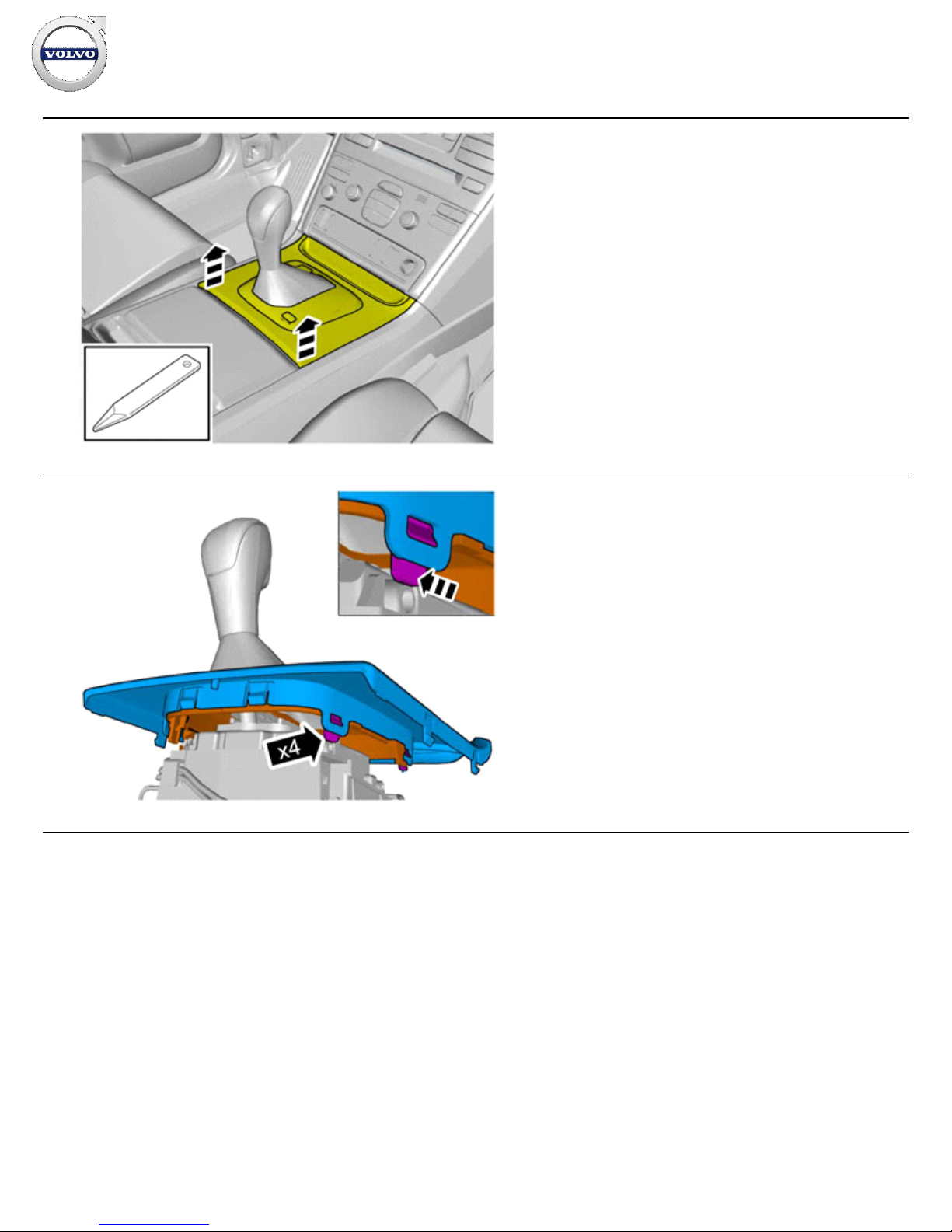
8
IMG-
326553
Use a weatherstrip and pry off the gear selector panel at the
rear edge.
9
IMG-
326554
Press in the catches and remove the panel.
Installation instructions, accessories
Volvo Car Corporation Gothenburg, Sweden
©
Volvo Car Corporation
Navigation system, RTI- 31260737 - V1.2
Page 7 / 26
Page 8
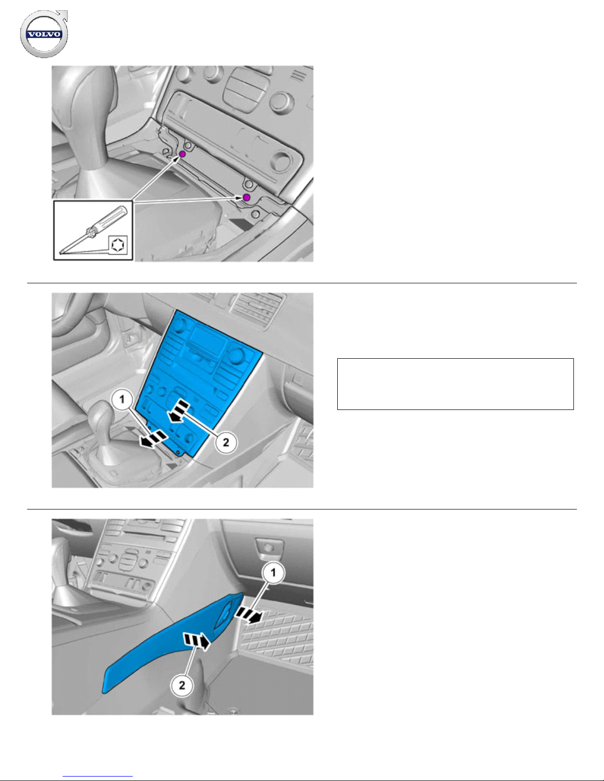
10
IMG-
326558
Remove the two screws.
11
IMG-
326559
Remove the bracket with the A/C panel and radio from the center
console. Pull from the lower edge and then downwards until it
releases from the mounting at the upper edge.
Unplug the connectors
Note!
Do not damage the removed components or the surrounding
panels
12
IMG-
326523
Remove the sound barrier on the right-hand side by first
removing the two screws and then prizing it away at the top
edge.
Repeat the operation on the other side.
Installation instructions, accessories
Volvo Car Corporation Gothenburg, Sweden
©
Volvo Car Corporation
Navigation system, RTI- 31260737 - V1.2
Page 8 / 26
Page 9
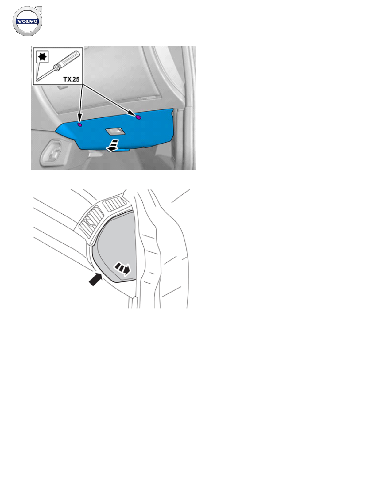
13
IMG-
381786
Remove the screws
Remove the panel.
Repeat the operation on the other side.
14
IMG-
241300
Remove the panel on the right
-hand end of the dashboard.
Does not apply to cars with Volvo On Call (VOC)
Installation instructions, accessories
Volvo Car Corporation Gothenburg, Sweden
©
Volvo Car Corporation
Navigation system, RTI- 31260737 - V1.2
Page 9 / 26
Page 10
15
R8504175
Does not apply to cars with Volvo On Call (VOC)
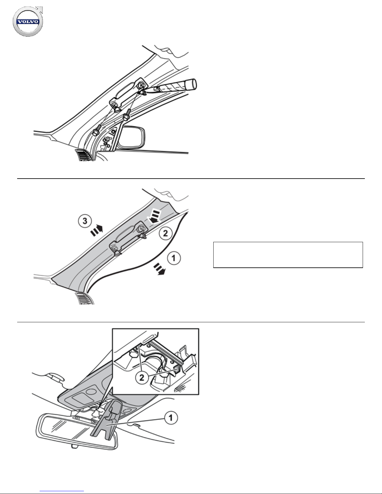
Pry off the covers on the grab handle in the right-hand front door
and remove the screws under them.
16
IMG-
241301
Pull of the weatherstrip (1) for the door at the A-
pillar.
Remove the right
-hand A-post panel by carefully pulling it out by
the upper edge until the clips inside release. Pull it up from the
mounting in the dashboard.
Note!
Do not damage the headlining.
17
R3501441
Fold down the cover (1) by carefully pulling the front edge of the
cover down.
Press the catches (2) together. Pull the front edge of the panel
down and then pull off at the rear edge.
Installation instructions, accessories
Volvo Car Corporation Gothenburg, Sweden
©
Volvo Car Corporation
Navigation system, RTI- 31260737 - V1.2
Page 10 / 26
Page 11
18
R3501449
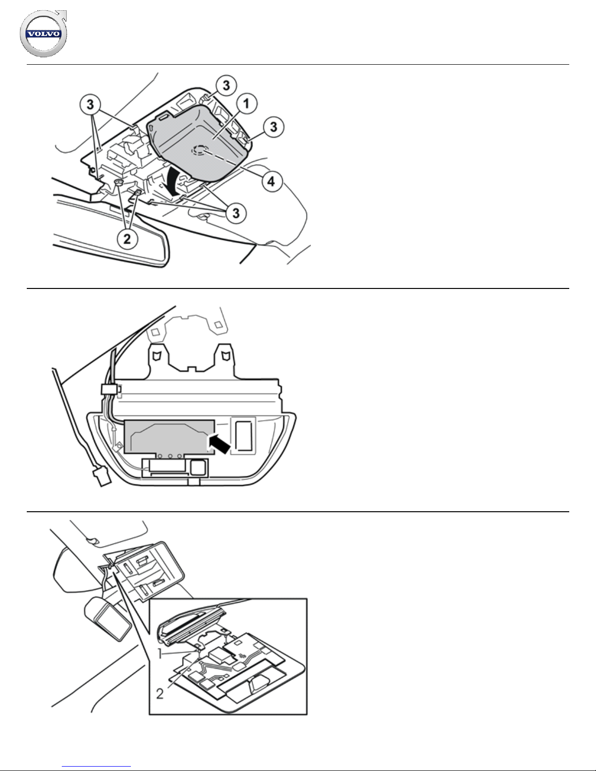
Detach the rear-view mirror and front interior lighting (1) by first
removing the two screws (2) and then pressing in the eight
catches (3) around the interior lighting.
Carefully pull the components downwards and allow them to
hang from their cables. The interior lighting is secured in the roof
by clips (4).
Remove the connector for the rain sensor (if applicable).
19
IMG-
250468
NOTE! When installing the GPS antenna where there is
already a GSM antenna, move the GSM section to the GPS
antenna supplied with the kit. Make sure that the earth
for the screen is correctly positioned when installing.
20
D3902236
Wrap foam tape around the entire cable before installing.
Install the new antenna. Carefully bend the headlining downward
and slide the antenna backward and inwards. Align the antenna
lugs (1) with the grooves in the bracket (2)
Insert the cable on the top of the roof panel's front edge. Pull it
further along, out towards the right-hand A-post so that it is
concealed at the top the headlining.
Reinstall the bracket with rear-view mirror. Tighten the screws
to 10 Nm (7.5 lbf.ft.).
Reinstall the panel and lock using the cover.
If there is a rain sensor, route the cable so that it lies underneath
the antenna. Reinstall the connector.
Installation instructions, accessories
Volvo Car Corporation Gothenburg, Sweden
©
Volvo Car Corporation
Navigation system, RTI- 31260737 - V1.2
Page 11 / 26
Page 12
21
IMG-
250467
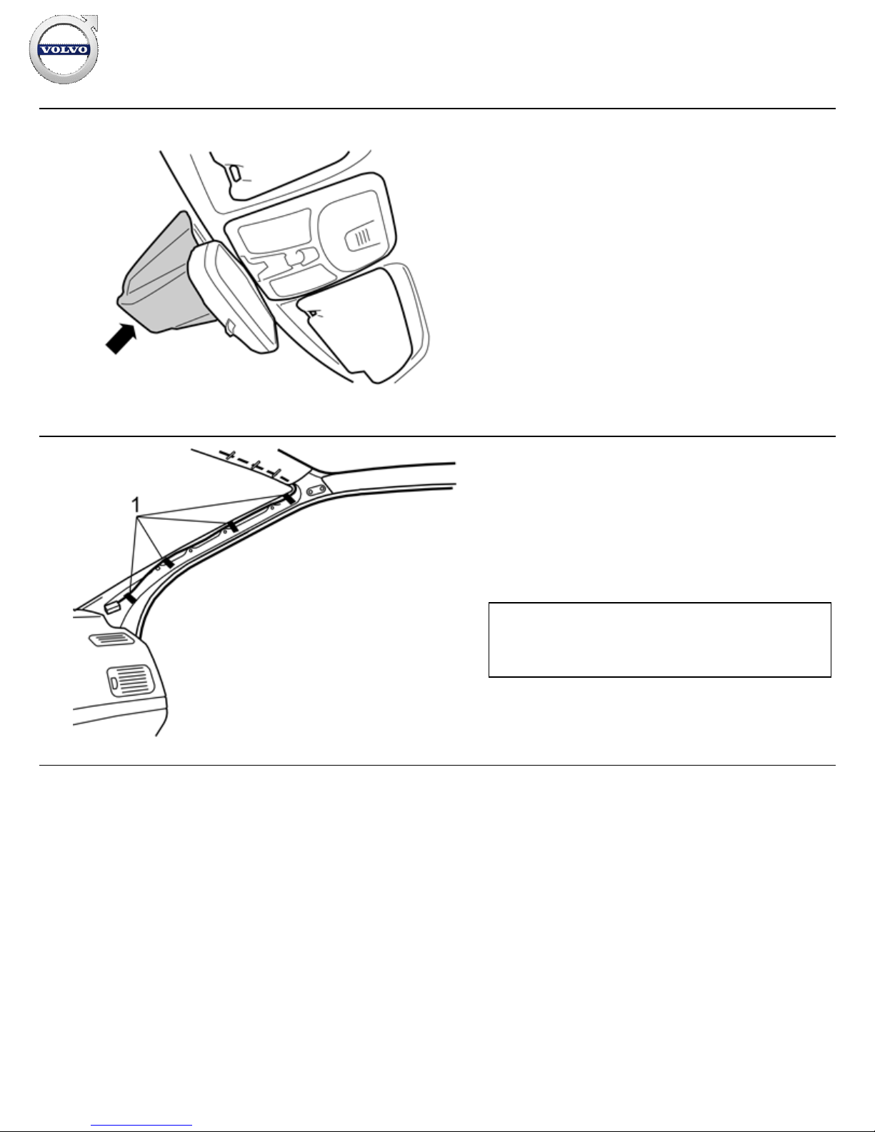
Install the cover over the antenna.
For cars with a rain sensor, use the larger cover from the kit.
For cars without a rain sensor, use the smaller cover from the
kit.
22
R8504164
Route the cable above the headlining, all the way to the A-post.
Route the cable down from the headlining and along the righthand A-post
Tape the cable onto the existing cable harness at points (1).
Warning!
Do not route over the inflatable curtain as this may affect the
function in the event of a collision.
Installation instructions, accessories
Volvo Car Corporation Gothenburg, Sweden
©
Volvo Car Corporation
Navigation system, RTI- 31260737 - V1.2
Page 12 / 26
Page 13
23
IMG-
250470
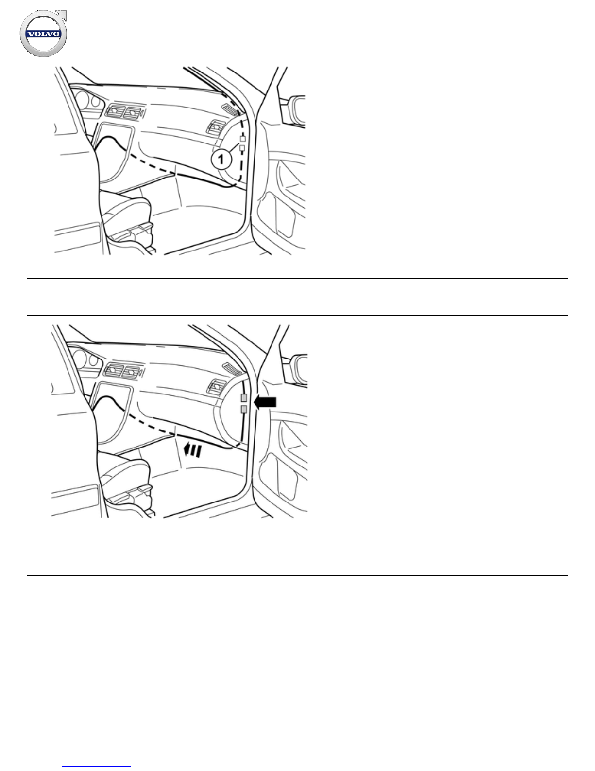
Wrap foam tape around the entire cable before installing
Take the extension cable from the kit. Insert it down between the
A-post and the right-hand side of the dashboard, continue along
the right-hand end of the dashboard and pull out at the front
edge of the floor.
Pull the cable to the left, along the front edge of the floor and up
to the inside of the center console.
Connect both connectors (1) at the A-post to each other.
Wrap foam tape around the connectors to prevent rattling.
Applies to cars with Volvo On Call (VOC)
24
IMG-
393642
Applies to cars with Volvo On Call (VOC)
Locate the joint on the existing antenna cable. Disconnect the
connector, this will not be reused. Tape it up to prevent rattling.
Take the extension cable from the kit. Wrap foam tape around
the entire cable. Connect the cable
Route the cable at the front edge of the floor and on to the
centre console
Applies to all cars
Installation instructions, accessories
Volvo Car Corporation Gothenburg, Sweden
©
Volvo Car Corporation
Navigation system, RTI- 31260737 - V1.2
Page 13 / 26
Page 14
25
IMG-
393650
Applies to all cars
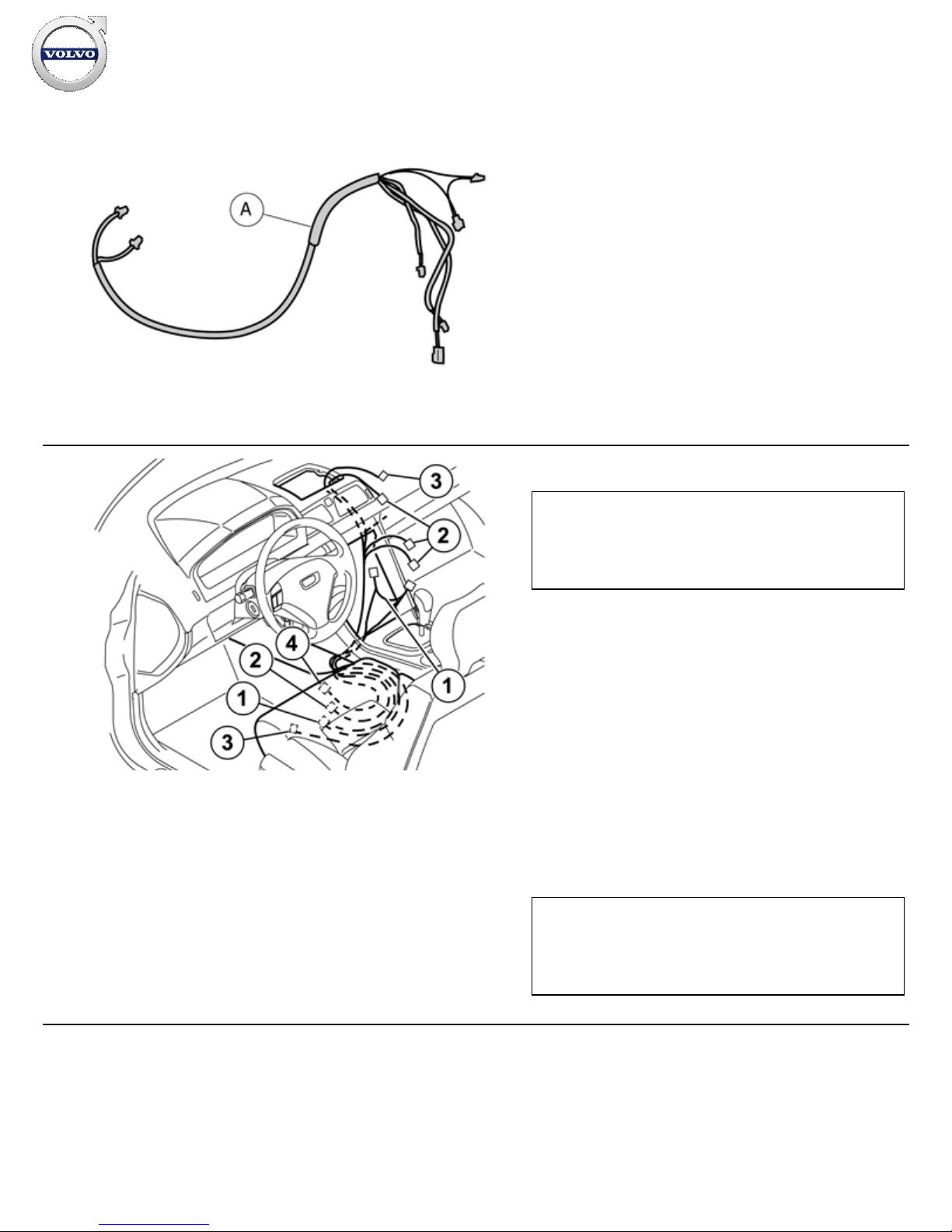
Take the cable harness (A) from the kit.
26
IMG-
251403
Take the two cable harnesses, power supply/fibre optic cable
harness (A) and the cable harness (B) for the display screen
from the kit. Route them up along the air duct on the left
-hand
side of the centre console.
The power supply/fibre optic cable harness (A) is located inside
the centre console.
Pull the cable harnesses backwards, in front of the carpet on the
center console's left-hand side, under the left-hand seat's seat
rail, and out through the carpet join under the seat.
Route the antenna cable (C) the same way as cable harness (A)
to below the seat.
Note!
Do not damage the fibre optic cables. They must not be bent to
a radius less than 30 mm (1 11/64") as they can damage and
affect the function of the system.
Note!
In cases where the TMC cable (Europe) requires to be routed
in the same way as cable harness (1). The double connection
must be connected to IAM.
Installation instructions, accessories
Volvo Car Corporation Gothenburg, Sweden
©
Volvo Car Corporation
Navigation system, RTI- 31260737 - V1.2
Page 14 / 26
Page 15
27
IMG-
268410
28
IMG-
241303
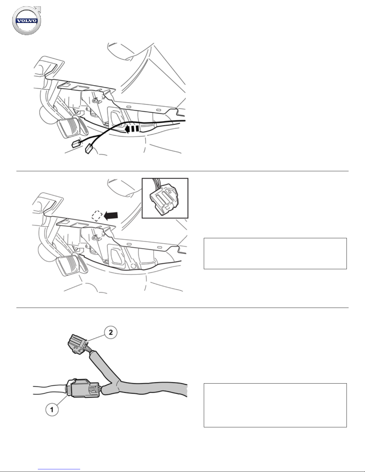
Take the cable with the two 4 pin connectors and route
forward on the driver's side
Locate the 4 pin, grey connector for the power supply. It is
secured on the thick cable harness under the dashboard on the
driver's side.
Note!
The pre
-routed connector is already connected on certain
versions
29
IMG-
268502
Connect the cable harness to the existing connector (1).
Wrap a piece of foam tape around the connected connectors
and cut off the excess.
Install the connector (2) on the car's existing cable harness
using a cable tie.
Note!
The pre
-routed connector is already connected on certain
versions. In such a case, disconnect it and connect both
connectors from the new cable harness. Wrap a piece of foam
tape around the connectors.
Installation instructions, accessories
Volvo Car Corporation Gothenburg, Sweden
©
Volvo Car Corporation
Navigation system, RTI- 31260737 - V1.2
Page 15 / 26
Page 16
30
Reinstall the A post panel.
Tighten the grab handle to
10 Nm (7.5 lbf. ft.)
and reinstall
the covers.
Reinstall the rubber trim in the right
-hand front door.
Reinstall the panel on the dashboard end face.
Reinstall the soundproofing panel on the right-hand side.
31
IMG-
250476
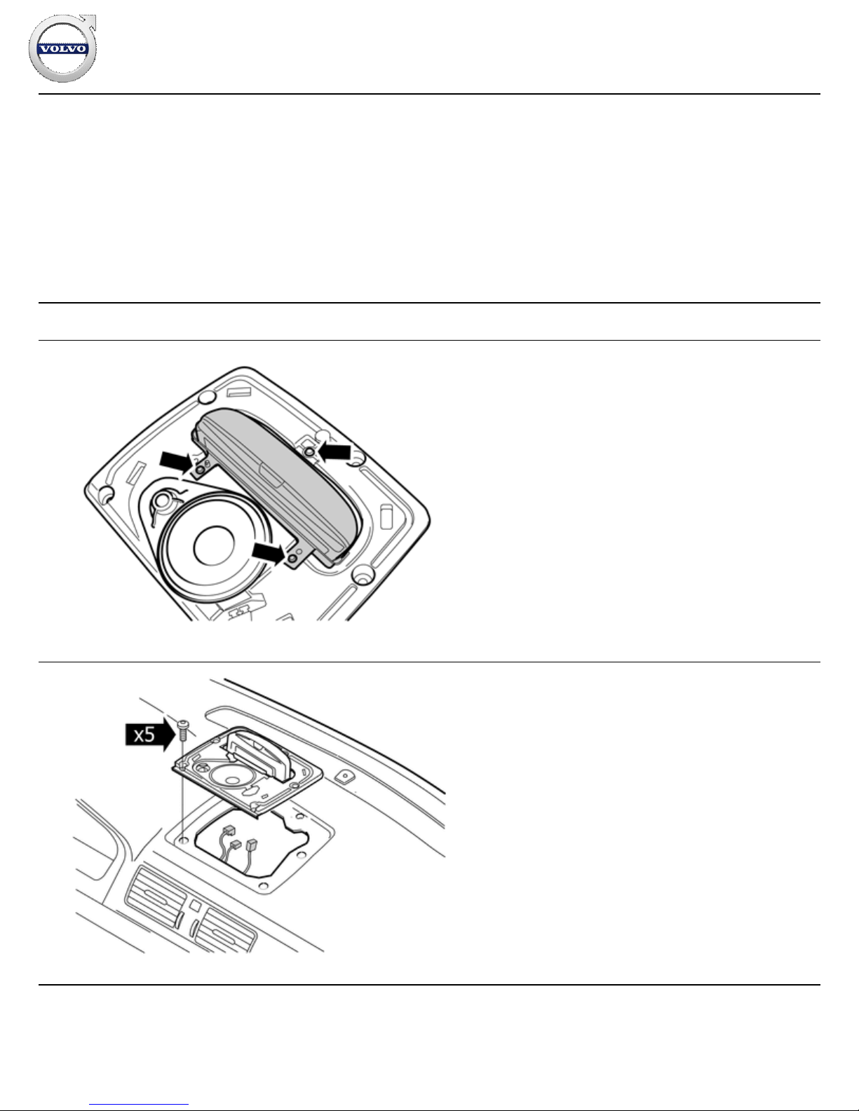
Install the bracket for the display screen by moving the screen
unit up in the bracket from underneath.
Tighten the display screen unit by the bracket using screws from
the kit.
32
IMG-
393655
Connect the 2 cables from the Multimedia Module (MMM) to the
display screen.
Install the display screen with the bracket in the dashboard. Use
the existing screws.
Take the new loudspeaker grille from the kit and press it into the
dashboard.
Installation instructions, accessories
Volvo Car Corporation Gothenburg, Sweden
©
Volvo Car Corporation
Navigation system, RTI- 31260737 - V1.2
Page 16 / 26
Page 17
33
IMG-
250477
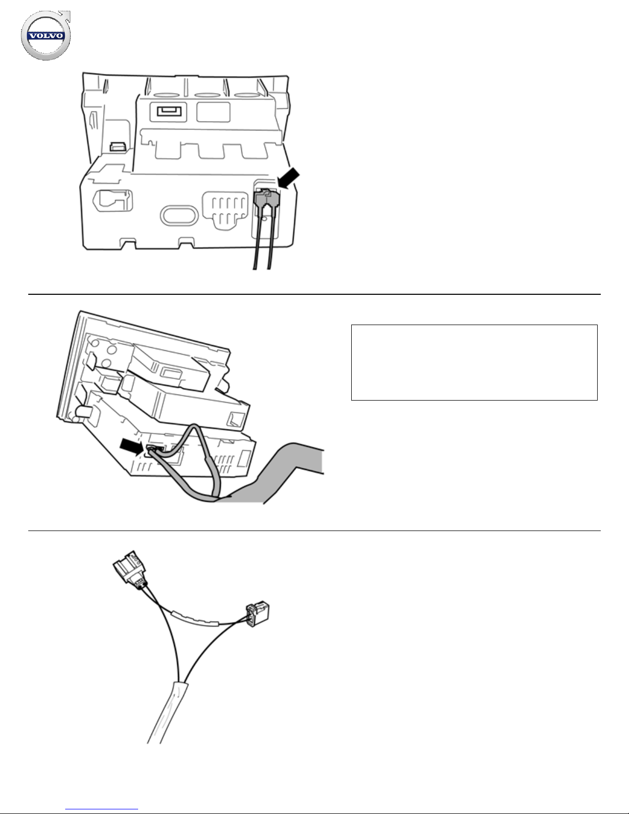
Connect the TMC cable (Europe) as illustrated.
Connect the TMC wiring between IAM and the existing connector
in the car's cable harness.
34
IMG-
250478
Note!
It is important that the wiring is connected to the Integrated
Audio Module (IAM) and not the Infotainment Control Module
(ICM). Do not mix up the fibre optic connections in the existing
cable network.
35
IMG-
250479
Connect the fibre optic cables between the Integrated Audio
Module (IAM) and existing MOST cable.
Installation instructions, accessories
Volvo Car Corporation Gothenburg, Sweden
©
Volvo Car Corporation
Navigation system, RTI- 31260737 - V1.2
Page 17 / 26
Page 18
36
IMG-
250480
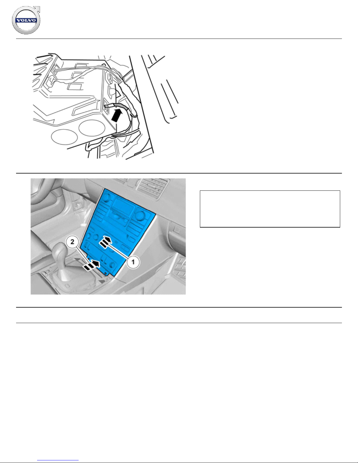
Take the bend protection from the kit and attach it with tape as
illustrated. The bend protection is to prevent the fiber optic cable
from bending too much, being damaged and risking malfunction
of the accessory.
37
IMG-
326564
Plug in the connectors.
Reinstall the radio/A/C unit by first hooking the upper edge
into place. Then press upwards and angle in the lower section.
If the radio/A/C unit does not fit at the rear edge, check that
no cables have been trapped.
Reinstall the screws
Note!
When reinstalling the centre console, the fibre optic cable to
MOST must be positioned so that it does not get trapped when
the centre console is reinstalled.
Installation instructions, accessories
Volvo Car Corporation Gothenburg, Sweden
©
Volvo Car Corporation
Navigation system, RTI- 31260737 - V1.2
Page 18 / 26
Page 19
38
R3903835
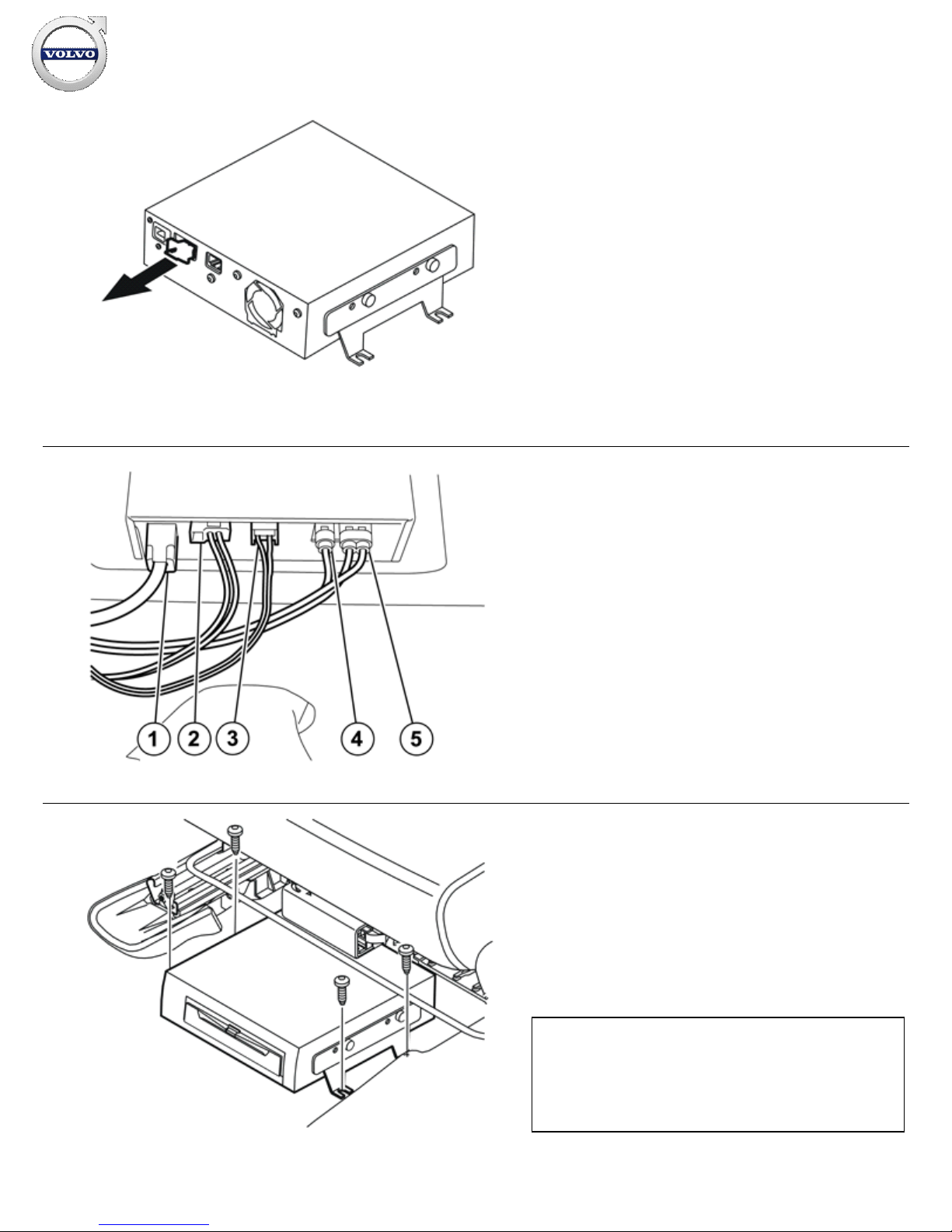
Take the Multimedia Module (MMM) from the kit and remove the
protective plug from the connector to the fibre optic cable
connection.
39
IMG-
250481
Connect the pre-routed cables to the Multimedia Module
(MMM)
the cable (1) for the display screen.
cable (2) to the car's fiber optic cable system.
cable (3) to the power supply.
cable (4) to the Global Positioning System (GPS) antenna.
cable (5) to TMC (Europe).
Secure the cable excess for the GPS antenna in a suitable
location.
40
R3903837
Take four screws from the kit, place the Multimedia Module
(MMM) mounting brackets above the rivet nuts and tighten the
unit.
Conceal the cables under the carpet at the rear of the Multimedia
Module (MMM).
Bend the carpet tabs back over the screws.
Note!
Do not damage the fiber optic cables. They must not be bent to
a radius less than 30mm (1 11/64") as they may become
damaged and affect the function of the Multimedia Module
(MMM).
Installation instructions, accessories
Volvo Car Corporation Gothenburg, Sweden
©
Volvo Car Corporation
Navigation system, RTI- 31260737 - V1.2
Page 19 / 26
Page 20
41
IMG-
308584
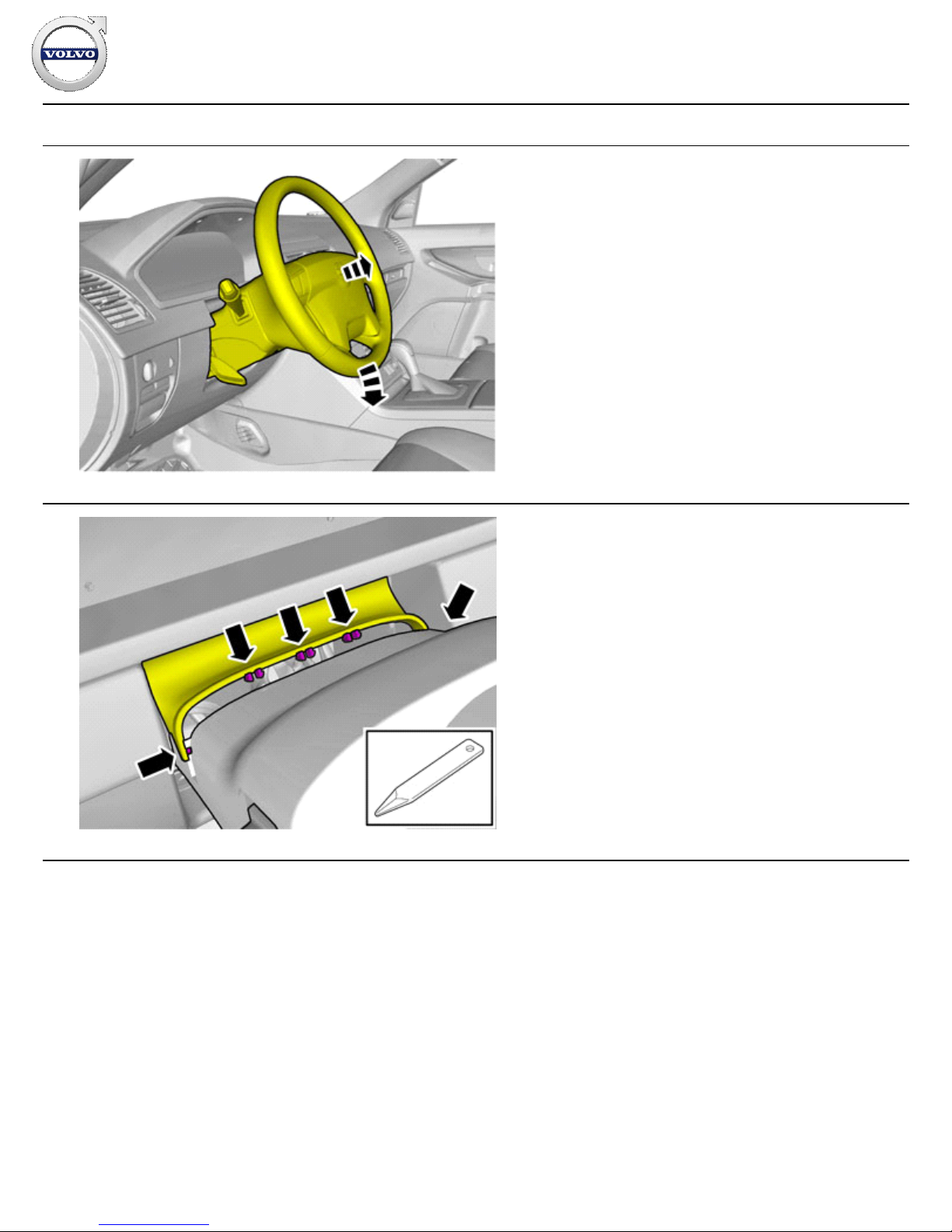
Position the steering wheel in its lowest and rearmost position.
42
IMG-
351381
Carefully pry off the protection using a plastic weatherstrip tool.
Installation instructions, accessories
Volvo Car Corporation Gothenburg, Sweden
©
Volvo Car Corporation
Navigation system, RTI- 31260737 - V1.2
Page 20 / 26
Page 21
43
IMG-
351388
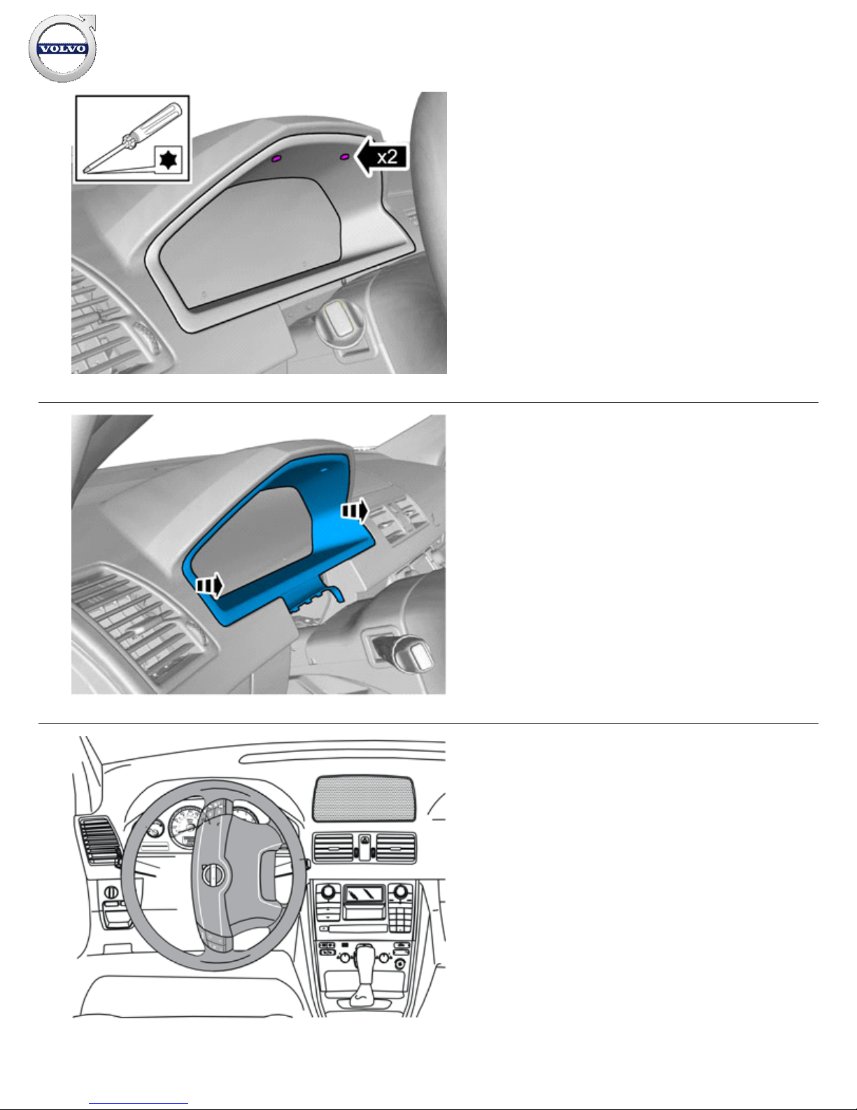
Remove the screws.
44
IMG-
308587
Remove the surround for the combined instrument panel
45
R6400815
Turn the steering wheel 90º to the position shown in the
illustration and so that the two holes on the back side are
accessible.
Installation instructions, accessories
Volvo Car Corporation Gothenburg, Sweden
©
Volvo Car Corporation
Navigation system, RTI- 31260737 - V1.2
Page 21 / 26
Page 22
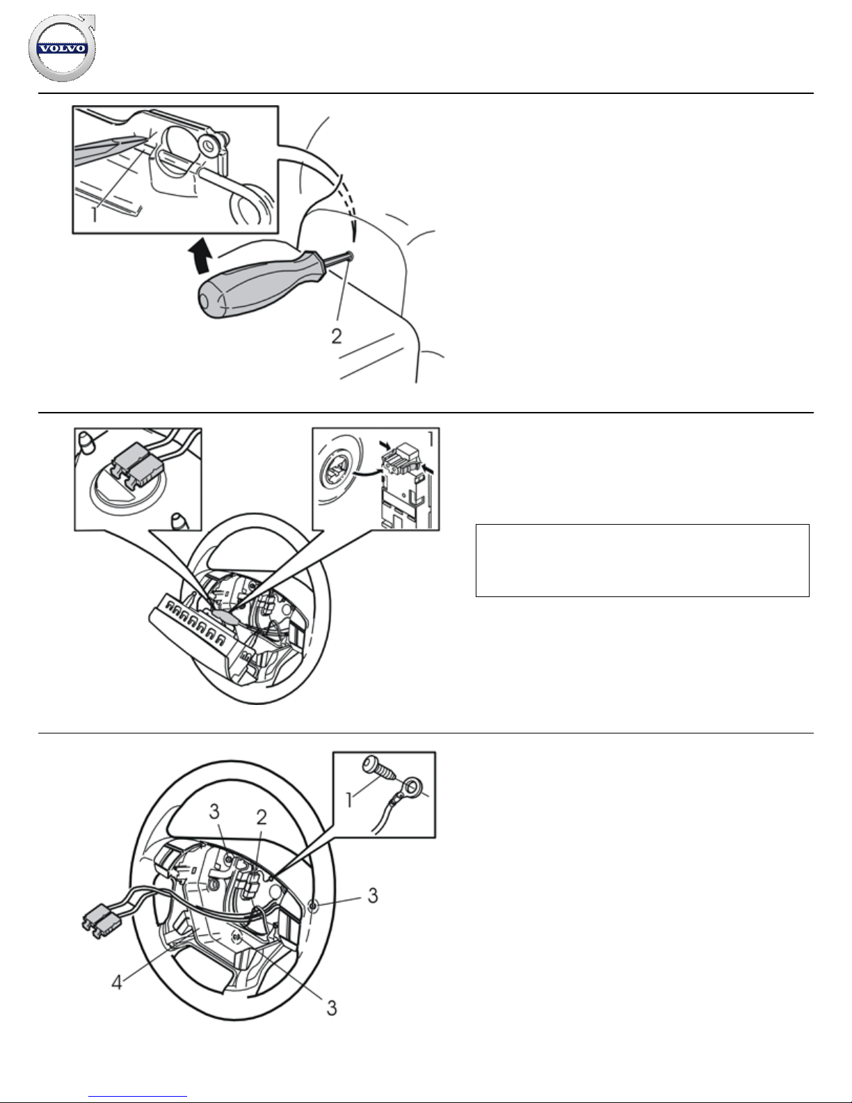
46
M6400670
Insert a screwdriver in the hole along the rear edge of the
steering wheel perpendicular to the rear surface of the steering
wheel.
Insert the screwdriver as far as possible to find the end of the
locking spring (1).
Place the end of the screwdriver on the top of the locking spring.
Move the screwdriver upwards towards the upper edge of the
hole (2) until the spring releases and one side of the steering
wheel module detaches from the mounting.
Turn the steering wheel 180º and repeat the operation on the
other side.
Turn the steering wheel to a neutral position.
47
R6400818
Fold the steering wheel module out
Unplug the two connectors (1) to the airbag transmitter cables.
Place the steering wheel module to one side.
Note!
The connectors are tightly secured. However, tools must not
be used when removing.
48
R6400819
Remove:
the screw (1) and detach the ground lead.
the horn connector (2) and keypads.
the three screws (3) and lift out the horn ring (4).
Installation instructions, accessories
Volvo Car Corporation Gothenburg, Sweden
©
Volvo Car Corporation
Navigation system, RTI- 31260737 - V1.2
Page 22 / 26
Page 23
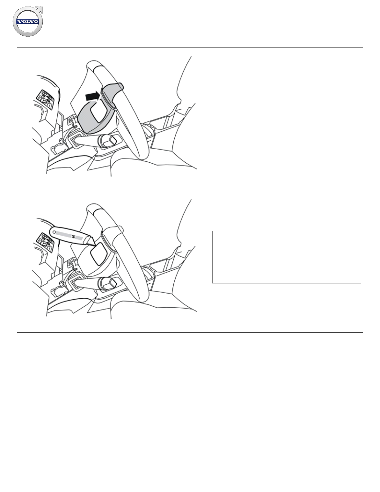
49
R3904964
Turn the steering wheel to the left so that the right-hand side of
the steering wheel points to the left.
Take the cutting template from the kit and secure it to the right
-
hand side of the steering wheel as illustrated.
Attach the template using a tie strap.
50
R3904965
Set the steering wheel in a suitable position and cut-out following
the template. Use a small knife.
Note!
When cutting, make sure to hold the knife so that the cuts are
perpendicular to the back side of the steering wheel. This will
reduce the risk of cutting a hole that is too large since the edge
around the keypad is only a few millimetres larger than the
keypad itself.
Installation instructions, accessories
Volvo Car Corporation Gothenburg, Sweden
©
Volvo Car Corporation
Navigation system, RTI- 31260737 - V1.2
Page 23 / 26
Page 24
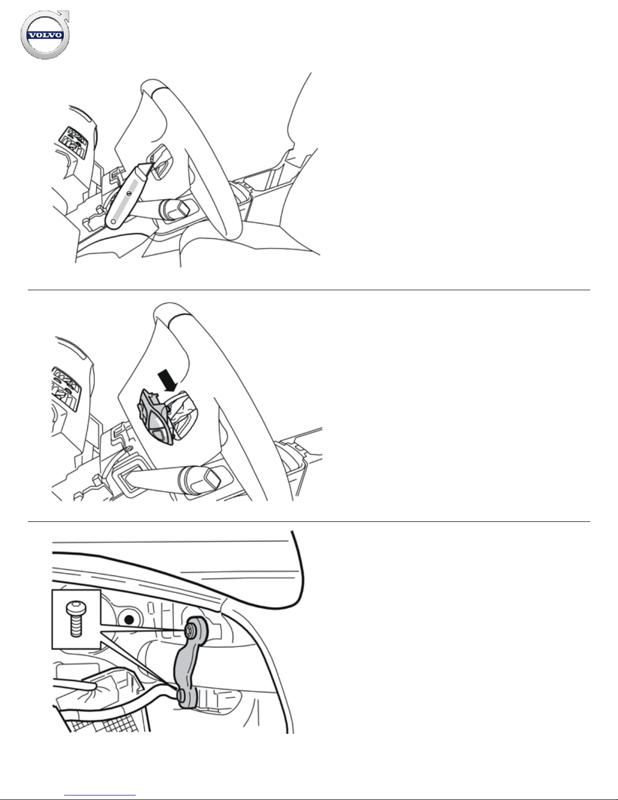
51
R3904966
Cut away some of the material on the back side of the steering
wheel spoke.
Test and cut until the keypad fits properly.
52
R3904967
Remove the keypad, two screws and clamp from the kit.
Ensure that the cable is underneath the steering wheel spoke
(When the steering wheel is straight).
Insert the keypad into the hole in the steering wheel with the text
on the keypad facing up. Press until it connects securely against
the steering column cover.
53
M3903757
Install the screws and attach the keypad with the clamp around
the steering wheel spoke.
Installation instructions, accessories
Volvo Car Corporation Gothenburg, Sweden
©
Volvo Car Corporation
Navigation system, RTI- 31260737 - V1.2
Page 24 / 26
Page 25
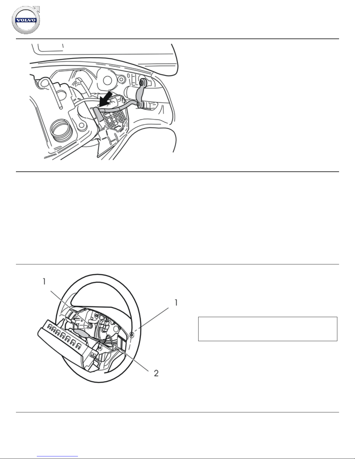
54
M3903758
Position the horn ring and position it as illustrated.
Plug in the installed keypad connector to the terminal on the back
side of the keypad on the right-hand side of the horn ring. The
cable from the installed keypad is very short and it is not easy to
plug into the connector.
55
Reinstall the horn. Ensure that the three springs are in place and
check that the ground lead is not trapped.
Tighten the screws alternately to 6.5 Nm (5 lbf.ft.).
Reinstall the ground lead. Tighten.
Plug in the horn connector and keypads.
Check the function of the horn ring by pressing around the entire
edge.
56
R6400820
Check that the two springs (1) are in position
Position the steering wheel module and press the two airbag
transmitter cable connectors firmly in place.
Insert the two lugs on the back side of the steering wheel
module into the two springs and make sure the transmitter cables
are not obstructed.
Press the steering wheel module firmly into its mountings. Two
clearly audible clicks should be heard.
Reinstall the surround for the combined instrument panel and the
steering wheel cover.
Note!
The cables must be routed through the existing holder (2).
Installation instructions, accessories
Volvo Car Corporation Gothenburg, Sweden
©
Volvo Car Corporation
Navigation system, RTI- 31260737 - V1.2
Page 25 / 26
Page 26
57
IMG-
336901
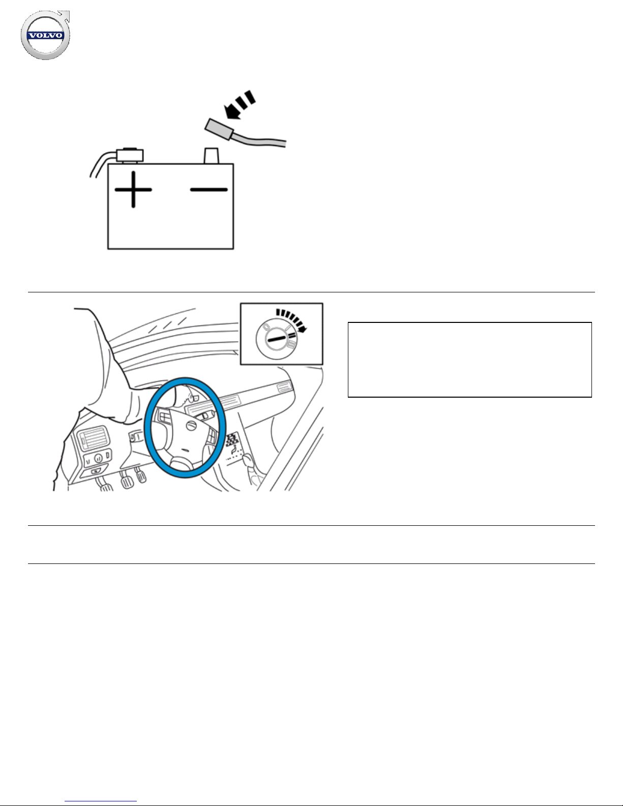
Reconnect the battery negative lead
58
IMG-
336904
Set the ignition key to position II.
Warning!
When the ignition is to be switched on for the first time after the
battery has been disconnected, this must be done whilst by
standing outside the vehicle, stretching your arm in and
avoiding the working area for the airbags
59
Reinstall the detached components in reverse order.
Installation instructions, accessories
Volvo Car Corporation Gothenburg, Sweden
©
Volvo Car Corporation
Navigation system, RTI- 31260737 - V1.2
Page 26 / 26
 Loading...