

Volvo 240, 260 Service Manual

Service
Manual
Repairs
and maintenance
Section
I
(87)
Air
conditioning
Volvos ar8 sold in vercions adapted
for differsnt matksF.
These adaptions
d€psnd on many factoB
including legal,
taxation
and
mark€t r€ouir€m€nts.
Thb manual
may thersforB show illustrctions and text
which do not apply
to
cars
in
your
country.
Order No TP 30161/1
This manual suD€rcedes:
IP 11633/1
24o Air conditioning
fP 1 124A/1
260 Air conditioninq
fP
115A4/1 240 Air conditionina
{USA,/Canaoa,
TP 11412/2 260 Ait @Nitionins
{USA,/Canada}
We ressrv€ the right to make alter8rions

Contents
Specifications
Special tools
General
repair instructions
Damaqed caused by dirt. moisture etc ................
Receiver/Dryer..........
Lubricating oil
l']srallirg
new system
1eakase ................
Safety
preca
utions ....
Faulttracing
Modificatio ns th roug hout the
years
. . . .
Draining refrigerant
Filling relrigerant
Leadtest
............
York
compressor
(24O
petrol/gasoline)
B 20 enqrnes
B21engines.........
Oil level check
Clutch
replacemenr
(rn
car) ..........
Disassemby assembly
Sankyo compressor
{240
Diesel)
Removing fifling bell
adjusrmenr
Replacement
(compressor
removed):
C'urch.
pulley.
cabon seal ................................
Bearing. ragnet
VaLveplate .............
Delco compressor
{6-cyl.
petrol/gasoline}
Femoving
-fittrng -
bek adjustmenl ..
Replacrng: clutch.
pulley.
bea ng. magnet
Disassembly-
asserbly ..
Evaporator, replacemem
Evaporator
thermostat, replacement, modification .........
Inspeflron ............... .......
Expansion valve
(near
evaporator),
replacemem
.......
Expansion valve - suction dischaage valve on dryer, re-
pracemem...........
Condenser, replacement . . . . . . . . . . . . . . . . . . . . . . . . . . . . . . . .
Receiver/dryer,dryingage
(desiccant)
replacement
Eetrigerant hoses
Heater control valve, checking .....................
AC compensation
{idle
speed compensation)
Operation Page
2
4
6
7
7
23
26
27
2A
33
34
34
39
40
41
42
50
52
54
55
58
60
60
63
70
11
72
13
B
1-21
a 22-27
c 1-3
c 4,12
c 16-20
c2144
Dt 5
D 6-24
D624
D 26-29
E 4-5
E645
F 1-a
F 9-15
F 1 6-20
G
1-5
Ht 5
J14
K]6
't2
21
56
57
L'I
Carburetted engines .............. N 1-5
Injected engines .................. N6-16
\Mring
diagrams:
240,1975-1977
260, t915 1517
240,260, t97I
240,260, 1980
240, 260, 1981-
68
69
Index
page
74
Group 87 Air conditioning
Refrigerant, type........
quantity
197F1978
1979- .... ...........
1980-..........
Specifications
Specifications
Perfomance test, see
page
2l
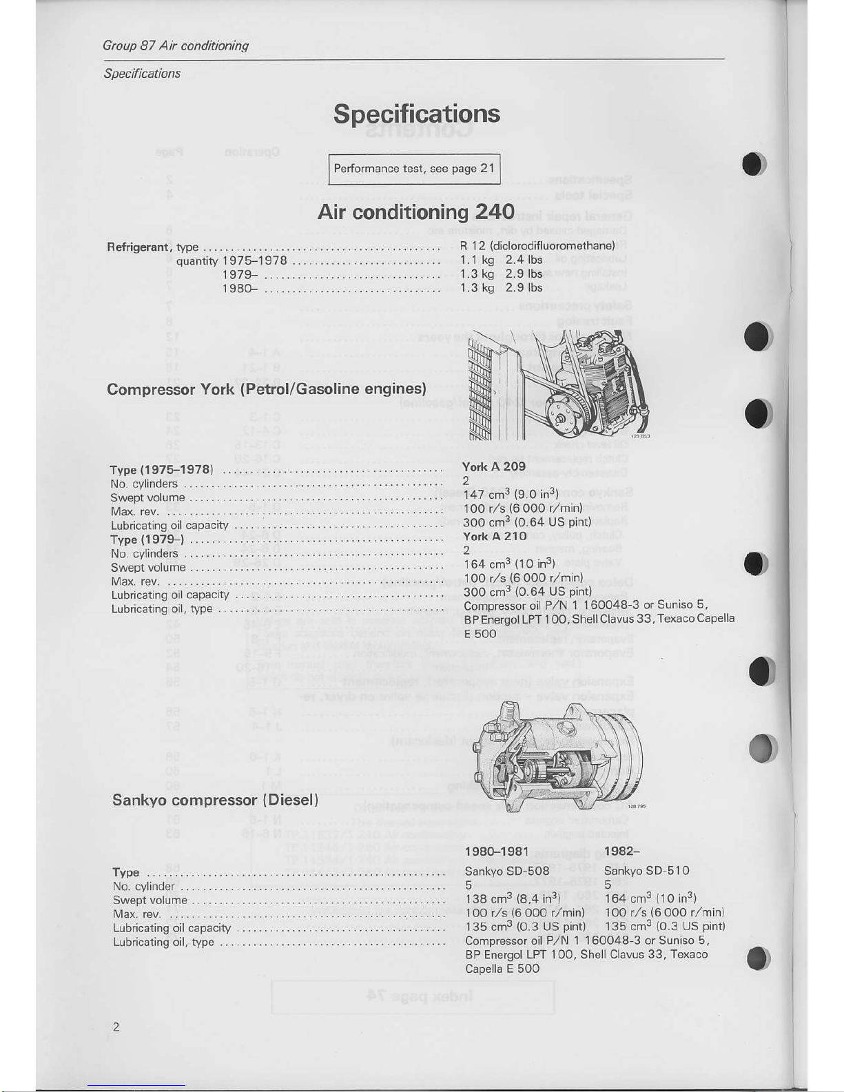
Air
conditioning
24O
Compressor York
(Petrol/Gasoline
engines)
Sankyo
compressor
(Diesel)
York A
209
2
147 cm3
(9.0
in3)
l OO r,/s
(6
OOO r,/min)
3oo cm3
(0.64
us
pint)
York
A 21o
2
164 cm3
(10
in3)
100 r/s
{6
ooo r,hin)
300 cm3
{0.64
us
pint)
compressor
oil P,/N |
160048-3 or Suniso
5,
BP Energol LPT
1 OO, Shell Clavus
33, Tex6co
Capella
E 500
R 1 2
(diclorodif
luoromethanel
1.1 kg 2.4lbs
1.3 ks
2.9lbs
1.3 ks
2.9 lbs
1980-1941
Sankyo SD-508
5
138
cm3
{8,4
in3)
Type
(1975-1979)
No. cylinderc
Swepivolume.....,,,,,,
Max. rev. ..,
Lubricatng oil
capacity
Type
{1979-}
No. cylinderc
Sweplvolume...........
tMax.
rev.
.............
Lubncating oil capacity
Lubricaling
oil. wpe
Type . . . . . . . . . . . . . . . . . .
No. cylinder .............
Swepi vo|ume...........
l!43x. rev. ...............
Lubricating oil capaciry
Lub cating oil, typ€
1942Sankyo SD 5lO
5
164 cm3
(10
in3)
l oo r,/s
(6
000
r/min) 1oo r,/s
(6
ooo r/min)
135 cm3
{o.3
uS
pintt
135 cm3
{0.3
us
pintl
Compressor
oil P,/N 1 1 60048 3 or Suniso 5,
BP EneEol LPT 100, Shellclavus
33, Texaco
Capella E 5OO
Group 87 Air conditioning
Spec if
icationt 2 40, 260
Pulleys,
engine crankshaft
{outeFinner)
817-B 23
...........
Unions, expansion
valve
pressurc
equalizing
pipe
expans|on
valve
expansion valve
hose
evaporator
hose
condense' ..
rcceiver/dryet
......
conpressor
YoA 209,/21O
..........
Sankyo
SD5O8. SDsIO ...........
Compressor,
{Yoft
2O9l21
0)
cylinder
block ... . .
bottom cover
rear beanng
cover
conrcdbolts....
oil
prug.................
Comprcssor
clutch, cenrer
bo|t ...............
Compressor,
Sankyo
cyhnder block
searerreta,ner.....
oil
p1u9...
.................
varve
pdte
.......
.......
Compressor
clurch.
uenrre boll ...........
Tightening
torques
Nm
6-10
't7
30
30
30
11
25
30
30
20-30
20-30
20
20
5
25-30
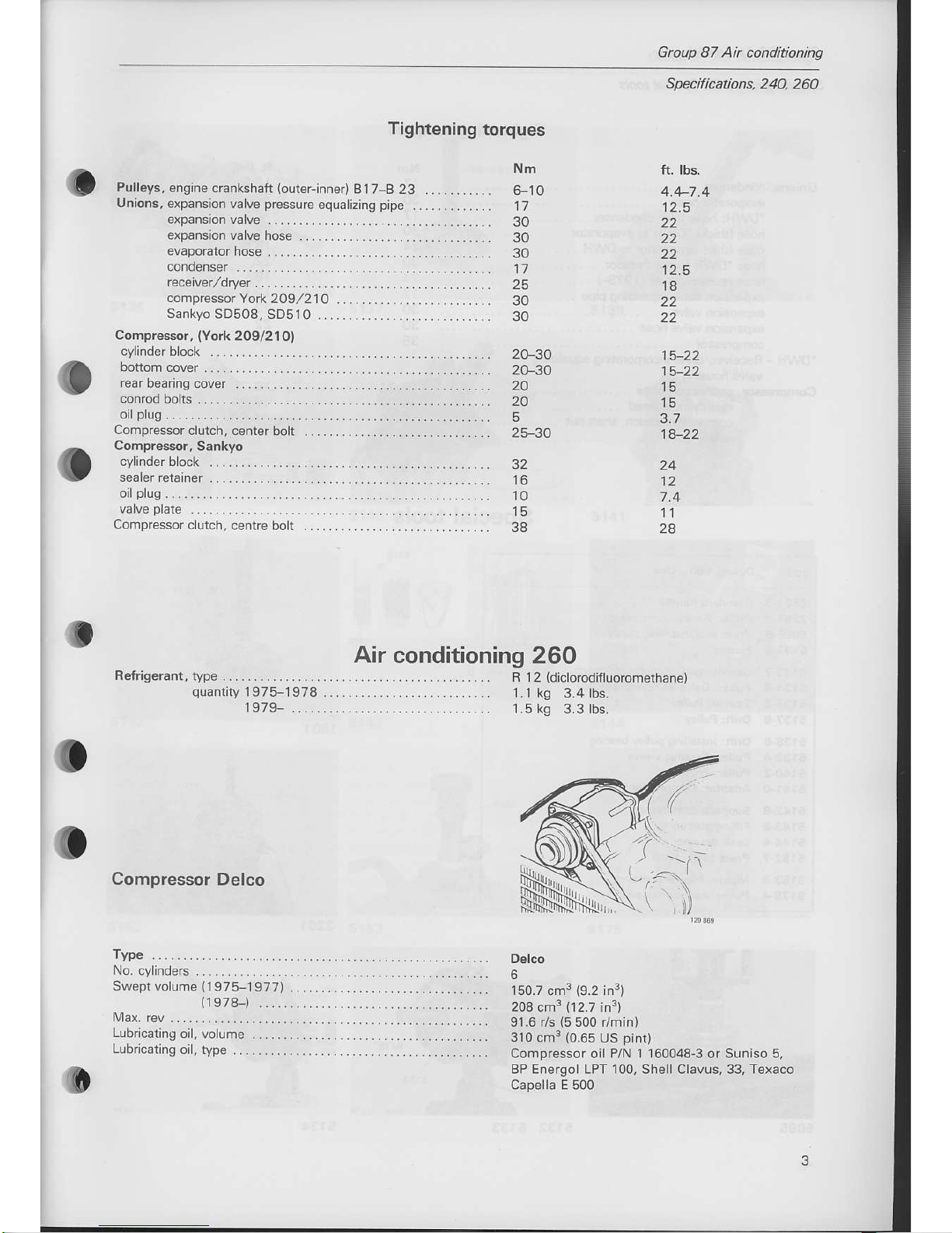
Air conditioning
260
32
10
38
ft.
lbs.
4.4-7.4
12.5
22
22
22
12.5
18
22
22
15-22
15-22
15
3.7
1822
24
12
7.4
1l
2A
Refrigerant,
iype
B 1 2
(diclorodifl
uoromethane)
1.1 kg
3.4 lbs.
1.5 kg 3.3 lbs.
1975-1978
1979-
Compressor Delco
Delco
6
150.7
cm3
{9.2
in3}
208
cm3
(12.7
in3)
91.6 r/s
{5
500 r/min)
310 cm3
(0.65
US
pint)
Compressor oil P/N
'l
160048-3 or Suniso 5,
BP Energol LPT 100, Shell Clavus, 33, Texaco
Capella E 500
Swept volume
(1975-1
977)
(1978-)
Lubricating
oil, volume
Lubdcating
oil, type

Gtoup 87 Air conditioning
Unions, co'1denser
ev.poraror
hose
'DWH
hos. ftom conder
hose
(rhick)
'DWH
to evdporator
hose lrhin) evdporalor
ro DWF ..
hose'DWH rc comprcsso
nose ec€ver'dryer
11979-) ...
..
expanson
varve equdlD
T
pip"
. .......
erPdnsron
valva
expanspr
vdNe nose .. ...
cofprcssor
.. ....
'DWH
-
Receiver./dryer
incorporating equalizing
vaMe nous ng
Compressor,
conreclio1
plale
... ..........
rca.
"yt,nder
5ead .....
comprcssor
culch. shaft nut
............
Specifications 260, Special tools
999
Tightening
torques
1l
30
't7
30
24
30
24
17
30
30
35
1A-34
26-34
19
35
14-19
ft. lbs.
22
12.5
22
t8
22
18
12.5
22
22
26
10-25
19-25
14 26
10-14
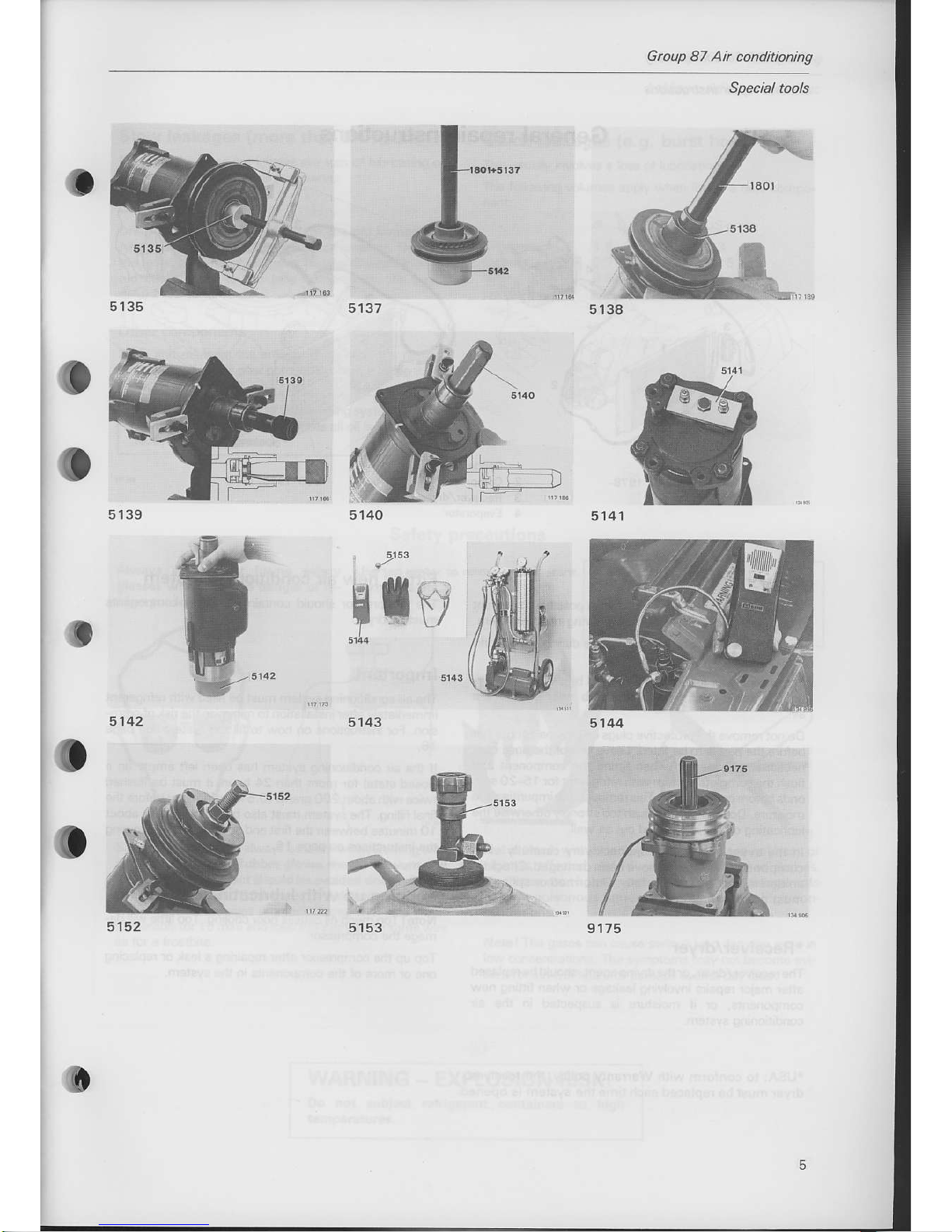
Special
tools
1801-3 Siandard
handle
2261-9 Pulleri Sankyo
compfessor
5085-9
Press tool: nstalLing
pulleY
5133'7
Counterhold:
compressor cluich
5134-5
Puller: DeLco compressor
pulley
5!35-2 Spacer:
Pulley
5137-a
orifr Pu ley
5138-6 Drift:
Installing
pulley
beanng
5139-4
Putler; Ceramic
sleeve
5140-2
Puller: Front sea
5141-0
Adaptor: Compressor
5142-a
Suppon:
compressor
5143-6
Filling station
5'lil4,4 Leak detecror
5152-7
Pre$ tool:
c utch
5153-5
Nipple:iree on
cont€lner
9175-4
Puller: compressor
seal
1801
2261
o
Gtoup 87 Air conditioning
Special tools
5140
f
tri
Group 87
Air conditioning
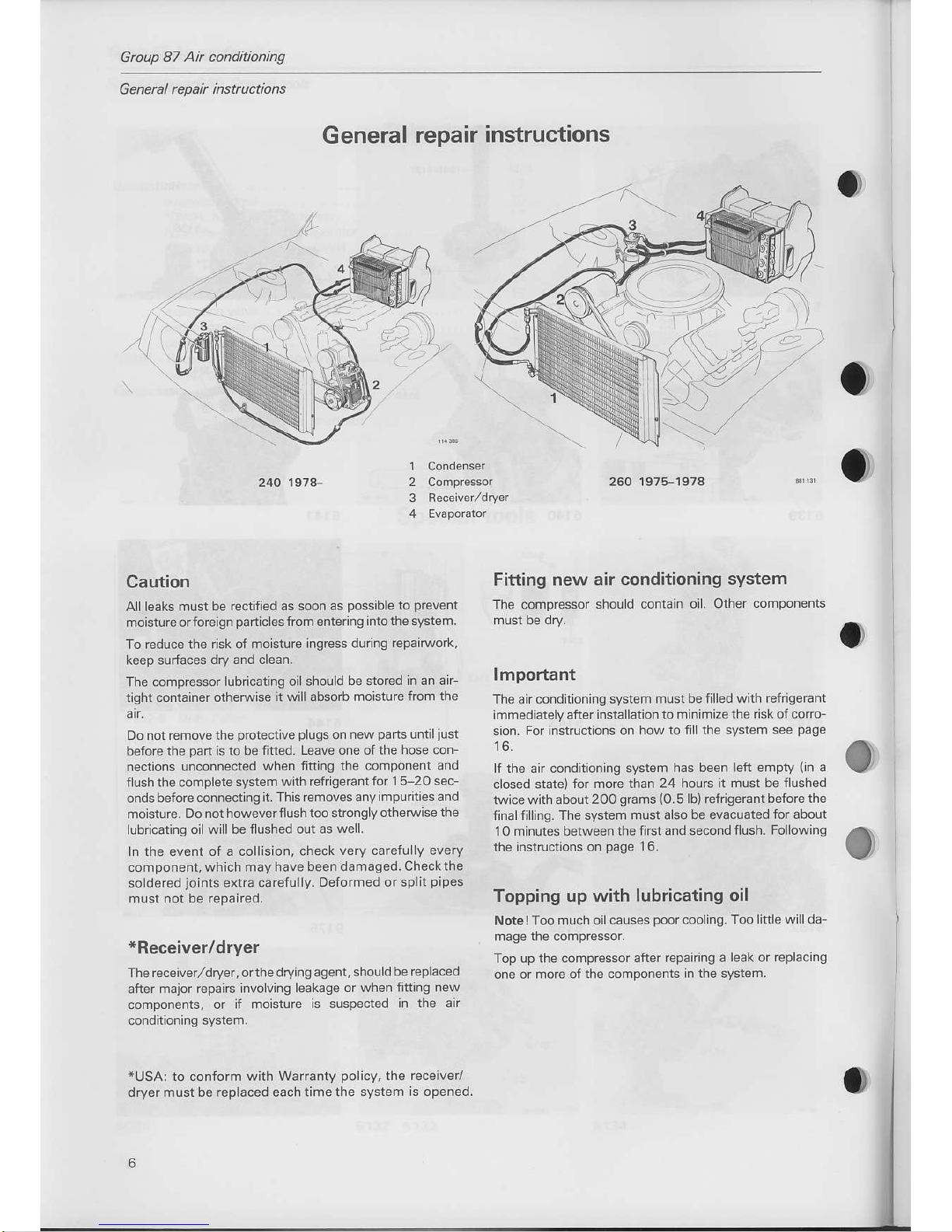
G eneral r epa i insttuctions
General
repair
instructions
..-';.
Caution
A I leaks must
be rectified as soon as
possible
to
prevent
moisture or foreign
particles
lrom entering into
the system.
To r€duce
the risk of moisture
ingress during reparNork,
keep surfaces
dry and cLean.
Ine co-pressor
.ub1car.r9 oir shoulo
be
slo'Fd
In a1 air
tight container otherwise
it will absorb moisture
from
the
air.
Do not rernove the
protedive plugs
on new
pa.ts
untiliust
before
rhe
part
is to be fitled.
Leave one ofthe hose con_
nections unconnected
when fltting
the component and
fllshthe complete system
with refrige.antfor
15-20 sec
ondsbefore
connecting
it. This removes any
impuit€s and
mo sture.
Do not however flush too
strongly otherwlse ihe
lubncating oil will be flushed
out as well.
In the event of a collision, check
very carefu ly every
component, which
may have been damaged.
check the
so dered
joints
extra carefully.
Deformed or splil
pipes
nr!st
not be repaired.
*Receiver/dryer
The receiver/dryer, orthedryingagent,
shouLd
be rcplaced
dfter
-d.orep.tr.,nvolvirg
ledtao" or wl'er'inirq
1ew
components, or
if moisture is suspected
in
ihe air
condltioning
system.
*USA:
to conform
with Warranty
policy,
the
receiver/
dryermust be replacedeach timethe
system is opened.
260 1975-1978
Fitting
new air conditioning
system
The compressor should
contaln oil. Other
components
lmportant
The air conditionlng
system mlst be filled
with refiigerant
immedlatelyafter installation
ro m inimiz€ the risk oi coro-
sion.
For instruclions on how to
fil the system see
page
16.
f the air conditioning system
has been left empty
(in
a
closed state)
for more than
24 houls h mLrst be fllshed
tw ce with about
2OO
gmms
(O.5
lb)
refrigerant before the
finalfill ng. The system
must also be evacuated
for about
10 minutes
between the firstand second
flush. Following
the instructions on
page
16.
Topping up
with lubricating oil
Note I Too
mLrch oil causes
poor
cool
ng. Too ittle will da
mage the compressor.
Top up
the compressor after repanng
a leak or replacLng
one or more of
the components in the system.
240 1974-
I
2
3
o

Group
87 Air
conditioning
Slow leakages
(more
than 24 hours)
Normally this does
not involve any loss of lubicating
oil.
When replacing
components obserue:
Compressor
Drain and measure the oil from the old compressor.
Also drain
the oiifrom
the new
compressor.
Then add
the same amount of oil
(new),
as was drained from the
old compressor to the new compressor.
{At
least 1
dl=0.2
US
pint)
Other components
Drain and measure the amount of oil. Add the
rcquired
amount of oiito the new component
beforc fltting it.
Leakage
safety
precautions
Ouick leakages
(e.9.
burst hose)
This usually involves
a loss of lubricating oil.
The following
volumes apply when fitting a new
compo
dl
US
pint
Drier
o.7
o.5
0.5
o.5
o.3
o.t5
o.1
o.1
o.1
This does not
apply to air condirioning
systems
with
Yo'l compressors.
In such
cases allortrs
added dF
rectry
to th€ compressor.
Always wear
tight tining safety
glasses
when there is danger
of re-
frigerant loss.
Safety
precautions
Use tap water to remove
refrigerant
WARNING!
Gases lormed
by heating refrigerant
are a serious health risk
and can
cause serious lung
damage.
Get in touch with
a doctor ifthe injury does not heal,
or
sight is
affected. Avoid working near
naked flames,
ciga
rettes
etc. Hig h tem
peratu
res
cause th e refrige ra nte
to lorm
poisonous
fumes which are toxic in high
con-
NotelThe gases
ca.| cause
serious lung darage eve.1 in
low
concenrrarrons The
symptoms may rol become
evl
dentfor
several hourc or
perhaps
even a day later.
Safetyglasses should
always bewom when
wo*ing with
or near refrigerants.
Rubber
gloves
should be worn and
allform
of skin contactshould beavoidedsince
refriger
ants
cause trostbite. lf refrige.ant
should contact the
eyes
or skin, splash the eves
or affected area with
cold water
{preferablyfor
15
min)and treatthe injury
in thesame way
WARNING
-
EXPLOSION RISK!
Do not sublect refrigerant
coniainers to high
-,;"
Group 87
Ai
conditioning
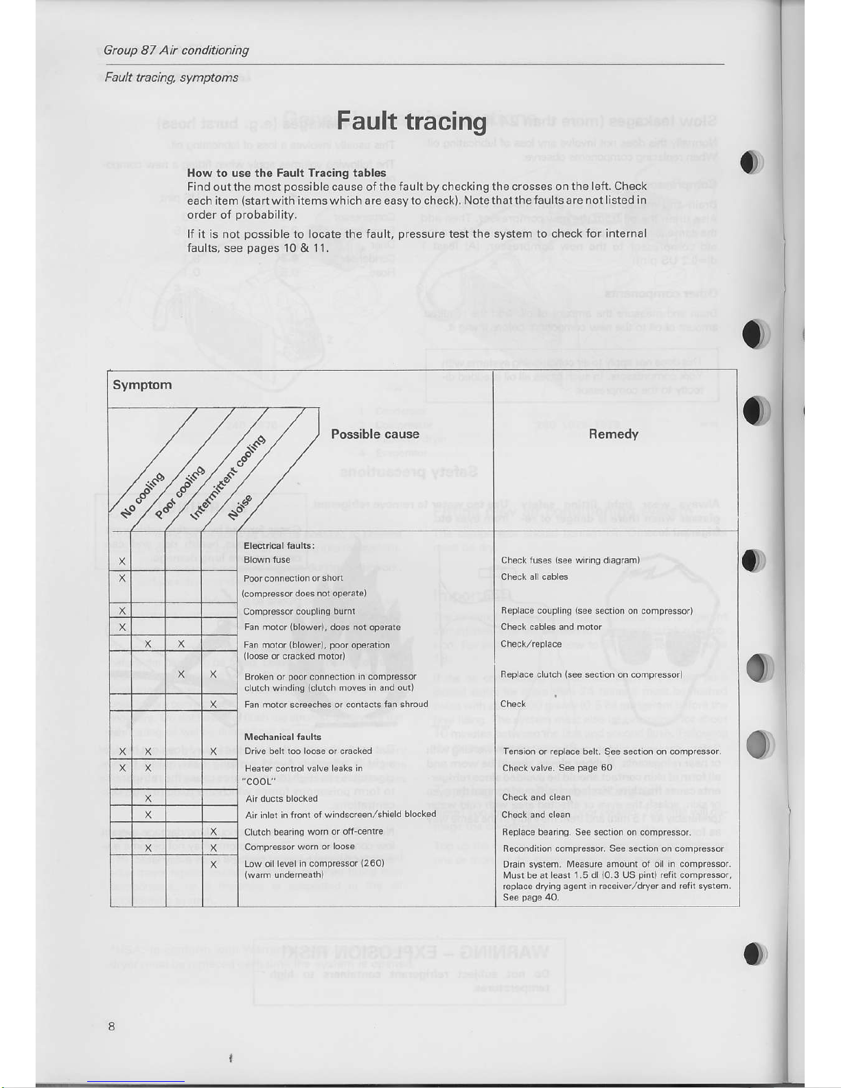
Fault tacing, symptoms
Fault
tracing
How to use the Fault Tracing tables
Find outthe most
possible
cause ofthe fault by checking
the crosses on the left. Check
each
item
{startwith
itemswhich are easyto check). Notethatthefaults are
not listed in
order of orobabiliw.
lf it is not
possible
to locate the fault,
pressure
test
the
system
to check for internal
faults,
see
pages
10 & 11,
o
o
I
BrMnlus€
|
checkflses
lsee
wiin! didsram)
P@r(onnsctiororshor
I
ch€cf alccoles
l@mpr€ssor
do€s nol opsBts)
coFpressor(oupl'ns
bumt
I
R€ol6ca.oJphns rs"P
secr'o1on Lorpr€ssoa
Fan moror
{blowarr.
do.s not op.rdr.
I
Checr caoles ano ndor
Fan molor
{blowor),
poo.
opoEtion
Chock/Gpac€
Brck n or Doorconnection in como4$or
R.pl.c. cluich
(see
seci on oi conpressor)
clutch windinq
(clutch
mwes
in a^dour)
F6n motor scBgch€s orcontacG
fan
shroud I
Ch€ck
I
D.ve belr roo
l@5e
or cra,red
I
Ta.s'on o'
'€pl.ce
b€r
Sse<scnon
on.ompGsror
rla5ra' contol valva od's
n
I
CFscL
valv€. see
pasp
60
an ducb
blocl€d
ch.ck 6nd clean
An inl6i in lrcnt of
windsc Eenlshleld
bock.d
I Cheok and
cl6an
Clutch
baa ng wom
or ofi-cente
R6pac€ b€a ng. S€€ s6ction on comprcssor.
corp,es{,
wo- o,
r@s.
I
F*-"h.-
--pF*-, see secnon on conp,essor
tnw o'llav.l n
(onprcssor
{2501
|
orair sysron.
Medsu.e
dmoun
(warm
lnd.healh)
|
Must be d Lea$ 1 5
dl
10.3
US
pift)
rarh compEssor,
repLace dryins asenr
in €c€iv€/dry.r and retk system.

Group
87 Air
conditioning
Fault tacing,
symptoms
Symptom
--777)possib,ecause
,/^.'/p94Y ,/
/*"lc/,&/"*7
Remedy
EvaForarorrhemosiardoes
notdisensase
compressor
Expansion
!a!e
sruck in opan
position
BLocked
ho.6 or component
A r flow rh@ush
condens6r bocked
Evaporator
blockad on an
coo
ing
sid€
E6pofalo.
lhomosrar
ncorectly adjosidd
nsufiicient
retigerant
iwhistli^g
noise from
evaporaror
near erpans
on valve, bubbles in sichi
slass)
tupansion valv€
capilary
lube
Moisrure in
syslem. C@lng c.pacnysdod
atstan
llew
mnures)rhen
poor.
O.
pooroparction
ar hish ambienr
DEin
r*em,
rep4s4ecdwt
See
paae
15,
t6
5a.
check/rcplac.
thdrmostat
See
pag6
54
Top-op sysrem.
Find eakase
and repan.
Check Jlow ihroush
each componeni.
Add GfriseEni
S.a
pase
16
Check
lhemostat.
See
pag6
54.
Drain
and rafil
system. See
pag4
15 16
Drain.ysrem,
replaco
receiverldryer
ordyins
agent, fil
wih
retrlgeranr.
See
paq€
15.
orarn
system, rep
ace raceiverldryer
or dyins
asem, litl
w th rerr
se6nt.
See
pag6
15.
Replace
!a ves on r..everldryer
SeepageS6
Check evapo€tor
rhormosrar.
See
pago
54. Tesr
wnh
Ch6ck/r6plrce
See
pa96
54
Dmii
Sysiem
Reft a.cod
nO id
pages
j S j
6.
Su.lion
discharQe valveseiz6d.
Low
pressuB
n fronr ot
compressor,
low suction
{MoisruG
in
syslemJ
ce on
evaporaioratr c@lnq
sde
{ihomosiar
adjusted
tm ow or ran
nor op6rar ns)
Loose evaporator rhermosrar
P@rcontactbetweonorpansionvalvecap
I
aryiob66nd
evaporaror
ou llel or
poor
insularon
T@ l6r€e a d fierence
belween ofiand on lor evaporator
Syfem
d.rtull causes
cr.shins
noiso or vib€tions
rrom h
sh
prcssurc
lines,
ctckins nose
trom compres
sori exdessive
compressor
pr€ssuG
and sucion
pGs
suro, hiss ns
nois€ fbh
expansion va ve,
bubbtas orva
pour
in sisht gla3s.
ll conpr€ssor
vatves
damased
by
derfillins,
compr.ssor
pressur.
witbe
loo low
Moislure
in sysiem,
c.n cause noso
from expanson
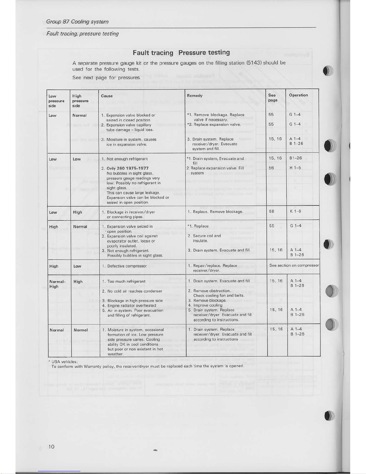
Group 87 Cooling systern
Farlt tacing.
Ue66ure
Esting
Fault tracing Pressure
testing
A s€parate
pressure gauge
kit
or
the
pressure gauges
on lhe lilling station
(5143)should
be
ussd for ths following tests.
S€e n€xt
pag€
for
pr€ssur€s.
To
contom
with W.rsnly
policv,lh.
E@ivor/dryer musl
bo r.pltc.d 6ach liho the syslem
k op€ned.
HiSh
1 - Exp€mion valv. bl@k€d or
6.iz€d in clos.d
pcsition
2. ExpEBion €lv6 oplllary
tub€ damaqe - liqoid
lc.
3. Moistu6 In 6vsi6m, ca!$t
ico in dp8cio valv..
11.
R€move blocl€96. R€pla@
12,
R.pl6c6 sFNion v.lv.,
3,
DEin
st€t.m.
A.pllc€
r€coiv.r/dry.r.
Evaclaro
55
15,16
B 1-26
1 . Not mugh
r€frig.Enl
2. O y 260 19t6-1977
No bubbl6 in sisht
sl.sr,
p@surs
galgo
rordhlF v€ry
lM. Posslblv no rdtdeamnr
in
This can cao.o
larg. l6.k€g3.
Erpansion utu€
crn b. bl@ksd or
seiz€d
in
op.n
pcilion-
rl,DEin3yd€m,Ev€cu.t
.nd
ntl
2, Feplace expansion valve, Fill
16.16
56
B1-26
H 1-5
Hish
1 - Bl@k6€€ in iocetver/dryer
1
Roplace R€md6 block6g€. 58
Hlgh
1 , EtpaNion
valv. s€iz.d in
2. Apamion v€ts 6il 6!6insr
4.poBrd
dtrEr, r@s€ 4
3- Not .f,ouqh Efrig66nt,
Pcsilly bubbl*
in
3isht
sl.Bt.
3. Odin svsl€m,
Ev.cu.t .nd filt. 15,15
G14
B 1-?6
1. R.pailGplac.. B.pla@
S€€ 3€ction on compressor
Hlgh
High
2. No @ld .ir
r.rch.. @nd€B.r
3. Bl@k8g. in high
pBsuro
sid€
4. Engin. €diator dsft.ar.d
5. An in sysr€n, P@r €vaclatio
End filling ol .sfigorant,
L
DEin
st$6m.
Ewaaro andfll
ch6ck cFling lan and
b.lG-
6. DEin s'€tom.
R.pl6c.
@co'vdldry€r.
Ev&uat and fill
accodino
to imtrucrionr.
B 1-26
B 1-26
1 . Moisture in sist€m, @c..iorl
lom.rion ot i@.
Low
presuE
sido
9@6!F
v.ri6. c@ling
ability OK
in c6l @nditioB
blt
pod
or mn disronr h hot
1,
Dr.in
sy.t.m.
R.pl!c.
@.iv.r/dry.r.
Ev.cuar6 and fll
.c6ding ro isrrudions
15,16
B 1-26
10
Group
87
Air
conditioning
Fauk
tracing,
prcssure
testing
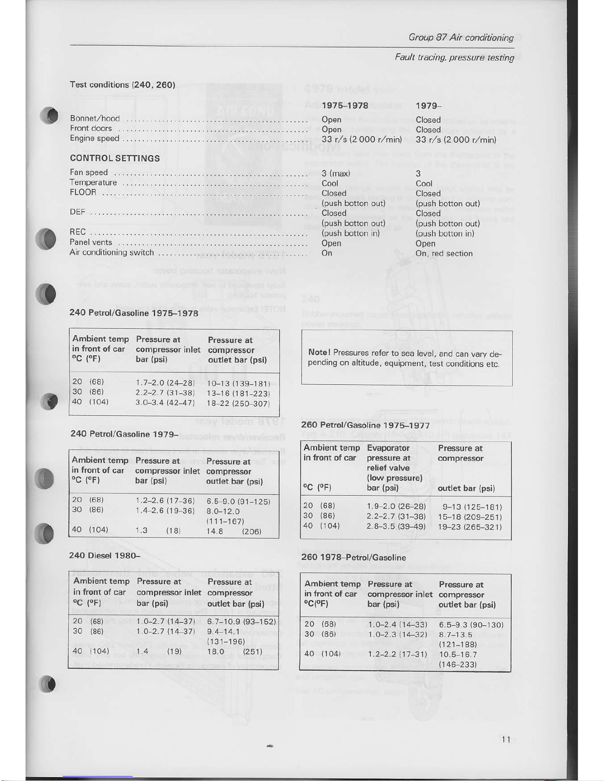
Test
conditions
{24O,
260l
1975-1978
1979-
Closed
Closed
(2
0OO r,/rnin) 33 r,/s
{2
OOO r,hin)
CONTBOL
SETTINGS
Engine
speed
Open
Open
33 t/s
3
(max)
Cool
Closed
Closed
Open
On
3
Cool
Closed
Open
FLOOR
DEF
aEc
An
conditioning swrrch
240 Petrol/casoline
1975-1
978
24O Petrol/casoline
1979-
2/tO Diesel 198G-
Notel
Pressures
refer to
sea level,
and can vary
ae
pending
on altitude,
equipment, test
conditions
erc.
260 Petrol/Gasoline
1 975-1
97?
260
1 978-Petrol/Gasoline
Ambient
temp Evaporator Pressure
at
in ftont oI car
pressure
at c.mpressor
feliefvalve
(low
pressurel
'c
{'F)
bar
(psi}
outlet bar
{psi)
20
(68)
19-2.0\26-28)
913(125
181)
30
(86)
2.2-2.1
B1
3Al 15-18
(209
251)
40
(104)
2
8-3.5
(39-49)
19 231265_3211
Ambienttemp
Pressure
at Pressure
ar
in front
of car compressor
inlet compressor
'ceF)
bar
(psil
outlet bar
{psi)
20
30
(68)
1.0 2.4
(14-33)
6.5 9.3190-130)
(86)
1.O-2.3
114,32t
A 1-13.5
(r
21_188)
(104)
1.2 2.2111-31) 10.5
16.7
(146_2331
Ambienttemp
P.essure
ai
pressure
ar
in lront
of car compressor
inlet
compresso,
oC
{oF)
bar
(psil
outlet bar
(psi}
20
168)
1.7
2.a\24
2A1
10 13(139
181)
30
(86)
2.2-2.7
l314at
13_16
(1S1_223)
40
(104)
3 V3 414247)
1A 22
Q\O
3a7)
Ambiem
temp Pressure
ar
Pressure
at
in front
of car
compressor
inler comDressor
'c
fF)
bar
tpsil
ourtet bar
(psil
20
(68)
1.2 2 6
117
36)
6.5 9.0
(91
125)
30
{86) 1.4-2.6
9-36)
8.O_12.0
(111_167)
40
(to4)
1.3
(18)
14.8
(206)
Ambient
temp Pressure
at Pressure
at
in front
of car compressor
inlet compressor
'C
{.F)
bar
(psi}
ourlet bar
(psi}
1.4-2.7
\14-37t
6.7 1O.9
(93-r52)
1.O
2.7
114-371
9.4-14.1
(131-196)
1 4
(19)
18 0
(2s1)
1t
Group 87 Ah conditioning
Modilications
Modifications
'l
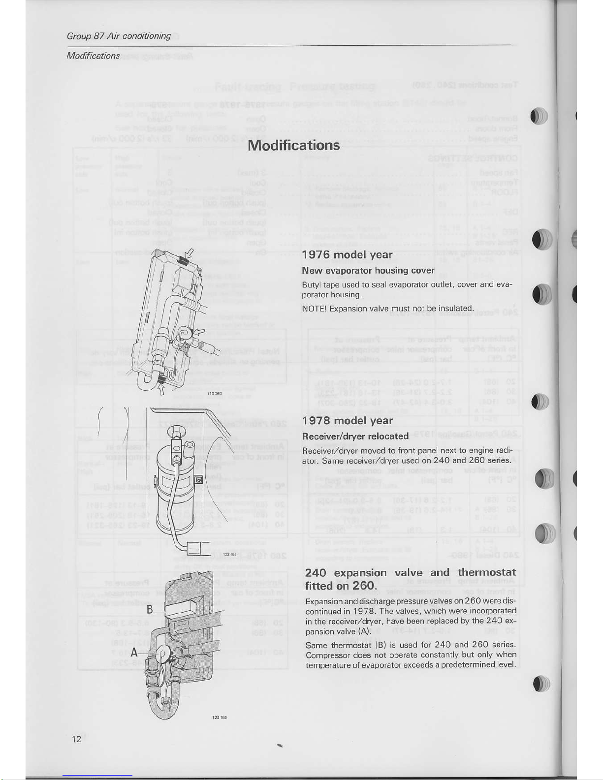
1976
model
year
New evapoEtor
housing covel
Butyl taps used to seal evaporator
outl€t, cover and eva-
NOTEI Expansion valve must
not be insulated.
1978
model
year
Receive/dryer
relocated
Receiv€r/dry€r moved to lront
panel
next to engine radi-
6tor. Same receiver/dryer
us€d on
240
and
260 seies.
240 expansion
valve and
thermostat
fitted on 260.
Expansion and discharge
pressurs
valves on
2 60 wers dis-
continued in
1978. The valves,
which w€rs incoporated
in the r€ceiver/dryer,
have bsen replaced
by the 24o ex-
Same
themostat
{B)
is used
for 24O and 260 series.
Compressor
does not opsrate constantly
but only when
temperaturs of evaporator exce€ds
a
predetermined
level.
't2
Gtoup
87 Ah
conditioning
Modificatlons
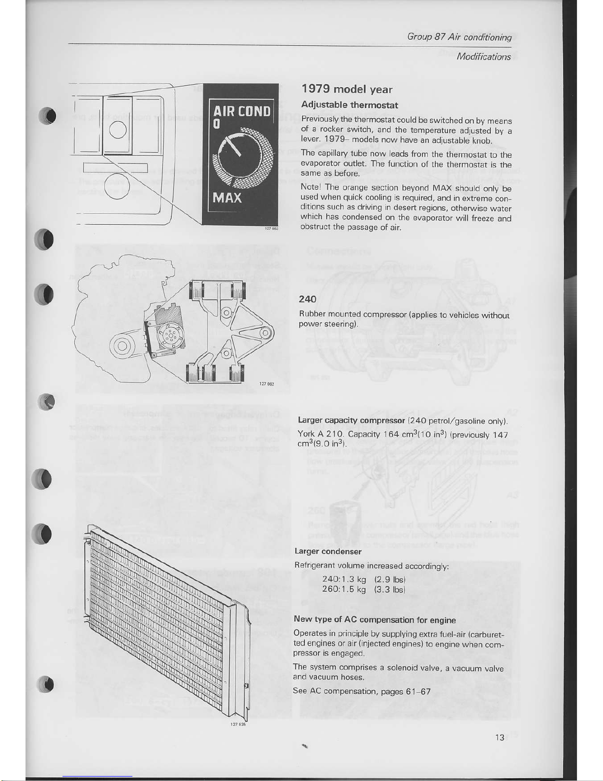
1979
model
year
Adjustable
thermostat
Prevlouslythe
thermostat
could be
switchedon
by means
oi a rocker
switch,
and the temperature
adjusteo oy
a
lever. 1979-
modes
now have
an adjustable
knoo.
The
capillary
tube now leads
from
the themostat
io the
evaporator
outer.
The function
of the
thermostat
is rhe
Notel The
orange
secton beyond
MAX
shoutd onry
oe
used
when
quick
cooling is required,
.nd
in exrretrre
oon-
ditions
such as
driving in desen
regions,
otheNise
warer
which
has
condensed
on the evaporator
w I
freeze and
obstruct
rhe
passage
of air.
240
Rubber mounted
compressor
{appties
to vehictes
wmour
Larger
capacity compressor
1240
petrol,/gasolre
on,y,.
York
A 210. Capacity
164 cm3(1O in3)
(previousty
i 47
cmJ(9.O inr).
Refrigerant
volume
increased
accordingty:
24O:1.3
ks
(2.9
lbs)
260:1.5
kg
(3.3
tbs)
Newtype
ot AC compensation
for engine
Operates n principle
by supplying
exrra fuelair
(caburet-
ted
engines
or air(injected
engines)to
engine
when com-
The
system comprises
a solenoid
valve,
a vacuum
valve
See AC
compensarion,
pages
61-67
p
t3
Gnup 87 Ai conditioning
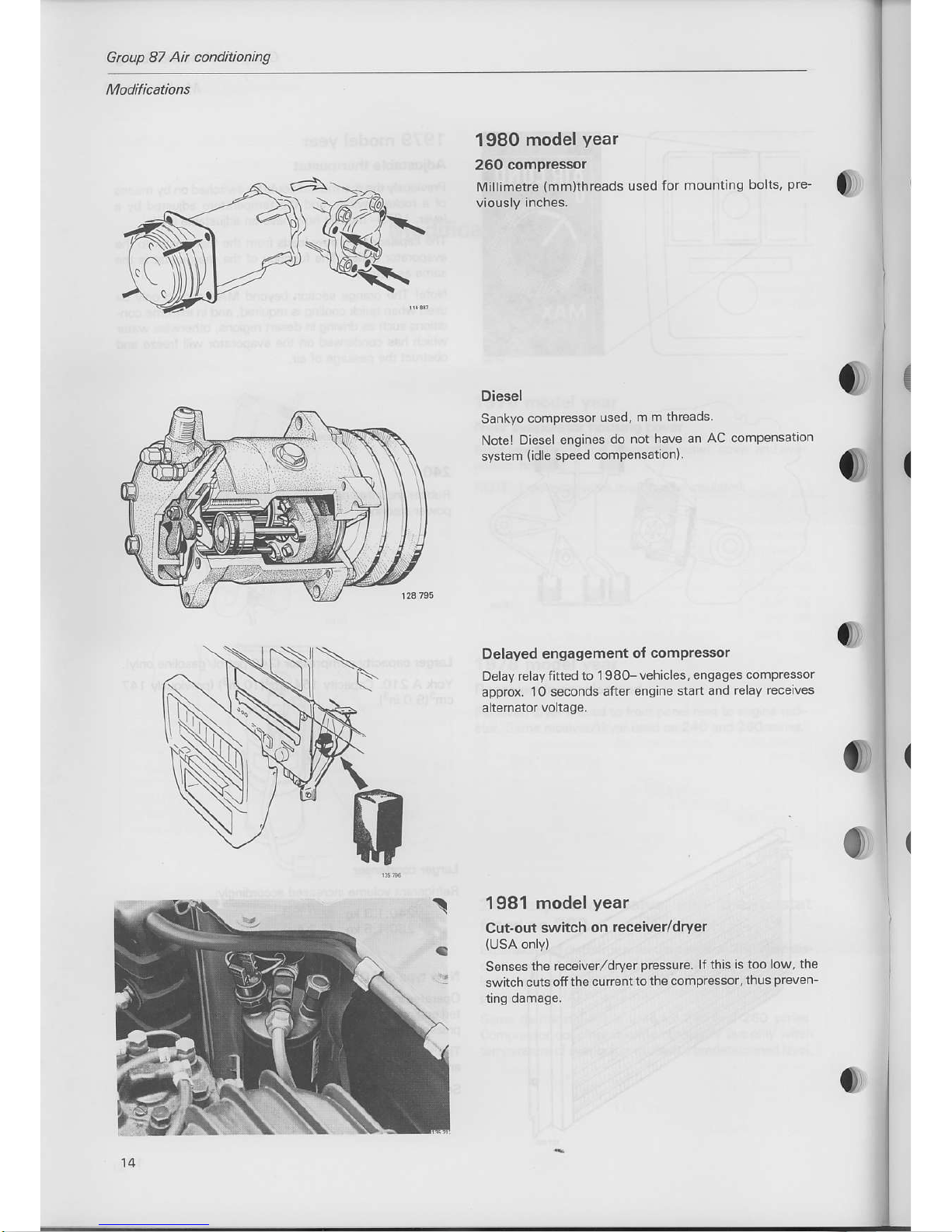
1980 model
year
260
compressor
[4illimetfe
(mm)threads
used
for
mounting
bolts,
pre'
0)
0
Delayed engagement
of
compressor
Delay relay iitted
to 1 I8G- vehicles.
engages compressor
approx.
10
seconds
after engine srdr
ard relay
receiv's
Diesel
Sankyo
compressor
used,
m m threads
Notel
Diesel engines
do not
have an
AC compensation
system
(idle
speed
compensation)
1981 model
year
Cut-out switch
on receiver/dryer
(USA
only)
Senses
the rcceiver,/dryer
prcssure.
lfthis
is too low,
the
switch cuts
offthe curenttothe
compressot,
thus
preven_
rmg oamage.

Gtoup
87
At
conditioning
Drcining rcfigennt
A. Draining refrigerant
Special tool: 5143
Read the safety
precautions
on
page
7.
The AC
system
must be drained if the refrigerant circuit is disconnected or ifone or more of the components is replaced.
The
pressure gauge
set on
filling station
15143)should
be used; make surethat the
pressure
gauges
are closed before con-
Connections
Nipples
should be fingerright
only.
Disconnect
the battery
negative lead.
240 Pet.ol/gasoline
and diesel
Remove the
cover nuts
and connect the
btue hose to the
compressor
"suction"
side and the
red hose to the
outtet
side marked
"disch
.
A2
2601975-1977
Remove the cover
nuts and connect
rhe red hose
(high
pressure)tothe
compressor
(small
pipe)
and
the btue hose
llow
pressure)
ro
the equallsrng valve
on the suspensron
A3
260 1978-
Remove the cover
nuts and connect the red hose
(high
pressure)to
the compressor
(small
pipe)
a nd the
blue hose
{low
pressure)
to the compressor
(large
pipe).
Gtoup 87 Ah conditioning
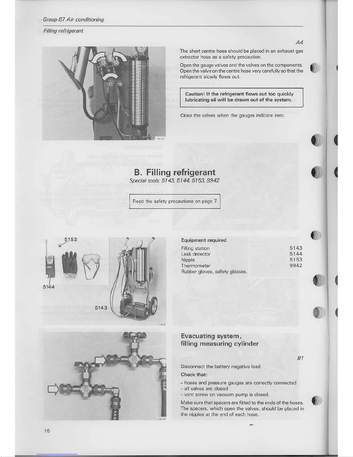
A4
The short centre hose should be
placed
in an exhaust
gas
extraclor hose as a safety
precaunon.
Open the
gauge
va lves
and
lhe valves on the components.
Openthevalve onthe centre hose very carefullysothatthe
refrigerant slowlY flows o!t.
Caution I
lf the relrigerant flows
out
too
quick
ly
lubricating oilwill be drawn out of the system
Close the
valves when the
gauges
Ind cate zero.
0
0
(
(
B. Filling refrigerant
Special tools:
5143, 5144, 5153, 9942
Bead the safety
precauiions
on
page
7.
0
0)
5143
5144
5153
9942
0
I
Ii
Equipment required
Filling station
Nipple
Rubber
sloves,
safery
slasses.
5143
0
Evacuating
system,
filling measuring cylinder
Bl
Disconnect the battery negative lead.
Check that:
-
hoses and
pressure
gauges
arc coftecny
connected
allvalves arc closed
-
venr screw on vacuum
pump
]s ooseo.
Make sure that
spacers are
fitted
to the ends ofthe hoses.
The
spacers, which open lhe valves, should be
placed
in
the nipples at the end of each hose.

Gtoup
87 Ai conditioning
B2
connect
hoses to
component
See
page
15.
Connect centre shon hose to vacuum DumD
Cautionl Do not
open the valve until the
cylinder is
B4
Make sure that measuring cylinder is empty
This can be checked at the liquid indicator in the centre of
the cylinder. lf empty. it must be evacuated
at
the
same
Method:
Open
the
outlet
valve
on the measu ng cylinder, see fig.
B3
o
B5
Fully
open
gauge
valves and valves at compo-
nents
B6
Sun vacuum
pump
B7
Open the vacuum
pumpvalve
slowly
(the
cente valve be-
low the
pressure
gaugesl.
1l

Gtoup 87
Ah conditioning
B8
Turn vent
screw on vacuum
pump
one
turn
clock-
Leavethe
pumpon
1,/2-1 minule andthen
closethe vent
This
sperformed to renrove moisturefrom
the system and
from the oil in the
pump.
A hlgher depression can
be ob
B9
Evacuate system until low
pressure gauge (on
left) indicates nearly - l bar
(-14 psi),
then run
vacuum
pump
for a further 30 minutes,
Note! lf the temperature is below 3OoC
{86oFl
the vac
uum
pump
should
be left running for a further 20 minuies,
all together 50 minules.
Close thevacuum
pumpvalveand
alsothe outletvalve on
the measuring cylinder
(if
evacuated).
Switch off the vacuum
pump.
lf the specified depression cannot be obtained or if it drops
on
closing the valves, there is a leak in the systern.
Find and coffect the
leak
and evacuat€ the system once
{,
E.s. 1 5OO metres
(4
920 ft) above sea evel
=5xO.034+O.17
bar
(2.37
osi)
reduced
pres
su'e + aop'o\. - 0.82 b"
6
Bto
ei
0
Btl
The following
procedures
only
apply iI the
measudng cylinder has been evacuated or ifthere
is less than 1 600, 1 800 or 2 000
grammesrre-
frigerant in it
(depends
on
year
and
vehicle type).
In other cases
proceed
to leak testing, 816
The above values are vaLid ai
(orclose
to)sea level.
Pressurcs
should be reduced by 0.034 bar
(O.47
psl)for
every 3OO metres 984 ft above sea leve
600
s
=
3.6
lbs, 18OOs=4lbs,2OOOg=4.5
(
(
(
I
Group
87
Air
conditioning
I
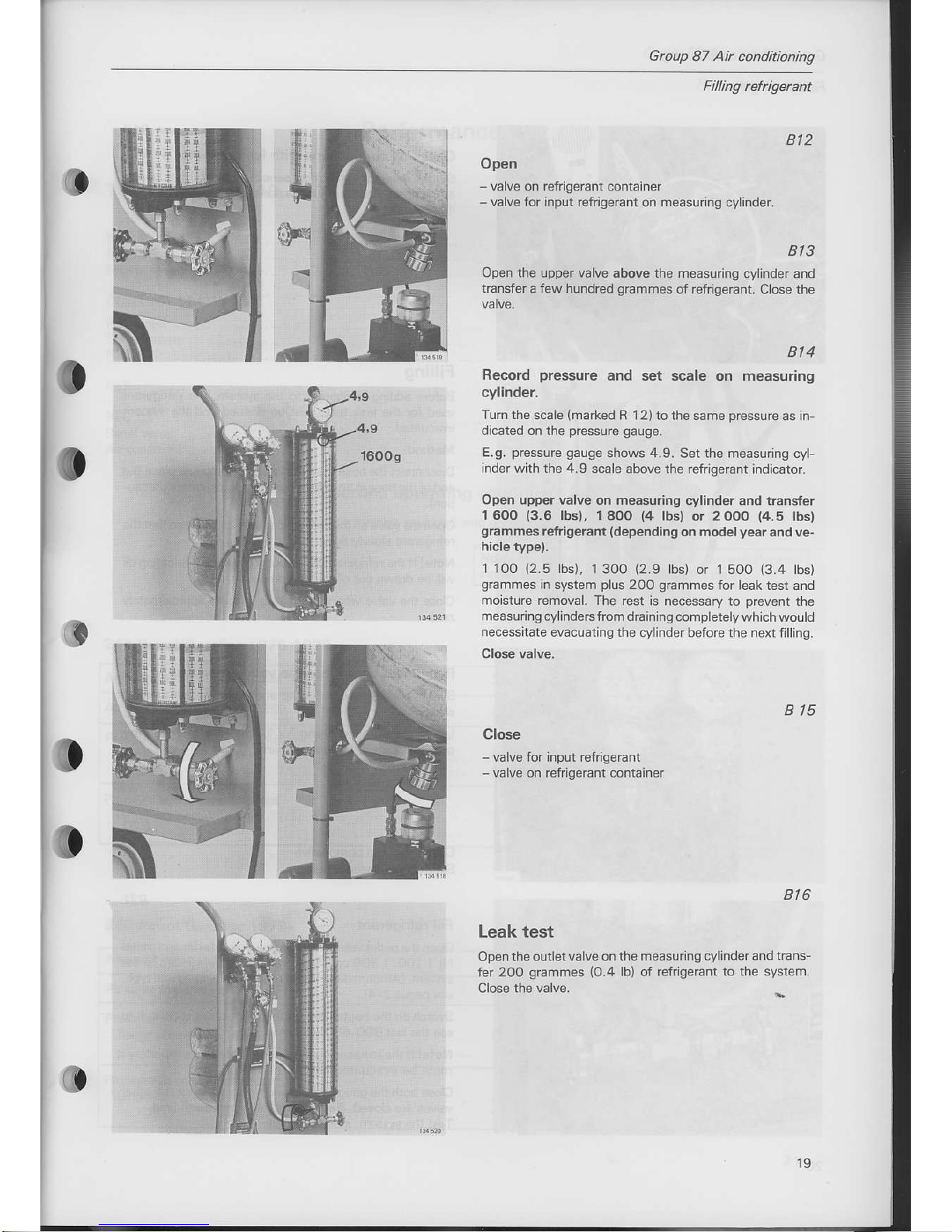
Bt2
Open
-
valve on refrigerant container
-
valve for input refrigerant
on
measuring
cylinder
Bt3
Open the upper valve above the
measurlng cy inder and
transfera f€w hundred
grammes
of refrigerant.
Cose the
3
Turn ihe scaLe
{marked
R 12)to the same
pressure
as
ln
dicated
on the
pressure
9auge.
E.g.
pressure
gauge
shows 4.9
Set the measLring cyl-
inder with the 4.9
scale above the refrigeranl indicaror.
Open upper valve
on
measuring
cylinder and rransfer
1600
{3.6
lbsl, 18OO
(4
lbsl or 2ooo
{4.5
lbsl
srammes
refriseranr
(dependins
on modelyear and ve-
hicle
type).
1 1O0
{2.5
lbs), I3OO
(2.9
bs) or 15oo
(3
4
lbs)
g€mmes
n system p !s 200
grammes
for
eak test and
moisture remov3l. The
rest is necessary to
prevent
the
meas!.ing
cy indersfrom dra ning comp
erelywh ch would
necess
tate evac!aring the
cylnder before the next filllng
Close valve.
Bt
4
Record
pressure
and set scale on measuring
cylinder.
B t5
Close
-
va ve for input refilgerant
va ve
on
reirigerant
contain€r
Bt6
Leak test
Open the ouiletvalve on
the measuring cyl nder and
trans_
fer 2oo
grammes
(O.4
lb)
of
refrigerant to the system
:c
t9

Gtoup 87 Air conditioning
Fi ing refrigercnt
Bt7
Check all connections
with leak detector
5144
Set the detector
to the most sensitive
field
(buzzes
nearlv
all the time). R ectit
any leaks and
perfom
a new leak test
Bt8
Filling
Before adding rcf
gerant
to the system, the refrigerant
used for the lsak test must be
drained and the system
Method:
Disconnectthe hose frcm
the vatuum
pumpand place
the
end of
the hose in an exhaustgas extractor
{safety
precau-
Openthevalveonthe
centre hose verycarefullysothatthe
refrigeEnt slowly flows out.
Note! lf the refrigerant flows outtoo
quickly
lubricating oil
will be drawn out of the compressor.
Close the valve when the
gauges
indicate approxamately
Bt9
Reconnect cente hose to
vacuum
pump.
Switch on the vacuum
pump
and open
the
pump
valve
Leave the
pump
running for 10 minutes after
the low
pressure gauge
indicates nearly
-1
bar ( 14
psi).
820
Close vacuum
pump
valve
Switch off vacuum
pump
821
Fill refrigerant
Openthe outlel
valve
on
the measuring cylinder and tlans-
fer 1 1OO, 1 30O or 1 50O
grammes
of refrigerant
to the
system.
{Amount
depends on model
year
and vehicle
rype,
see
pages
2-4).
Switch on the heater unit forthe cylinder
if it is difficult to
see
the last
30MOO
grammes.
Note! lfthe measuring cylinder is drained completely
it
must be
evacuated
before the next filling,
Close both thegauge valves and
makesurethatthe other
valves are closed. Reconnect the battery earth
lead.
Test the system,
see next
page.
Group
87 Air conditioning
C
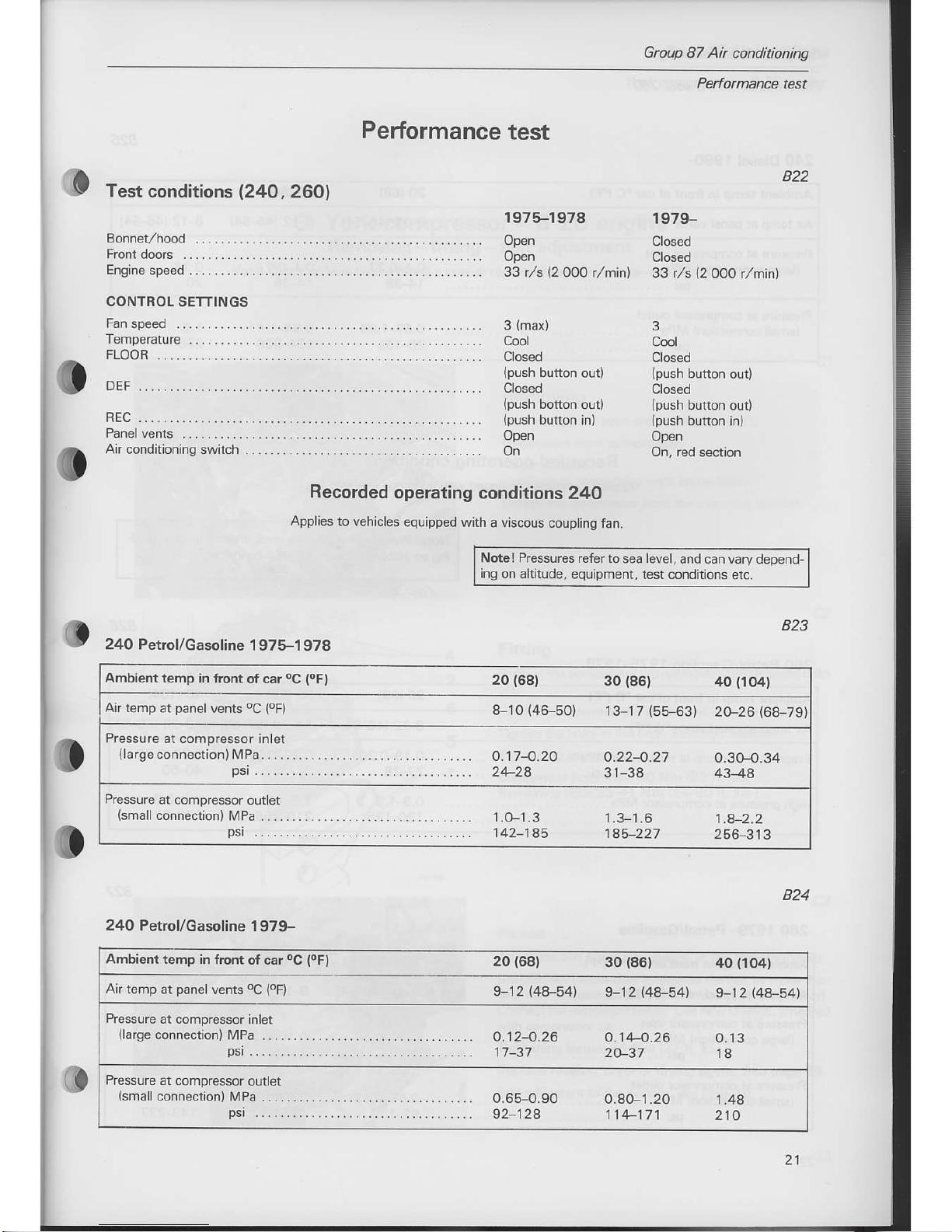
Test
condition
s
l24O,260l
Performance
test
822
823
824
197+1978
Open
Open
s3 t/s
\2
00O
l-rlinl
3
(max)
Cool
Closed
Closed
Open
On
1979-
Closed
Closed
33 t/s
l2ooo
l[]'in)
3
Cool
Closed
Closed
Open
CONTROL SETTINGS
FLOOR
o
DEF
Air conditioning switch
Recorded
operating conditions
24O
Applies to
vehices equipped
with a viscous
coupling
fan.
Note
I Pressures refer io
sea
level,
and can vary depend
ing on altitude,
equipment, test conditions
etc.
240
Petrol/Gasoline
1 975-1 978
24O Petrol/Gasoline
1979-
Ambienttemp
in front
of car
oC
(oF)
20
{68)
Ambient
temp in
front ot car
oC
(oF)
20
1681
30
(86)
40
{104}
Air temp
at
panel
vents
oC
(oF)
9
12
{48-54) 9-12
(48-54)
9-12l4e-541
Prcssure
at compressor inlet
(large
connedion)
MPa ....
psi
......
o.t24.26
11-31
o.t44.26
20-37
o.13
18
Pressure
at compressor
outlet
(small
connection) MPa
.....
psr
......
o.65-O.90
92 128
o.80-1.20
1 14 111
1 .48
210
21

Group
87 Air conditioning
Momance test,
Diesel, 260
240
Diesel 198G
Ambisnt
temp in tront of car
oC
{oF)
20
1681
30
(86)
/tO
(lO4)
Air temp at
panel
vents
oc
{oF)
8-12 {46-54)
U12@6-541
8-t2|.46-541
Pressure at compressor
inlet
{large
connection) MPa
....
psi
......
o.14.27
14-38
o.14.27
ft44
0.14
20
Pressure at compressor
outlet
{small
connection} MPa
.....
psi
....-.
o.67-1.09
95-155
o.94-1.41
134-200
1.4
Recorded
operating
conditions
260
Applies to vehicles
equipped with a
viscous coupling
fan
Note
I Pressures refer
to sea level,
and can
vary depend-
ing on aftitude,
€quipment,
test conditions
etc.
826
@
260 Petrol/Gasoline
1975-1
978
Ambient temp
in front of car
oC
(oF) 20168t
30
(86)
40
(1()4)
Airtemp at
panelvents
oC
(oFl
8-r2
(46-54)
14-20
{57-68)
20-28
{68-€2
Evaporator
pressure
at
relief valve
MPa
psi
...
0.1s-o.20
27-24
o.224.27
31-38
o.2g-0.35
40-50
High
pressure
at compressor
MPa
.
psi
...
o.9-1.3
130-185
1.5-1 .I
2 to-256
1.9-2.3
270-320
260 1 979-
Petrol/Gasoline
Ambient
temo in
front of car
oC
(oF) 20
{68)
30
{s6)
iro
(1o4)
Air temp ar
panel
vents
oC
(8oFl
9-12 {48-54)
9-12
@a-541
9-12
(48-54}
P.essure at comprcssor
inlet
{large
connection)
MPa ....
psr
' ....
0.10-o.24
14-34
o.10-o.23
o.124.22
17-32
Pressure at
compressor outlet
(small
connection)
MPa .....
psi
......
o.65-O.93
92-132
0.87-'t.35
124-192
1.0F1.67
149237
Group 87 Air
conditioning
Q
York
compressor
B 20 engine
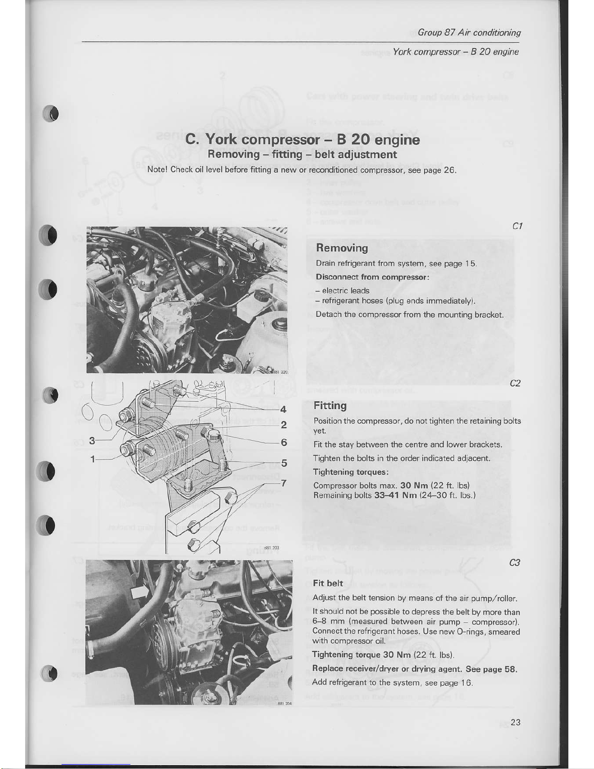
C. York compressor
-
B 2O engine
Removing - fitting
-
belt adiustment
Notel Check oil level before fitting
a new or reconditioned compressor,
see
page
26.
Removing
Drain
refrigemnt from
system, see
page
15.
Disconnect lrom
compressorl
-
refrigerant hoses
{plus
ends immediately).
Detach the
compressor from the mountlng
blacket
c2
Fitting
Posltion the compressor, do nottightenthe retaining bolts
Fit the stay between the centre and lower brackets.
Tighten the bohs in the
order
indicaied adjacent
o
CI
(|
1
Tightening
torques:
Compressor bolts max.
Remainlns bolts 33-41
30 Nm
(22
ft.
lbs)
Nm
(24-30
ft. lbs.)
o
C3
Fit belt
Adjust the beh
tenson by means
ofthe air
pump,/roller.
It sho!ld not
be
posslble
to depress
the belt by more
rhan
6 8 mm
(measured
between air
pump
compressor).
Connectthe refrigerant
hoses. Use newO
rings, smeared
Tishtening
torque
30 Nm
(22
ft. lbs).
Replace receiver/dryer
or drying agent. See
page
58.
Add
refrigerant to the
svstem, see
page
I6.
4
rf
23
 Loading...