

Volvo 240 1975, 260 1975 Service Manual
Service
Manual
Repairs
and maintenance
Section 8
(87)
Climate unit
(Heater
unit)
240,260
1975-
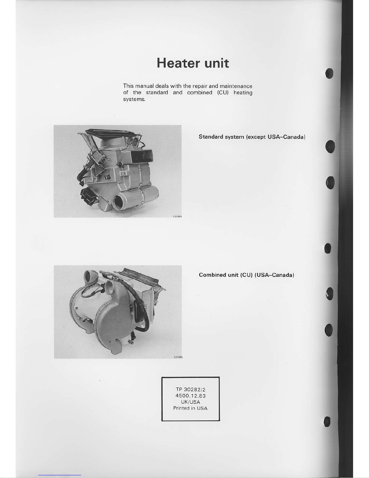
Heater
unit
This manualdeals with
the repair and maintenance
of the standard and combined
(CU)
heating
Standard system
{except
USA-Canadal
Combined unit
(CU) (USA-Canada)
IP 30282t2
4500.1
2.83
UK/USA
Group 87
Climate
Contents
unit
(Heater
unit)
Standard
unit
Control
panel
and,/or cable, replacement
Operation
A1-A10
B 1_82
cl c24
D1-D23
E1_E9
F1-F20
Page
14
Fan motor
switch, replacement
Heat
exchanger and,/or fan motol
Heater control
valve, replacement
Air distribution
1 975-1980
1981-
replacement
(removed
heater)
2
3
4
I
Combined
unit
(CU)
USA-Canada
Heater contrcl
and,/or conrol cable, repla
cemeni
c 1
-G
7
Contrcl
panel
and,/or fan motor
switch, replacement
.. .... . . . .
Shutter actuator for
rcar
floor
vent, replacemenr
REC
shLtte'. replacement
Hedler,.emoval
...
Insrallarron
..
Hedl
erchanger. repldLement
rremov€d
h.ater)
t.n motor
replacemenr
Heatercontro
valve. replacement .......
H1-H7
t1-t6
J]
J2
K] K26
L1 t21
M] Ml6
N1-N36
o 1-06
P1-P13
R1-R17
21
22
23
24
25
30
35
38
45
46
49
Charts
A. Heater controls,
standad lnit
B. Healer
convols, CIJ
C. Standard
heater unit
D. Heater
housing, standard
unit
E. Combined heater
unit, CU
F. Heater
housing,
CU
G. Hole template,
standard
unit
H. Conversion
table
metric,/IJSA
standard
Index
page
53
fhis
manual deals with heater units
only. Air conditioning
is
dealt wlth in another nran!al.
Volvos
are sold
in
versions adapted for different markets.
These adaptions depend on many factors
including legal,
laxation
and
market
requirements,
This
manual may lherefore show illustrations
and text
which do not apply to cars in
you.
country.
Group
87 Standa.d
unit
Control
panel
and/or cable,
replacement
Standard
unit
(except
USA-Canada)
A.
Control
panel
and/or
cable, replacement
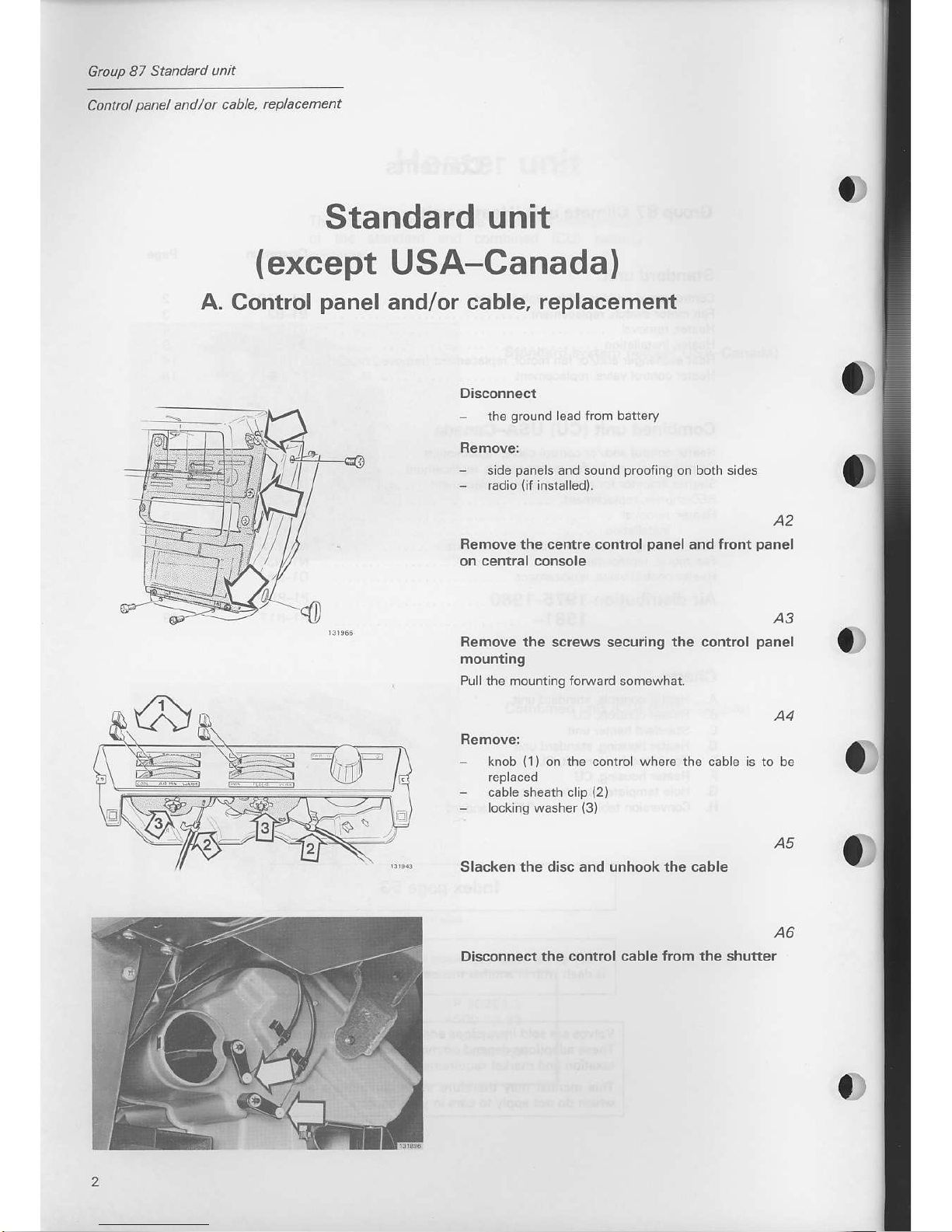
Disconnect
the
ground
lead fiom
battery
Remove:
-
slde
pane
s and sound
proofing
on both sides
-
ladio
{if
installed).
A2
Remove
the cefire control
panel
and tront
panel
on central console
a)
A3
Remove the screws securing the control
panel
moufirng
Pull the mounting forwad somewhat.
knob
(1)on
the control where the
cable
-
cable sheath clip
(2)
-
locking washer
(3)
Slacken the disc and unhook the cable
O)
O)
Disconnect
the control cable from the shutter
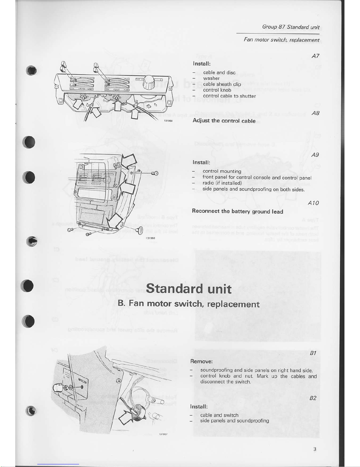
Adjust
the control
cable
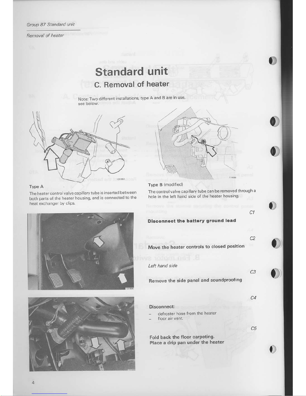
Install:
control
mounting
-
front
panelfor
cenrral
console
and controt
panel
-
radio
(if
installed)
-
side
panels
and
soundproofing
on borh sides.
Group
B7 Standard
unit
Fan
motor switch,
replacement
Ato
A7
Install:
-
cable
sheath clip
-
contro
cable to
shutter
Reconnect
the battery
ground
lead
Standard
unit
B. Fan
motor
switch, replacement
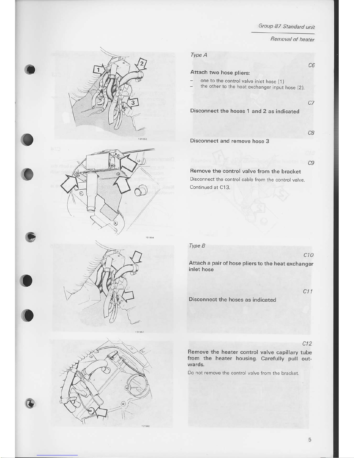
BI
Remove:
-
soundprcofing
and side
panels
on right hand
side.
-
control knob
and nut. Mark
up rhe cabes
and
disconnect
the switch.
Install:
-
cable and switch
-
side
panels
and soundproof ng
o
B2
Gtoup
87
Standad
unit
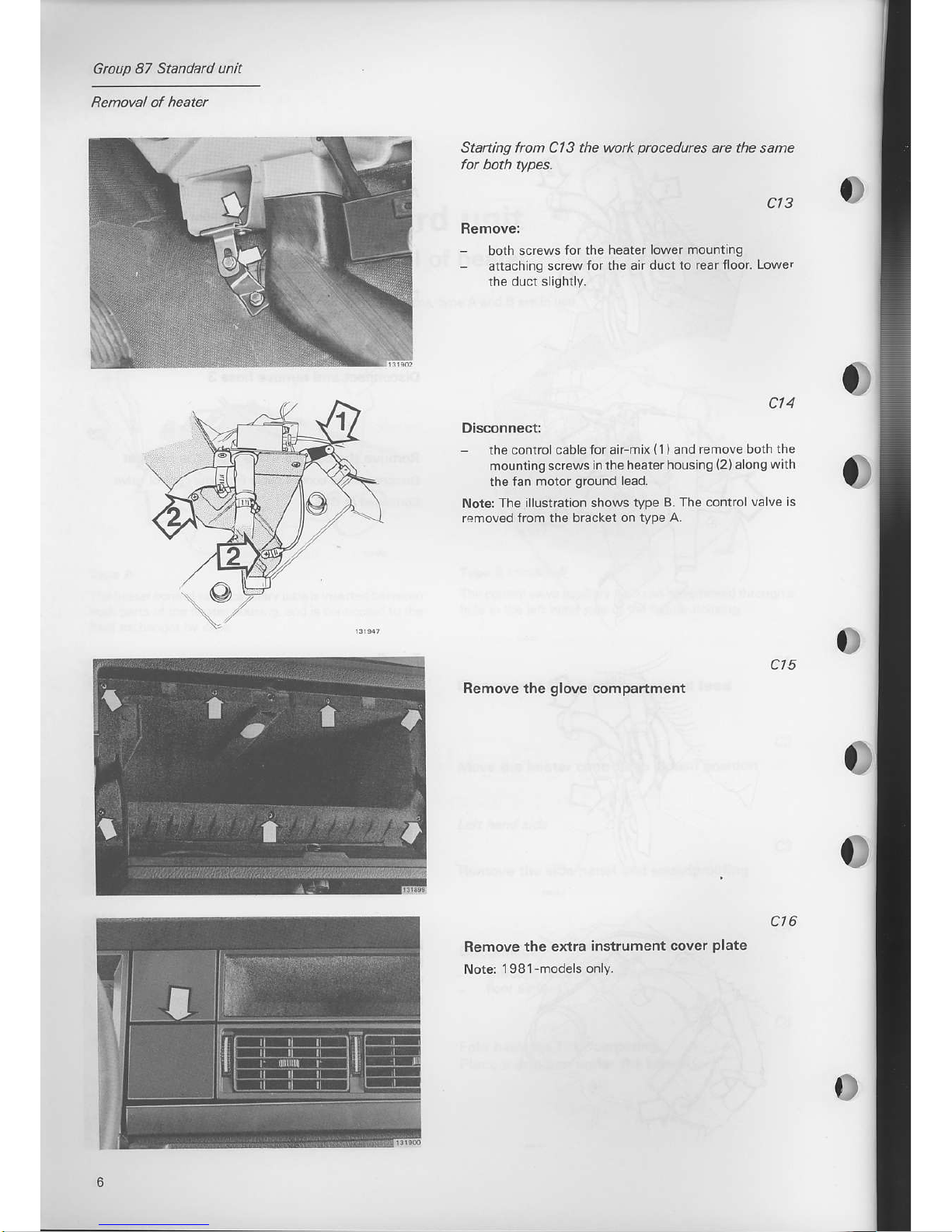
The
heater control
va lve capiLlarv
tube
is insened
between
both
paris
of the
healer housing,
and
rs connectcn
to the
heat exchanger
by
clLps.
Standard
unit
C.
Removal
of
heatel
Note:
Two
differcnt
installations,
tvpe
A and
B are
in 'rse'
0)
Type A
(modifled)
The
control valve
capilla
ry
tube can be
removedthrough
a
hole in the
left
hand side of
the heater
housing
Dlsconn.ct
thc
bettery
ground
lcad
Move
the heater
controls
to closed
Remove
the side
panel
and soundproofing
Disconnectl
-
defroster
hose
ircm the
heater
Fold back
the
floor carpetin9.
Place
a
drip
pan
under
the heater
I
Gtoup
87
Standatd
unit
Removal
of healer
Type
A
Attach
two
hose
pliers:
-
one to
the convolvatve
inter
hose
(t
)
-
the
other
to the heat
erchanger
input hose
(2).
Disconnect
the hoses
1 and 2
as indicated
C7
c6
CB
c9
o
Disconnect
and remove
hose 3
Remove
the control
Disconnect
rhe conrrol
Continued
at Cl3.
valve {rom
the bracket
cable from
the control va ve.
Type
B
cto
Attach a
pair
of hose
pliers
tothe heat
exchanger
inlet hose
cll
Disconnect
the hoses
as indicared
ct2
Remove the heater
control valve
capillary tube
from the
heater housing.
Carefully
pull
out-
Do not remove
the controlvalve
frcm the bracket
)'
Group
87 Standard unit
Removal ol heater
Starting
frcm
Cl 3 the work
procedures
are the same
cl4
Disconnectr
the controlcablefor aiFmix
{1)and
remove both
the
mounting screws
in the heaterhousing
(2)alongwith
the
fan motor
ground
l€ad.
Note: The illustlation shows
type B. The control
valve is
Irmoved from the bracket on
type A.
ct5
Remove the
glove
compartment
ct3
Remove:
-
both
screws for the heater
lower mounting
-
attaching
screw for the ah
duct to rear floor.
Lower
the
duct slightly.
ct6
Remove
the extra
instrument cover
plate
Nots
1981-models only.
Grcup
87 Standa.d
unit
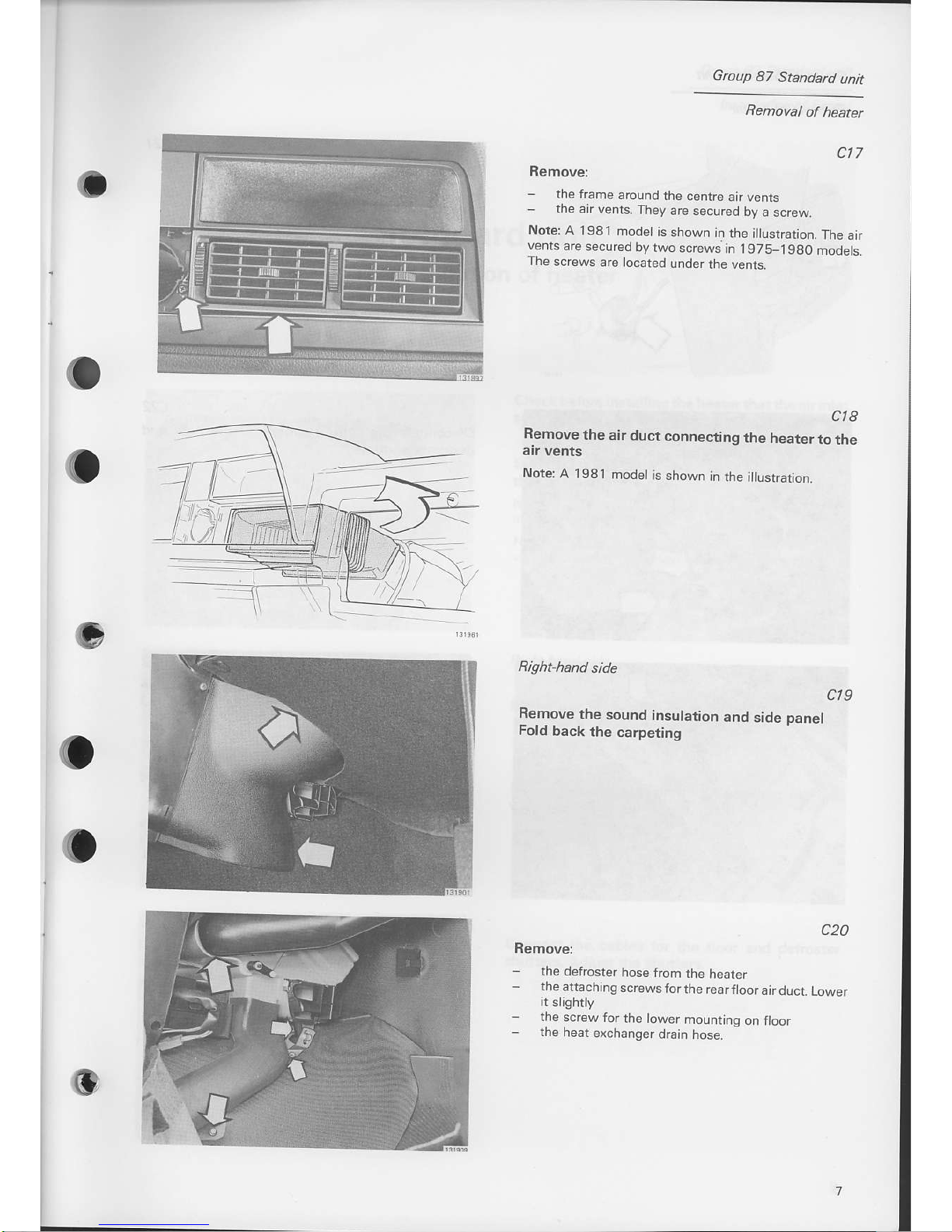
ct7
Remove:
-
the frame
around
the
centre
air vents
-
the ar vents.
They
arc
secured
by
a screw.
Note:
A 1981
modet
is shown
in
the i
ustration.
The
air
vents
are
secured
by two
screws
in 1975_198o
modets.
The
screws
are located
under
the vents.
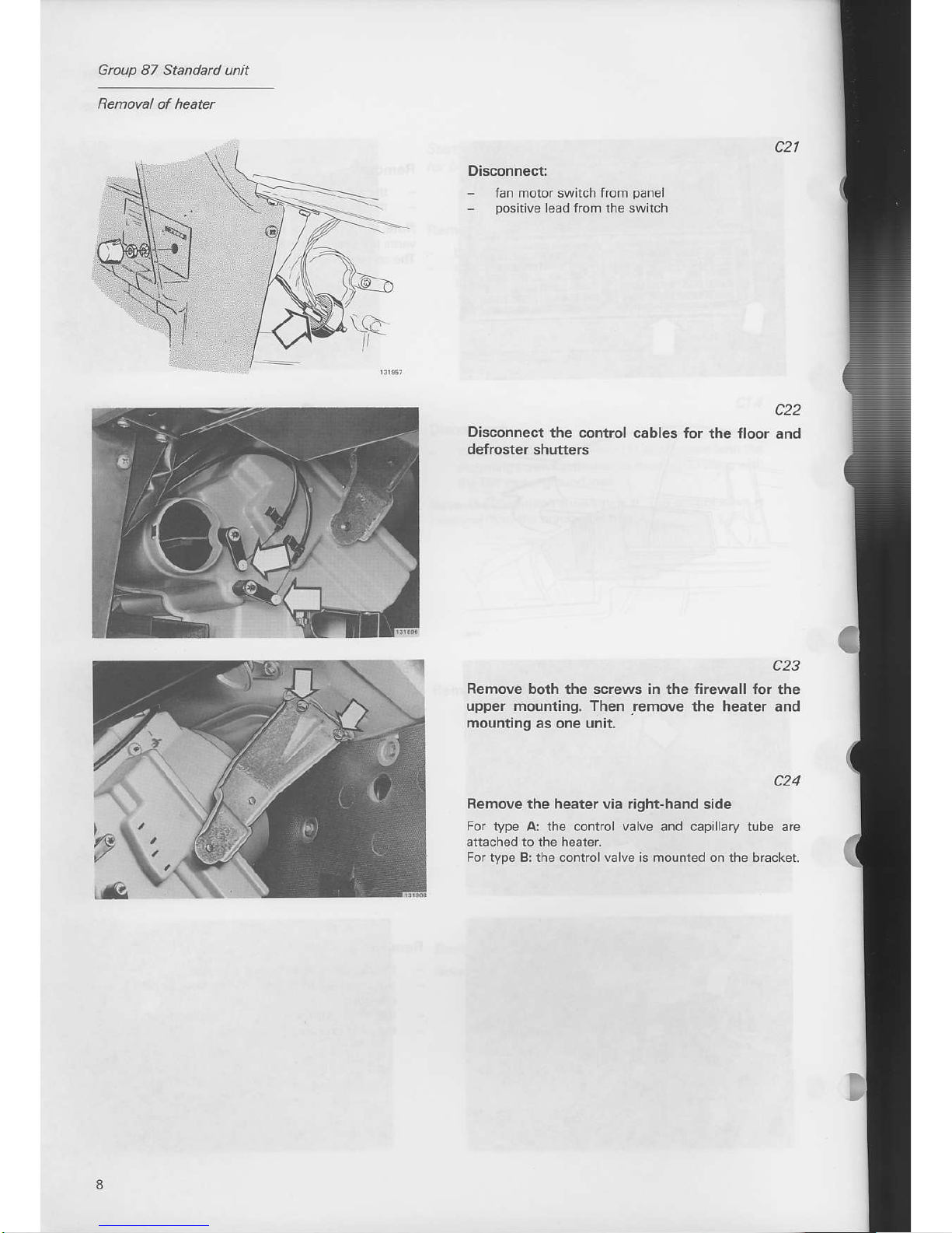
cl8
Remove
the
air duct
connecting
the heater
to
the
Note
A 1981
modet
is
shown
in the
i usrrarion.
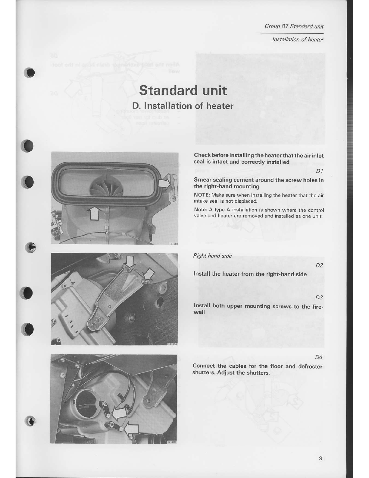
Remove
the
sound insulation
Fold
back
the
carpeting
ct9
and
side
panel
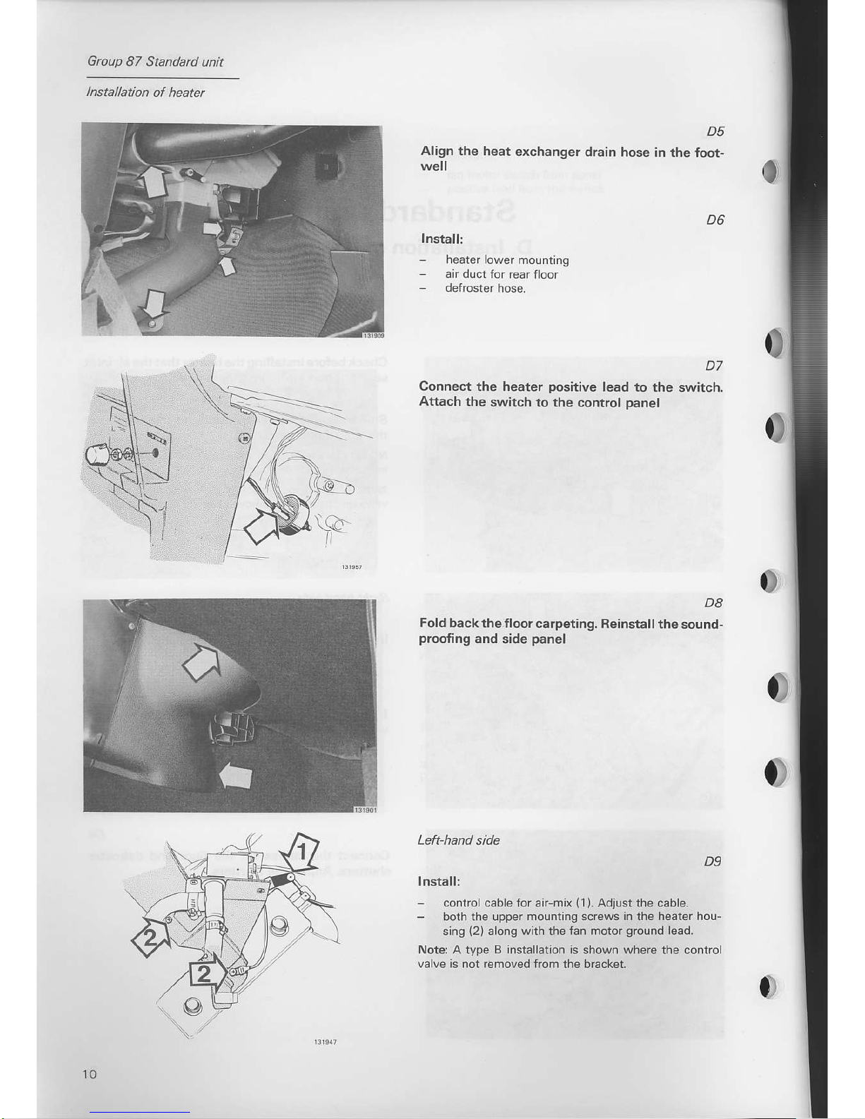
c20
Remove:
-
the
defroster
hose from
the
heater
-
the
attaching
screws
forthe rearftoorairducr
Lower
it
sljghtly
-
lhe screw
for
the tower
mounring
on ftoor
-
the
heat
exchanqer
drain
hose.
..---
Group 87 Standatd unit
Disconnectl
-
fan motor switch from
panel
-
pos
tive
lead from
the swilch
Disconnect
the control
de{roster
shutters
c22
cables for
the
floor
and
c23
Remove both the screws in the firewall for the
upper mounling. Then remove the heater
and
mounting
as one unit,
c24
Remove
the
heater
via right-hand side
For
type Ar the control valve and capillary tube are
attached to the heater
For type B: the controlvalve is mounted on the bracket.
Gtoup 87 Standard
unit
lnstallation
of
heatel
Standard
unit
D. Installation
of
heater
o
o
Check bef
ore
installing
the heaterthatthe
air
inlet
seal is intact
and correcllv installed
DI
Smear
sealing cement around
the screw holes in
the right-hand
mounting
NOTE: lvlake surc when installing
rhe hearer
that the air
intake seal is not displaced.
Nots
A tvpe A installatio.
is shown where the
control
valve
and heater are removed
and installed
as one unit.
Install lhe
heater trom
the right-hand
side
D2
Install both
upper
mounting
wall
D3
screws
to the
fire-
D4
Connect the
cables lor the
floor and
defroster
shutters.
Adjust the
shutters.
Group
87 Standatd
unit
lnstallation
of heatel
Align the heat
exchanger
drain
well
D5
hose in
the foot'
D6
D7
Connect
the heater
positive
lead to the switch.
Aftach the
switch
to the control
panel
lhstall:
-
heater lower
rnountrng
-
air duct for rear
floor
D8
Fold
back the floor carpeting.
Reinsta ll the
sou nd-
proofing
and side
panel
D9
Install:
-
contrcl cable for air-mix
{1).
Adjust the cable.
-
both the upper mounting screws
in
the
h€ater hou-
sins
(2)
along
with
the
fan motor
ground
lead.
Nots A type B installation is shown where the control
valve is not removed from the bracket.
10
Group
87 Standard
unit
lnstallation
of heatel
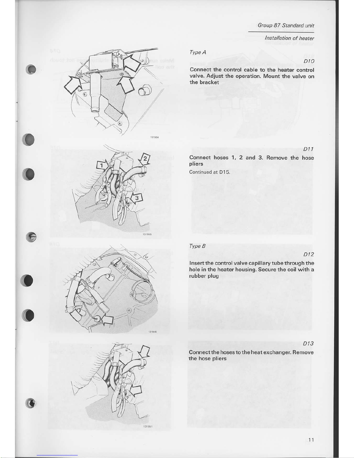
Type
A
Connect the
valve. Adjust
the bracket
Dl0
control
cable to the heater
control
the
operation, Mount the valve
on
Dl
.l
2 and 3. Remove
the hose
o
i
Connect hoses
1,
pliers
Continued
at
D15.
Type B
Dt2
Insert the controlvalve capillarytube through the
hole in the heater housing. Secure the coil with a
rubber
plug
Dt3
Connectthe
hosestothe heatexchanger,
Remove
the hose
pliers
Group 87 Standard unit
lnstallation of heater
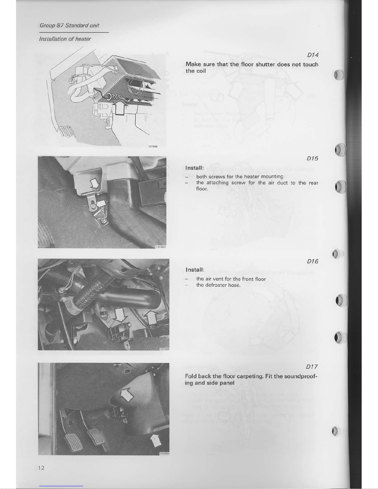
D|4
Make
sure that the Jloor shutter does not touch
the coil
Dt5
lnstall:
-
both screws
for the heater
mounting
-
the attaching
screw for the air duct to the rear
0
Dt6
lnstallr
-
the air vent
for the front floor
-
the defrcster
hose.
Dt7
Fold back the floor carpeiing. Fitthe soundprcofing and
side
panel
0
12
Group
87
Standad
unit
lnstallation
of
heater
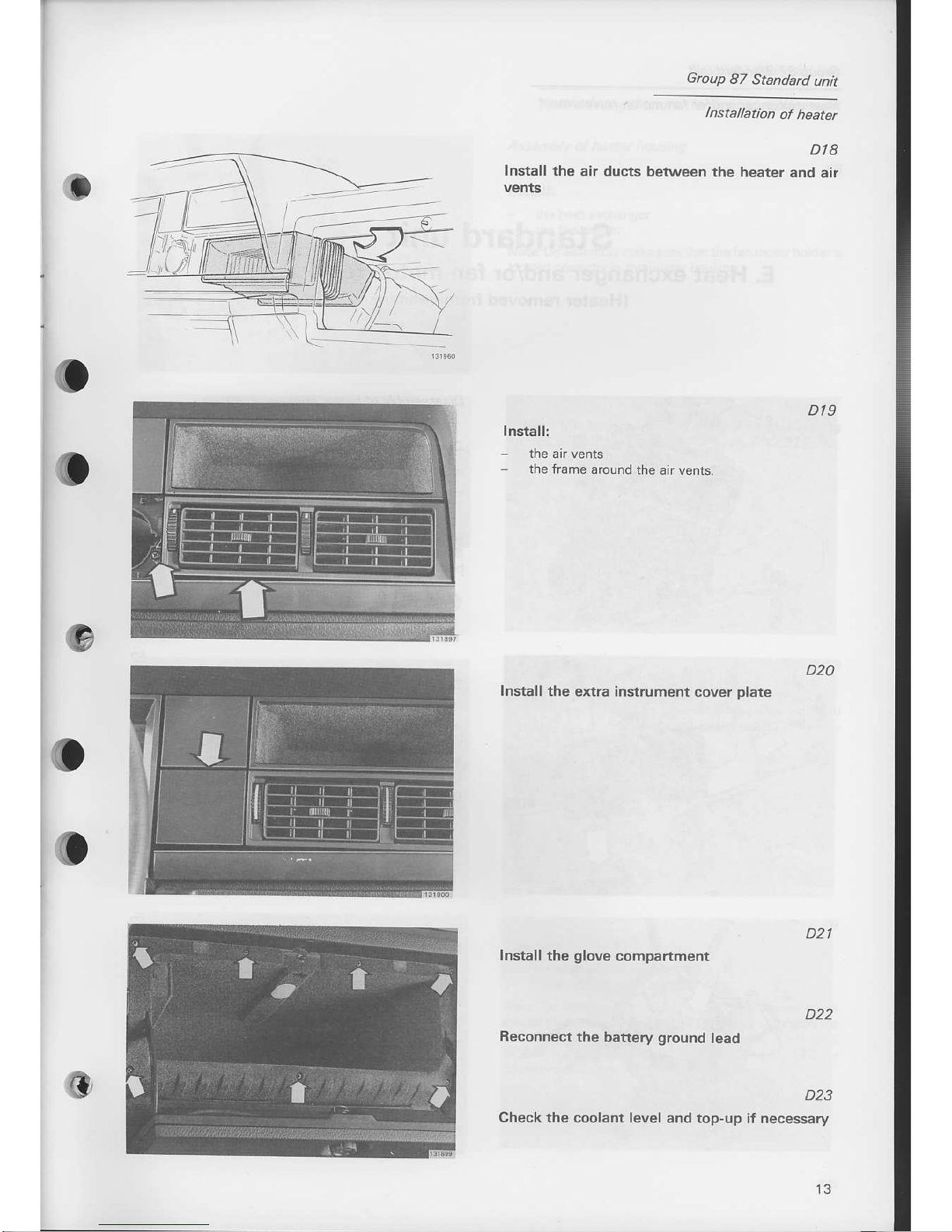
D18
Install
the air ducts
betwo€n the
heater and
air
Dt9
Install:
-
the
fram€ around
the air vents.
D20
Install
th€ 6xtra instrument
cover
Dlate
Install
the
glove
compartment
D22
R€connect
tho
battery
ground
lead
D23
Check the coolant level
and top-up if necessary
D2l
Group
87 Standard
untt
Heat exchanger
and/or
fan motoL
rcplacement
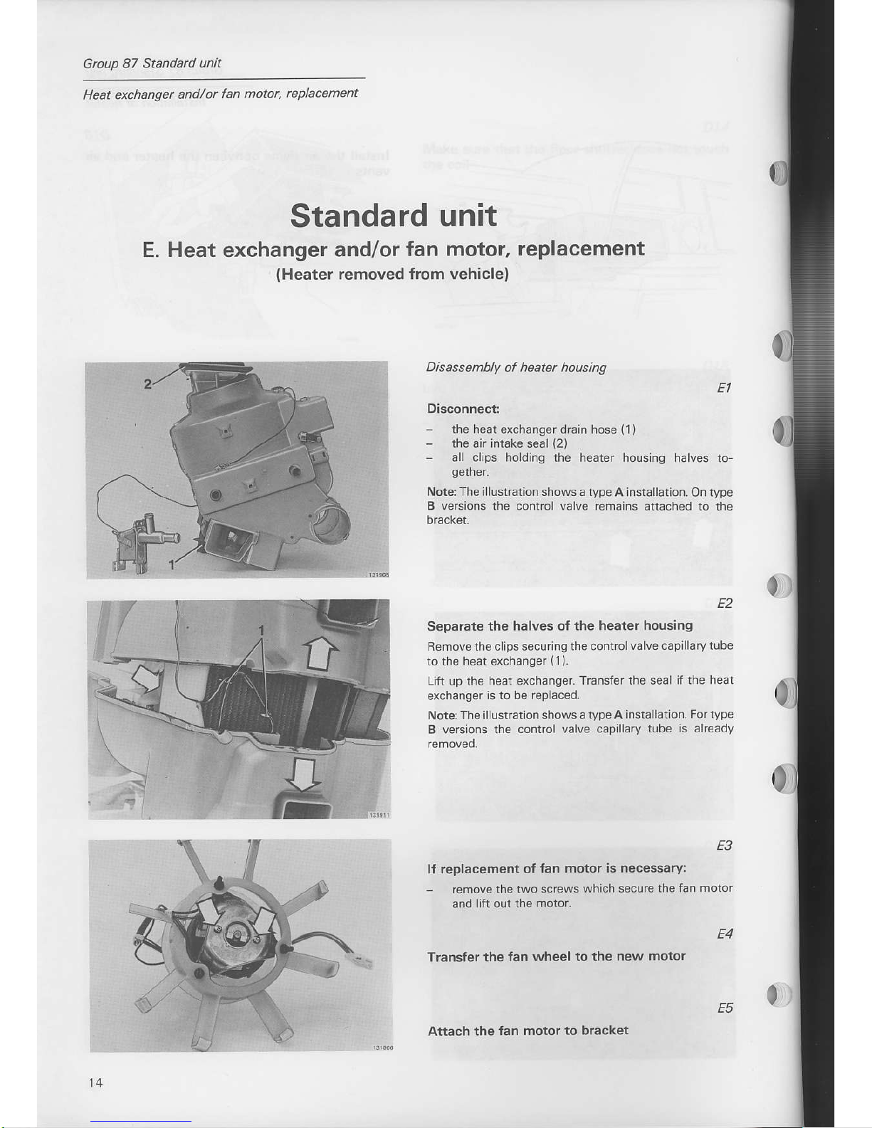
Disassembly of heatet housing
Disconnect:
-
the heat exchanger drain hose
-
the air intake seal
(2)
-
all cips
holding
the heater
(t)
housing halves to
Note The
i llstration
shows a type A nsta latlon.
On type
B versions the control valve remains
attached to the
replacement of
fan motor
is necessary:
remove the
two screws which
secure the fan
motor
and
lift out the
motor.
Separate
the halves of the
heater housing
Removethe
clips securing the controlvalve
capilary tube
to the
heal exchanger
(1).
Lrft up the heat exchanger.
Transfer the seal
if
the
hest
exchanger
is to be replaced.
Note:The
illustraton shows a
type A instalat on.
For
type
B
versons the controi valve caplary
tlbe is already
ff
Transter the
{an wheel to the
new motor
14
Standard
unit
E. Heat exchanger
and/or fan
lHeater removed
from
motor, replacement
vehicle)
Attach the fan
motor to bracket
E4
Gtoup
87 Standatd unit
Heat exchanger and/or
fan motor, rcplacement
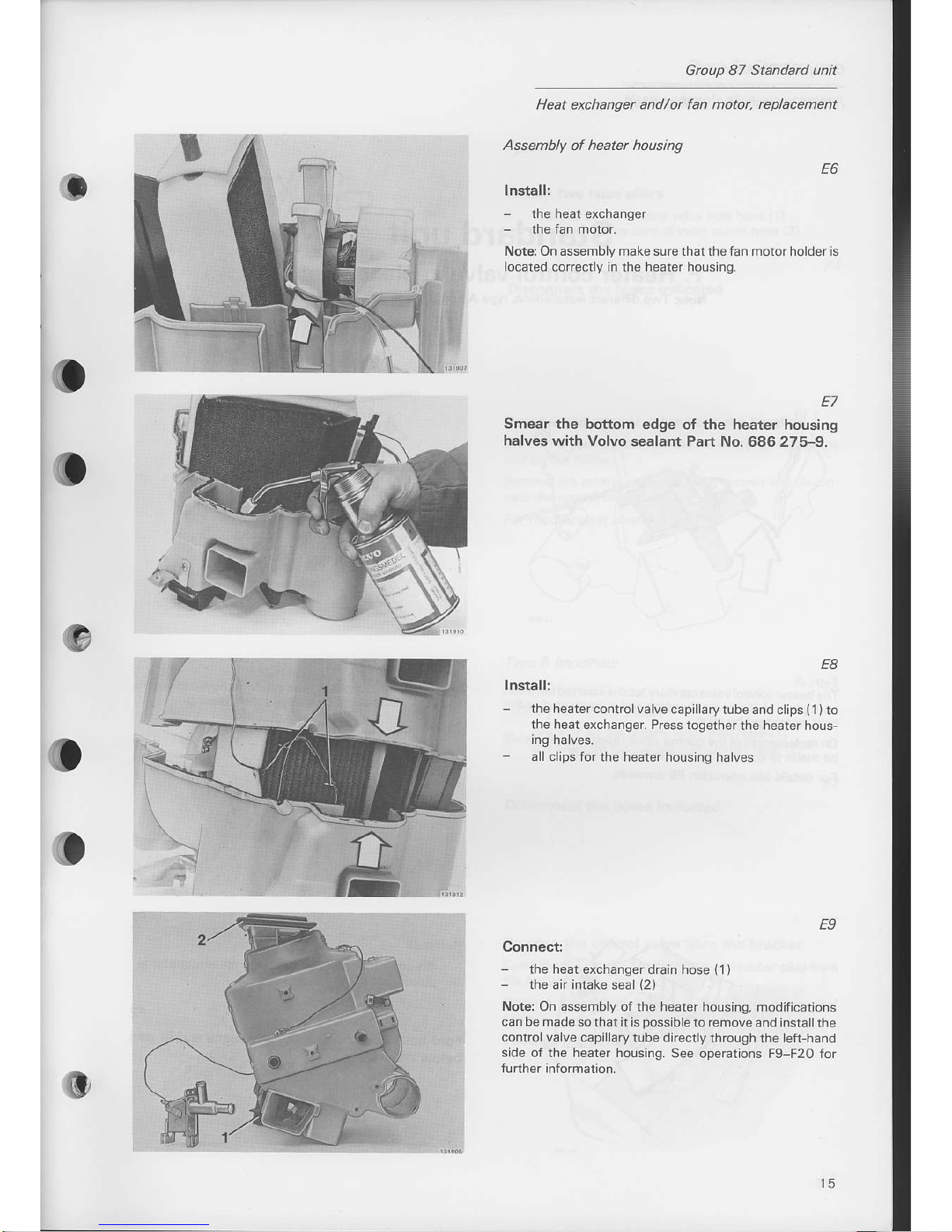
Assembly of heatet housing
E6
lnstall:
-
the heat exchanger
Nota On assembly makesure thaithefan motorhold€ris
ocated corectly in
the
heater hor.rsing
Smear
the bottom edge
halves
with Volvo sealant
E7
oI
the heater
housing
Pan
No. 686 275-9.
E8
Install:
-
the heater control
valve cap llaryrubeand
clips
(1)to
ihe heat
exchanger. Press iogether
the heater ho!s
ing halves.
3ll c ips forthe
heater housing halves
E9
Connectl
the heat exchanger drain hose
(1)
the
air intake seal
(2)
Noter
On assembly of the he.ter housing,
modifications
can be made so that it is
possib
e to
remove
and inst.llthe
controlva ve capillarytube directly
through the left-hand
side of lhe heater housing.
See operations F9-F20 ior
0,
l5
Group 87
Standad unit
heater contrcl valve. replacement
Standard
unit
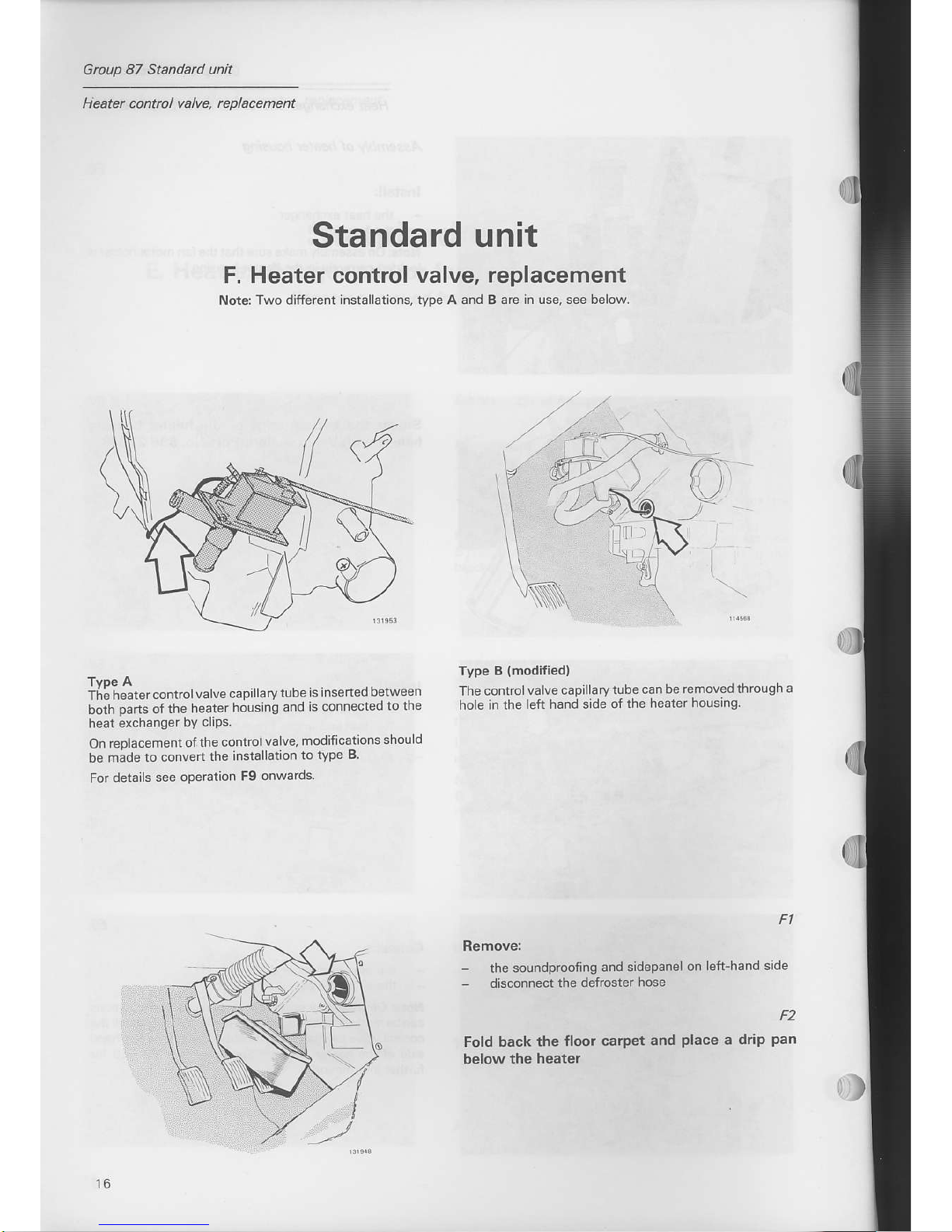
F. Heater control valve,
Notq Two different instalations.
tvDe A and
replacement
B are in use, see below.
The heare'
con trol
va lve capillarvlube
is nserlpd
betweFn
both
parts
of the
heater
housing
and
is connected
to the
heat exchanger
by clrps.
On replacement
ofthe
controlvalve,
modifications
shou ld
be made to convert
the
installation
to tvpe
B
For
details see
operation
F9 onwards
Type
B
{modified}
Thecontrolvalve
capillarytube
can
be removed thlough
a
ho e in the
left hand side
of the
he.ter housing
Remove:
-
the soundproofing
and sidepanel
on
left-hand side
-
disconnect
the defroster
hose
F2
Fold back
the floor carpet
and
place
a drip
pan
below
the healer
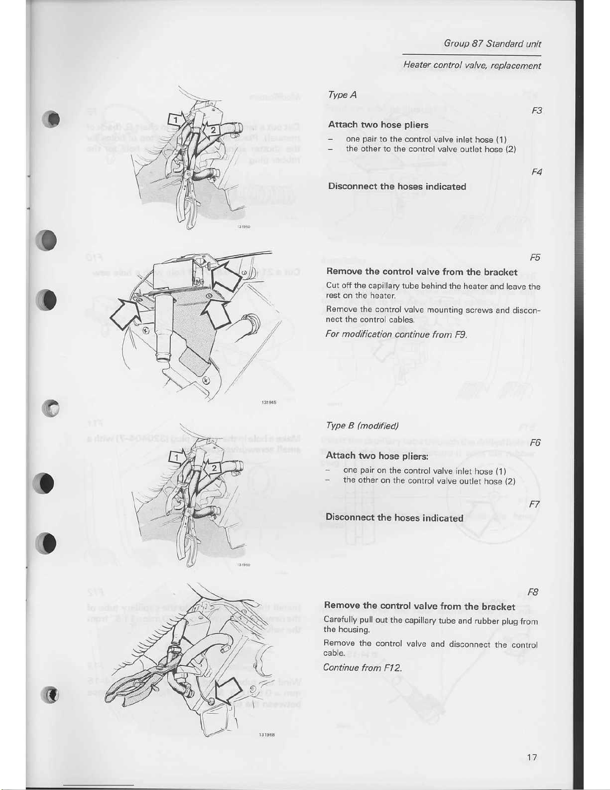
Type
A
Attach two hose
pliers
-
one
pair
to the control valve
inlet hose
(1)
-
the orher to rhe controlvalve
ouder hose
(2)
Disconnect
the hoses
indicated
F5
Remove
the control valve
Jrom the bracket
Cut off the
capillary tube behind
the heaterand teave
the
Remove
the control
valve mounring
screws and
discon
nect the
control cables.
Fot modiflcation
continue
frcm K).
Type
B
(modif
ied)
Attach
two hose
pliers:
-
one
pair
on
the controtvalve
jntet
hose
(1/
-
the
other on
rhe controtvatve
outtet
hose
(2)
Disconnect
the hoses
indicated
Group
87 Standard
unit
Heater control
vafue,
rcplacement
F8
Remove
the control
valve
trom
the bracket
Carefully
pulloutthe
capillary
tube and
rubber
plug
from
Remove
the
control valve
and disconnect
the
control
Continue
from
Fl2.
Group
87 Standard unit
Heater
contrcl valve.
rcplacement
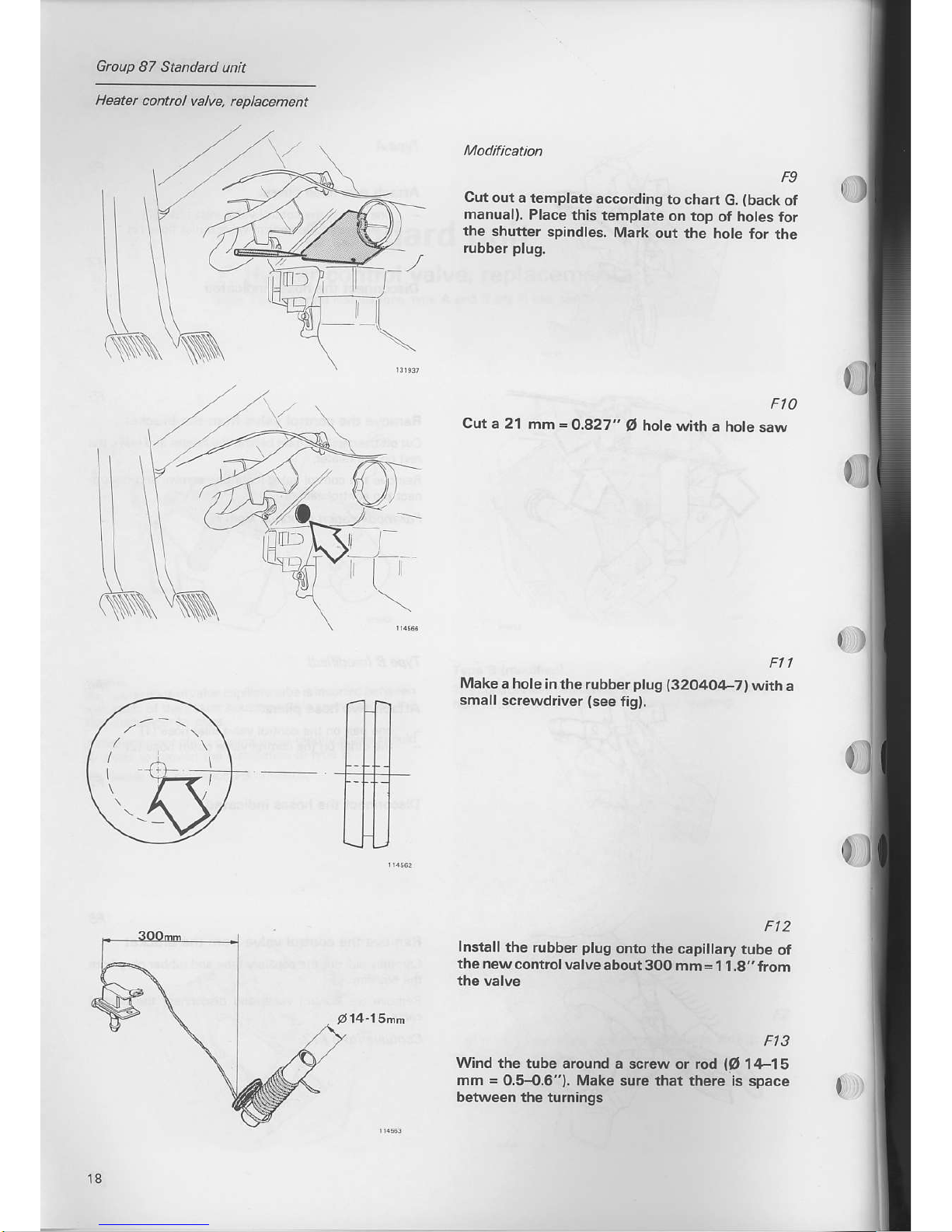
F9
Cut out
a template
according
to chan
G.
(back
of
manuall.
Place this
template
on top
o{ holes for
the
shutter spindles.
Mark
out the
hole {or
the
rubber
plug.
Fto
Cut a
21 mm
=
0.827"
O
hote
with a hote
saw
Make
a hole
inthe rubber
plug
{32040,1-7)wirh
a
small screwdriver
(see
tig).
Ft2
Install
the
rubber
plug
onto the
capillary tube
of
the new
controlvalve
abour300
mm=1 1.8,,
from
the valve
Ft3
Wind the lube
a.ound a screw or rod
lO
14-15
mm
=
0.5-O.6r'). Make surc that
there is space
beNveen the turnings
l8
14-15hn
Group 87
Standad
unit
Heater
contrcl valvq
replacement
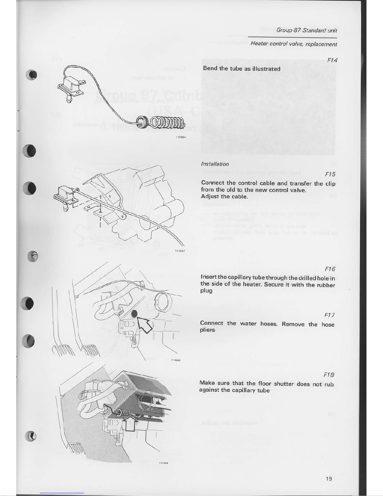
Bend
the tube
as illustrated
Ft5
Connect
the control
cable and
transter the
clip
lrom the
old to the
new control
valve.
Adiust
the cable.
Ft6
Insertthe
capillarytubethrough
the drilled
hole in
the
side
oI the heater.
Secure
it with
the rubber
ptug
Connect
the
water
hoses.
Bemove
the nose
pliers
o
G
Make
sure
that the
floor
against
the
capillary
tube
Fta
shufter
does not
rub
o
-l-
I
i
Group 87 Standad unit
Heater
control vafue. replacement
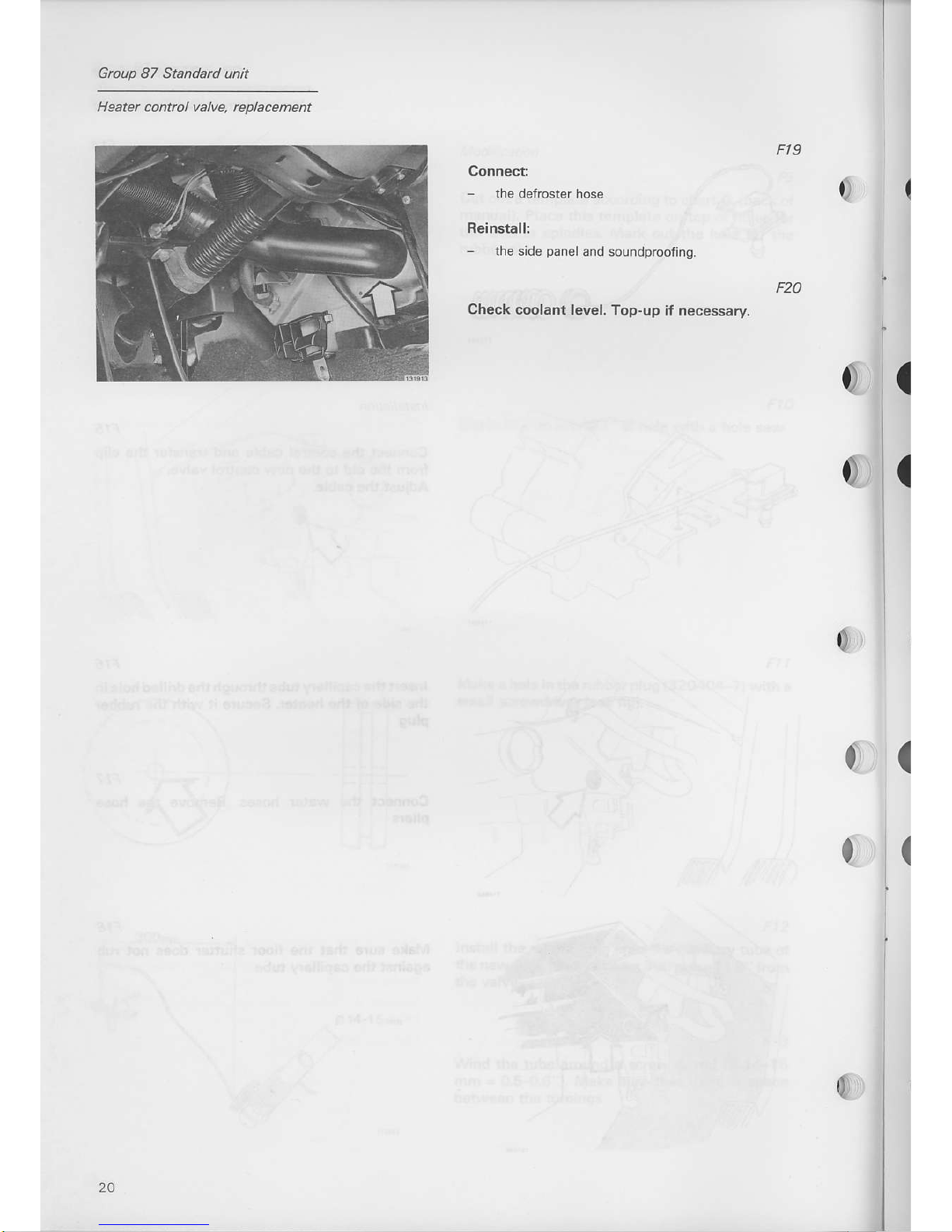
Ft9
Connect:
-
the defroster
hose
Reinstall:
-
the side
paneland
soundproofing.
Check coolant level,
Top-up if necessary.
(
0,
0)
{
l
 Loading...