

Page 1
Sp ec if ic at io ns
4
Model VIVA 30
CAP ACITY
INP UT
Vol tage
Vol tage R ang e
OUT PUT
Vol tage R egu lat ion (I nv. Mod e)
Wav efor m
BAT TERY
Ba tter y Type & Nu mbe r
Flo ati ng Ch arg e Volt age
Typi cal Re cha rge T ime
PHY SICAL
Dim ens ion ( DxW xH mm)
(@ ve rti cal ly st and)
Net W eig ht (kg s)
30 W
228 x 8 2.5 x 2 07
2.7 3 .1
13. 7V ±1 .5%
4 hou rs re cov er to 90 % cap aci ty
230 V AC
100 -30 0 VAC
160 -23 0 VDC + /-1 0%
DC Ou tpu t
12 V 7 Ah x 1 1 2 V 9 Ah x 1
2
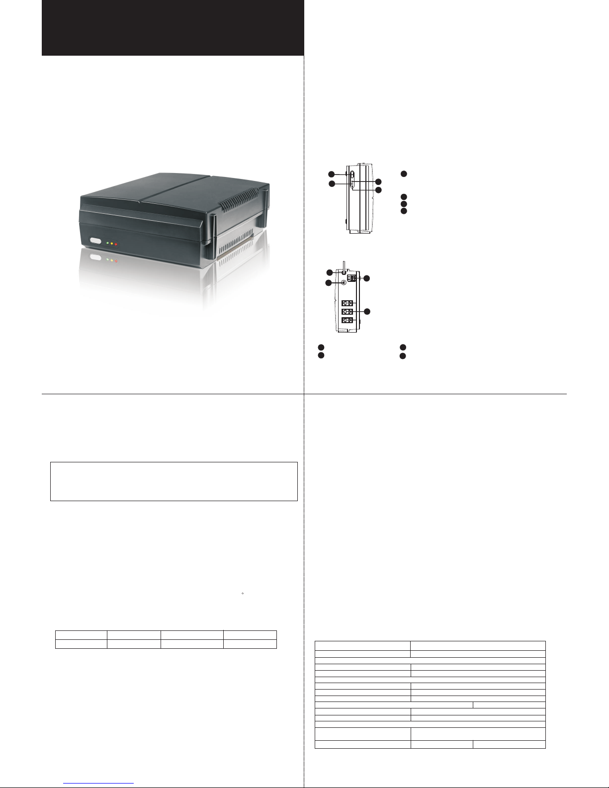
Pr od uc t Ov er vi ew
Front Vi ew:
Back Vie w:
1
2
3
4
Ou tpu t rec ept acl es
AC i npu t Extern al ba tte ry co nne cto rs
Input fuse
3
4
1
2
Quick Guide
V.1.0
Viva Inverter
In tr od uc ti on
VI VA is a co mpa ct in ver ter d esi gned to powe r
It s por tab le si ze fe atu res e asy i nst all ati on an d hig h mov abi lit y. It’ s per fec t for
divers e app lic atio ns fr om in doo r to out doo r eve nts or acti vit ies s uch as c amp ing
and nigh t mar ket s.
Bes ides, it can a cce pt wi de inp ut vo lta ge ra nge. I t’s p erf ect to use in u nst abl e powe r
are a. It al so of fers fle xib le di spl ay ways: vert ica lly s tan d, fl atl y dis pla y, and t wo-
di rec tio n mou nti ng. I t’s very easy t o ins tal l at ho me, o ffi ce, o r car ry ou tsi de.
Co mpar ed to h eav y-duty in ver ter s, it’ s a cos t-e ffe ctiv e sol uti on for ligh tin g.
en erg y sav ing b ulb s up to 3 -4 ho urs .
1
3
Before u sin g the u nit , ple ase r ead a ll in structions a nd ca uti ona ry
markin gs on t he un it, t his m anu al an d the b atterie s.
Im po rt an t Sa fe ty W ar ni ng s
Gener al Pr eca ution-
Conven tio ns us ed:
WARNIN G! Wa rni ngs i den tif y con dit ion s or pr act ice s tha t cou ld re sul t in persona l
injury;
CAUTIO N! Ca ution identify condit ion s or pract ice s tha t cou ld re sul t in da mag ed to
the unit or ot her e qui pme nt co nne cte d.
CAUTIO N! Th is unit cont ain s mor e tha n one l ive c irc uit ( bat ter ies & A C lin e). P owe r
may b e pre sent at more than o ne so urc e. To red uce t he ri sk of e lec trical
shock, dis con nec t bot h AC an d DC po wer f rom t he un it be for e att emp tin g
any m ain tenance or repl ace men t ins ide o f the u nit . Turn ing o ff th e uni t
will no t red uce t his r isk .
CAUTIO N! To re duc e ris k of in jur y, onl y use q ual ifi ed ba tte rie s fro m qua lif ied
distribu tor s or ma nuf act ure rs. A ny un qua lif ied b att eri es ma y cau se
damage and i nju ry. Do NO T use o ld or o ver due b att eri es. P lea se ch eck
the battery type and date code b efore insta lla tio n to av oid d ama ge an d
injury.
WARNIN G! It 's ve ry im portant for sys tem s afe ty and efficient o peration to u se
appropriate e xte rna l bat ter y cab le. To re duc e risk of inju ry, ext ern al
battery cable s sho uld b e UL ce rti fie d and r ate d for 7 5 C or hi ghe r. And
do NOT use c opp er ca ble s less than 18 AWG. B elow is the ex ter nal b att ery
cable reference according to sy ste m req uir eme nts .
Mo del Typ ica l Amp . 1-4 F eet ( one -way) Dia-m m
VI VA 30 3 A AWG 14 1.6 277
Table 1 Mi nim um Re com men ded B att ery C able Size v ers us Le ngt h
WARNIN G! Pr ovi de ve nti lat ion to outdo ors f rom t he ba tte ry co mpa rtm ent . The
battery enclo sur e sho uld b e des ign ed to p rev ent a ccu mul ati on an d
concentra tion of hy dro gen g as at the top of the co mpa rtm ent .
CAUTIO N! Us e insulate d too ls to r edu ce th e cha nce o f sho rt- cir cui t whe n ins tal lin g
or work ing w ith t he in ver ter, the batter ies , or ot her e qui pme nts a tta che d
to this unit .
CAUTIO N! Fo r bat ter y ins tal lat ion a nd maintenanc e, re ad th e bat ter y man ufa ctu rer 's
installa tio n and m ain ten anc e ins tru cti ons p rior to opera tin g.
1
3
4
Pow er sw itch
St atu s ind ica tor s
(p lea se se e the O per ati on se cti on fo r the d eta ils )
Li ne mo de/ Cha rgi ng mo de in dic ato r - gre en LE D
Inv ert er mode indi cat or - Yel low L ED
Al arm i ndi cat or - Re d LED
1
2
3
4
2
Perso nne l Pre caution -
CAUTIO N! If y ou ne ed to r emo ve a ba tte ry, ma ke su re al l acc ess ori es ar e off s o
you d on’t ca use a s par k.
CAUTIO N! Ma ke su re th e are a aro und t he batte ry is wel l ventil ate d.
CAUTIO N! Ca ref ul to r edu ce th e risk or droppin g a met al to ol on t he ba tte rie s.
It could spa rk or s hor t cir cui t the b att eri es an d cou ld ca use a n exp losion.
CAUTIO N! Re mov e per son al me tal i tem s such as ring s, bra celets, ne ckl ace s, an d
wat ches when wo rki ng wi th ba tte rie s. Ba tte rie s can p rod uce a s hor t
circuit curre nt hi gh en oug h to ma ke me tal m elt , and c oul d cau se se ver e
burns.
CAUTIO N! Av oid t ouc hin g eye s whi le wo rking near b atteri es.
CAUTIO N! Ha ve pl ent y of fr esh w ate r and s oap n ear by in c ase batt ery acid con tac ts
skin, clot hin g, or e yes .
CAUTIO N! NE VER smoke or allo w a spa rk or f lam e in vi cin ity o f a bat ter y.
CAUTIO N! If a r emo te or automa tic g ene rator st art s yst em is u sed , dis abl e the
automati c sta rti ng ci rcu it or d isc onn ect t he ge ner ato r to pr eve nt
accident duri ng se rvi cin g.
Page 2
5
In st al la ti on
NOTE: Before insta lla tio n, pl eas e ins pec t the u nit . Be su re th at
no thi ng in sid e the p ack age i s dam age d.
IMPORTANT W ARN ING S BEF ORE M AKI NG BA TTERY CONNEC TIO N!!
CAUTIO N!! R emo ve pe rso nal m eta l ite ms su ch as rings, b race lets, neck lac es, a nd
wat che s when worki ng wi th ba tte rie s.
CAUTIO N!! F or th e use r ope rat ion s afe ty, we strongl y rec omm end t hat y ou sh oul d
use tapes to i sol ate t he ba tte ry te rmi nal s bef ore y ou st art t o ope rat e the
unit. Plea se re fer t o bel ow in str uct ion f or fu rth er in for mat ion .
St ep 1-Tur n off t he un it an d unp lug t he unit to prevent electr ica l sho ck or s par ks.
St ep 2- Remove 4 sc rew s located on t he bo tto m of th e uni t to op en th e uni t. To pre ven t
any s hocks, ple ase d o NOT to uch any in side compo nen ts.
St ep 3- Che ck if t her e is an i nte rna l bat ter y ins ide . If ye s, re mov ing b att ery w ire s fro m
inter nal b att ery f irs t.
NOTE: Do N OT ma ke th e bat ter y sho rt ci rcu ite d, or i t will ca use t he da nge r of
burning. To pr eve nt an y sho cks , do NO T tou ch an y ins ide c omp one nts .
A. Repla ce In ter nal B att ery
St ep 1- Remove th e old batt ery from t he case.
St ep 2- Mak e sur e the n ew ba tte ry is t he sa me ty pe an d nom ina l vol tag e to th e old
battery.
St ep 3- Con nec t the b att ery c abl es to t he in ter nal b att ery.
RED cabl e to th e pos iti ve te rmi nal ( RED) of the batt ery ;
BLACK ca ble t o the n ega tiv e ter min al (BLACK ) of th e bat ter y.
St ep 4-A ssemble th e cas e wit h 4 scr ews .
St ep 5- Power on the un it.
B. Modif y Int ern al Ba tte ry Co nne cti on to External B att ery C onn ect ion
St ep 1- Remove th e old batt ery from t he case.
St ep 2- Con nec t bat ter y cab le to e xte rna l bat ter y ter min al on PCB.
RED cabl e to W7 : t he po sit ive t erm ina l (RED+)(BAT +);
BLACK ca ble t o W5: t he ne gat ive t erm ina l(BLK-)(BA T-)
St ep 3-A ssemble th e cas e wit h 4 scr ews .
St ep 4- Follow the proce dur es of E xternal Batt ery C onn ect ion S ect ion l ist ed be low .
St ep 5-A fter compl eti ng ex ter nal b att ery c onn ect ion , pow er on t he un it.
C. Modif y Ext ern al Ba tte ry Co nne cti on to Inter nal B att ery C onn ect ion
St ep 1- Bef ore d isa sse mbl ing t he un it, d isc onn ect the exte rna l bat ter y and e xte rna l
battery cable f irs t.
St ep 2- Dis ass emb le th e uni t.
St ep 3- Dis con nec t the i nte rna l bat ter y cab le fr om th e ext ernal battery term ina l
(W5 and W 7).
St ep 4- Put i nte rna l bat ter y int o the c ase . Mak e sur e the v olt age o f the n ew ba tte ry is
equal t o the n omi nal b att ery D C vol tag e of th e uni t.
Intern al Ba tte ry Se cti on
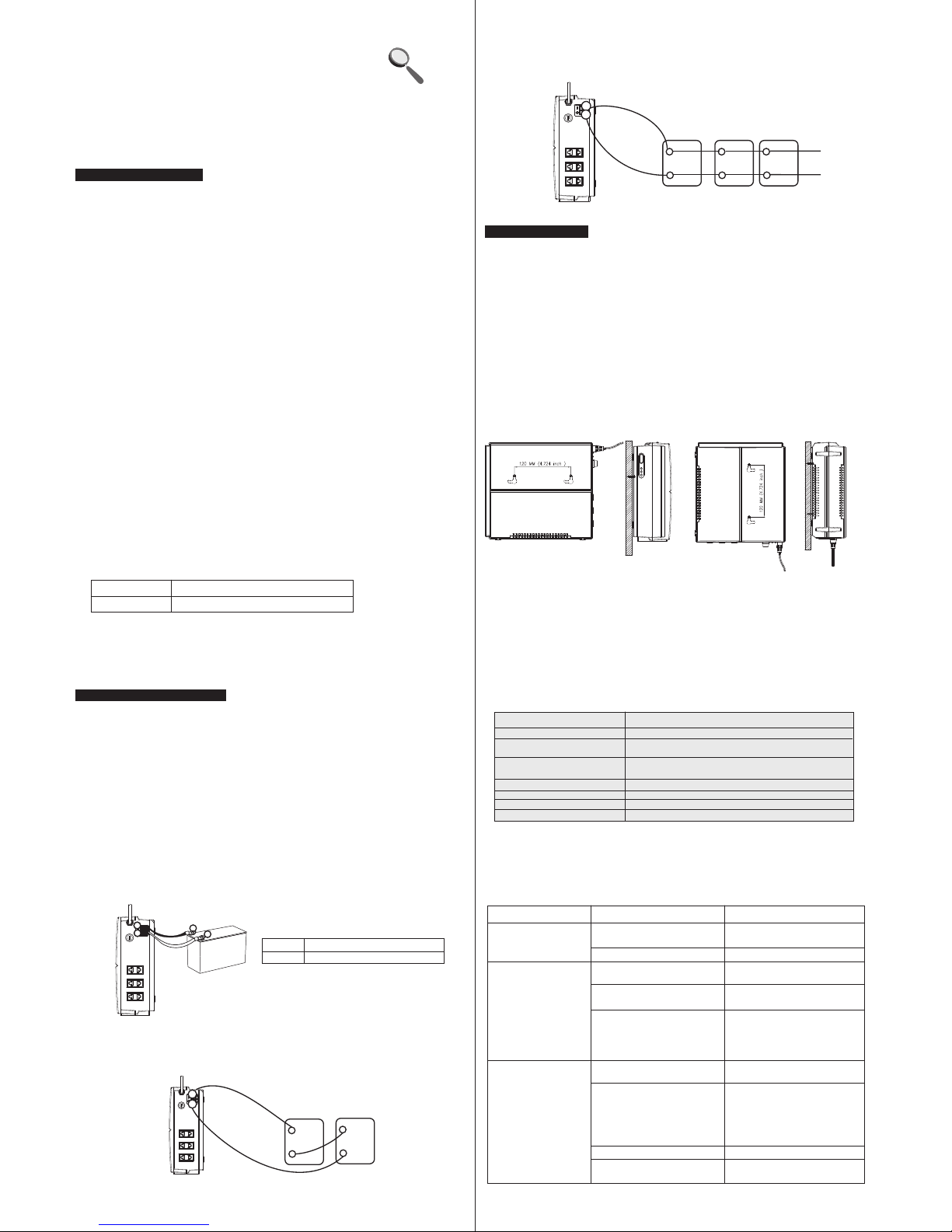
Mounti ng th e Uni t
Th e uni t can b e mou nte d to a wa ll su rfa ce in t wo wa ys. P lea se fo llo w bel ow st eps :
1. Tur n off t he un it be for e mou nti ng.
2. S ele ct an a ppr opr iat e mou nti ng lo cat ion a nd mo unting met hod .
Method 1 :
St ep 1: U se a ho riz ont al li ne an d the l eng th of t he li ne mu st be 120 mm and mark t he
two end s on th e wal l. (s ee ch art 1 )
St ep 2: D ril l two m ark s by sc rew s.
St ep 3: M oun t the u nit b y pos iti oni ng th e key -ho le sl ots o ver t he mo unt ing s cre ws.
(see ch art 2 )
Method 2 :
St ep 1: U se a ve rti cal l ine a nd th e len gth o f the l ine m ust b e 120 m m and mark the
two end s on th e wal l. (S ee ch art 3 )
St ep 2: D ril l two m ark s by sc rew s.
St ep 3: M oun t the u nit b y pos iti oni ng th e key -ho le sl ots o ver t he mo unt ing s cre ws.
(see ch art 4 )
Op er at io n
6
Power On /Of f
On ce th e invert er ha s bee n pro per ly in sta lle d, pr ess t he po wer s witch to tur n on th e
un it. T he un it wi ll wo rk au tom ati cal ly in line mode or inverter mode a cco rdi ng to i npu t
ut ili ty po wer 's st atu s. Wh en pr ess t he po wer s wit ch again, the uni t wil l be tu rne d off.
LED Indicat ors
Th ere a re th ree i ndi cat ors ( Gre en/ Red /Yel low ) in th e fro nt pa nel o f the u nit .
Sta tus Ind icato r
Ful l batte ry at L ine m ode.
Cha rgi ng ba tter y at Li ne
mod e
Nor mal b att ery vo lta ge at
Inv ert er mo de.
Low b att ery a t Inve rte r mod e.
The o utput i s short -circ uited .
The u nit i s ove rloa d.
The u nit is ov er char ged.
Gre en LED li ghtin g.
Gre en LED fl ashin g every 3 s econd s.
Yell ow LED l ight ing.
Yell ow LED f lash ing eve ry 2 seco nds.
Red L ED ligh ting.
Red L ED flas hing fo r 0.5 sec ond eve ry seco nd.
Red L ED flas hing ev ery 5 sec onds.
Tr ou bl e Sh oo ti ng
7
Us e the t abl e bel ow to s olv e min or pr obl ems .
Proble m Pro bab le Ca use S olu tio n
Ut ili ty po wer i s
no rma l but t he un it
is i n inve rter mo de.
Wh en po wer f ail s,
th e bac kup t ime i s
sh ort en.
No L ED di spl ay on
th e front pa nel w hen
th e uti lit y pow er is
no rma l.
AC i npu t pow er co rd is n ot
co nne cte d wel l.
Input fuse is blo wn.
Th e uni t is overl oad .
Ba tte ry vo lta ge is t oo lo w.
Ba tte ry ca pac ity i s not f ull
even af ter c har ge th e uni t
for at least 8 h our s.
Th e uni t is no t tur ned o n.
Ba tte ry is n ot co nne cte d
we ll.
Ba tte ry de fec t.
Ba tte ry vo lta ge is t oo lo w.
Ch eck A C inp ut po wer
co nne cti on.
Rep lace the input fuse.
Rem ove s ome n on- critical
lo ads .
Ch arg e the u nit a t lea st
8 ho urs .
Ch eck t he da te co de of t he
ba tte ry. If th e bat ter ies
are too o ld, r epl ace t he
ba tte rie s.
Press p owe r swi tch t o tur n
on t he un it.
Ch eck t he ex ter nal b att ery
ca ble a nd te rmi nal . Mak e
su re al l the b att ery
co nne cti ons t o the u nit a re
al l cor rec t.
Rep lace the batteries .
Ch arg e the u nit a t lea st
8 ho urs .
If t her e is any abn orm al si tua tio ns oc cur, wh ich d oes n't l ist a bov e, pl eas e cal l the
se rvi ce pe opl e imm edi ate ly fo r pro fes sio nal e xam ine .
St ep 5- Con nec t the b att ery c abl e to th e int ern al ba tte ry.
RED cabl e to th e pos iti ve te rmi nal ( RED) of intern al ba tte ry;
BLACK ca ble t o the n ega tiv e ter min al (BLACK) of in ter nal b att ery .
St ep 6-A ssemble th e uni t wit h 4 scr ews .
St ep 7- Power on the un it.
St ep 1- F ollowing bat ter y pol ari ty gu ide p rin ted near the bat ter y ter min al!
Place t he ex ter nal b att ery c abl e rin g ter min al ov er th e bat ter y ter min al.
RED cabl e to th e pos iti ve te rmi nal ( +);
BLACK ca ble t o the n ega tiv e ter min al (-).
St ep 2- T igh t the s cre ws. D o NOT p lac e any thi ng be twe en th e fla t par t of ba tte ry
termi nal a nd th e bat ter y cab le ri ng te rmi nal , or ov erh eat ing m ay oc cur.
St ep 3- C onn ect b att ery c abl es to t he ex ter nal b att eri es.
Note: Fo r the u ser o per ati on sa fet y, we st ron gly r eco mme nd th at yo u sho uld u se ta pes
to i sol ate t he ba tte ry te rmi nal s bef ore y ou st art t o ope rat e the u nit .
1)Sing le ba tte ry co nne cti on( Ref er to Fig. 1):
Wh en us ing a s ing le ba tte ry, its voltag e mus t be eq ual t o the N omi nal D C Volt age
of t he un it (s ee be low Tab le 1) .
RED cabl e to th e pos iti ve te rmi nal ( +) of e xternal b att eri es;
BLACK ca ble t o the n ega tiv e ter min al (- ) of negati ve ba tte rie s.
Extern al Ba tte ry Co nne cti on
WARNIN G! Pl ease use the a ppr opr iat e bat ter y cab le. P lea se re fer s to Im por tan t
Safety W arn ing s Sec tio n for t he de tai ls.
Mo del N omi nal B att ery D C Volt age
VI VA 30 12 V DC
Table 1
Fig. 1
2)Mult ipl e bat ter ies i n ser ies c onn ection( Ref er to F ig. 2 ):
Al l bat ter ies m ust b e equ al in v olt age a nd am p hou r cap aci ty. Th e sum o f the ir
voltages m ust b e equ al to t he no min al DC Vo ltage of the unit .
+
-
+
-
Fig. 2
+
+
-
+
-
+
-
Fig. 3
+
Mo del Nominal B att ery D C Volt age
VI VA30 1 2 VDC
3)Mult ipl e bat ter ies i n par all el co nnection (Re fer t o Fig . 3):
Ea ch ba tte ry volta ge mu st be e qua l to th e Nom ina l DC Voltage of t he un it.
Chart 3 Ch art 4
Chart 1
Chart 2
Method 1 :
Method 2 :
+
-
+
-
 Loading...