

Voltronic Power +Power 30U-90, +Power 42U-120, +Power 42U-200, +Power 42U-210, +Power 30U-120 User Manual
...Page 1

Modular Online UPS
Uninterruptible Power Supply System
Version: 1.2
User Manual
Page 2

Table Of Contents
1. Safety ............................................................................................................................... 1
1.1 Important Safety Instructions ..................................................................................... 1
1.2 EMC .......................................................................................................................... 1
1.3 Installation information .............................................................................................. 1
1.4 Maintenance ............................................................................................................. 2
1.5 Recycling the used battery ......................................................................................... 2
2 Operation & structure .......................................................................................................... 3
3. Installation .................................................................................................................... 4
3.1 Mechanism and Exterior ......................................................................................... 4
3.1.1 Mechanical Data ............................................................................................ 5
3.1.2 Other Views .................................................................................................. 6
3.2 Internal Mechanisms ............................................................................................ 8
3.2.1 Input and Output Breakers ............................................................................. 8
3.2.2 Wiring Terminal Block .................................................................................... 9
3.2.3 Modules ...................................................................................................... 10
3.3 Control Panel & interface .................................................................................... 11
3.3.1 LED indications ............................................................................................ 11
3.3.2 LCD Display ................................................................................................. 11
3.3.3 Function Keys .............................................................................................. 12
3.4 Installation and Wiring ......................................................................................... 12
3.4.1 Before Installation ....................................................................................... 12
3.4.2 Installation Environment .............................................................................. 12
3.4.3 Transportation ............................................................................................. 13
3.4.4 Unpacking ................................................................................................... 14
3.4.5 Positioning .................................................................................................. 15
3.5 Modules ............................................................................................................ 15
3.5.1 Power Module .............................................................................................. 15
3.5.2 Install a Power Module ................................................................................. 16
3.5.3 Remove a Power Module .............................................................................. 17
3.5.4 STS Module ................................................................................................. 17
3.5.5 Remove the STS Module .............................................................................. 18
3.5.6 Install Battery .............................................................................................. 18
3.6 Power Cable ...................................................................................................... 19
3.6.1 AC input and output maximum current and power cable configuration. ........... 20
3.6.2 DC input maximum current and power cable configuration. ............................ 20
4. Control Panel and Display Description ............................................................................... 21
4.1 Introduction ............................................................................................................ 21
4.2 Screen Description ................................................................................................... 23
4.2.1 Start Screen .................................................................................................. 23
4.2.2 Main Screen ................................................................................................... 23
4.2.3 Menu Screen ................................................................................................. 24
4.2.4 Control Screen ............................................................................................... 24
4.2.5 Measurement Screen ...................................................................................... 25
4.2.6 Setup Screen ................................................................................................. 27
Page 3

4.2.7 Information Screen ........................................................................................ 37
4.2.8 Events Screen ................................................................................................ 38
4.3 Alarm List ............................................................................................................... 41
5. Interface and Communication ........................................................................................... 44
5.1 Remote EPO Input Port ............................................................................................ 44
5.2 BCB Port ................................................................................................................. 45
5.3 Maintenance Bypass Switch State Port ...................................................................... 45
5.4 Internal Output Switch State Port ............................................................................. 46
5.5 Battery Cabinet Temperature Detection Port .............................................................. 46
5.6 Bypass back feed Control Port .................................................................................. 47
5.7 Battery breaker Control Port ..................................................................................... 47
5.8 Other Communication Interface ................................................................................ 48
6. Service ......................................................................................................................... 49
6.1
Replacement Procedures Of Power Module, STS & Control Module And Battery Module 49
6.1.1 Notes ........................................................................................................ 49
6.1.2 Power Module Replacement Procedures ....................................................... 49
6.1.3 STS & Control Module Service Procedures.................................................... 50
6.1.4 Battery Module replacement Procedures ...................................................... 50
6.2 Replacement Procedures Of Air Filter ......................................................................... 51
7. Specifications ................................................................................................................ 52
7.1 Conformity And Standards ........................................................................................ 52
7.2 Environmental Characteristics ................................................................................... 52
7.3 Mechanical Characteristics ........................................................................................ 53
7.4 Electrical Characteristics (Input Rectifier) ................................................................ 53
7.5 Electrical Characteristics (Intermediate DC Circuit) ..................................................... 54
7.6 Electrical Characteristics (Inverter Output) ................................................................. 54
7.7 Electrical Characteristics (Bypass Mains Input) ........................................................... 55
Page 4
1
1. Safety
1.1 Important Safety Instructions
This UPS contains LETHAL VOLTAGES. All repairs and service must be performed by AUTHORIZED
SERVICE PERSONNEL ONLY. There are NO USER SERVICEABLE PARTS inside the UPS.
WARNING:
The UPS designed for commercial and industrial purpose, it is forbidden to apply for any life
sustainment and support.
The UPS system contains its own energy source. The output terminals may carry live voltage
even when UPS is disconnected from an AC source.
To reduce the risk of fire or electrical shock, UPS installation has to be in a temperature and
humidity controlled, indoor environment. Ambient temperature must not exceed 40°C. The
system is not intended for outdoor use.
Ensure all power is disconnected before performing installation or service.
Service and maintenance should be performed by qualified service personnel only.
1.2 EMC
WARNING:
This is a product for commercial and industrial application in the second environment - installation
restrictions or additional measures may be needed to prevent disturbances.
1.3 Installation information
WARNING:
Installation must be performed by qualified personnel only.
The cabinets must be installed on a level floor suitable for computer or electronic equipment.
The UPS cabinet is heavy. If unloading instructions are not closely followed, cabinet may
cause serious injury.
Do not tilt the cabinets more than 10∘.
Ground conductor is properly installed.
Installation and Wiring must be performed in accordance with the local electrical laws and
regulations.
The disconnection device should break line and neutral conductors- four poles for three
phases.
Before working on this circuit
- Isolate Uninterruptible Power System (UPS)
- Then check for Hazardous Voltage between all terminals including
the protective earth.
Risk of Voltage Backfeed
The isolation device must be able to carry the UPS input current.
Page 5

2
1.4 Maintenance
UPS is designed to supply power even when disconnected from the utility power. After
disconnect the utility and DC power, authorized service personnel should attempt internal
access to the UPS.
Only qualified service personnel should perform the battery installation.
Do not disconnect the batteries while the UPS is in Battery mode.
Disconnect the charging source prior to connecting or disconnecting terminals.
Batteries can present a risk of electrical shock or burn from high short circuit current.
The following PRECAUTIONS should be observed
1. Remove watches, rings, or other metal objects.
2. Use tools with insulated handles.
3. Wear rubber gloves and boots.
4. Do not lay tools or metal parts on top of batteries or battery cabinets.
5. Disconnect the charging source prior to connecting or disconnecting terminal.
6. Determine if the battery is inadvertently grounded. If it is, remove the source of the
ground. Contact with any part of a grounded battery can result in electrical shock. The
likelihood of such shock is reduced if such grounds are removed during installation and
maintenance.
When replacing batteries, use the same number of sealed, lead-acid batteries.
Do not dispose of battery in a fire. The battery may explode.
Do not open or mutilate the battery. Release electrolyte is harmful to the skin and eyes, and
may be toxic.
1.5 Recycling the used battery
Do not dispose of the battery in a fire. Battery may explode. Proper disposal of battery is
required. Refer to your local codes for disposal requirements.
Do not open or mutilate the battery. Released electrolyte is harmful to the skin and eyes. It
may be toxic.
Do not discard the UPS or the UPS batteries in the trash. This product contains sealed,
lead-acid batteries and must be disposed of properly. For more information, contact your local
recycling/reuse or hazardous waste center.
Do not discard waste electrical or electronic equipment (WEEE) in the trash. For proper
disposal, contact your local recycling/reuse or hazardous waste center.
Page 6
3
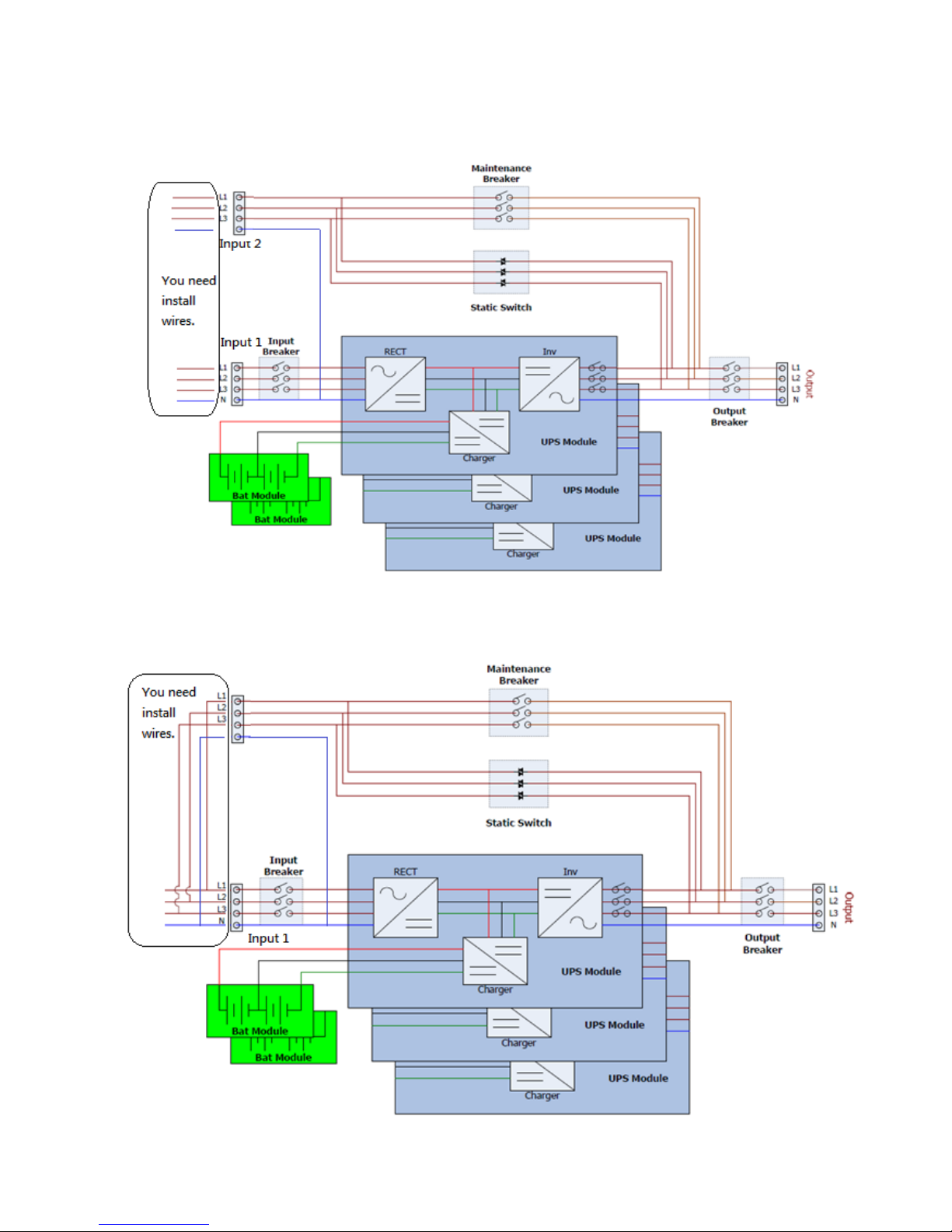
2 Operation & structure
Figure 2-1: Wiring diagram for dual inputs
Figure 2-2: Wiring diagram for single input
Page 7
4
3. Installation
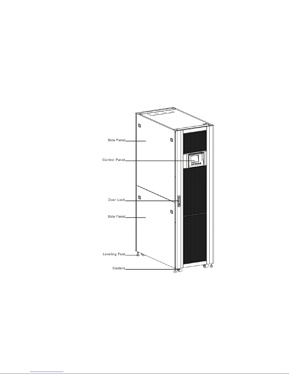
3.1 Mechanism and Exterior
In the front of the UPS, there are control interface (LCD Panel) and door lock. Inside the cabinet,
there are an STS Module, 1~8 Power Module slots and Battery modules.
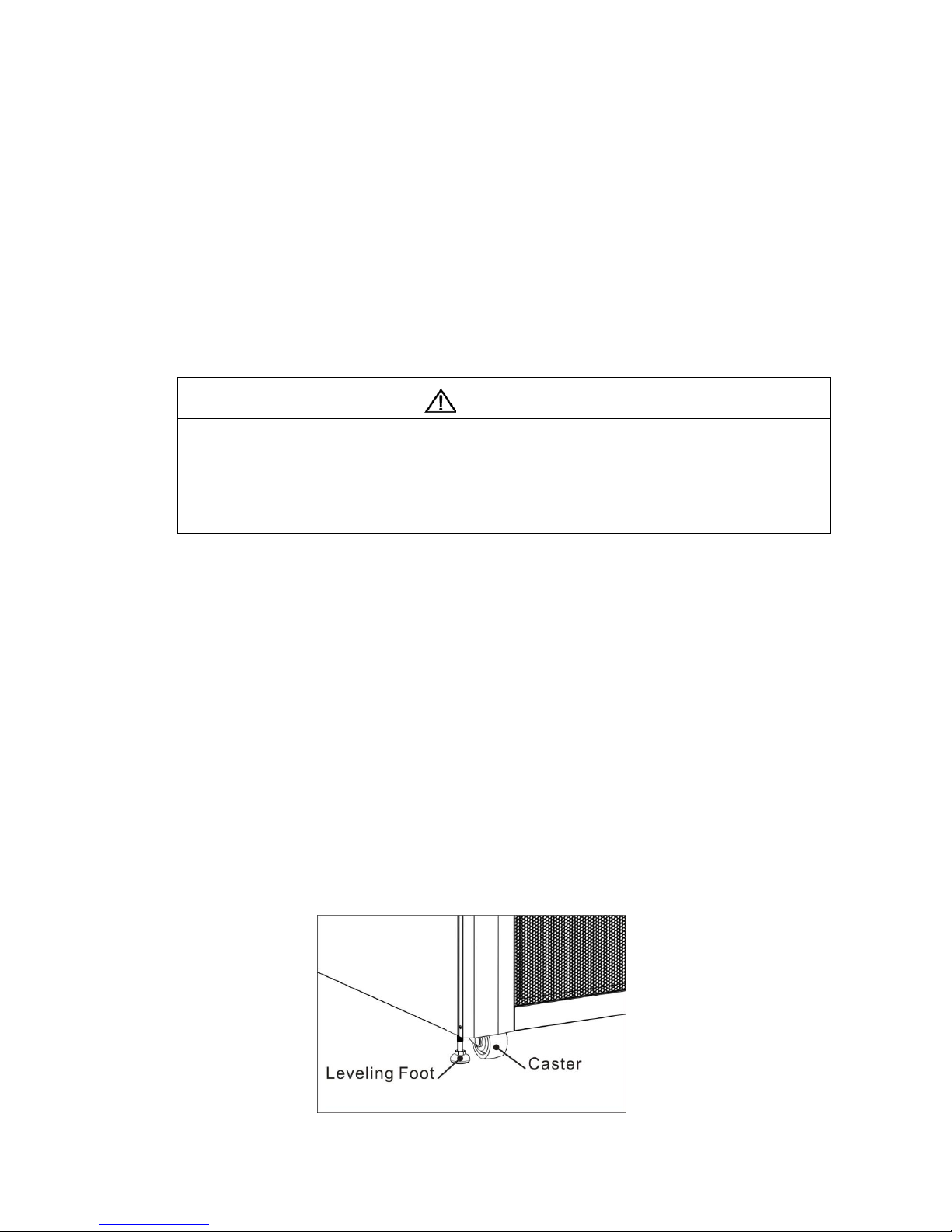
All wiring terminal blocks are allocated in the back of system. The side panels are lockable. The
casters at the bottom of the UPS cabinet can be used to move over short distances. There are four
leveling feet to fix and stabilize the UPS cabinet on the ground.
Figure 3-1:UPS Exterior
Page 8
5
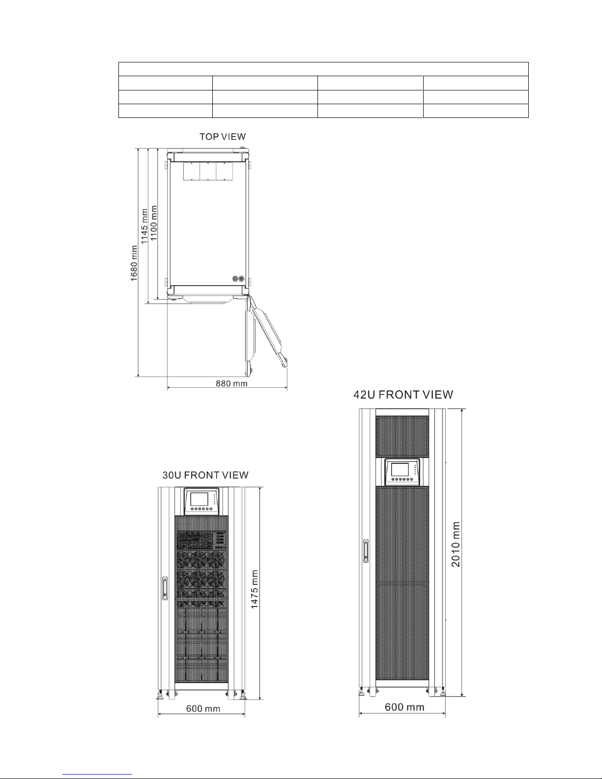
3.1.1 Mechanical Data
Dimensions
UPS cabinet
Width
Depth
Height
30~90Kw(30U)
600mm
1100m
1475mm
30~210Kw(42U)
600mm
1100m
2010mm
Figure 3-2: Dimensions
Page 9

6
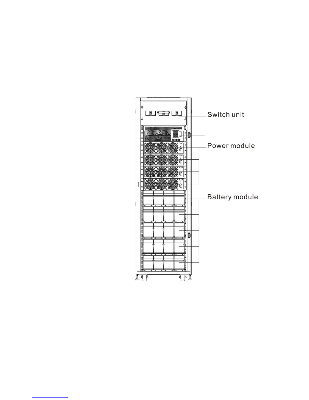
3.1.2 Other Views
‧Front View : Unlock and open the front door to see STS Module, Switch unit, Power Module and
Battery Module.
‧Rear View : Unlock and open the rear door to see Battery Breaker.
(Rear View) (Front View)
1. Switch unit
2. Bypass module
3. Power module
4. Battery module
5. Battery breaker
Figure 3-3: Front and Rear View
Page 10
7
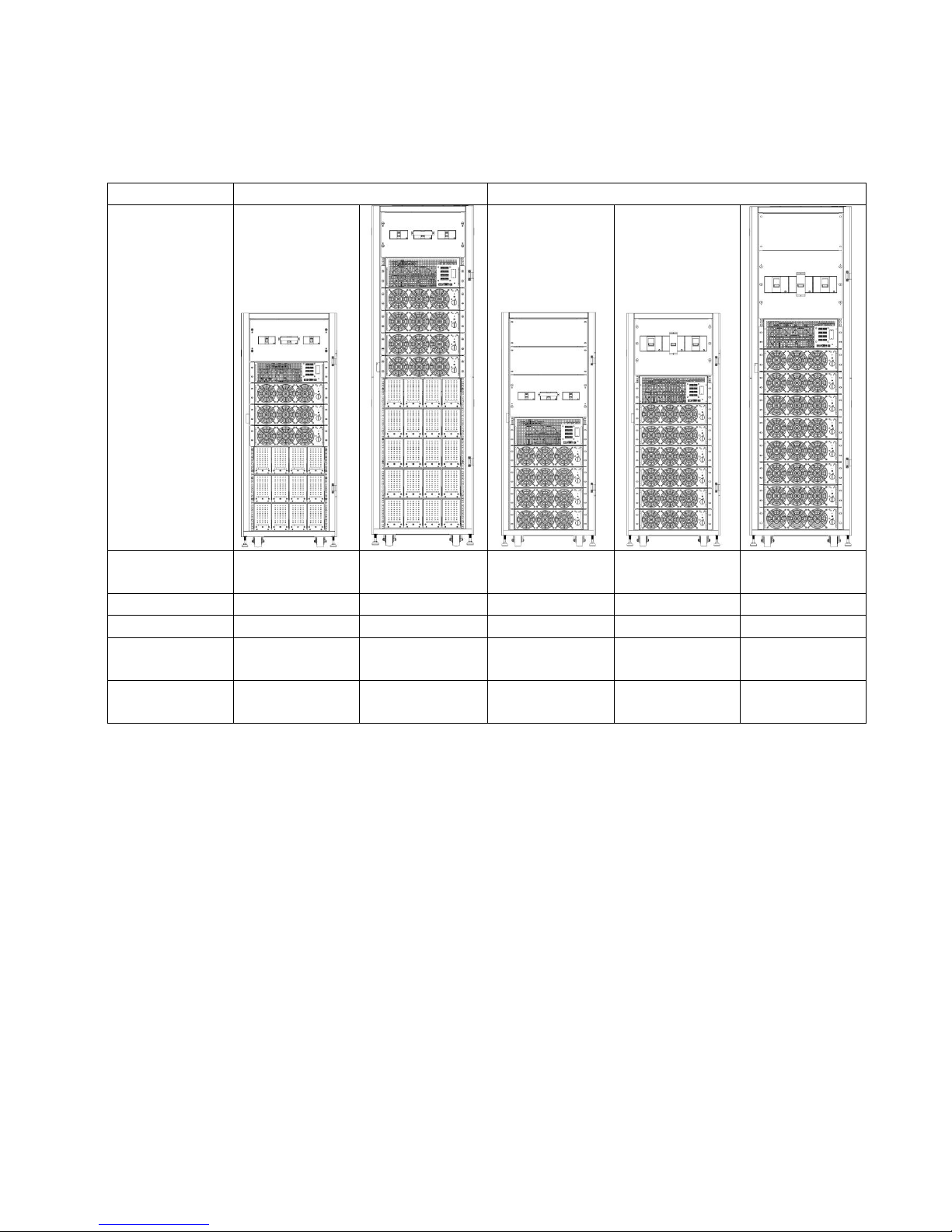
Configurations:
There are two basic configurations for different applications.
It’s required to have battery module for Standard Series.
Please consider the external battery space and wiring gauge for Extended Series.
Standard Series
Extended Series
Photo
Cabinet
Height
30U
42U
30U
30U
42U
Switch Unit
1 1 1 1 1
STS 1 1 1 1
1
Max. Power
Module
3 4 4 6 8
Battery
Module
12
20
N/A
N/A
N/A
Page 11
8
3.2 Internal Mechanisms
After opening the front door, you can see the Switch unit, Bypass module, Power module and
Battery module. After opening the back door, you can see the Battery Breaker and input/ output
wiring terminal block. Please refer to the following sections.
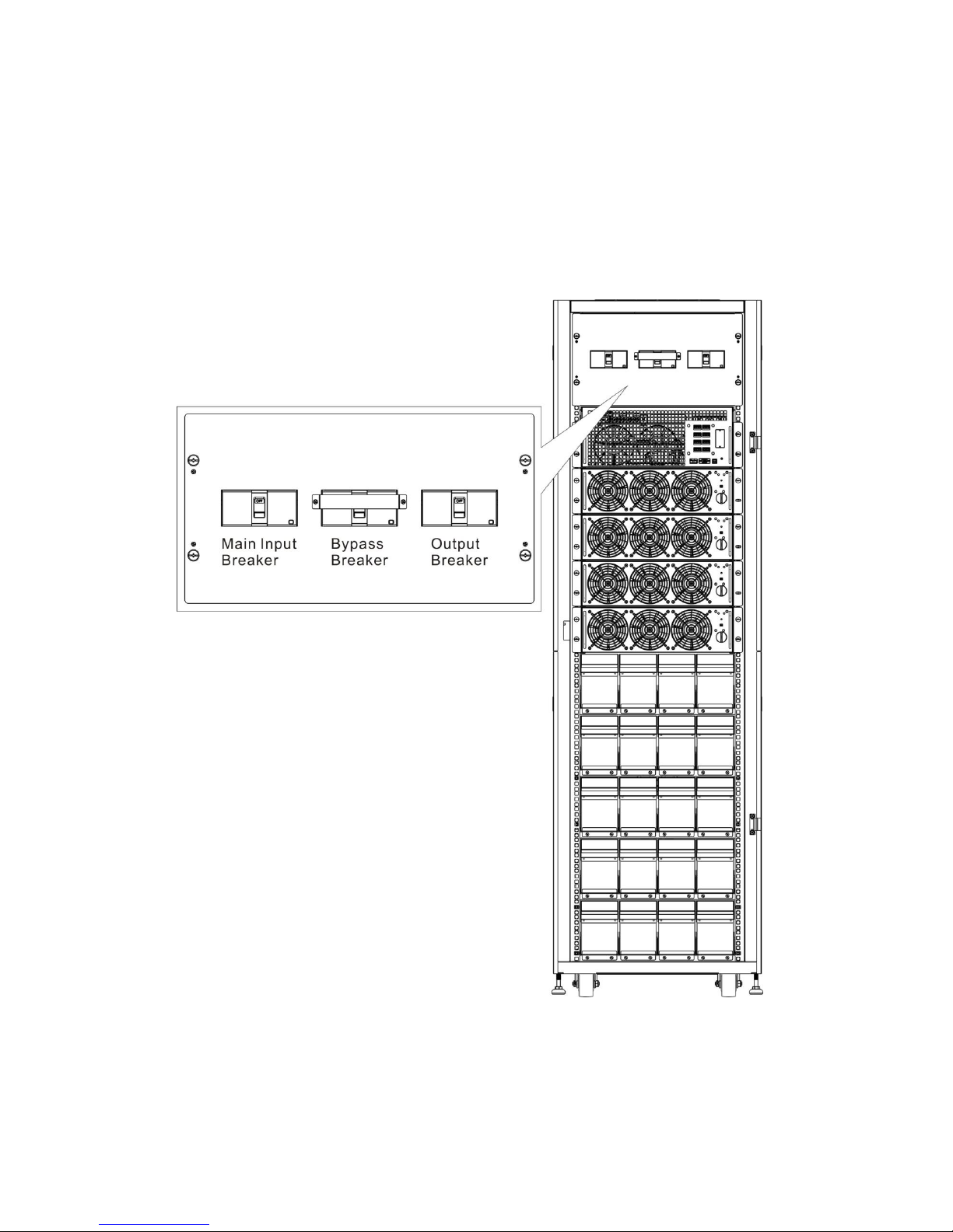
3.2.1 Input and Output Breakers
Open front and back door. The Input Breaker, Bypass Breaker and Output Breaker are located on
the front of the UPS. The Battery Breaker and input/ output wiring terminal block are at the back of
the UPS. See Figure 3-4.
Figure 3-4: Front View/Output, Bypass, and Main Input Breakers
Page 12
9
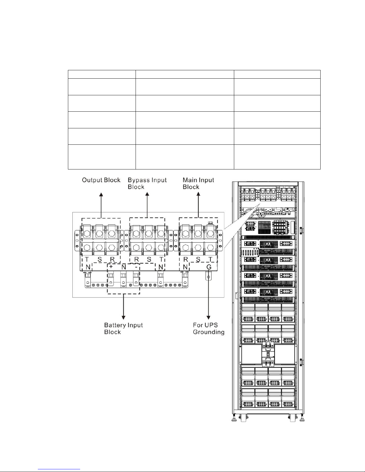
3.2.2 Wiring Terminal Block
Open the UPS’s back doors and you will see the wiring terminal block. For connection instructions,
please refer to Figure 3-5.
Item
Function
Description
Output Block
Connects the critical loads
Includes R, S, T and
Neutral terminals.
Bypass Input Block
Connects bypass AC source
Includes R, S, T and
Neutral terminals.
Main Input Block
Connects main AC source
Includes R, S, T and
Neutral terminals.
For UPS Grounding
For UPS grounding
Includes one grounding
terminal.
Battery Input Block
Connects an external battery
cabinet
Includes
Positive (+), Negative (-)
and Neutral (N) terminals.
Figure 3-5: Rear View & Wiring Terminal Block
Page 13
10
3.2.3 Modules
The STS & Control module and Power Module allow quick maintenance, replacement and
expansion. The module latches secure the modules in place.
‧STS & Control Module: It includes control, power, communication circuits, an internal Static
Transfer Switch and a fuse.
‧Power Module: Each power module capacity is 30kVA/ 30kW. It includes a power factor
correction rectifier, a battery charger, an inverter and control circuits.
‧Battery Module: It contains 4 sets of 10 pieces 12V/9Ah batteries inside of one battery
compartment.
Figure 3-6: Front View with Modules
STS & control module
Page 14

11
3.3 Control Panel & interface
The front access Graphic Display & Control interface brings all measured parameter, UPS & Battery
current states and Alarms. Through the interface, users can easily monitor status and configure
settings. For detailed information, please refer to the charter 4.
Figure 3-7: Control Panel
3.3.1 LED indications
LED
Color
Status
Definition
INPUT
Green
On
Input source is normal.
Flashing
Input source is abnormal.
Off
No input source
BYPASS
Green
On
Load on Bypass.
Flashing
Input source is abnormal.
Off
Bypass not operating.
INVERTER
Green
On
Load on inverters.
Off
Inverters not operating.
BATTERY
Yellow
On
Load on Battery.
Flashing
Low battery
Off
Battery converter is normal and battery is charging.
ALARM
Red
On
UPS fault.
Flashing
UPS alarm.
Off
Normal.
3.3.2 LCD Display
Graphic display and all measured parameters.
Page 15

12
3.3.3 Function Keys
Control Key
Description
Esc
Return to previous screen or cursor displacement. When screen is in
Main screen, it will enter setting menu by pressing ESC key.
Up(Left)
Key for menu page navigation or digit modification.
Down(Right)
Key for menu page navigation or digit modification.
Enter
Confirmation of commands, or cursor displacement.
Home
Return to Main screen.
Power
On/Off
Turn on UPS or Turn off UPS.
3.4 Installation and Wiring
3.4.1 Before Installation
Due to different installation environments, please read this user manual thoroughly before
installation and wiring. Only authorized engineers or service personnel can perform installation and
maintenance. If you want to install the UPS by yourself, installation must be under the supervision
of authorized engineers or service personnel.
If you use a forklift or other equipment to move the UPS, please make sure its load bearing is
sufficient.
3.4.2 Installation Environment
The UPS is designed for indoor use only. Do not install or place it in an outdoor area.
Make sure that transportation routes (e.g. corridor, door gate, elevator, etc) and installation
area can accommodate and bear the weight of the UPS, the external battery cabinet and
handling equipment.
Ensure that the installation area is big enough for maintenance and ventilation.
Keep the installation area’s temperature around 30°C and humidity within 90%. The highest
operating altitude is 2000 meters above sea level.
The UPS is intended for indoor installation and should be located in an environment with clean
air and with adequate ventilation to keep the ambient temperature within the specified
operating range. The UPS is air-cooled with the aid of internal fans. Cold air enters the UPS
through.
If necessary, install a system of room extractor fans to avoid room temperature build-up. Air
filters are necessary if the UPS is operated in a dusty environment.
Note: The UPS is suitable for mounting on concrete or other non-combustible surface only.
The UPS is air-cooled with the aid of internal fans. Cold air enters the UPS through the
ventilation grilles at the front of the cabinet and hot air is released through the grilles at the
back. Do not cover the ventilation openings.
Do not allow unauthorized personnel to enter the installation area. Assign specific personnel to
keep the UPS key.
Page 16
13
For safety concerns, we suggest that you shall:
1. Surroundings of the installation area with CO2 or dry powder fire extinguishers.
2. Install the UPS in an area where the walls, floors and ceilings were constructed by fireproof
materials.
It is recommended that you parallel the external battery cabinets to the UPS. The following
clearances are suggested:
1. Keep a clearance of 100cm from the top of the UPS for maintenance, wiring and ventilation.
2. Keep a clearance of 100cm from the back of the UPS and the external battery cabinets for
ventilation.
3. Keep a clearance of a 150cm from the front of the UPS and the external battery cabinets for
maintenance and ventilation.
3.4.3 Transportation
Warning
The UPS is fixed on the pallet with four balance supports. When removing them,
pay attention to the movement of the casters to avoid accidents.
The cabinet can be pushed forward or backward only. Pushing it sideward is not
allowed. When pushing the cabinet, take care
not to overturn it as the gravity center is high.
If you need to move the UPS over a long distance, please use appropriate equipment like a
forklift. Do not use the UPS casters to move the over a long distance.
After the UPS has been removed from the pallet to ground, we suggest that at least three
people move the UPS to the installation area. One person use hands to hold a lateral side of
the UPS, one person hold the other lateral side of the UPS with hands, and one person use
hands to push the UPS either from the front side or from the backside to move the unit to the
installation area and avoid tipping the UPS.
The casters are designed to move on level ground. Do not move the UPS on an uneven
surface. This might cause damage to the casters or tip the UPS which could damage the unit.
Ensure that the UPS weight is within the designated surface weight loading of any handling
equipment.
At the bottom of the UPS, there are four casters to help you to move the UPS to a designated
area. Before you move the UPS, please turn the four leveling feet counterclockwise to raise
them off the ground. This protects the leveling feet from damage when moving the UPS.
Please use sufficient manpower(at least six people) and equipment (e.g. forklift) to carefully
move the UPS from its pallet to ground. Please pay attention to the movement of the casters to
avoid accidents.
Figure 3-8: Leveling foot and caster
Page 17
14
3.4.4 Unpacking
After shipping the product to the user first check the packaging to determine intact, and then
open the package, check the equipment in good condition. If damaged, please immediately
notify the carrier.
3.4.4.1 System Packaging
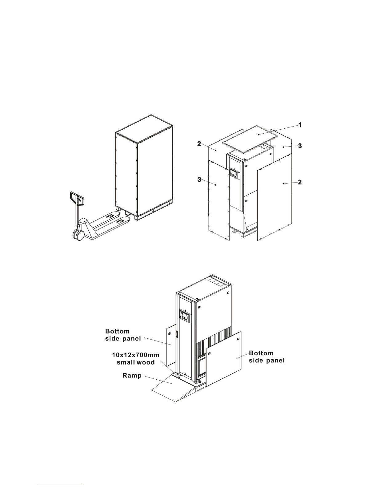
1. Use a forklift to move the product to installed area. Refer to Figure 3-9.
2. Please remove 5 boards in order (from 1 to 5) as shown in Figure 3-10.
Figure 3-9 Figure 3-10
3. Put a ramp in the front of the cabinet and insert small wood into groove. Then, remove two
side panels. Refer to Figure 3-11.
Figure 3-11
Page 18
15
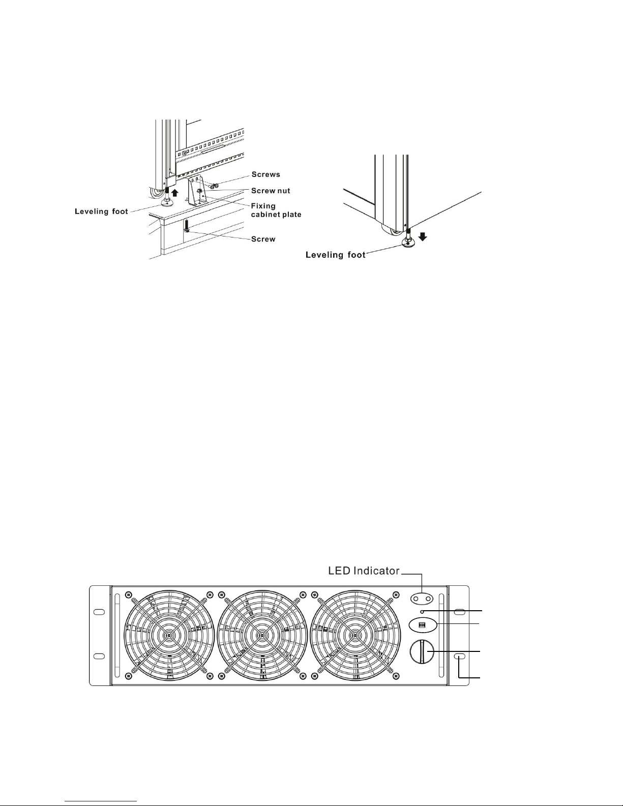
4. Remove 4 fixing cabinet plates and loosen leveling feet by rotating in counterclockwise.
Then, move the cabinet from the pallet.
5. To fix the cabinet in position, simply rotate leveling feet in clockwise.
Figure 3-12 Figure 3-13
3.4.5 Positioning
Leveling feet are provided at the bottom of the UPS cabinet to prevent the UPS from moving once
it has been placed to its final position. For optimal design life, the installed place must be:
easy connection
enough space to easily work on the UPS
sufficient air exchange to dispel heat produced by UPS
protection against atmospheric agents
protection against excessive humidity and high heat sources
protection against dust
compliance with the current fire prevention requirements
For VRLA (Valve Regulated Lead Acid) batteries the operating environment
temperature is kept between 20°C and 25°C. VRLA batteries are at maximum
efficiency in this temperature range
3.5 Modules
The hot-swappable Power Modules allow quick maintenance and expansion. A latch located on the
front of each module fixes and locks the module in its assigned slot. Each Power Module has an
LED indicator to show its operation status.
3.5.1 Power Module
Figure 3-14: Power module
Cold start button
DIP switch
Ready switch
Fixing hole
Page 19

16
The Power Module’s LED indicator shows its operation status. Please refer to the following table:
No.
LED indicator
Description
1
FAULT
Steady red LED indicates that the system is abnormal.
2
FAULT
Flashing red LED indicates that the system is in parallel
abnormal.
3
RUN
Flashing green LED indicates normal operation of the
host UPS.
4
RUN
Steady green LED indicates normal operation of the
slave UPS.
3.5.2 Install a Power Module
Follow below procedures to install the power module.
1. Use the DIP switch on the front panel of each Power module to set the module address.
The setting range is from 1 to 3. The module address should be exclusive. The setting
method is shown in Table 3-1.
Module address
MODULE
DIP SWITCH
Parallel board
0
POWER
SW1 and SW2 DIP
Parallel board is
located at the back of
UPS cabinet. The
appearance is shown
in figure 3-15.
1
POWER
2
POWER
3
POWER
4
POWER
5
POWER
6
POWER
7
POWER
Table 3-1 DIP switch setting method
Page 20

17
Figure 3-15 Parallel board
2. Place the ready switch on the front panel of the module to the “ ” position (i.e., in
unready state).
3. Insert one power module in the installation position and push it into the cabinet.
4. Secure the module to the cabinet through the fixing holes on both sides of the front
panel of the module.
5. Place the ready switch to the “ ” position (i.e., in ready state).
3.5.3 Remove a Power Module
Warning
Before removing any Power Module, make sure the remaining Power Modules can
support the critical loads.
1. Turn the ready switch to the “ ” position.
2. The Power Module LED indicator is off to indicate the Power Module discharged and
shut down completely.
3. Use a screwdriver to remove the four screws from fixing holes.
4. Two people pull out together and remove the Power Module from its slot.
3.5.4 STS Module
For detail settings, please refer to character 4.
Figure 3-16: STS module
Page 21

18
3.5.5 Remove the STS Module
Warning
1. Only qualified service personnel can perform the following procedures.
2. The STS Module has been pre-installed in the factory. Only remove the STS Module
when maintenance or replacement is necessary.
3. When the UPS is in Bypass Mode and its critical loads are connected, removing the
STS Module without turning off the Bypass Breaker could generate high voltage,
which may melt its connectors.
4. If the UPS is in Bypass Mode, cutting off the bypass AC source will terminate power
supply to the critical loads.
5. The STS Module is heavy (>30 kg). At least two people are required for handling.
Please follow the steps below to remove the STS Module.
1. Turn OFF the Bypass Breaker.
2. Use a Screwdriver to remove the four screws from the two sides of the STS Module.
3. Two people together pull out and remove the STS Module.
NOTE: Reverse the steps above to insert the STS module.
3.5.6 Battery Installation
Please follow below charts to install and connect wires to internal battery modules and external
battery cabinet.
Internal Battery Module Connection
Page 22

19
External Battery Cabinet Connection
After battery is completely installed, be sure to set up nominal battery voltage, battery capacity
and maximum charging current in LCD setting. Otherwise, if battery setting is different from real
installation, the UPS will keep warning. Please refer to section 4.2.6.3 and Table 5-17 for the
details.
3.6 Power Cable
Warning
Please follow the local wiring regulations. Follow environmental conditions and
refer to IEC60950-1.
Page 23

20
3.6.1 AC input and output maximum current and power cable configuration.
For standard model in 30U cabinet (battery inside)
Model
30KVA
60KVA
90KVA
Current (A)
57
114
171
Power cable (mm2)
10
35
70
Fixation torque force (lb-in)
20
20
20
For standard model in 42U cabinet (battery inside)
Model
30KVA
60KVA
90KVA
120KVA
Current (A)
57
114
171
228
Power cable (mm2)
10
35
70
95
Fixation torque force (lb-in)
20
20
20
20
For extended series in 30U & 42U cabinet
Model
30KVA
60KVA
90KVA
120KVA
150KVA
180KVA
210KVA
Current (A)
57
114
171
228
285
342
399
Power cable
(mm2)
10
35
70
95
150
240
300
Fixation torque
force (lb-in)
20
20
20
20
20
20
20
Notice: Installer has to consider the max. current and wiring gauge as possible for future
extension.
3.6.2 DC input maximum current and power cable configuration.
For standard series in 30U cabinet (battery inside)
Model
30KVA
60KVA
90KVA
Current (A)
100
200
300
Power cable (mm2)
25
95
150
Fixation torque force (lb-in)
20
20
20
Notice: 90KVA is required to set up external battery cabinet for standard model.
For standard series in 42U cabinet (battery inside)
Model
30KVA
60KVA
90KVA
120KVA
Current (A)
100
200
300
400
Power cable (mm2)
25
95
150
240
Fixation torque force (lb-in)
20
20
20
20
Notice: 120KVA is required to set up external battery cabinet for standard model.
For extended series in 42U cabinet
Model
30KVA
60KVA
90KVA
120KVA
150KVA
180KVA
210KVA
Current (A)
100
200
300
400
500
600
700
Power cable
(mm2)
25
95
150
240
120 x 2
150 x 2
240 x 2
Fixation torque
force (lb-in)
20
20
20
20
20
20
20
Page 24

21
4. Control Panel and Display Description
4.1 Introduction
This control panel and display description is located on the front door of the UPS. It is the USER
control and monitoring of all measured parameters, UPS and battery status and alarms. The
control panel and display description is divided into three functional areas: (1) LCD display, (2)
LED indications, (3) Control keys, (4) Audio Alarm, as shown in Figure 4-1.
Figure 4-1 Control panel parts
(1) LCD display: Graphic display and all measured parameters.
(2) LED indications. Refer to table 4-1.
(3) Control keys. Refer to table 4-2.
Page 25

22
Table 4-1: LED indications
LED
Color
Status
Definition
INPUT
Green
On
Input source is normal.
Flashing
Input source is abnormal.
Off
No input source
BYPASS
Green
On
Load on Bypass.
Flashing
Input source is abnormal.
Off
Bypass not operating.
INVERTER
Green
On
Load on inverters.
Off
Inverters not operating.
BATTERY
Yellow
On
Load on Battery.
Flashing
Low battery
Off
Battery converter is normal and battery
is charging.
ALARM
Red
On
UPS fault.
Flashing
UPS alarm.
Off
Normal.
Table 4-2: Function key table
Control Key
Description
Esc
Return to previous screen or cursor displacement. When
screen is in Main screen, it will enter setting menu by
pressing ESC key.
Up(Left)
Key for menu page navigation, or digit modification.
Down(Right)
Key for menu page navigation, or digit modification.
Enter
Confirmation of commands, or cursor displacement.
Home
Return to Main screen.
Power On/Off
Turn on UPS or Turn off UPS. (hold 2-Sec)
(4) Audible Alarm: Table 4-3
Audio Type
Description
Power on/off
Buzzer sounds two seconds.
Battery mode
Buzzer sounds every 2 seconds.
Low battery
Buzzer sounds every half seconds.
UPS alarm
Buzzer sounds every 1 second.
UPS fault
Buzzer continuously sounding.
Page 26

23
4.2 Screen Description
4.2.1 Start Screen
Upon UPS start, the UPS executes self-test. The initial screen displays and remains approximately
5 seconds as shown in Figure 4-2.
Figure 4-2 Initial screen
4.2.2 Main Screen
After initialization, the main screen will display as Figure 4-3. Main screen is divided into five parts.
(1) UPS Mode: Current Operation Mode.
(2) UPS Flow Chart: Current flow chart and measurement data.
(3) Menu: Press ESC button to enter Menu screen.
(4) UPS model name with power rating.
(5) Date and Time.
Figure 4-3 Main screen
Page 27

24
4.2.3 Menu Screen
Use UP and DOWN buttons to choose between different menus, and Press ENTER to enter into the
sub screen, as shown in Figure 4-4 and 4-5.
Figure 4-4 Menu tree
Figure 4-5 Menu screen
4.2.4 Control Screen
Use UP and DOWN buttons to choose CONTROL option, and press ENTER button to enter into the
submenu, as shown in Figure 4-6 and 4-7.
Figure 4-6 Control menu
Page 28

25
Figure 4-7 Control screen
Use LEFT and RIGHT buttons to choose YES or NO. Choose YES and press ENTER button to
confirm command or choose NO to cancel command, as shown in Figure 4-8.
Figure 4-8 Yes or No screen
4.2.5 Measurement Screen
Use UP and DOWN buttons to choose MEASUREMENT option. Choose module ID number to
measure Input, Output, Bypass, Load, and Battery of every module, as shown in Figure 4-9, 4-10
and Table 4-4.
Figure 4-9 Measurement menu
Page 29

26
Figure 4-10 Measurement screen
Table 4-4
Menu
Item
Explanation
Input
L-N Voltage (V)
Input phase voltage (L1, L2, L3). Units 0.1V.
Frequency (Hz)
Input Frequency (L1, L2, L3). Units 0.1Hz.
Output
L-N Voltage (V)
Output phase voltage (L1, L2, L3). Units 0.1V.
L-N Current (A)
Output phase current (L1, L2, L3). Units 0.1A.
Frequency (Hz)
Output Frequency (L1, L2, L3). Units 0.1Hz.
Power Factor
Output Power Factor (L1, L2, L3).
Bypass
L-N Voltage (V)
Bypass phase voltage (L1, L2, L3). Units 0.1V.
Frequency (Hz)
Bypass Frequency (L1, L2, L3). Units 0.1Hz.
Power Factor
Bypass Power Factor (L1, L2, L3).
Load
Sout (KVA)
Apparent power. Units 0.1KVA.
Pout (KW)
Active power. Units 0.1KW.
Load Level (%)
The percentage of the UPS rating load. Units 1%.
Battery
Positive Voltage (V)
Battery Positive Voltage. Units 0.1V.
Negative Voltage
(V)
Battery Negative Voltage. Units 0.1V.
Positive Current (A)
Battery Positive Current. Units 0.1A.
Negative Current
(A)
Battery Negative Current. Units 0.1A.
Remain Time (Sec)
Battery run time remaining. Units 1sec.
Capacity (%)
The percentage of the capacity of the battery.
Units 1%.
Test Result
Battery test result
Charging Status
Battery charging status
Page 30

27
4.2.6 Setup Screen
Use UP and DOWN buttons to choose SETUP options. It’s required to enter password to access
General, SYSTEM and BATTERY sub-menus, as shown in Figure 4-11, 4-12 and 4-13.
Figure 4-11 Setup menu
It’s required to enter 4-digit password to enter SETUP menu. If incorrect password is entered, the
LCD screen will ask for retry.
Figure 4-12 Enter password screen
Figure 4-13 Setup screen
Page 31

28
Table 4-5 All setting items in Setup Menu
UPS operation
mode
Setting item
Standby
Mode
Bypass
Mode
Line
Mode
Battery
Mode
Battery
Test Mode
Fault
Mode
Converter
Mode
ECO
Mode
Model Name
Y Y Y Y Y Y Y Y Language
Y Y Y Y Y Y Y Y TIME
Y Y Y Y Y Y Y
Y
Change Password
Y Y Y Y Y Y Y Y Baud Rate
Y Y Y Y Y Y Y
Y
Audible Alarm
Y Y Y Y Y Y Y Y Factory Reset
Y
EEPROM Reset
Y
EPO Function
Y Save Setting
Y Y
Output Voltage
Y Y
Bypass Voltage
Range
Y Y Y Y Y Y Y
Y
Bypass Frequency
Range
Y Y
Converter Mode
Y ECO Mode
Y Y Y Y Bypass Mode
Y Y Auto-Restart
Y Y Y Y Y Y Y Y Cold Start
Y Y Y Y Y Y Y
Y
Battery Mode
Delay Time
Y Y Y Y Y
Y
System Shutdown
Time
Y Y Y Y Y Y Y
Y
System Restore
Time
Y Y Y Y Y Y Y
Y
Redundancy
Y Y Y Y Y Y Y
Y
Nominal Battery
Voltage
Y Y
Battery Capacity
in Ah
Y Y Y Y Y
Y
Maximum
Charging Current
Y Y
Battery
Low/Shutdown
Setting
Y Y Y Y Y
Y
Page 32

29
Periodic Battery
Test
Y Y Y Y Y Y Y
Y
Battery Test
Interval
Y Y Y Y Y Y Y
Y
Stop by Time
Y Y Y Y Y Y
Y
Stop by Battery
Voltage
Y Y Y Y Y Y
Y
Stop by Battery
Capacity
Y Y Y Y Y Y
Y
Battery Age Alert
Y Y Y Y Y Y Y Y Pre-Alarm
Y Y Y Y Y Y Y Y UPS Parallel
Y Y
Independent
Battery
Y Y
Y means that this setting item can be set in this operation mode.
4.2.6.1 Setup-General Screen
Use UP and DOWN buttons to choose between different sub-menus, and press ENTER button to
enter into the GENERAL setting screen, as shown in Figure 4-14. General setting can be set in any
operating mode and Setup-General setting list is shown in table 4-6.
Figure 4-14 Setup-General screen
Use LEFT and RIGHT buttons to choose YES or NO. Choose YES and press ENTER button to
confirm the setting change or choose NO to cancel the setting, as shown in Figure 4-15.
Page 33

30
Figure 4-15 SETUP YES or NO screen
Table 4-6
Setting Item
Sub Item
Explanation
Model Name
Set UPS Name(xxxxxxxxxx)
Language
--
Provides 3 optional LCD languages (English,
Traditional Chinese and Simplified Chinese )
TIME
Adjust Time
Set current date and time (yyyy / mm / dd
hour : min : sec)
System Installed Date
Set system installed date (yyyy / mm / dd)
System Last Maintain
Date
Set system latest maintenance date (yyyy /
mm / dd)
Battery Installed Date
Set battery installed date (yyyy / mm / dd)
Battery Last Maintain
Date
Set battery latest maintenance date (yyyy /
mm / dd)
Change Password
--
Set New Password.
Baud Rate
--
Set COM Port0 Baud Rate(2400, 4800,
9600)
Set COM Port1 Baud Rate(2400, 4800,
9600)
Audible Alarm
--
Set Audible Alarm “Disable” or “Enable”
Factory Reset
--
Restore to factory default setting
EEPROM Reset
--
Set EEPROM default
EPO Function
--
Set EPO “Normal Close Active” or “Normal
Open Active”
Save Setting
--
Save EEPROM
Page 34

31
4.2.6.2 Setup-System Screen
Use UP and DOWN buttons to browse different menus and press ENTER button to enter into the
SYSTEM setting screen, as shown in Figure 4-16. System setting can be set only when UPS is
operated in certain mode. Please check setting item availability table 4-5 for the details. If it’s not
set up under specific mode, the warning screen will appear. Refer to figure 4-17 and Setup-System
setting list is shown in table 4-7.
Figure 4-16 Setup-System screen
Figure 4-17 Warning screen
Page 35

32
Table 4-7
Setting Item
Sub Item
Explanation
Output Voltage
--
Set output voltage (220Vac, 230Vac,
240Vac)
BYPASS SETTING
Bypass Voltage
Range
Set bypass voltage range: upper limit
(+10%, +15%, +20%) and lower limit
(-10%, -20%, -30%)
Bypass Frequency
Range
Set bypass Frequency range: upper limit
(+1Hz, +2Hz, +4Hz) and lower limit
(-1Hz, -2Hz, -4Hz)
Converter Mode
--
Set converter mode “Disable” or ”Enable”
ECO Mode
--
Set ECO mode “Disable” or ”Enable”
Bypass Mode
--
Set bypass mode “Disable” or ”Enable”
Auto-Restart
--
Set auto-restart “Disable” or ”Enable”.
After “Enable” is set up, once UPS
shutdown occurs due to low battery and
then utility restores, the UPS will return to
line mode.
Cold Start
--
Set cold start “Disable” or ”Enable”.
After “Enable” is set, the UPS can be
turned on without utility connection by
pressing Battery Start Button. Refer to
cold start operation for the details.
Battery Mode Delay
Time
--
Set system shutdown delay time in
battery mode (0~9990sec)
System Shutdown
Time
--
Set system shutdown time (0.2~99min)
System Restore
Time
--
Set system restore time (0~9999min)
Redundancy
--
Set total power and redundancy
Page 36

33
Cold Start Operation
Step 1: Press “Cold Start” button as shown in below chart.
Cold Start Button
Step 2: After pressing Cold Start Button, UPS will enter Standby mode. Refer to below chart for
LCD display.
Step 3: Before UPS enters shutdown mode, please press “Power On/Off” button for 2 second
immediately as shown in below chart.
Page 37

34
Step 4: Then, UPS will enter Battery Mode as shown below chart. Cold start procedure is
complete.
4.2.6.3 Setup-Battery Screen
Use UP and DOWN buttons to switch different sub-menus. Press ENTER button to enter into the
BATTERY setting screen, as shown in Figure 4-18. Battery setting can be set only when UPS is
operated in standby mode. If it’s not in standby mode, the warning screen will appear as shown in
Figure 4-17. See Battery-System setting list in table 4-8.
Figure 4-18 Setup-Battery Screen
Page 38

35
Table 4-8
Setting Item
Sub Item
Explanation
Nominal Battery Voltage
--
Set battery nominal voltage(16x12V,
18x12V, 20x12V)
Battery Capacity in Ah
--
Set battery capacity. (0~999)
Maximum Charging
Current
--
Set battery maximum charging current
(1~128A)
BATTERY
LOW/SHUTDOWN
SETTING
Battery Low
Voltage
Set battery low voltage
(10.5~11.5V)x(battery Number)
Battery Low
Capacity
Set battery low capacity (20~50%)
Battery Shutdown
Voltage
Set battery voltage point for system
shutdown in battery mode
(10.0~11V) x (battery Number)
Battery Shutdown
Capacity
Set battery level for system shutdown in
battery mode (10~50%)
BATTERY TEST
Periodic Battery
Test
Set periodic battery test “Disable”
or ”Enable”
Battery Test
Interval
Set battery test interval (7~99 Days)
Stop by Time
Set testing time for battery test
(10~1000sec)
Stop by Battery
Voltage
Set stop battery voltage in battery test
(11~12V) x (battery Number)
Stop by Battery
Capacity
Set battery capacity to stop
battery-testing. (20~50%)
Battery Age Alert
Battery Age Alert
(Months)
Set battery age for replacement.
(12~60Months)
4.2.6.4 Pre-Alarm Screen
Use UP and DOWN buttons to switch different sub-menus. Press ENTER button to enter into the
Pre-Alarm setting screen, as shown in Figure 4-19. Pre-Alarm setting can be set in any operation
mode. See Setup-Pre-Alarm setting list in table 4-9.
Figure 4-19 Setup-Pre-Alarm screen
Page 39

36
Table 4-9
Setting Item
Sub Item
Explanation
Line Voltage Range
--
Set line voltage range: upper limit (+5%,
+10%, +15%, +20%) and lower limit
(-5%, -10%, -15%, -20%)
Line Frequency Range
--
Set line frequency range: upper limit
(+1Hz, +2Hz, +3Hz, +4Hz) and lower
limit (-1Hz, -2Hz, -3Hz, -4Hz)
Load
Overload
Set UPS Overload percentage
(40~100%)
Load Unbalance
Set UPS output load unbalance
percentage (20~100%)
4.2.6.5 Parallel Screen
Use UP and DOWN buttons to switch different sub-menus. Press ENTER button to enter into the
Parallel setting screen, as shown in Figure 4-20. Parallel setting can be set only when UPS is
operated in standby or bypass mode. If it’s not in standby or bypass mode to set up, the warning
screen will appear as shown in Figure 4-17. See Setup-Parallel setting list in table 4-10.
Figure 4-20 Setup-Parallel screen
Table 4-10
Setting Item
Sub Item
Explanation
UPS Parallel
--
Set UPS parallel “Disable” or ”Enable”
Independent Battery
--
Set Independent Battery “Disable”
or ”Enable”
Page 40

37
4.2.7 Information Screen
In this Screen you can check the UPS configuration of the unit, and INFORMATION divided into
Identification, System and Battery, as shown in Figure 4-21, 4-22, 4-23, 4-24 and 4-25.
Figure 4-21 Information menu
Figure 4-22 Information screen
Figure 4-23 Information-Identification screen
Page 41

38
Figure 4-24 Information-System screen
Figure 4-25 Information-Battery screen
4.2.8 Events Screen
When event occurs, you will see flashed warning text in the Main Screen as shown in Figure 4-26.
Besides, you also can enter the EVENTS Menu to check the latest event lists and history events as
shown in Figure 4-27 and 4-28.
Figure 4-26 Alarm warning screen
Figure 4-27 Events menu
Page 42

39
Figure 4-28 Events screen
4.2.8.1 Current Events
When event occurs, it displays Module ID and alarm code in Current Events screen. It can save up
to 50 events in current events. Only 4 events can list in one page. Therefore, if it exceeds more
than four, you have to press UP or DOWN button to read other event as shown in Figure 4-29.
Figure 4-29 Current Events screen
4.2.8.2 History Events
It saved detailed information in history events. When warning occurs, it will display alarm code,
alarm time and Module ID. When fault event occurs, it will display alarm code, alarm time, Module
ID and data 1~2. Refer to Figure 4-30 for display screen.
Page 43

40
Figure 4-30 History Events screen
4.2.8.3 Reset All Events
It’s required to enter 4-digit password to enter Reset All Events screen as shown in Figure 4-31.
Then, use LEFT and RIGHT buttons to choose YES or NO. Choose YES and press ENTER button to
reset all events or choose NO to cancel this action as shown in Figure 4-32.
Figure 4-31 Reset All Events screen
Page 44

41
Figure 4-32 Reset All Events screen
4.3 Alarm List
In Table 4-11, it provides the complete list of UPS alarm messages.
Table 4-11
Representation in display LCD
Explanation
Fault! Bus Over Voltage
DC bus voltage is too high
Fault! Bus Under Voltage
DC bus voltage is too low
Fault! Bus Voltage Unbalance
DC bus voltage is not balanced
Fault! Bus Short
DC bus is short
Fault! Bus Soft Start Time Out
The rectifiers could not start due to low
DC bus voltage within specified duration
Fault! Inverter Soft Start Time Out
Inverter bus voltage cannot reach desired
voltage within specified duration
Fault! Inverter Voltage Over
Inverter Voltage over (Peak Value)
Fault! Inverter Voltage High
Inverter Voltage is too high
Fault! Inverter Voltage Low
Inverter Voltage is too Low
Fault! R Inverter Voltage Short
R phase inverter Output is shorted
Fault! S Inverter Voltage Short
S phase inverter Output is shorted
Fault! T Inverter Voltage Short
T phase inverter Output is shorted
Fault! RS Inverter Voltage Short
R-S inverter Output is shorted
Fault! ST Inverter Voltage Short
S-T inverter Output is shorted
Fault! TR Inverter Voltage Short
T-R inverter Output is shorted
Fault! Inverter R Negative Power
R phase inverter Output Negative Power
over range
Fault! Inverter S Negative Power
S phase inverter Output Negative Power
over range
Page 45

42
Fault! Inverter T Negative Power
T phase inverter Output Negative Power
over range
Fault! Over Load Fault
Heavy overload causes UPS fault.
Fault! Battery Fault
Battery reverse
Fault! Over Temperature
Make sure adequate space is allowed for
air vents and the fan is working
Fault! CAN Fault
CAN communication fault
Fault! TRIG0 Fault
Synchronized trigger signal fault
Fault! Relay Fault
Inverter relay fault
Fault! Line SCR Fail
Line SCR short circuit fault
Fault! EEPROM Fault
EEPROM operation error
Fault! Parallel Cable Loosen Fault
As stated.
Fault! DSP MCU Stop Communicate
As stated.
Fault! Bypass Temperature Fault
As stated
Fault! Bypass SCR Fault
As stated.
Line Fail
Utility lost or abnormal
Line Restore
Utility recovered to normal
Warning! EPO Active
Check the EPO connector
Warning! Over Load Fail
The load devices are demanding more
power than the UPS can supply. Line
mode will transfer to Bypass mode.
Warning! Communicate CAN Fail
CAN communication error
Warning! Over Load
In Line mode, the load devices are
demanding more power than the UPS can
supply.
Warning! Battery Open
Battery not connected
Warning! Battery voltage High
Battery voltage is too High
Warning! Module Un-Lock
As stated.
Warning! Turn On Abnormal
As stated.
Warning! Charge Fail
As stated.
Warning! EEPROM Fail
EEPROM operation error
Warning! Fan Lock
As stated.
Warning! Line Phase Error
As stated.
Warning! Bypass Phase Error
As stated.
Warning! N Loss
Neutral loss
Warning! Internal Initial Fail
As stated.
Warning! Comm Syn Signal Fail
Communicate Synchronization Signal Fail
Warning! Comm TRIG0 Fail
Communicate Trigger signal fault
Warning! Redundancy Set Fail
As stated.
Warning! Parallel Sys Config Wrong
Parallel System Configure error
Page 46

43
Warning! Maintenance Bypass
Enter maintenance
Warning! Battery Age Alert
Battery Life expiration
Warning! Parallel Rack Cable Loosen
As stated.
Warning! Parallel Rack Config Wrong
Parallel Rack Configure error
Pre-Alarm! Line Voltage Fail
Line voltage over range
Pre-Alarm! Line Voltage Normal
Line voltage recovered to normal
Pre-Alarm! Line Frequency Unstable
Line frequency over range
Pre-Alarm! Line Frequency Normal
Line frequency recovered to normal
Pre-Alarm! Over Load
Output Load over range
Pre-Alarm! Load Normal
Output Load recovered to normal
Pre-Alarm! Load Unbalance
Output Load unbalance
Page 47

44
5. Interface and Communication
As shown in figure 5-1, the Static Transfer Switch (STS) Module includes dry contact Port (X1~X8),
and communication port (RS232 Port, USB port, SNMP Card Port) on the front panel.
Figure 5-1 Dry contact ports and communication ports
Dry Contact
No.
Function
X1
Remote EPO input port
X2
Reserve for system use
X3
BCB Port (Battery Circuit Breaker) – reserved
function
X4
Maintenance Bypass Switch State Port
X5
Internal Output Switch State Port – reserved
function – reserved function
X6
Battery Cabinet Temperature Detection
Port – reserved function
X7
Bypass back feed Control Port – reserved
function
X8
Battery breaker Control Port – reserved
function
5.1 Remote EPO Input Port
The UPS has an Emergency Power off (EPO) Function that can be operated by a remote contact
provide by user. Users can set the logic (N.C or N.O) of this EPO Function through LCD panel.
X1 is the remote EPO input port. The port is shown in Figure 5-2 and described in Table 5-1.
Figure 5-2 Remote EPO input port
Page 48

45
Table 5-1 Description of remote EPO port
EPO Logic Setting
Position
Description
N.C
X1.1 & X1.2
EPO activated when Opened X1.1 & X1.2
N.O
X1.1 & X1.2
EPO activated when Shorted X1.1 & X1.2
If EPO Logic setting is Normal Closed (N.C), EPO is triggered when pins 1 and 2 of X1 are opened.
Otherwise, EPO Logic setting is Normal Opened (N.O). EPO is triggered when pins 1 and 2 of X1
are opened.
Note:
1. EPO action shuts down the rectifiers, inverters and static transfer switch. But it does not
internally disconnect the input power supply.
2. The default setting of the EPO function logic is Normal Opened (N.O).
5.2 BCB Port
This function is reserved.
Figure 5-3 BCB port
Table 5-2 Description of BCB port
Name
Position
Description
BCB CONNECTED Pin1
X3.1
Reserved
BCB CONNECTED Pin 2
X3.2
Reserved
BCB STATUS Pin 3
X3.3
Reserved
BCB STATUS Pin 4
X3.4
Reserved
5.3 Maintenance Bypass Switch State Port
X4 is the maintenance bypass switch and External maintenance bypass switch state port. The port
is shown in Figure 5-4 and described in Table 5-3. (This function is reserved)
Page 49

46
Figure 5-4 Maintenance Bypass Switch State port
Table 5-3 Description of Maintenance Bypass Switch State port
Name
Position
Description
Maintain Bypass Pin1
X4.1
Maintenance bypass switch state
Maintain Bypass Pin 2
X4.2
Maintenance bypass switch state
Ext.Maintain Bypass Pin 3
X4.3
Ext.Maintenance bypass switch state
Ext.Maintain Bypass Pin 4
X4.4
Ext.Maintenance bypass switch state
5.4 Internal Output Switch State Port
X5 is the internal output switch state port. The port is shown in Figure 5-5 and described in Table
5-4. (This function is reserved)
Figure 5-5 Internal Output Switch State Port
Table 5-4 Description of Internal Output Switch State Port
Name
Position
Description
Internal Output Pin1
X5.1
Internal Output switch state (Reserved)
Internal Output Pin 2
X5.2
Internal Output switch state (Reserved)
5.5 Battery Cabinet Temperature Detection Port
The UPS has battery cabinet temperature detection function. UPS can through the external battery
cabinet temperature detection board to receive battery cabinet temperature. Communication
between the Ups and Battery temperature detection board was by I2C communication protocol. X6
is the battery cabinet temperature detection port. The port is shown in Figure 5-6 and described in
Table 5-5.
Page 50

47
Figure 5-6 Battery Cabinet Temperature Detection Port
Table 5-5 Description of Battery Cabinet Temperature Detection Port
Name
Position
Description
SCL
X6.1
I²C communication SCL Signal
SDA
X6.2
I²C communication SDA Signal
+3.0V
X6.3
3V
Power GND
X6.4
GND
5.6 Bypass back feed Control Port
This function is reserved.
Figure 5-7 Bypass back feed Control Port
Table 5-6 Description of Bypass back feed Control Port
Name
Position
Description
Pin1
X7.1
Reserved
Pin 2
X7.2
Reserved
5.7 Battery breaker Control Port
This function is reserved.
Page 51

48
Figure 5-8 Battery breaker Control Port
Table 5-7 Description of Battery breaker Control Port
Name
Position
Description
Pin1
X8.1
Reserved
Pin 2
X8.2
Reserved
5.8 Other Communication Interface
The RS232 port and USB Port can use in UPS commissioning and service or monitor the Ups
information by Monitoring Software .
This UPS has facility of internally fitted SNMP Card options.
Page 52

49
6. Service
This chapter introduces the UPS service, including the service procedures of the power module,
STS & control module, battery module and the replacement of air filter.
6.1
Replacement Procedures Of Power Module, STS & Control Module And
Battery Module
6.1.1 Notes
1. Only the customer service engineers shall service the power modules, bypass module and
battery modules.
2. Remove the power modules, bypass module and battery modules from top to bottom, so as to
prevent cabinet toppling due to high centre of gravity.
3. To ensure safety, before servicing the power modules and bypass module, be sure to use a
multimeter to verify that the DC bus capacitor voltage is lower than 60Vdc, and that the
voltages between the earth and the components you are going to work on are under dangerous
voltage values, that is, lower than 60Vdc or 42.4Vac peak value.
4. The static transfer switch module is NOT hot pluggable. It should be replaced only when
the UPS is in maintenance bypass mode or completely powered off.
5. The power modules and bypass module should be serviced five minutes and installed in the
cabinet again 10 minutes after they are removed.
6.1.2 Power Module Replacement Procedures
Confirm UPS is in normal mode and bypass function/source is available.
1. Enter to “menu” control Turn To Bypass YES on the operator control and display panel
for manually turn off the inverters. Then, the UPS transfers to bypass mode.
2. Turn ready switch to “ ” position on replaceable power module.
3. Two minutes later, remove the fixing screws on both sides of the front panel of the module and
pull the module out from the cabinet.
Note: The module will be blocked by a metal safe locker on the left side of the module when the
module is pulled out halfway from the cabinet. At this point, you must press the metal safe locker
before you continue to pulling the module out.
4. After servicing the module, confirm that the DIP switch of the module is set correctly and the
ready switch is in unready state “ ”.
5. Push the module into the cabinet and tighten the screws on both sides. If it’s more than one
power module to re-install, please wait 10-second duration before installing another module.
6. Wait for two seconds before turning ready switch of the module to “ ” position, it will be added
into the system automatically and begin to work few seconds later.
7. Press manual control system turn on YES on the operator control and display panel for
Page 53

50
two seconds to manually turn on the inverter mode.
6.1.3 STS & Control Module Service Procedures
The static transfer switch module is NOT hot pluggable.
Confirm the UPS is in normal mode and bypass function is available.
1. Press menu control Turn To Bypass YES on the operator control and display panel for
manually turn off the inverters, and the UPS transfers to bypass mode.
2. Turn on main switch and off maintenance bypass switch.
3. Two minutes later, remove the fixing screws on both sides of the front panel of the module and
pull the module out from the cabinet.
Note: The module will be blocked by a metal safe locker on the left side of the module when the
module is pulled out of the cabinet halfway. At this point, you must press the metal safe locker
before you continue to pulling the module out. Please refer to below illustration.
4. After servicing the module, push the module into the cabinet and tighten the screws on both
sides.
5. Turn on maintenance bypass switch and off main switch.
6. Wait for two seconds. Press menu control system turn on YES on the operator control
and display panel for two seconds to manually turn on the inverter mode.
6.1.4 Battery Module replacement Procedures
1. Disconnect each input connector of the battery module.
2. Remove the fixing screws on both sides of the front panel of the module, and pull out the
battery module.
3. Push the new battery module into cabinet and fixing screws on both sides of the front panel.
4. Re-connect each input connector of the battery module.
Page 54

51
6.2 Replacement Procedures Of Air Filter
As shown below figure, the UPS provides four air filters on the back of the front door. Each filter is
fixed by a fixing bar on both sides.
The air filter replacement procedures are as follows:
1. Open the front door of the UPS to reveal the air filters on the back of the door.
2. Remove a fixing bar on either side of the air filter.
3. Remove the air filter, and insert a clean one.
4. Replace the fixing bar.
Page 55

52
7. Specifications
The chapter provides the UPS specifications.
7.1 Conformity And Standards
The UPS has been designed to conform to the European and international standards listed in Table
7-1.
Table 7-1 European and international standards
Item
Normative reference
Uninterruptible power systems (UPS) –Part 1:
General and safety requirements for UPS
IEC/EN62040-1
Electromagnetic compatibility (EMC) requirements
for UPS
IEC/EN62040-2
Method of specifying the performance and test
requirements of UPS
IEC/EN62040-3
Notes:
ESD
IEC/EN 61000-4-2 Level 3
RS
IEC/EN 61000-4-3 Level 3
EFT
IEC/EN 61000-4-4 Level 3
Surge
IEC/EN 61000-4-5 Level 3
CS
IEC/EN 61000-4-6 Level 3
Power-Frequency Magnetic field
IEC/EN 61000-4-8 Level 3
Low Frequency Signals
IEC/EN 61000-2-2 Level 10V
Conduction
IEC/EN62040-2 Category C3
Radiation
IEC/EN62040-2 Category C3
7.2 Environmental Characteristics
Table 7-2 Environmental characteristics
Item
Unit
Specifications
Noise within 1 m
dB
Max. 75
Altitude
m
≤1000, derate power by 1% per 100m between
1000m and 2000m
Relative humidity
% RH
0 ~ 95, non condensing
Operating temperature
°C
0 ~ 40°C
(Output capacity will be derated when
temperature is over 30°C. It will be derated to
90% at 35°C and 80% at 40°C.
Storage and transport
temperature for UPS
°C
-15 ~ 60
Page 56

53
7.3 Mechanical Characteristics
Table 7-3 Mechanical characteristics
30U
Model
30U-90
30U-120
30U-180
Rated power (kVA)
Unit
90
120
180
Dimensions, W x D x H
mm
600 x 1100 x 1475
Weight
kg
675.5
335
453.5
Color
N/A
Black
Protection degree, IEC (60529)
N/A
IP20 (front door and back door is
open or closed)
42U
Model 42U-120
42U-210
Rated power (kVA)
Unit
120
210
Dimensions, W x D x H
mm
600 x 1100 x 2010
Weight
kg
932
549
Color
N/A
Black
Protection degree, IEC
(60529)
N/A
IP20 (front door and back door is open or closed)
7.4 Electrical Characteristics (Input Rectifier)
Table 7-4 Rectifier AC input (mains)
Rated power (kVA)
Unit
30~210
Rated AC input voltage
Vac
380/400/415 (3-phase and
sharing neutral with the bypass
input)
Input voltage tolerance
Vac
305 ~ 477; 304 ~ 208 (output
derated below 70%)
Frequency
Hz
50/60 (tolerance: 40Hz ~ 70Hz)
Power factor
kW/kVA,
full load (half load)
0.99 (0.98)
Harmonic current distortion
THDI% FL
<3
Page 57

54
7.5 Electrical Characteristics (Intermediate DC Circuit)
Table 7-5 Battery
Intermediate DC circuit
Model
30U-90
42U-120
30U-120
30U-180
42U-210
Rated power (kVA)
Unit
90
120
120
180
210
Number of lead-acid
cells
Nominal
216 (6cells x 36 12V battery block)
Maximum
240 (6cells x 40 12V battery block)
Minimum
192 (6cells x 32 12V battery block)
Float voltage
V/cell
2.3V/cell
Constant current and constant voltage charge mode
Temperature
compensation
mV/ /cl
-3.0 (Option)
Ripple voltage
% V float
≤1
Ripple current
% C10
≤5
Boost voltage
VRLA
2.35V/cell
Constant current and constant voltage charge mode
EOD voltage
V/cell
1.67V/cell
Battery charge
V/cell
Limit current and constant voltage charge mode
Floating Voltage 2.3V/cell
Boost charging 2.35V/cell
Battery charging
power
1
max current
A
8 / per power module (adjustable)
Note:
1. At low input voltage the UPS recharge capability increases with load decrease (up to the
maximum capacity indicated).
7.6 Electrical Characteristics (Inverter Output)
Table 7-6 Inverter output (to critical load)
Rated power (kVA)
Unit
30 ~ 210
Rated AC voltage1
Vac
380/400/415 (three-phase four-wire, with neutral
reference to the bypass neutral)
Frequency
Hz
50/60 Auto Selectable
Overload
%
105%~110% for 60min
110%~120% for 10min
121%~150% for 1min
>150% for 200ms
Neutral current capability
%
170%
Steady state voltage stability
%
± 1 (balanced load), ± 2 (100% unbalanced load)
Total harmonic voltage
%
<1 (linear load), <4 (non-linear load3)
Synchronization window
+/- 1Hz, +/- 2Hz, +/- 4Hz (default: 4Hz)
Note:
1. Factory setting is 400V. 380 or 415V is selectable by commissioning engineer.
Page 58

55
7.7 Electrical Characteristics (Bypass Mains Input)
Table 7-7 Bypass mains input
Rated power (kVA)
Unit
30 ~ 210
Rated AC voltage1
Vac
380/400/415 (Three-phase four-wire, sharing neutral with
the rectifier input and providing neutral reference to the
output)
Rated current
A
30U for 90KW 171, 380V / 164, 400V / 157, 415V
42U for 120KW 228, 380V / 218, 400V / 209, 415V
42U for 210KW 397, 380V / 380, 365V / 329, 415V
Overload
%
105%~110% for 60min
110%~120% for 10min
121%~150% for 1min
>150% for 200ms
Upstream protection,
bypass line
N/A
Circuit breaker, rated up to 100% of nominal output
current.
Current rating of neutral
cable
A
1.7 × In
Frequency
Hz
50/60 Auto Selectable
Transfer time (between
bypass and inverter)
ms
Synchronous transfer: ≤20ms
Bypass voltage
tolerance
%Va
c
Upper limit: +10, +15 or +20, default: +15
Lower limit: -10, -20, -30 default: -20
(delay time to accept steady bypass voltage: 10s)
Frequency Range
Hz
+/- 1Hz, +/- 2Hz, +/- 4Hz (default: 4Hz)
Note:
1. Factory setting is 400V. 380V or 415V is selectable by commissioning engineer.
 Loading...