

Page 1
Atom Series Quick Guide
V.1.0
Pr od uc t In troduction
1
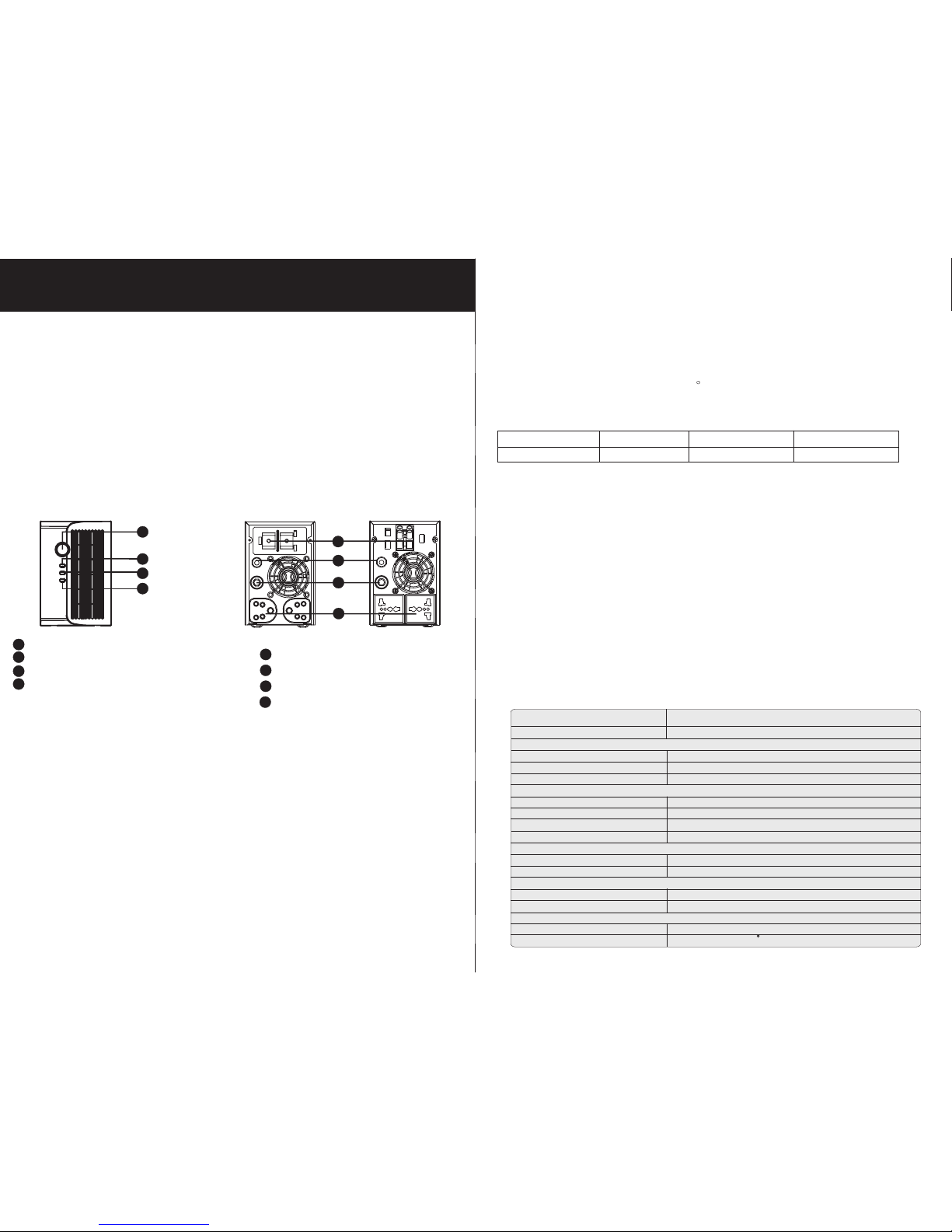
Front View:
Back View:
Pr od uc t Ov erview
2
Atom is a c omp act u nit w hic h com bin es both benefits of UP S and i nverte r for l ong -ti me
op eration. Wi th bu ilt-in volt age s tab ili zer, it w ork s as a UP S to ac cept wide input
volta ge range and co nvert to stab le an d pur e pow er so urc e to th e con nected devices.
Be sid es, i t als o can p rov ide s table power to a various of electronic d evi ces f rom
pe rso nal c omp ute rs, e nergy saving bulbs, televi sio n, to s mal l ind uct ive d evices
su ch as fans . It is p erf ect c hoi ce fo r hom e own ers o r small office users in the u nst abl e
po wer a rea .
1
2
3
4
Power switch
Li ne mo de in dic ato r: gr een l ighting
Ba tte ry mo de in dic ato r: ye llo w flashing
Fau lt in dic ato r: red lighting
1
2
3
4
AC i npu t
Ou tpu t rec ept acl es
Ci rcu it br eak er
Ex ter nal b att ery t erm ina l
2
3
1
4
Im po rt an t Sa fety Warning
(S AVE T HES E INS TRU CTI ONS)
3
Sp ec if ic ations
4
Model Atom 600
CAPACI TY
INPUT
Vol tag e
Vol tag e Rang e
Freque ncy
OUTPUT
Ou tput V olta ge (B att . mode)
Freque ncy R ang e (Batt. mo de)
Tran sfer Time
Wav eform
BATTER Y
Ba tter y Volt age
Ma ximu m Cha rge C urrent
PHYSIC AL
Di mension ( DxW xH mm )
Ne t Weig ht (kgs)
ENVIRO NMENT
Hu midity
Temp erature
600 V A / 300 W
12 V DC
13 A
23 0 VAC
14 0~30 0 VAC
50 H z or 60 Hz
± 10 %
50 H z ± 1 Hz or 60 H z ± 1 Hz
13 m s max.
Si mula ted S ine Wa ve
0- 90 %
0- 40 C (no n-c ond ensing)
35 8.5 X 96 .8 X 146 .5
5. 8
2
4
1
Typi cal A mp. 1 m ete r (on e-w ay) D ia- mm
Atom 60 0 50 A AWG 8 6 .0
Table 1 Minimum Recommen ded B att ery C abl e Siz e versus Length
CAUTION! The unit is desi gne d for i ndo or us e. Do n ot ex pose this unit to rain, snow
or l iqu ids o f any t ype .
CAUTION! To re duc e ris k of in jur y, onl y use q ual ifi ed ba tte ries from qualified
di str ibu tor s or ma nuf act ure rs. A ny un qualified batteries m ay cause d ama ge an d
in jur y. Do NOT u se ol d or ov erd ue ba tte ries. Please check t he ba tte ry ty pe an d dat e
co de be for e ins tal lat ion t o avo id da mag e and i njury.
WARNING! It's very importa nt fo r sys tem s afe ty an d eff ici ent o per ati on to u se
ap pro pri ate e xte rna l bat ter y cable. To reduc e ris k of in jur y, ext ern al ba tte ry ca ble s
sh oul d be UL c ert ifi ed an d rat ed fo r 75 C or h igh er. And D o not u se co pper cables
le ss th an 10 AWG.
Personnel Precaution CAUTION! Careful to reduce the risk or d rop pin g a met al to ol on t he ba tte rie s. It could
sp ark o r sho rt ci rcu it th e bat ter ies and could cause an expl osi on.
CAUTION! Re mov e per sonal metal items su ch as r ing s, br ace let s, ne ckl ace s, and
watch es wh en wo rki ng wi th ba tte rie s. Batteries can produc e a sho rt ci rcu it cu rre nt
hi gh en oug h to ma ke me tal m elt , and c ould cause severe burns.
CAUTION! Av oid t ouching eyes while work ing n ear b att eri es.
CAUTION! Have plenty of fresh water and soap nearby in cas e bat ter y aci d con tac ts
sk in, c lot hin g, or e yes .
CAUTION! NEVER smo ke or allo w a spa rk or f lam e in vi cin ity o f a batter y.
CAUTION! If a remote or aut oma tic g ene rat or st art s yst em is u sed, disable the
au tom ati c sta rti ng ci rcu it or disconnect the gene rator to p revent a cci den t dur ing
se rvi cin g.
CAUTION! Do not disasse mbl e the i nve rte r. Co nta ct wi th th e qua lif ied service center
wh en se rvi ce or r epa ir is r equ ire d.
WARNING! Provide ventilatio n to ou tdo ors f rom t he ba tte ry co mpa rtm ent. The
ba tte ry en clo sur e sho uld b e des igned to prevent accumulation a nd co nce ntr ati on
of hydrogen gas a t the t op of t he co mpa rtm ent .
CAUTION! Use insul ate d too ls to r edu ce th e cha nce o f short- cir cui t when installi ng or
wo rki ng wi th th e inv ert er, the b att eri es, o r oth er eq uipments attached to this un it.
CAUTION! Fo r bat ter y installation and main ten anc e, re ad th e bat ter y man ufa ctu rer 's
in sta lla tio n and m ain tenance instruct ion s pri or to o per ati ng.
3
India Typ e Uni ver sal Typ e
Page 2
Tr ou bl e Sh oo ti ng
6
Us e the t abl e bel ow to s olv e min or pr oblems.
+
-
+
-
5
In st al la tion
NOTE: Before insta lla tio n, pl eas e ins pect the unit. Be s ure t hat
no thi ng in sid e the p ack age i s damaged.
Connect to Utility an d Cha rge
Pl ug in t he AC i npu t cor d to th e wal l out let . The unit will automa tic all y cha rge t he
co nne cte d ext ern al ba tte ry even th ough the unit is off.
Connect External Ba tte ry
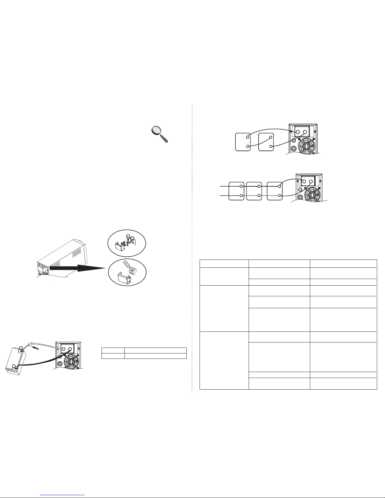
St ep 1- Tak e away the c over of ex ter nal b att ery t erm ina l.
St ep 2- F ollowing battery polari ty gu ide p rin ted n ear t he battery terminal!
RED cab le to t he po sit ive t erm ina l (+) ;
BLACK cable to the negati ve te rmi nal ( -).
WARNING! Please us e the a ppr opr iat e bat ter y cab le. P lease refer to Import ant
Safety Warnings Sectio n for t he de tai ls.
St ep 3- T her e are t wo te rmi nal t ype s.
Type 1 : Scr ew batte ry cables to termina ls wi th th e M5 nu ts. D o NOT p lac e
anything between t he fl at pa rt of b att ery t erm inal and the battery
cable ring t erm ina l, or o ver hea tin g may o ccu r.
Type 2 : Simply screw battery cables to te rmi nal w ith f lat s cre wdrive r.
(S ee Fi g. 1)
St ep 4- I nst all a D C Bre ake r in a po sit ive b att ery line. The rating of the DC
Breaker mu st be a cco rdi ng to t he in ver ter 's ba tte ry cu rre nt (5 0 Amp). Ke ep
the DC breaker off. (see Fig. 2)
St ep 5- C onn ect b att ery c abl es to t he external batteries .
Note: Fo r the user operation safety, we st ron gly r eco mme nd th at yo u should use tapes
to i sol ate t he ba tte ry te rmi nal s before y ou st art to operat e the unit.
1)Single battery co nne cti on( Ref er to F ig. 2 ): Wh en us ing a s ing le ba tte ry, it s
volta ge mu st be e qua l to th e Nom ina l DC Volta ge of t he un it (s ee be low Table 1).
2)Multiple batter ies i n ser ies c onn ect ion (Refer to Fig. 3): All batteries mus t
be e qua l in vo lta ge an d amp h our c apa city. The s um of t hei r vol tag es mu st be equal
to t he no min al DC Vo ltage of the unit.
3)Multiple batter ies i n par all el co nne cti on(Refer to Fig. 4): Each battery's
volta ge mu st be e qua l to th e Nom ina l DC Volta ge of t he un it.
St ep 6- M ake s ure t o con nec t the p ola rity of ba tte ry side and the unit correc tly.
Positive pole (Red) of battery to the positive term ina l (+) of th e uni t.
Negat ive p ole ( Bla ck) o f bat ter y to th e negative terminal (-) of the u nit .
St ep 7- P ut th e cov ers b ack t o the e xte rna l battery terminals.
St ep 8- Tak e the D C bre ake r on.
Mo del N omi nal B att ery D C Voltage
Atom 60 0 12VDC
Table 1
+
-
+
-
+
-
Fig. 4
DC
breake r
+
-
+
-
+
-
Fig. 3
Problem Probable Ca use S olu tio n
Ut ili ty po wer i s
no rma l but t he un it
is i n batter y mod e.
Wh en po wer f ail s,
th e bac kup t ime i s
sh ort en.
No L ED di spl ay on
th e fro nt pa nel w hen
th e uti lit y pow er is
no rma l.
AC i npu t pow er co rd is n ot
co nne cte d wel l.
Input b rea ker i s act ivated .
Th e uni t is ov erl oad .
Ba tte ry vo lta ge is t oo lo w.
Ba tte ry ca pac ity i s not f ull
even af ter c har ge th e uni t
for at least 8 h our s.
Th e uni t is no t tur ned o n.
Ba tte ry is n ot co nne cte d
we ll.
Ba tte ry de fec t.
Ba tte ry vo lta ge is t oo lo w.
Ch eck A C inp ut po wer
co nne cti on.
Reset the input b rea ker.
Remove some non-criti cal
lo ads .
Ch arg e the u nit a t lea st
8 ho urs .
Ch eck t he da te co de of t he
ba tte ry. If the batteries
are too o ld, r epl ace t he
ba tte rie s.
Press p owe r swi tch t o tur n
on t he un it.
Ch eck t he ex ter nal b att ery
ca ble a nd te rmi nal . Mak e
su re al l the b att ery
co nne cti ons t o the u nit a re
al l cor rec t.
Replace the batter ies .
Ch arg e the u nit a t lea st
8 ho urs .
+
-
+
-
Fig.1 Battery cable c onn ect s to th e ter min al
Type 1
Type 2
Fig. 2
 Loading...