

Voltronic VCC 1212-25 IUoU-Li, 3306, 3308, VCC 2412-25 IUoU-Li, VCC 1212-45 IUoU-Li Operating Manual
...Page 1

Installation and Operating Manual
Charging Converter, B2B Battery to Battery, Battery Charging During Driving:
VCC 1212-25 IUoU-Li Input Voltage 12 V Charging Capacity 12 V / 25 A No. 3306
VCC 1212-45 IUoU-Li Input Voltage 12 V Charging Capacity 12 V / 45 A No. 3308
VCC 2412-25 IUoU-Li Input Voltage 24 V Charging Capacity 12 V / 25 A No. 3314
VCC 2412-45 IUoU-Li Input Voltage 24 V Charging Capacity 12 V / 45 A No. 3315
Please read the mounting instructions and the operating manual including the safety
instructions attentively. Particularly observe page 2 "Safety Regulations and Appropriate
Application", prior to starting connection and start-up.
Fully automatic Battery Charging Converter for special purpose vehicles, campers, boats.
The charging converters (boosters) had been developed according to the latest regulations for supply battery charging in
lead-acid, lead-gel, lead-AGM or LiFePO4 technology from the generator during driving.
In case of long supply lines or insufficient cross-sections of the cables, the charging voltage will be increased according to
the default charging values and losses will be compensated. Charging converters with 24 V input voltage allow charging of
the 12 V supply battery without installation of a second generator.
Thus, the charging converter ensures the known high-quality battery charging of the VOTRONIC chargers also during
driving. Due to the intelligent microprocessor charging control with charging characteristic lines "IU1oU2" and dynamic
charging time calculation an automatic, quick and gentle full charging is ensured, as well as subsequent 100 % trickle charge
of the connected batteries from any charging state. At the same time, simultaneous supply of 12 V consumers, which are
connected in parallel, is ensured. Overcharging or excessive gassing of the batteries is avoided, even in case of extremely
long driving times. Any consumed energy will be compensated immediately.
The charging converters excel by their compact design, low weight (high-frequency switch mode technology), powerfully
dimensioned power components and consequently full charging capacity, even with long charging cables or strong voltage
fluctuations at the generator / starter battery (EURO standard 6, 6 + plus vehicles).
Information see page 9, table 2, switch position "D".
Battery Output OUT "I", Charging Programs:
Depending on the battery type, select one of the 4 charging programs, see table 1:
a) "Lead Acid/AGM1": Closed and open acid/lead-acid-lead batteries, as well as AGM 14.4 V (factory adjustment)
b) "AGM 2": Closed, gas-tight AGM batteries (absorbed glass mat, lead-fleece technology)
c) "Gel": Closed, gas-tight Gel batteries, (dryfit, determined electrolyte)
d) "LiFePO4": Charging voltage 14.4 V for lithium LiFePO4 batteries with completely integrated electronic system
and safety circuit (BMS).
Further Characteristics of the Unit:
The charging voltage is free from peaks and is controlled in such a way, that overcharging of the batteries is excluded.
Fully automatic operation by means of control input (ignition, running engine), as well as voltage control.
No intervention into the electric system of the vehicle. The charging converter acts like a consumer at the generator.
Automatic, adjustable power control giving priority to charging of the starter battery by the generator in case of
overloaded vehicle mains to ensure that the vehicle can be started at any time.
No discharge (current 0.000 A) of the batteries during stand-by or with switched-off charging converter.
Parallel and Floating Operation: In case of simultaneous consumption, the battery will either continue to be charged
or maintained via trickle charging. Calculation and control of the adaptation of the charging time is effected
automatically by the charging converter.
Unattended Charging: Multiple protection against overload, overheating, overvoltage, short circuit, reverse battery at
the output, incorrect behaviour and back discharge of the battery by electronically controlled gradual reduction down
to complete separation of charging converter and battery by integrated safety relays.
Galvanic isolation between input and output: Complete separation of the battery circuits, even in case of failure
(particularly important for 24 V/12 V mixed systems) and neat ground ratio, also in case of long supply lines.
Charging aid for deeply discharged lead batteries or switched-off LiFePO4 batteries: Gentle preliminary charging of
the (lead-acid, gel, AGM) battery or automatic reactivation of the Li battery in case of possibly switched-on consumers.
Page 2
- 2 -
Lead Temperature Equalization: The delivered battery temperature sensor effects an automatic adaptation of the
charging voltage to the battery temperature. In case of low outside temperatures, full charging of the weaker battery is
improved, and in case of summery temperatures unnecessary battery gassing will be avoided.
LiFePO4 temperature control and adaptation of the charging by the delivered battery temperature sensor, which allows
also charging beyond the recommended LiFePO4 battery temperatures below 5 °C and above 35 °C.
Integrated On-board Mains Suppression Filter: Unproblematic parallel operation of solar systems, wind and petrol-
driven generators, mains supply chargers etc. at a single battery.
Charging Cable Compensation: Automatic compensation of voltage losses on the charging cables.
Battery Lifetime and Efficiency:
Keep the batteries cool, LiFePO4 preferably above 0 °C. Choose an appropriate location
for installation.
Store only fully charged batteries and recharge them periodically.
Open lead-acid batteries and batteries being "maintenance-free according to EN / DIN":
Check the acid level periodically!
Recharge deeply discharged lead batteries immediately!
LiFePO4: Only use complete batteries with BMS and safety circuit.
! Deep discharge is to be absolutely avoided !
Safety Regulations and Appropriate Application:
The charging converter has been designed according to the valid safety regulations.
Appropriate application is restricted to:
1. Charging of lead-gel, lead-AGM, lead-acid or LiFePO4 complete batteries (with integrated BMS,
balancing, safety circuit and approval!) Charging of batteries of the indicated nominal voltage and
simultaneous supply of the consumers being connected to these batteries in fixed installed systems with
the indicated battery capacities and charging programs.
2. Connection in consideration of the indicated cable cross-sections at the inputs and outputs of the
charging converter.
3. With the indicated minimum battery capacity at the input of the charging converter.
4. Fuses of the indicated capacity are to be provided near the battery to protect the cabling between
battery and connections of the charging converter.
5. Technically faultless condition.
6. Installation in a well-ventilated room, protected from rain, humidity, dust, aggressive battery gases, as
well as in an environment being free from condensation water.
Never use the unit in locations where the risk of gas or dust explosion exists!
Open-air operation of the unit is not allowed.
Lay the cables in a way, that damage is avoided and observe to fasten them tightly.
Never lay 12 V (24 V) cables and 230 V mains supply cables into the same cable conduit (empty conduit).
Check live cables or leads periodically for insulation faults, points of break or loosened connections. Occurring
defects must be remedied immediately.
The unit is to be disconnected from any connection prior to execution of electrically welding or work on the
electric system.
If the user is not able to draw from the manual, which characteristic values are valid for a unit or which
regulations are to be observed, a specialist is to be consulted.
The user / buyer is responsible for the observation of construction and safety regulations of any kind.
The unit does not contain any parts, which can be replaced by the user. Even after having been switched-off,
the unit may be live for an extended period (particularly in case of failure).
Keep children away from the charging converter and the batteries.
Observe the safety regulations of the battery manufacturer; deaerate the battery room.
Non-observance may result in injury or material damage.
The warranty period is 36 months from the purchase date (against presentation of the sales slip or invoice).
The warranty will be void in case of any inappropriate utilisation of the unit, if it is used beyond the technical
specification, in case of improper operation or external intervention. We do not assume any liability for any
damage resulting hereof. The liability exclusion is extended to any service being executed by third, which has
not been ordered by us in writing. Service is to be effected exclusively by VOTRONIC Lauterbach.
Page 3

- 3 -
Installation of the Unit:
The charging converter can be installed at any location, which is clean and which is protected from humidity and dust.
Choose an installation location ensuring that the length of the connection cable between starter battery (IN) and board
battery (OUT) is as short as possible. By this, unnecessary losses over the cables are avoided.
Despite the charging converter’s high efficiency, heat is produced, which is brought out of the casing by means of the builtin fans.
Ensure sufficient ventilation in the environment of the unit, so that the heat can be removed. Protect the unit from
aggressive battery gas.
The unit can be installed in any position. However, the vent holes of the casing (front panel and rear panel) should never be
covered to ensure the full charging capacity (minimum distance: 10 cm).
Ensure a solid and vibration reducing installation using rubber bushings on an even and hard mounting surface.
Connection and Settings:
Choose the suitable connection plan according to your application. Observe the indications, fuses, polarity
+/-!
Table Page 5: Observe the "Recommended Cable Cross-sections and Lengths of the Power Connection
Cable"!
First connect the charging converter, after that the batteries.
Output Side:
1. Connect the board/supply battery to the large terminals "Battery I OUT" "-" and "+" observing the correct
polarity. Recommended in case of a cable length exceeding 2 m:
Lead a voltage sensor line with fuse directly from the positive pole of the board battery to the terminal
"+ Sense Out". Recommended in case of a cable length of less than 2 m: The terminal "+ Sense Out" can be
left free.
2. Terminals "T T Temp. Sensor": Connect the temperature sensor (included in the delivery scope) for
battery temperature equalization and control. See "Option Temperature Sensor", page 7.
Input Side:
3. Connect the vehicle's starter battery to the large terminals "Battery II IN" "-" and "+" observing the
correct polarity! Reverse battery (mixing up) +/- at this place will result in serious damage of the unit!
4. Terminal "Sense In+": Lead a voltage sensor line with fuse directly from the positive pole of the starter
battery. Without connection, the unit does not work!
For further details (such as operation without separate sensor line) please refer to table 2, page 9.
5. Terminal "Kl.15/D+", control input for activation of the unit:
Connection preferably to the signal D+ "Generator active" of the vehicle.
If this signal does not exist, the signal "Ignition ON" (vehicle terminal 15) can be used for automatic unit
control.
6. Terminal "EBL Start In": Refer to connection plan "EBL" and "EVS", otherwise leave it free.
Settings for Start-up:
7. Output Side of the Charging Converter:
Set the type, design (lead-acid, AGM, gel or Lithium-LiFePO4) of the board battery "I" to be charged using
the switches "Battery Type". See table 1, page 8.
8. Input Side of the Charging Converter:
Set the installation operating mode IN at the starter battery "II" to be supplied by means of the switches
"Input Type". See table 2, page 9.
9. Start-up and function test, see page 10. Further details, see page 11.
Further operation of the unit is not required during normal automatic mode.
Page 4

- 4 -
General Connection Plan Charging Converter, All Types:
If possible, the unit should always be installed as close as possible to the board battery I.
Observe the cable cross-sections, lengths and fuses according to the table on page 5!
Possibly existing cables, which do not have the required cross-sections must be adapted to the
minimum requirements in any case!
Reverse battery (+/-) at the IN II (Start) side will result in serious damage of the unit!
Input and output side of the charging converter are separated by galvanic isolation, i. e. there is no conductive
connection between the input II side (START) and the output I side (BOARD).
Thus, the two battery circuits are completely independent of each other, and a mutual influence or disturbance
is avoided.
Therefore, the minus (-) terminals I and II must imperatively be connected observing the indicated cable crosssections. Refer to connection plan.
If required, the two sensor lines "Sense In +" and "+ Sense Out" (see table2) must be led separately and as
separate line to the + poles of the battery!
This is the only way to achieve a correct voltage measurement at the batteries.
The sensor lines near the battery must be protected with a fuse (cable protection)!
Page 5
- 5 -
Recommended Cross-sections and Lengths of the Power Connection Cables:
Cable
Cross-
sections,
each
+ / - Pole
VCC 1212-25
VCC 1212-45
VCC 2412-25
VCC 2412-45
START
Batt.
BOARD
Batt.
START
Batt.
BOARD
Batt.
START
Batt.
BOARD
Batt.
START
Batt.
BOARD
Batt.
Fuse II:
40 A
Fuse I:
30 A
Fuse II:
80 A
Fuse I:
50 A
Fuse II:
30 A
Fuse I:
30 A
Fuse II:
40 A
Fuse I:
50 A
Cable
Length:
Cable
Length:
Cable
Length:
Cable
Length:
Cable
Length:
Cable
Length:
Cable
Length:
Cable
Length:
4 mm²
-
0.5 - 2.0 m
-
-
up to
6.0 m
0.5 - 2.0 m
-
-
6 mm2
up to
5.5 m
1.5 - 3.5 m
-
0.5 - 2.0 m
up to
11.0 m
1.5 - 3.5 m
up to
6.0 m
0.5 - 2.0 m
10 mm2
up to
9.0 m
3.0 - 6.5 m
up to
5.0 m
1.5 - 3.5 m
up to
18.0 m
3.0 - 6.5 m
up to
10.0 m
1.5 - 3.5 m
16 mm2 - -
up to
8.0 m
3.0 - 5.0 m
-
-
up to
16.0 m
3.0 - 5.0 m
* * Insert the cable into the terminal without wire-end ferrule
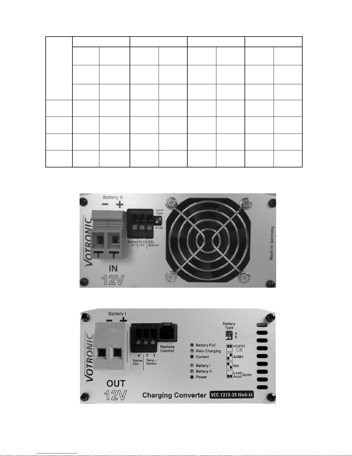
View Front Panel Input
View Front Panel Output
Page 6

- 6 -
Connection Plan VCC 1212-25, VCC 1212-45 including:
VOTRONIC charger with separate charging port for starter battery
VOTRONIC solar charging controller with separate charging port for starter battery
If possible, the unit should always be installed as close as possible to the board battery I.
Observe the cable cross-sections, lengths and fuses according to the table on page 5!
Possibly existing cables, which do not have the required cross-sections must be adapted to the
minimum requirements in any case!
Reverse battery (+/-) at the IN II (Start) side will result in serious damage of the unit!
Page 7

- 7 -
Option: Temperature Sensor (Connect the delivered temperature sensor):
Connect the temperature sensor to the terminals "T T Temp. Sensor" (any polarity).
It serves for control of the temperature of the BOARD supply battery. Also refer to page 15
"Charging Voltage Rates and Temperature Equalization/Control of the Battery Board I".
Ensure that the installation place of the sensor is not influenced by any source of heat (engine heat, exhaust, heater
etc.)!
Lead-Acid, Gel, AGM Batteries:
Installation: The thermal contact of sensor and battery inside temperature should be well. Thus, it should be screwed
down to the negative pole or positive pole of the battery. It is also possible to fasten it at the sidewall centre of the bat tery
casing.
Function: The temperature-dependent charging voltage of the BOARD battery will be adapted automatically to the battery
temperature (automatic temperature equalization). For this purpose, the temperature sensor measures the battery
temperature. In case of low temperatures (winter operation), the charging voltage will be increased, in order to improve
and accelerate full charging of the weak battery. Sensitive consumers are protected by a voltage limitation in case of very
low outside temperatures.
In case of summery temperatures, the charging voltage is reduced to minimize the load (gassing) of the battery and to
extend the lifetime of gas-tight batteries.
Battery Protection: In case of excessive battery temperatures (from +50 °C), the charging voltage will be reduced strongly
to the safety charging voltage, approx. 12.80 V, for battery protection, and the maximum charging current rate will be
halved (safety mode, LED "Battery I" is flashing. Any charging data being recorded hitherto will be kept in memory. Battery
charging is then interrupted, but the supply of possibly connected consumers will be continued by the unit, and the battery
is allowed to cool down. After that, automatic charging is resumed.
The unit recognizes automatically a missing sensor, cable break or short circuit of the sensor cables, as well as unreasonable
measuring values. In that case, it will switch automatically to the usual charging voltage rates of 20 °C / 25 °C being
recommended by the battery manufacturers.
LiFePO4 Batteries:
Installation: The thermal contact of sensor and inside temperature of the battery should be well. Thus, it should be
screwed down to the negative pole of the battery, because in most of the cases, this is the cooler side (the positive pole is
often biased by the exhaust heat of internal fuses of the battery, electronic systems for cell equalization, balancers etc.)
Function: In case of abnormal battery temperatures, such as < -20 °C, > 50 °C, the charging voltage will be reduced strongly
to the safety charging voltage, approx. 12.80 V, for battery protection, and the maximum charging current rate will be
halved (safety mode, LED "Battery I" is flashing). Any charging data being recorded hitherto will be kept in memory.
Battery charging is then interrupted, but the supply of consumers being possibly connected will be continued by the
charger until the battery temperature is again within the acceptable range. After that, automatic charging will be resumed.
Below 0 °C, the charging current will be reduced more strongly for battery protection, LED "Battery I" turns off shortly
every 2 seconds and longer charging times can be expected.
Warning: If the charging characteristic line had been set for a LiFePO4 battery, the temperature sensor
must be connected for reasons of battery safety. Otherwise, the unit will not operate, and the LED "Main
Charge" will be flashing!
Option: Remote Control (Tip Jack "Remote Control")
If the charging converter has been installed in a difficult to access location, the Remote Control S
for Automatic Charger, order No. 2075, can be used for remote control of the charging process
(plug-and-go connection cable of 5 m length is included in the delivery scope).
Connection:
Connect the remote control to the tip jack "Remote Control".
Function:
The remote control is equipped with the same pilot lamps (light-emitting diodes) as the charging
converter.
Switch Function:
Position "ON": Charging converter works with full charging capacity. LED display is active.
Position "OFF": Charging converter is switched-off (stand-by).
Page 8

- 8 -
Table 1: Setting of the Charging Program OUT for Type (Design) Board Battery I:
Move the 2 slide switches "Battery Type" OUT 12 V (24 V) at the front panel to the desired position for
board battery "I" using a small screw-driver. (Factory-adjusted position "Lead Acid"=Lead Acid Battery).
The control levers are shown in white.
Battery
Type
Selector
Switch
Output Side of the Converter:
If not being specified divergently by the battery manufacturer, the suitable charging program
for the battery type (design, technology) can be determined by means of the following
description and the technical data (voltage rates U1 and U2).
Note: The possible parallel/floating operation with consumers being
connected to the battery is also automatically considered by all charging programs.
"LiFePO4": 14.4 V Lithium charging program, adapted to
types, such as Super B SB12Vxx - M (Epsilon) **, RELION types RB **, Büttner types "MT-Li XX",
all with integrated battery management system and integrated safety circuit!
** also to be used with indication "Charging Voltage: 14.6 V", because of the lower battery load.
Check Super B SB12VxxE, GNB/Exide SL12 xxxHC with BMS and other batteries for their suitability
for 14.4 V charging voltage and only use them with completely own BMS and prescribed safety circuit!
LiFePO4 Charging Program IU1oU2:
U1 Main/Full Charging: 14.40 V 20 °C 0.3-1 h
U2 Full/Trickle/Storage Charging: 13.80 V 20 °C Continuous
"AGM 2": Charging program for lead, AGM/fleece batteries:
Adapted to closed, gas-tight AGM (absorbed glass mat) batteries and batteries in lead-fleece
technology requiring a particularly high level U1 for full charging.
voltage U1 14.7 V.
Unsuitable batteries might age prematurely due to loss of electrolyte!
Some manufacturers of AGM/fleece batteries are also prescribing a "gel" or "acid"
charging program with a charging voltage of 14.4 V for charging! In these cases, set
"Lead Acid / AGM 1" (14.4 V/13.50 V).
Charging program AGM/Fleece IU1oU2:
U1 Main/Full Charging: 14.70 V ! 20 °C 0.5-4 h
U2 Full/Trickle/Storage Charging: 13.60 V 20 °C Continuous
"Gel": Charging program for lead gel/dryfit batteries:
Adapted to closed, gas-tight Gel batteries with determined electrolytes, which are generally requiring a
higher charging voltage level and longer dwell times U1 to achieve short charging times with
particularly high capacity storage and to avoid deep discharge, e. g. EXIDE, Sonnenschein dryfit- Start,
Dryfit-Sport-Line, DETA Gel Battery Funline, Bosch AS Gel Batteries Va/Z, AS Gel Drive Batteries, AS Gel
Lighting Batteries.
If not being specified divergently by the battery manufacturer, also recommended for batteries in
round cell technology, such as EXIDE MAXXIMA (DC).
EXIDE, DETA, VARTA Characteristic Line Gel IU1oU2:
U1 Main/Full Charging: 14.40 V 20 °C 4-10 h
U2 Full/Trickle/Storage Charging: 13.80 V 20 °C Continuous
"Lead Acid/AGM 1": Universal charging program for acid/lead-acid batteries:
For charging and trickle charging of supply (board) batteries. Ensures short charging times, high
charging factor and acid mixing for open standard batteries and closed, low-maintenance,
maintenance-free "non-solid electrolyte", "lead-acid", drive, lighting, solar and heavy-duty batteries.
Also suitable for recently developed batteries (low-antimonous, batteries with silver alloy,
calcium/calcium or similar) with low and very low water consumption, as well as AGM batteries with
the designation 14.4 V.
Universal charging program IU1oU2:
U1 Main/Full Charging: 14.40 V 20 °C 0.5-4 h
U2 Full/Trickle/Storage Charging: 13.50 V 20 °C Continuous
Page 9

- 9 -
Table 2: Setting the Input, Installation Operating Mode IN II at the Starter Battery:
Power Control for Starter Battery and Generator
Move the 2 slide switches "Input Type S1, S2" IN II 12 V (24 V) at the front panel to the desired position
for Starter Battery "II" using a small screw-driver.
The control levers are shown in white.
Input
Type
Selector
Switch
Input side of the converter (at the starter battery for protection against LiMa peaks):
The operating range of charging converter must be set for the operating mode (control
connection, switching thresholds) and the mode of installation (cable lengths to the starter
battery). Also refer to: "Function of the Power Control for Starter Battery and Generator",
page 10.
A. Pure voltage control of the charging converter, without separate control signal "Kl.15 / D+":
Because of the high voltage thresholds, only to be used with separately laid "Sense In +" line,
sufficiently dimensioned cable cross-sections and powerful generator. The starter battery will not be
discharged under any circumstances.
Control connection "Kl.15 / D+" must be connected to "Sense In" via a wire jumper !
Increase of the charging capacity: > 13.60 V (27.2 V)
Reduction of the charging capacity: < 13.20 V (26.4 V)
Switching off threshold charging converter: < 12.60 V (25.2 V) 30 sec.
B. Slight load on the starter battery:
Only use these voltage thresholds with separately laid "Sense In +" line, sufficiently dimensioned cable
cross-sections and powerful generator.
Note: A continuous signal at "Kl.15 / D+" without running motor might discharge the STARTER battery!
Increase of the charging capacity: > 13.20 V (26.4 V)
Reduction of the charging capacity: < 12.80 V (25.6 V)
Switching off threshold charging converter: < 12.20 V (24.4 V) 30 sec.
C. Without sense line "Sense In +" of the starter battery:
If the cross-sections of the cables to the starter battery are sufficiently dimensioned, a separately laid
line "Sense In+" is not required. A wire jumper must be laid from "IN +" to "Sense In +"!
Note: A continuous signal at "Kl.15 / D+" without running motor might discharge the STARTER battery!
Increase of the charging capacity: > 13.40 V (26.8 V)
Reduction of the charging capacity: < 12.80 V (25.6 V)
Switching off threshold charging converter: < 12.20 V (24.4 V) 30 sec.
D. Vehicles according to EURO Standard 6, 6+ and for parallel operation of 2 charging converters:
If the cable to the starter battery is short (<2 m) and the cable cross-section is sufficiently
dimensioned, a separately laid voltage sensor line "Sense In+" is not required.
However, in this case a wire jumper is required for connection of "Sense In+" to "IN+".
This switch position is also provided for EURO standard 6, 6+ vehicles with energy management,
start/stop automatics, strongly varying voltage of generator/starter battery during energy recovery
etc.). If the cables are very long (losses), a separate voltage sensor line from the + starter battery to
"Sense In+" might be advantageous.
Always use the control input "Kl.15 / D+", and either connect it to KL.15 (ignition ON) or more safely to
D+ of the vehicle (generator is "active"), since in case of a continuous signal without running motor the
starter battery can be strongly discharged!
Increase of the charging capacity: > 11.70 V (26.0 V)
Reduction of the charging capacity: > 11.40 V (24.8 V)
Switching off threshold charging converter: < 11.20 V (23.6 V) 30 sec.
Option: Parallel Connection of 2 Charging Converters:
An increase of the charging capacity for large battery systems or high loads (such as operation of an air-conditioning
system) can be realized by parallel connection of two identical units. Couple the connections and set both units to switch
position "D" according to table 2.
A separately laid voltage sensor line from starter battery + (plus) is then to be distributed to the "Sense In +"
inputs of the units, particularly for Euro Standard 6 vehicles.
Due to the occurring high current rates, the required cable cross-sections of the power supply connections must
be multiplied by two, or they must be observed absolutely in case of separate laying.
Page 10

- 10 -
Start-up and Function Test:
After connection and setting of the charging converter the function can be tested:
1. Start the vehicle or switch on ignition (Kl.15).
- The charging converter will be activated and starts with 10 % of the maximum charging capacity.
- The LEDs "Power”, "Battery I”, "Main Charging” will be lighting, LED "Current” is lighting dimly.
2. Increase the speed of the vehicle to increase the voltage at the starter battery until it exceeds the adjusted value for
the "increase of the charging capacity".
- The charging capacity will be increased and is raised to the maximum value or to the required value of the charging
characteristic line, if the board battery is already full.
- The lighting intensity of the LED "Current" will be reduced or increased depending on the charging current.
Function of the Power Control for Starter Battery and Generator:
The charging converter is activated by the control input "Kl.15 / D+" and will be deactivated automatically if the motor is
switched-off. It starts with 10 % of its achievable charging capacity.
The setting of the two slide switches "Input Type" on the unit's rear (see table 2) now affects the further load of the starter
battery circuit supplying current to the charging converter.
After the engine start, also the starter battery shall be charged immediately and its starting capacity shall be maintained.
Therefore, the gradual increase of the charging capacity for the board battery will not be effected before the voltage value
"increase of the charging capacity" of the starter battery is reached.
In case of strong load on the starter circuit due to many large consumer loads and the starter battery’s voltage drops below
the value "reduction of the charging capacity", such as during motor idling, there will be a gradual reduction of the chargin g
capacity for the battery Board I, to relieve the starter circuit. But the minimum charging capacity will always be at least
10 % of the achievable charging capacity.
If the voltage drops below the "Switching off threshold charging converter" for 30 sec., the charging converter will be
switched-off automatically. As soon as the voltage exceeds the threshold "increase of the charging capacity", the converter
will be switched-on, and the capacity will be increased gradually until the required (maximum) charging capacity is reached.
A reduction of the charging capacity by more than 30 % due to insufficient input voltage of the dynamo will be indicated by
a flashing LED "Battery II". The LED will turn off, as soon as the input voltage is sufficient or when the power requirement
had dropped anyway due to a charged board battery "I".
Pilot Lamps:
"Battery Full" (Board battery fully charged, green):
If it is on: Battery has been charged to 100 %, trickle charge U2, finished.
If it is flashing: Main charging process is effected in the charging phase U1,
indication of charging state of approx. 80 % (short flashing, 90 % LiFePO4), gradual increase
to 100 % (long flashing).
Off: Main charging process is still being executed in the phase I.
"Main Charging" (Main charging board battery, yellow):
If it is on: Main charging process is effected in the charging phase I or U1.
Off: Trickle charge U2.
If it is flashing: 1. Battery temperature sensor is not connected with charging characteristic lines LiFePO4!
2. External battery overvoltage > 15.5 V delay 20 s,
Automatic reset < 13.2 V (depending on type), delay 30 s.
"Current" (Charging Current, red):
If it is on: The lighting intensity will be reduced or increased depending on the supplied charging
current.
Off: The instantaneous charging current is less than approx. 0.2 A.
"Battery I" (Board battery, yellow):
If it is on: Control and charging of board battery "I".
If it is flashing: Battery protection: Battery overtemperature > 50 °C, switching to
low safety charging voltage and half of the max. charging current,
automatic return, in case of slight cooling down to 48 °C,
with LiFePO4 also at low temperature of the battery < -20°C.
If it turns off shortly Only LiFePO4: Battery temperature below 0 °C. The charging current can be reduced for battery
every 2 s: protection for all modes of charging. If the battery is discharged, longer charging times.
Off: Board battery "I" is separated from the charging converter (safety switch).
Page 11

- 11 -
"Battery II" (Starter Battery, yellow):
If it is flashing: The power control of the charging converter has reduced the output capacity by more than
30 % (starter battery discharge protection, starting capacity is maintained), since the voltage of
the starter battery dropped below the adjusted value for "Reduction of the charging capacity"
(table 2). The charging capacity will be increased again, as soon as the voltage exceeds the
value "increase of the charging capacity".
"Power" (red):
If it is on: The charging converter had been activated and is ready for operation.
If it is flashing: 1. Disconnection by safety timer. Duration of the charging phase I was too long (15 hours) due to
too many consumers or defective battery (short circuit of the cells).
Reset only by removal of the signal at "D+ / Kl.15" (engine, ignition off).
2. Internal unit failure (overheating), automatic reset after cooling down.
3. Reverse battery of the battery board I by mistake (+ and - are mixed up).
Operating Instructions:
Interruption of the charging process:
If the control signal D+ or Kl.15 fails or the starter battery is drawn below the adjusted switching off threshold during
the charging process, the charging process will be interrupted. The connected batteries will not be discharged by the
charging converter. In this way, the charging process can be interrupted at any time. In case of frequent interruptions,
particularly before reaching full charge (LED "Battery Full" is lighting permanently), the battery should be subject to an
occasional full charging cycle of 24 hours for equalization of the charge.
Lifetime lead battery: Partially discharged lead batteries:
In contrast to other battery types, batteries on lead basis do not have any harmful memory effect. Consequently: In
case of doubt, partially discharged batteries have to be charged fully as soon as possible.
Store only fully charged batteries and recharge them periodically, particularly in case of used (older) batteries and
higher temperatures.
Lifetime lead battery: Recharge deeply discharged batteries immediately:
Sulphation of the battery plates due to deep discharge is to be prevented by immediate charging, particularly in case
of low and high ambient temperatures. If the grade of sulphation is not too intensive, the battery can recover part of
the battery capacity after several charging/discharging cycles.
Output overvoltage limitation at the board battery I (OUT):
Sensitive consumers are protected by means of a limitation of the charging voltage to max. 15.0 V during all modes of
charging, independently of the input voltage, charging programs etc.
Output overvoltage limitation at the board battery I (OUT):
Charging converters protect themselves against connection of excessive battery voltage rates, or they are switched-off
in case of defective additional charging systems (solar systems, generators etc.) switching threshold 15.5 V, delay 20 s.
Reset by battery <12.8 V (<13.4 V LiFePO4) or by disconnection of the control signal D+ or Kl.15.
Input overvoltage protection at the starter battery II (IN):
According to the EURO standards, the units supply uniform output voltage rates and output current rates in case of
varying input voltage rates. Extreme overvoltage of > 16.5 V (32.2 V) in the starter circuit causes a disconnection.
Overload/Overheating Protection Charging Converter:
The charging converter is equipped with a double electronic protection against overload and with an automatic
protection against adverse installation conditions (e. g. insufficient ventilation, excessive ambient temperatures) by
gradual reduction of the charging capacity.
Tips:
The unit is not activated with running motor:
Check the voltage rates, directly between terminal "Battery II –" and: Measure "+", "Sense In+" and "Kl. 15/D+",
fuses, wiring "+" and "–", stripped cable ends / at the clamping screws.
Full charging current is not reached:
Full charging is not effected, since the voltage is too low between terminal "Battery II –" and: "+", "Sense In+":
Observe the cable cross-sections and cable lengths, check the fuses, check the switch position S1, S2 according to table 2.
Insufficient voltage supply to "Sense In+" from a distributor or the like: Put the line to plus starter battery.
Concealed cutoff relay (such as EBL, EVS) bridges the charging converter: Check connection plan.
Battery Board I had been already charged: Turn on devices with high current draw.
Charging cable to board I: Check the cross-section and the length, check the fuses, if required, lay sensor line "Sense
Out+".
Downstream current distribution equipment or control units are not working correctly:
For instance, the signal D+ is not supplied: Ground (minus) connection between starter and board battery is missing.
Operation with EBL:
The charging converter changes permanently between active and stand-by: "Kl. 15/D+" must be connected directly to
the input EBL-D+ coming from the generator/electronic system of the vehicle.
Page 12

- 12 -
Special case: Connection Plan for Existing Electroblock "EBL",
Only for Types VCC 1212-25 Li and VCC 1212-45:
Option: Voltage display at an EBL of older design (EBL START In):
After installation of the charging converter in connection with an EBL of older design, it might happen, that the voltage for
the starter battery will not be displayed, if the charging converter had been switched-off.
In this case, the terminal "EBL START In" is to be connected to the voltage of the starter battery.
If possible, the unit should always be installed as close as possible to the board battery I.
Observe the cable cross-sections, lengths and fuses according to the table on page 5!
Possibly existing cables, which do not have the required cross-sections must be adapted to the
minimum requirements in any case!
Reverse battery (+/-) at the IN II (Start) side will result in serious damage of the unit!
Page 13

- 13 -
Special case: Connection Plan for Existing Electroblock "EVS",
Only for Types VCC 1212-25 and VCC 1212-45:
A special feature of the "EVS" systems is only a single connection to the starter battery, which means, that
separate connections for charging and voltage measurement for the starter battery do not exist.
For this reason, the connections "Sense In +" and "EBL Start In" must be bridged to ensure, that the
starter battery will also be charged during mains charging mode.
Determined by the system, the voltage of the starter battery will not be displayed correctly at the EVS during
driving.
If possible, the unit should always be installed as close as possible to the board battery I.
Observe the cable cross-sections, lengths and fuses according to the table on page 5!
Possibly existing cables, which do not have the required cross-sections must be adapted to the
minimum requirements in any case!
Reverse battery (+/-) at the IN II (Start) side will result in serious damage of the unit!
Page 14

- 14 -
Charging Process of the Board Battery I, Out, Output Side of the Charging Converter:
A new, complete main charging cycle will be executed:
After a standstill of the generator or removal of the control signal D+ or Kl.15.
If the voltage of the starter battery has dropped below the adjusted switching off threshold for more than 30 seconds.
If the battery voltage drops below the reset voltage of approx. 12.8 V (13.4 V with LiFePO4) for 30 seconds due to high
load beyond the maximum charging current.
If the charging converter had been switched-off by means of the remote control and on subsequent restart.
1. Charging aid for deeply discharged lead batteries. From 0 V, they will be subject to gentle preliminary charging for
recovery with a small current rate up to approx. 8 V or a switched-off LiFePO4 battery will be reactivated.
2. Main charging with maximum charging current (phase I) in the mean voltage range up to close to the phase U1 for
short charging times, LED "Main Charging" is lighting, and approx.75 % (lead), approx. 90 % (LiFePO4) of the
capacity will be charged. The duration of phase I depends on the battery conditions, the load by additional
consumers and the charging state. The charging converter records the charging process. For reasons of safety, the
phase I will be terminated by the safety timer after 15 hours, at the latest (cell defects etc.).
3. In case of high battery voltage rates, the charging current will be slightly reduced for battery protection (orientation
phase). After that, automatic switching to the following phase U1.
4. During the phase U1 (full charging, cell equalization charging, LED "Main Charging" is lighting), the battery voltage
will be kept constant on a high level. The green LED "Battery Full" is flashing (at first, short flashing, with rising
charge increasingly longer flashing), and gentle charging of the additional high battery capacity. The charging
converter controls the charging time as well as the charging current. From these values and from the course of
charging being recorded during the phase I, the charging converter determines the 100 % full charge point of the
battery for automatic switching to U2. In case of only slightly discharged batteries, the duration of phase U1 will be
kept short for relief of the battery and low maintenance expenditure. In case of major discharge, the phase U1 must
be extended for full charging of the battery and cell equalization charging. During this process, any influence by
consumer loads is avoided reliably.
The LED "Main Charging" turns off at the end of the phase U1.
5. Phase U2 (LED "Battery Full" is lighting permanently): The charging converter has now switched to the lower
voltage for trickle charge maintaining and buffering 100 % charge of the battery. Only the low compensating
recharging current is flowing, which is determined by the battery, and which is required for constant conservation of
the full charge.
Note: During the phases U1, U2 (battery full) almost the total charger current is available for the additional supply of
consumers, without any discharge of the battery.
Any consumed energy will be recharged immediately.
Charging Process of the Board Battery:
Page 15

- 15 -
Charging Voltage Rates and Temperature Equalization/Control of the Battery Board I:
TS = Temperature Sensor
Charging Program "Gel", IU1oU2 Charging Program "AGM 2", IU1oU2
Charging Program Acid "Lead Acid/AGM 1", IU1oU2 Charging Program "LiFePO4" 14.4 V, IU1oU2
Option: Several Batteries at the Charging Port OUT I:
Parallel charging of two or several batteries of the same voltage (12 V) is admissible. For this purpose, the batteries are
connected "in parallel". The capacity values (Ah) are summed up. The total capacity (total Ah) should not exceed the
indicated maximum battery capacity !
According to the battery manufacturers, permanent parallel operation is admissible in case of two or several batteries of
the same voltage, same type, same capacity, and of about the same age (history).
Example: Connection in parallel of 2 batteries (cross connection):
Both positive poles must be connected with a powerful cable. Also, both negative poles must be connected with a powerful
cable.
Now, the supply cables are connected advantageously "in cross connection", which means
Minus supply cable at negative pole of battery "1".
Plus supply cable at positive pole of battery "2".
This ensures that both batteries "1" and "2" of the system will receive/supply the same voltage.
Page 16

- 16 -
Technical Data VCC 1212-25 VCC 1212-45 VCC 2412-25 VCC 2412-45
IUoU-Li IUoU-Li IUoU-Li IUoU-Li
Input IN Starter Battery "II":
Nominal Voltage Battery: 12 V 12 V 24 V 24 V
Recomm. Battery Capacity min.: 60 Ah 80 Ah 50 Ah 60 Ah
Power Consumption max.: 480 W 720 W 450 W 740 W
Current Draw (at lowest input voltage) max.: 37 A 63 A 18 A 30 A
Current Consumption during Stand-by: 0.07 A 0.08 A 0.09 A 0.11 A
Current Consumption OFF (K1.15/D+ without Signal): 0.0004 A 0.0004 A 0.0004 A 0.0005 A
Overvoltage Disconnection EURO 6+: 16.50 V 16.50 V 32.20 V 32.20 V
Output OUT Board Battery "I":
Nominal Voltage Battery: 12 V - 13.3 V 12 V - 13.3 V 12 V - 13.3 V 12 V - 13.3 V
Battery Capacity, recommended/up to: 50-170/220 Ah 90-300/400 Ah 50-170/220 Ah 90-300/400 Ah
Charging Current Main Charging, Phase I, 8 V up to U1, 0-15 h: 25 A 45 A 25 A 45 A
Charging/Floating/Load Current, controlled, Phase U1-U2: 0 - 25 A 0 - 45 A 0 - 25 A 0 - 45 A
Selectable Charging Programs AGM/Gel/Lead Acid, LiFePO4: 4 4 4 4
Minimum Battery Voltage for Charging Start: 0 V 0 V 0 V 0 V
Prelim. Charg. Current (deeply discharged battery): 12.5 A (0-8 V) 22.5 A (0-8 V) 12.5 A (0-8 V) 22.5 A (0-8 V)
Reverse Current from Battery, OFF (K1.15/D+ without Signal): 0.000 A 0.000 A 0.000 A 0.000 A
Reset Voltage AGM-Gel-Lead Acid/LiFePO4 (30 sec): 12.8 V/13.4 V 12.8 V/13.4 V 12.8 V/13.4 V 12.8 V/13.4 V
Limit of Charging Voltage (Consumer Protection): 15.00 V 15.00 V 15.00 V 15.00 V
External Overvoltage Disconnection (20 sec.): 15.50 V 15.50 V 15.50 V 15.50 V
Ripple Factor Voltage: < 30 mV rms < 30 mV rms < 30 mV rms < 30 mV rms
Input for Battery I Temperature Sensor: Yes Yes Yes Yes
Charging Timer: 3-fold 3-fold 3-fold 3-fold
Safety Protect. ag. Reverse Batt./Short Circuit/Back Discharge: Yes Yes Yes Yes
Safety Timer per Charging Phase I /U1: Yes Yes Yes Yes
EBL START In, Measuring Input/Charging Port: Yes Yes -- -Charging/Trickle Charging for Starter Battery 12V: 0...3 A 0...3 A -- -Overcharge Protection: Yes Yes -- -Safety Protect. ag. Reverse Batt./Short Circuit/Back Discharge: Yes Yes -- --
Fitting Position of Unit: any any any any
Temperature Range: -20/+45 °C -20/+45 °C -20/+45 °C -20/+45 °C
Speed-controlled, Temperature-controlled Fan: Yes Yes Yes Yes
Gradual Reduction of Charging Capacity at Overtemperature: Yes Yes Yes Yes
Safety Disconnection in Case of Overheating: Yes Yes Yes Yes
System of Protection: IP21 IP21 IP21 IP21
Weight: 1350 g 1700 g 1350 g 1700 g
Dimensions (mm): 245 x 160 x 71
Declaration of Conformity:
In accordance with the provisions of Directives 2014/35/EU, 2014/30/EU, 2009/19/EC, this
product complies with the following standards or normative documents:
EN55014-1; EN55022 B; EN61000-6-1; EN61000-4-2; EN61000-4-3; EN61000-4-4;
EN62368-1; EN50498.
The product
must not be
disposed of in
the household
waste.
The product is RoHS compliant.
It complies with the directive
2011/65/EU for Reduction of
Hazardous Substances in electrical
and electronic equipment.
Delivery Scope:
Charging Converter
Temperature Sensor 825
Operating Manual
Available Accessories:
Remote Control S for Automatic Charger Order No. 2075
Subject to misprints, errors and technical modification without notice.
All rights reserved, particularly the right of reproduction. Copyright VOTRONIC 07/18.
Made in Germany by VOTRONIC Electronic-Systeme GmbH & Co. KG, Johann-Friedrich-Diehm-Str. 10, 36341 Lauterbach/GERMANY
Phone: +49 (0)6641/91173-0 Fax: +49 (0)6641/91173-20 E-mail: info@votronic.de Internet: www.votronic.de
 Loading...