

Page 1

Engine-Driven Generators
XCR | contractor/rental
XDR | diesel
XSD | standard-duty
XAF | alternative fuels
XTP | three-phase
Owner’s Manual
April 2012
Page 2

Page 3

Contents
1 Introduction. . . . . . . . . . . . . . . . . . . . . . . . . . . . . . . . . . . . . . . . . 1
1.1 Read before using . . . . . . . . . . . . . . . . . . . . . . . . . . . . . . . . . . 1
1.2 EPA certification . . . . . . . . . . . . . . . . . . . . . . . . . . . . . . . . . . . . 1
1.3 Generator models . . . . . . . . . . . . . . . . . . . . . . . . . . . . . . . . . . 2
1.4 Specifications. . . . . . . . . . . . . . . . . . . . . . . . . . . . . . . . . . . . . . . 3
1.4.1 XCR contractor/rental generators . . . . . . . . . . 3
1.4.2 XDR diesel generators . . . . . . . . . . . . . . . . . . . . . 3
1.4.3 XSD standard-duty generators. . . . . . . . . . . . . 3
1.4.4 XAF alternative-fuel generators. . . . . . . . . . . . 4
1.4.5 XTP three-phase generators . . . . . . . . . . . . . . . 4
1.5 Where to obtain service. . . . . . . . . . . . . . . . . . . . . . . . . . . . . 4
2 Safety information. . . . . . . . . . . . . . . . . . . . . . . . . . . . . . . 5
2.1 Operating safety. . . . . . . . . . . . . . . . . . . . . . . . . . . . . . . . . . . . 5
2.2 Engine safety . . . . . . . . . . . . . . . . . . . . . . . . . . . . . . . . . . . . . . . 9
2.2.1 Operator safety . . . . . . . . . . . . . . . . . . . . . . . . . . . 9
2.2.2 California Proposition 65 . . . . . . . . . . . . . . . . . . 9
2.2.3 Spark arresters . . . . . . . . . . . . . . . . . . . . . . . . . . . . 9
2.3 Maintenance and storage safety. . . . . . . . . . . . . . . . . . . . . 10
3Operation. . . . . . . . . . . . . . . . . . . . . . . . . . . . . . . . . . . . . . . . . . . . . 13
3.1 Before starting. . . . . . . . . . . . . . . . . . . . . . . . . . . . . . . . . . . . . . 13
3.1.1 Safety. . . . . . . . . . . . . . . . . . . . . . . . . . . . . . . . . . . . . 13
3.1.2 Fuel. . . . . . . . . . . . . . . . . . . . . . . . . . . . . . . . . . . . . . . 13
3.1.3 Oil . . . . . . . . . . . . . . . . . . . . . . . . . . . . . . . . . . . . . . . . 14
3.1.4 Battery for electric-start models . . . . . . . . . . . 15
3.1.5 Location . . . . . . . . . . . . . . . . . . . . . . . . . . . . . . . . . . 16
3.1.6 Alternative fuels. . . . . . . . . . . . . . . . . . . . . . . . . . . 16
3.1.7 Standby installations . . . . . . . . . . . . . . . . . . . . . . 18
3.1.8 Preparing for use. . . . . . . . . . . . . . . . . . . . . . . . . . 19
3.1.9 After long-term storage . . . . . . . . . . . . . . . . . . . 19
Voltmaster Engine-Driven Generators i
Page 4

ii Voltmaster Engine-Driven Generators
Contents
3.2 Operating the generator. . . . . . . . . . . . . . . . . . . . . . . . . . . . 20
3.2.1 Ground-fault protection. . . . . . . . . . . . . . . . . . . 20
3.2.2 Electrical loads. . . . . . . . . . . . . . . . . . . . . . . . . . . . 21
3.2.3 First-time use . . . . . . . . . . . . . . . . . . . . . . . . . . . . . 24
3.2.4 Starting the generator . . . . . . . . . . . . . . . . . . . . 25
3.2.5 Stopping the generator . . . . . . . . . . . . . . . . . . . 27
3.3 General maintenance. . . . . . . . . . . . . . . . . . . . . . . . . . . . . . . 28
3.3.1 Gasoline-fueled generators . . . . . . . . . . . . . . . 28
3.3.2 Model XAF alternative-fuel generators. . . . . 28
3.3.3 Changing the oil . . . . . . . . . . . . . . . . . . . . . . . . . . 28
3.3.4 Storage. . . . . . . . . . . . . . . . . . . . . . . . . . . . . . . . . . . 29
3.3.5 Battery . . . . . . . . . . . . . . . . . . . . . . . . . . . . . . . . . . . 30
Appendix
A Power requirements . . . . . . . . . . . . . . . . . . . . . . . . . . . . . . . 33
Page 5

Voltmaster Engine-Driven Generators iii
Contents
List of Figures
Figure 3.1 Fuel mixture adjustment screw . . . . . . . . . . . . 25
Figure A-1 Formula for calculating wattage . . . . . . . . . . . 33
List of Tables
Table 3.2 Battery type. . . . . . . . . . . . . . . . . . . . . . . . . . . . . . . 15
Table 3.1 Recommended oil grade . . . . . . . . . . . . . . . . . . 15
Table A-1 Approximate current requirements for
electric motors . . . . . . . . . . . . . . . . . . . . . . . 34
Table A-2 Minimum extension cord gauge . . . . . . . . . . . 35
Table A-3 Approximate equipment power
requirements. . . . . . . . . . . . . . . . . . . . . . . . . 36
Page 6

iv Voltmaster Engine-Driven Generators
Page 7

1 Introduction
1.1 Read before using
WARNING
Improper use of equipment could cause
serious injury or death.
Prior to using this equipment, carefully read,
understand, and observe all instructions in this
manual and the engine manual.
This is an industrial-type electric generator. This equipment is
potentially hazardous and could cause physical injury or even death
if improperly used. Before attempting to operate this equipment:
■ Check to ensure no damage has occurred in transit
■ Read this manual thoroughly
■ Follow all instructions carefully
■ Read engine manufacturer’s instructions
By following these instructions, you will enjoy safe and trouble-free
operation of your generator.
1.2 EPA certification
Model XCR, XSD, and XTP gasoline-fueled generators are EPA
certified. Copies of the certificate may be obtained from the factory
(see Section 1.5, page 4) or at www.voltmaster.com.
Model XDR diesel generators use EPA-certifed Tier 4 engines.
Voltmaster Engine-Driven Generators 1
Page 8

Introduction: Generator models
1.3 Generator models
This instruction manual covers the following generator models:
Series Models
XCR | contractor/rental
XDR | diesel
XSD | standard-duty
XAF | alternative fuels
XTP | three-phase
XCR30
XCR55
XCR70
XCR80
XCR105
XCR150
XCR180
XDR50
XDR60
XDR130
XSD30
XSD50
XSD55
XSD70
XSD80
XSD105
XAF105
XAF150
XTP50
XTP80
XTP120
XTP180
2 Voltmaster Engine-Driven Generators
Page 9

Introduction: Specifications
1.4 Specifications
1.4.1 XCR contractor/rental generators
Model
XCR30 3000 2400 120 20 3 8.3–9.0 7.9–8.6
XCR55 5500 4500 120/240 37.5/18.8 5 8.3–10.9 5.7–8.3
XCR70 7000 6500 120/240 54.2/27.1 10 11–15 9–11.5
XCR80 8000 7500 120/240 62.5/31.3 10 11 8.5
XCR105 10,000 9500 120/240 79.2/39.6 10 11 8.5
XCR150 15,000 12,000 120/240 100/50 10 10 8
XCR180 18,000 15,000 120/240 125/62.5 18 11.5 7.2
*Depending on engine model.
Max.
watts
Rated
watts
Rated
voltage
Rated
amps
Fuel
capacity
(gal.)
Run time
1/2 load
(hrs.)*
Run time
full load
(hrs.)*
1.4.2 XDR diesel generators
Model
XDR50 5000 4000 120/240 33.3/16.7 5 14 10.5
XDR60 6000 5500 120/240 45.8/22.9 5 14 10.5
XDR130 13,000 12,000 120/240 100/50 8 9.6 8
Max.
watts
Rated
watts
Rated
voltage
Rated
amps
Fuel
capacity
(gal.)
Run time
1/2 load
(hrs.)
Run time
full load
(hrs.)
1.4.3 XSD standard-duty generators
Model
XSD30 3000 2400 120 20
XSD50 5000 4000 120/240 33.3/16.7 1 1.7 1.2
XSD55 5500 4500 120/240 37.5/18.8 5 10.8–10.9 7.6–8.3
XSD70 7000 6500 120/240 54.2/27.1 8 9.5–13.4 7.7–10.3
XSD80 8000 7500 120/240 62.5/31.3 8 6 6
XSD105 10,000 9500 120/240 79.2/39.6 8 8.5–9 5.8–6
*Depending on engine model.
Voltmaster Engine-Driven Generators 3
Max.
watts
Rated
watts
Rated
voltage
Rated
amps
Fuel
capacity
(gal.)
0.75–1
Run time
1/2 load
(hrs.)*
2.5–3 2.2–2.8
*
Run time
full load
(hrs.)*
Page 10

Introduction: Where to obtain service
1.4.4 XAF alternative-fuel generators
Model
XAF105 LP 9000 8500 120/240 70.8/35.4 1.2 gal./hr. 1.6 gal./hr.
XAF150 LP 12,000 11,000 120/240 91.7/45.8 1.6 gal./hr. 2.2 gal./hr.
*LP=liquid propane NG=natural gas
Fuel
type*
NG 8500 8000 120/240 66.7/33.3 145 CFH 200 CFH
NG 11,000 10,500 120/240 87.5/43.8 190 CFH 264 CFH
Max.
watts
Rated
watts
Rated
voltage
Rated
amps
Run time
1/2 load
Run time
full load
1.4.5 XTP three-phase generators
Model
XTP50 208 5000 6.2 208 17.4 5 10.4–14 7.6–10.5
XTP50 480 5000 6.2 480 7.5 5 10.4–14 7.6–10.5
XTP80 208 8000 10 208 27.8 8 9.9 6
XTP80 480 8000 10 480 12 8 9.9 6
XTP120 208 12,000 15 208 41.6 8 6.9–9.6 6–8
XTP120 480 12,000 15 480 18 8 6.9–9.6 6–8
XTP180 208 15,000 18 208 52 18 11.5 7.2
XTP180 480 15,000 18 480 23 18 11.5 7.2
Rated
watts
KVA
Rated
voltage
Rated
amps
Fuel
capacity
(gal.)
Run time
1/2 load
(hrs.)*
Run time
full load
(hrs.)*
*Depending on engine model.
1.5 Where to obtain service
Before calling for service, please have the generator model, product
code, and serial number ready. This information is displayed on the
serial number tag, which is adhered to the generator.
Contact our service department using the following information:
Wanco Inc.
5870 Tennyson Street
Arvada, Colorado 80003
800-730-3927
fax 303-427-5725
www.voltmaster.com
[email protected]
4 Voltmaster Engine-Driven Generators
Page 11
2 Safety
2.1 Operating safety
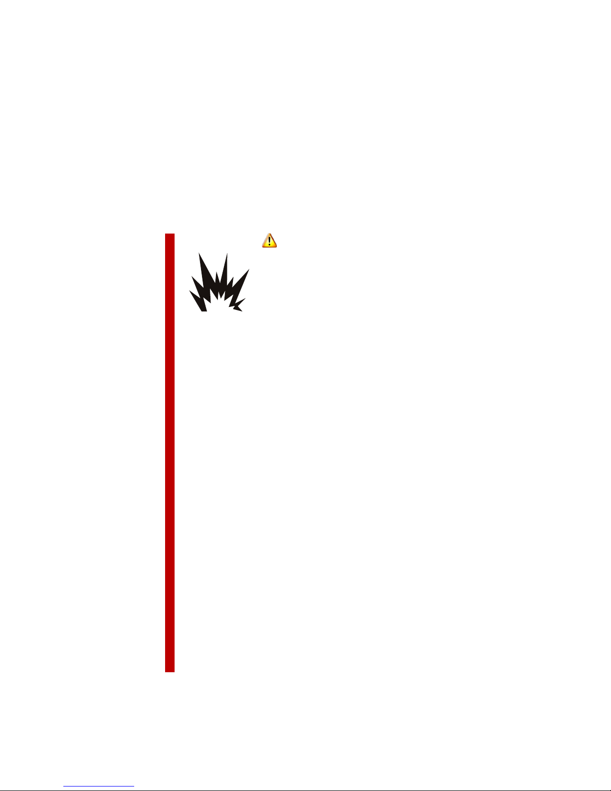
DANGER
Explosion hazard.
■ NEVER operate generator in an explosive
atmosphere or near combustible materials.
■ Keep generator, engine, fuel, and other
combustibles away from sparks, open flame,
and burning objects.
■ Do not smoke near engine.
■ Never use generator to jump-start a vehicle.
■ Before filling or draining fuel, stop engine and
allow it to cool.
■ Use correct fuel.
■ Replace fuel tank cap after refueling.
■ Do not mix lubricating oil with fuel.
■ Check oil level while filling and do not overfill.
■ For electric-start models:
❑ Lead acid batteries emit a colorless
explosive hydrogen gas. Keep batteries
away from sparks, open flame, and
burning objects.
❑ Do not smoke near batteries.
❑ Do not connect or disconnect battery
cables from the battery or engine while
the unit is cranking or operating.
Voltmaster Engine-Driven Generators 5
Page 12
Safety: Operating safety
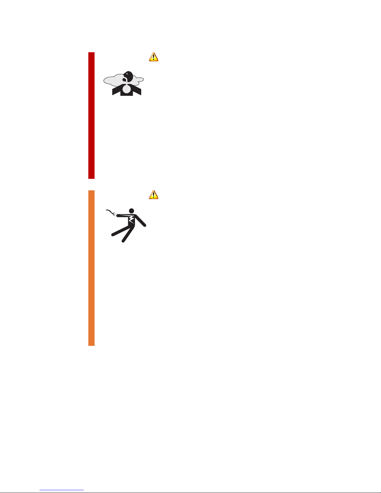
DANGER
Asphyxiation hazard.
Engine exhaust contains carbon monoxide, a
poison gas you cannot see or smell.
■ NEVER operate engine indoors, EVEN IF doors
and windows are open.
■ Operate the engine OUTSIDE, far away from
doors, windows, and vents.
■ Refill and drain fuel tank only in a well
ventilated area.
■ Perform maintenance in a well ventilated area.
WARNING
Shock hazard.
■ Use extreme caution when working on or with
electrical components.
■ Avoid contact with live terminals and
receptacles.
■ Ensure the generator is properly grounded in
accordance with all applicable electrical codes.
■ Do not operate generator in rain, snow, or wet
conditions.
■ Installation as a standby generator must
comply with all applicable electrical codes, and
requires a suitable power-transfer device to
isolate generator from power utility.
6 Voltmaster Engine-Driven Generators
Page 13
Safety: Operating safety
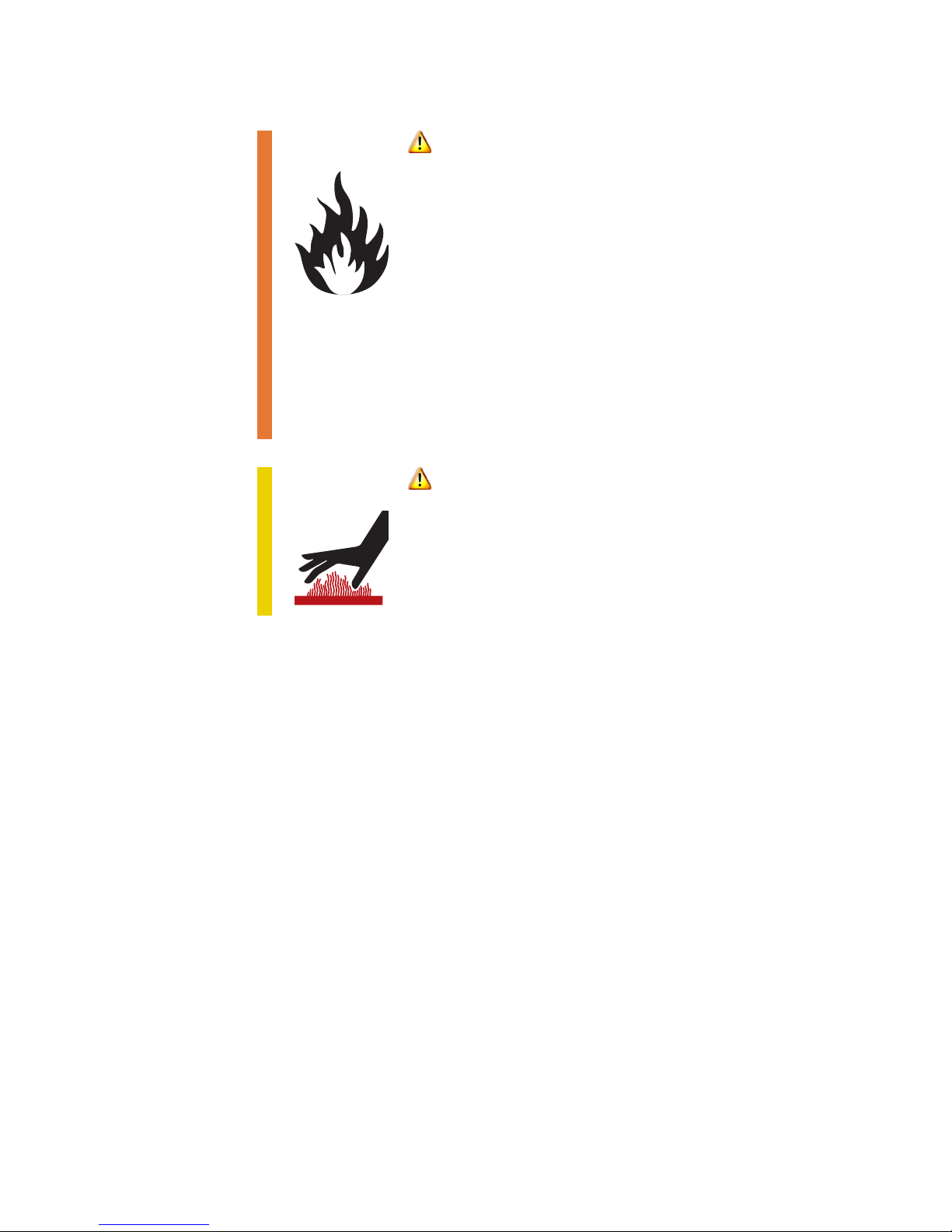
WARNING
Fire hazard.
■ Before transporting generator, drain fuel and
close fuel-shutoff valve.
■ A hot muffler can ignite flammable materials.
Keep area around muffler free of debris such as
leaves, paper, and cartons.
■ Remove all unnecessary grease and oil from
generator surfaces.
■ Do not leave any flammable material on
generator while it is running.
CAUTION
Risk of severe burn.
Do not touch engine, exhaust pipes, or any engine
component until cool.
■ Before using this equipment, carefully read, understand, and
observe all instructions in this manual and the engine manual.
■ Before using this equipment for the first time, visually inspect the
generator for loose or missing parts and damage that may have
occurred in shipment.
■ This equipment should not be operated by persons under 18 years
of age.
■ ALWAYS wear appropriate protective clothing, shoes, and other
protective devices, as required by the job.
■ ALWAYS wear appropriate respiratory, hearing, and eye protection.
■ NEVER operate this equipment when not feeling well due to fatigue,
illness, or medication.
Voltmaster Engine-Driven Generators 7
Page 14

Safety: Operating safety
■ NEVER operate this equipment under the influence or drugs or
alcohol.
■ When fueling electric-start engines, do not touch battery cables or
posts to gasoline supply can.
■ Before operating, know the location of the nearest fire extinguisher,
first aid kit, and emergency telephone.
■ Keep a fire extinguisher nearby and know its proper use.
Extinguishers rated ABC by the NFPA are appropriate for all
applications. For more information, consult your local fire
department.
■ Store fuel only in approved containers and in a well ventilated area.
Exhaust fumes are poisonous; do not inhale.
■ Be sure the generator is well ventilated on all four sides.
■ Do not operate this equipment in an enclosed area, such as a
recreational vehicle, marine vehicle, under the hood of a car or
truck, or inside a truck or van even with the windows and doors
open. All warranties are voided if the unit is operated in such an
area.
■ Keep generator and surrounding areas clean. Remove oily rags and
other material that could create a fire hazard.
■ NEVER use the generator with a cover over the unit. The generator
must operate in an open-air environment.
■ NEVER service generator or its components while generator is
running. Do not perform service or maintenance while generator is
hot.
■ When using generator for backup power, use a suitable powertransfer device to isolate generator from power utility. Failure to
isolate generator could cause serious injury or death.
■ Only a qualified technician should perform repairs on this
equipment, including the installation or replacement of parts and
accessories.
■ Use ONLY accessories or attachments that are recommended by the
manufacturer. Unauthorized equipment modifications will void all
warranties.
8 Voltmaster Engine-Driven Generators
Page 15

Safety: Engine safety
2.2 Engine safety
2.2.1 Operator safety
Before using the generator, refer to engine manufacturer’s
documentation for additional engine safety and operating
information.
2.2.2 California Proposition 65
WARNING
Health hazard.
Engine exhaust and some of its constituents are
known to the State of California to cause cancer,
birth defects, and other reproductive harm.
2.2.3 Spark arresters
IMPORTANT!
State and local safety codes specify that, in certain locations,
internal combustion engines that use hydrocarbon fuels must be
used with spark arresters.
A spark arrester is a device constructed of nonflammable materials
specifically for the purpose of removing and retaining carbon and
other flammable particles from the exhaust flow of an internal
combustion engine.
Spark arresters are qualified and rated by the United States Forest
Service. To comply with all applicable laws regarding spark
arresters, consult your local Health and Safety Administrator.
Voltmaster Engine-Driven Generators 9
Page 16
Safety: Maintenance and storage safety
2.3 Maintenance and storage
safety
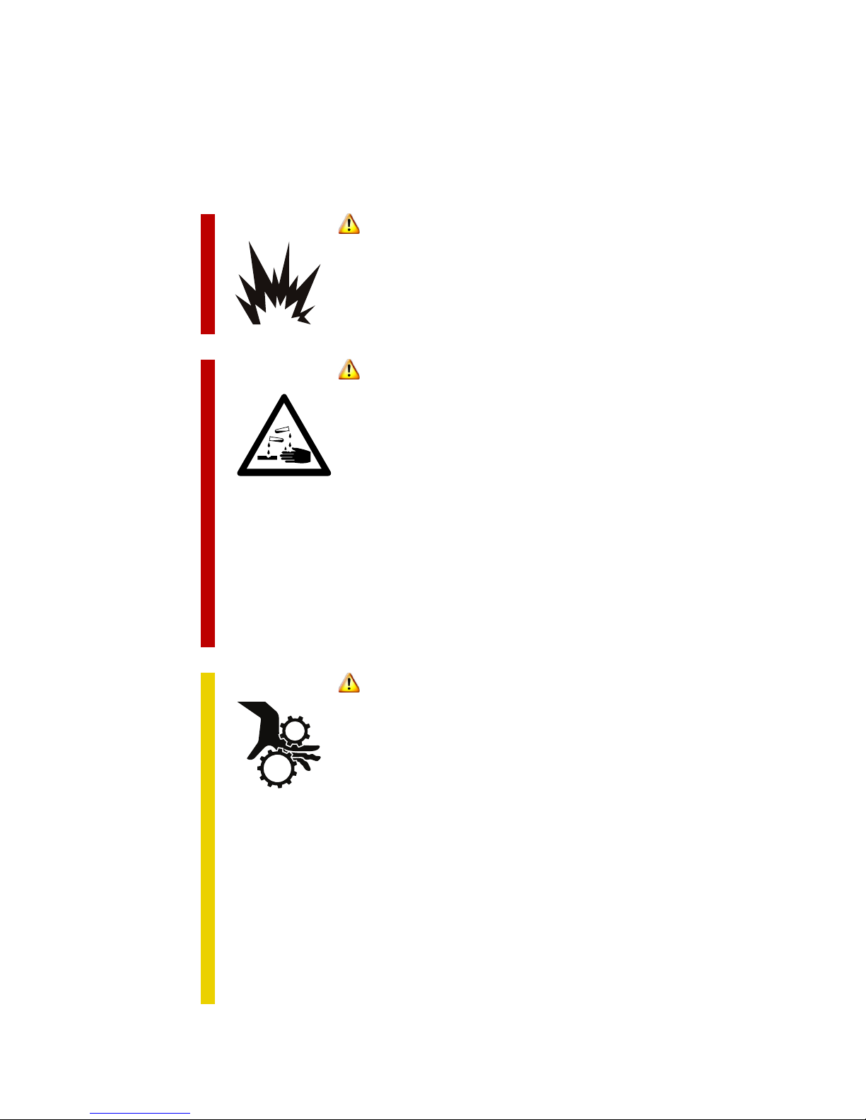
DANGER
Explosion hazard.
Do not use gasoline, other fuels, or flammable
solvents to clean parts.
DANGER
Corrosive material.
Battery acid will cause severe burns and
blindness.
■ Use extreme care when handling or servicing
batteries.
■ Never service batteries while generator is
operating.
■ Wear appropriate eye and hand protection.
■ Upon contact with skin or eyes, immediately
flush with water and seek medical help.
CAUTION
Moving parts can cause injury.
■ Prior to servicing, disconnect spark plug wire to
prevent accidental starting.
■ Prior to servicing electric-start models,
disconnect negative (–) cable from starter
battery, then disconnect the positive (+) cable.
■ Keep hands, hair, and tools away from moving
parts.
10 Voltmaster Engine-Driven Generators
■ Do not wear jewelry or loose fitting clothing
while performing maintenance.
■ Use extreme caution if making adjustments
while generator is operating.
Page 17

Safety: Maintenance and storage safety
■ Before servicing, ensure power cannot be started inadvertently
during service.
■ ALWAYS keep the generator in proper running condition.
■ ALWAYS fix damage to the generator immediately. Repair or replace
broken or worn parts. Only use parts from original manufacturer.
■ Replace operation and safety decals when they become difficult to
read.
■ When not in use, store equipment in a clean, dry location out of the
reach of children.
■ Before storing, drain fuel.
Voltmaster Engine-Driven Generators 11
Page 18

12 Voltmaster Engine-Driven Generators
Page 19

3 Operation
3.1 Before starting
3.1.1 Safety
Before operating the generator:
■ Read and be familiar with this instruction manual.
■ Read and follow all safety instructions (see Section 2, page 5).
■ Read and follow instructions in the engine manufacturer’s
documentation.
3.1.2 Fuel
■ For gasoline-powered models, use unleaded gasoline, 87 octane or
higher
■ For diesel-powered models:
❑ In normal ambient temperatures, use No. 2 diesel fuel (DF2)
❑ In cold weather, use No. 1 diesel fuel (DF1)
❑ JP5 or JP8 turbine fuel may be used with engine derations
Fuel additive
If left to stand in the engine for periods of more than 6 months,
gasoline will tend to form a varnish-like substance that will clog the
fuel system and the carburetor. The result will be a hard-to-start
engine. Check the engine manual or your local dealer for a
recommended gasoline additive that will prevent varnish
formation.
Fuel shutoff valve
If the generator is equipped with a fuel shutoff valve, the valve is
located under the fuel tank. When using the generator, be sure the
valve is open (turned counterclockwise) to permit the flow of fuel
from the tank. During transport, the valve must be closed.
Voltmaster Engine-Driven Generators 13
Page 20

Operation: Before starting
3.1.3 Oil
CAUTION
Crankcase pressure can blow hot engine oil out the fill tube,
causing severe burns.
■ Before removing oil cap, stop engine.
■ Loosen cap slowly and with great care.
CAUTION
Overfilling oil will damage diesel engine beyond repair.
■ Fill the oil sump to the full mark on the dipstick.
■ Check oil level while filling and DO NOT overfill.
■ If accidentally overfilled, drain extra oil.
To avoid engine damage, always check oil level and refill oil if
necessary before starting engine. DO NOT overfill oil.
Keep oil level between the minimum and maximum marks on the
dipstick. Engine damage caused by overfilling oil and low oil level
are not covered by the engine manufacturer’s warranty.
To avoid air bubbles pour oil slowly.
Low-oil shutdown
Most generator models are equipped with automatic low-oil
shutdown systems. Insufficient oil volume (on low-volume systems)
or pressure (on low-pressure systems) will cause the engine to stop.
For more information, see the engine manual.
Oil type
To select the proper oil:
■ For diesel engines, see the engine manual.
■ For all other engines, see Table 3.1 for oil grade.
■ For gasoline engines, use API Class SG or SH oil (also SG/CD, SG/CE,
SH/CD or SH/CE).
14 Voltmaster Engine-Driven Generators
Page 21
Operation: Before starting
Table 3.1 Recommended oil grade
Expected ambient temperature SAE viscosity grade
32°F (0°C) or higher 30
10 to 100°F (–12 to 38°C) 15W-40
0 to 80°F (–18 to 27°C) 10W-30 or 10W-40
–20 to 50°F (–28 to 10°C) 5W-30
Changing the oil
Change the engine oil as specified in the engine manual. Oil should
be drained while the engine is slightly warm.
3.1.4 Battery for electric-start models
For electric-start models, the starter battery is user-supplied. The
generator has space for the battery, and battery cables are included
with the generator.
DANGER
Explosion hazard.
When connecting battery cables, first connect the
positive (red) cable and then connect the negative
(green) cable.
Use only a 12-volt DC battery. Other battery requirements are listed
in Table 3.2.
Table 3.2 Battery type
Generator Battery
Gasoline-powered models,
except XCR180
Diesel-powered models and
XCR180 models
XAF alternative-fuel models 12VDC, Type U1 300 CCA, max. 5" width
12VDC, Type U1 300 CCA, max. 5" width
12VDC, 24BCI, 26BCI or 34/78, 400 CCA,
max. 6 7/8" width
Voltmaster Engine-Driven Generators 15
Page 22

Operation: Before starting
3.1.5 Location
Avoid placing the generator in locations where it will be exposed to
high humidity, dust, high ambient temperature, or corrosive fumes.
Moisture can condense on electrical components, causing
corrosion and short circuits. Accumulation of dirt on components
will retain moisture, accelerating wear on moving parts.
Provide at least 2 feet (61cm) of space on all sides of generator, for
ventilation and servicing. Ensure that the ventilator openings are
not obstructed.
Place the generator on a flat, level surface and ensure that it will not
shift or slide during use. Do not use the generator at an angle of
more than 15 degrees from horizontal.
3.1.6 Alternative fuels
Model XAF generators
XAF alternative-fuel-powered generators feature a special vapor
fuel carburetor with a vacuum safety shutdown and an electric
solenoid fuel shutdown.
XAF generators are derated, because the liquid propane (LP) and
natural gas (NG) fuel reduces engine output slightly versus gasoline.
Safety
■ Only a qualified LP or NG installer should work with LP and NG fuel
lines, connections, and components. Installing the fuel line for an
XAF generator is not a do-it-yourself job.
■ Propane gas is heavier than air and may settle in low places. Avoid
cutting, welding, and any activity that might ignite low-lying gas
near fuel lines or fuel tanks.
Fuel regulator
The regulator on the generator is a secondary regulator. Incoming
fuel supplies require an external, primary fuel regulator with output
of 11 inches of water column pressure. Fuel pressure that is too high
or too low will adversely affect generator performance.
Do not adjust the generator’s fuel regulator, which is preset at the
factory. To adjust the fuel mixture, see “Fuel mixture for Model XAF
generators” on page 24.
16 Voltmaster Engine-Driven Generators
Page 23

Operation: Before starting
Fuel shutoff valve
An external, manual fuel-shutoff valve is also required. The valve
must be installed using the flexible fuel line included with the
generator, which isolates the generator vibration from rigid
pipeline.
The shutoff valve must be installed within sight of the generator.
Fuel line
The incoming fuel line should be a 1-inch line. Fuel connections on
the generator are 3/4-inch NPT.
To protect the flexible fuel line against rupture, route the fuel line
away from the engine muffler and manifold. Do not remove the
cover from the solenoid valve until you are ready to make pipe
connections.
Before the flexible fuel connection is connected to the hard fuel
pipe connections, and after all other fuel line connections have
been made:
1. Ventilate the area.
2. Ensure there are no open flames, no smoking, no pilot lights and no
sparks.
3. While wearing eye protection, turn on the fuel line for about 5 to 10
seconds, to blow out any remaining pipe tape or pipe dope out of
the line. This will prevent debris from entering the generator’s fuel
regulator.
4. Check all connections for leaks with soap and water, and stop all
leaks before using the generator.
Voltmaster Engine-Driven Generators 17
Page 24

Operation: Before starting
3.1.7 Standby installations
WARNING
Shock hazard.
Failure to isolate generator from power utility
can result in death or serious injury.
When using the generator for backup power:
■ Never connect the generator output to any live
home or commercial electric circuits.
■ Use a suitable power-transfer device to isolate
the generator from the power utility.
■ Use a licensed electrician or electrical
contractor to install the power-transfer device.
If the generator will be connected to existing electric circuits during
a commercial power outage, the installation must provide a positive
means of isolating the commercial and generator power. The most
common means for isolation protection is to incorporate a suitably
rated double-throw, double-pole manual transfer switch.
The National Electrical Code, the state of California, many state and
local codes, and Canadian Hydro all require an isolation switch
between the generator and the utility line. Consult all applicable
national and your codes prior to installation.
A potential hazard exists during a power outage if the generator
output is connected to the dead home or commercial electric
circuits and no means is provided to isolate the electric circuits from
the commercial power source. A power utility lineman working to
return electric service to normal has every reason to believe that the
line is dead. If your electric circuits are not isolated, the generator
output will back feed to the power line and the lineman may be
electrocuted when he attempts repairs.
Furthermore, if the utility and generator are not isolated, and utility
power is restored while the generator is still powering the electric
circuits, severe damage to the generator will occur and the
possibility exists for an electrical fire.
Always employ a licensed electrician or electrical contractor to
install the power-isolation switch. This is not a do-it-yourself job.
18 Voltmaster Engine-Driven Generators
Page 25

Operation: Before starting
3.1.8 Preparing for use
1. Ensure the generator is in proper working order:
■ Check the generator for damage and wear.
■ Secure all fuel and wiring connections.
■ Tighten loose screws, nuts, and bolts.
■ If applicable, ensure the starter battery is fully charged (see
Section 3.3.3, page 28). If a trickle charger was used when the
generator was not in use, disconnect the charger.
2. Read tags and labels, and follow all directions. Remove hanging and
loose tags and labels; keep with generator for future reference.
3. Ensure oil drain plug is closed. Fill engine with the correct oil type as
specified in the engine manual.
4. Clean the generator before use. Do not allow dust, dirt, rain, or snow
to accumulate on the generator. Remove all oil deposits and other
foreign matter from the generator.
5. Ensure all air passages and cooling fins are free from foreign matter.
Use clean, dry compressed air at a maximum pressure of 25 psi
(172kPa) to blow dirt and dust out of cooling passages and control
cabinet.
6. For cold-weather starting, if possible, keep the generator in a warm
location until needed, then move it to the cold location and start it
immediately.
7. For Model XAF alternative-fuel generators, ensure the generator is
properly grounded.
3.1.9 After long-term storage
Before restarting the generator after it has been stored for 6 months
or longer:
1. Remove protective cover
2. Remove spark plug or plugs
3. Crank the engine slowly
4. Replace the spark plugs and tighten them
If the generator worked before being put into long-term storage
but no longer works, see the see the Voltmaster troubleshooting
manual, available at www.voltmaster.com.
Voltmaster Engine-Driven Generators 19
Page 26

Operation: Operating the generator
3.2 Operating the generator
3.2.1 Ground-fault protection
The generator features total ground-fault protection. When a
ground fault occurs on any receptacle:
■ The ground-fault circuit interrupter (GFCI) fault-sensing module
trips the generator’s main circuit breaker
■ Power to all receptacles is disengaged
■ A red LED on the control panel lights up, indicating a ground fault
If a ground fault occurs:
1. With the engine running, remove all loads.
2. Push the reset button on the GFCI fault-sensing module
3. Switch the main circuit breaker to the on position.
4. If the ground-fault condition continues with no load on the
generator, contact an authorized service center.
5. If the condition continues after putting a load on the generator:
a. Repeat steps 1 through 3.
b. Try a different load using any receptacle.
c. If the ground-fault condition does not reoccur, the problem is
likely with the equipment or cord that was connected when
the fault reoccurred.
d. If the ground-fault condition reoccurs, contact an authorized
service center.
Test the GFCI module at least once a month, and more regularly if
the generator is being used often, by starting the generator and
pushing the test button on the GFCI module. The test is successful if
the reset button pops with an audible “click” and the red LED
indicator lights up. To reset the generator after a successful test,
follow steps 1 through 3, above.
20 Voltmaster Engine-Driven Generators
Page 27

Operation: Operating the generator
3.2.2 Electrical loads
Ratings
Complete ratings for the generator are listed on the generator serial
number tag, which is attached to the generator housing.
Large power tools and large electric motors require additional
amperage for starting, as much as two to three times the ampere
rating listed on their nameplates.
NEVER increase the generator engine speed to get more output
from the generator. Engines operate at either 3600 RPM (for 60 Hz
models) and 3000 RPM (for 50 Hz models). Increasing the engine
speed could damage the generator and any equipment being
powered by the generator.
Do not exceed the ampere ratings on the outlet receptacles.
Overloading will damage the receptacles and could cause internal
damage to the generator.
Load requirements
■ Keep loads within the generator and receptacle ratings.
Overloading could damage the generator.
■ Loads should be applied gradually, not all at once.
■ Large electric motors should be started one at a time, beginning
with the largest motor, then the next largest, and so on.
■ When removing loads from the generator, voltage-sensitive items
such as televisions and computers should be removed first.
■ The generator is inherently self-regulating and its output
automatically adjusts to the load. Although diesel models have a
minimum load requirement (see “Model XDR diesel generators” on
page 22), other generators will not be damaged if operated with no
load.
Appendix A, page 33, provides information that can help in
determining your load requirements.
Voltmaster Engine-Driven Generators 21
Page 28

Operation: Operating the generator
Model XDR diesel generators
CAUTION
Operating a diesel generator without the proper load will
permanently damage the engine.
Always operate the diesel engine under load, using at least 25% of
its rated capacity.
Diesel generators require a load of at least 25% of the generator’s
rated output. Operating a diesel generator with insufficient load
(referred to as “wet stacking”) will irreparably damage the engine
and void the warranty.
Model XTP three-phase generators
When checking the no-load voltage on an XTP three-phase
generator, the voltage will be about 10% below the rating listed on
the generator serial number tag. When a load is placed on the
generator, the reactor transformer inside the generator activates,
and the voltage immediately increases to the generator’s rated
voltage.
If relays, electric controls, etc., are used with a three-phase motor, an
automatic voltage regulator is required. If an automatic voltage
regulator is installed, the voltage regulation is ±1.5%.
XTP generators feature a three-phase circuit breaker that is rated for
the amperage load of the generator. If the circuit breaker trips
under load, you must remove some of the load to prevent over
loading the generator. All three-phase circuit breakers are designed
for motor load starting, permitting momentary overload conditions
associated with three-phase motors.
Receptacles
The ratings on the generator serial number tag can be met by using
the receptacles in combination or individually, as long as the
generator and receptacle ampere ratings are not exceeded.
Receptacles are protected by ground-fault circuit interrupters
(GFCI). Consult the National Electrical Code, Underwriters
Laboratories or Canadian Standards Association code for groundfault protection requirements for temporary installations.
22 Voltmaster Engine-Driven Generators
Page 29

Operation: Operating the generator
Plugs and connected equipment
Use only 3-prong grounded plugs, 3-wire extension cords, and
3-wire or double-insulated power tools with the generator.
Full-power switch
Some models are equipped with a switch that allows selection of
120-volt power only or both 120- and 240-volt power.
■ When using the generator to power only 120-volt equipment, put
the full-power switch in the 120V position. In this position:
❑ The generator windings are connected in parallel
❑ The output of the generator is 120 volts
❑ The 240-volt receptacles are not functional
❑ The voltmeter indicates 120V
■ When using the generator to power 240-volt equipment, put the
power switch in the 120/240V position. In this position:
❑ Each 120-volt receptacle has half the power output of the
generator
❑ The 240-volt receptacles are functional
❑ The voltmeter indicates 240V
■ Before changing the switch position, remove all electrical loads
from the generator.
Idler
Some models are equipped with an idler switch. When the idler is
on, the engine will slow down when there is no electrical load on
the generator, improving fuel usage and generator life.
The generator should be started with the idler turned off. After the
engine has warmed up for 2 to 3 minutes, turn the idler on. If there
is no load on the generator, the engine speed will decrease. On
some models there will be a delay of 10 to 12 seconds before the
engine slows down.
With the idler turned on, when an electrical load is applied, the
engine speed will automatically return to normal and produce the
generator’s rated voltage.
For the idler to function, a battery must be connected to the engine.
Voltmaster Engine-Driven Generators 23
Page 30

Operation: Operating the generator
3.2.3 First-time use
Break-in period
Controlled break-in helps to ensure satisfactory service from the
generator.
Model XDR diesel generators
During the first 5 to 10 hours of operation, operate the generator
with electrical loads from 25 to 50 percent of the generator’s rated
capacity (indicated on the generator serial number tag). This will
ensure the valves are properly seated. After the first 10 hours of
operation, change the oil and oil filter.
Operating the diesel generator with insufficient load, referred to as
“wet stacking,” will damage the engine and void the warranty (see
“Model XDR diesel generators” on page 22).
All other models
During the first 2 to 3 hours of operation, do not apply heavy
electrical loads to the generator.
Change the oil after the first 3 hours of operation.
Fuel mixture for Model XAF generators
Before using an XAF alternative-fuel-powered generator for the first
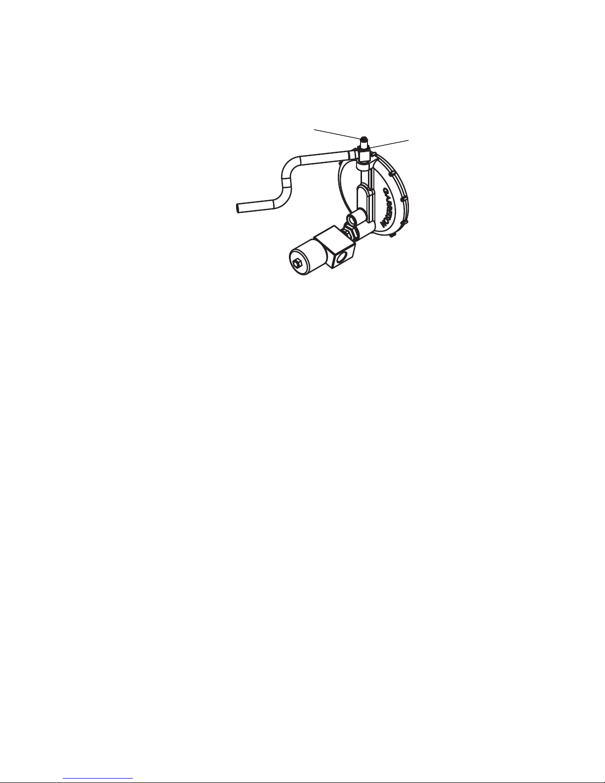
time, adjust the fuel mixture for proper engine performance. Refer
to Figure 3.1 and follow these steps:
1. Start the engine.
2. Set a multimeter to measure hertz (Hz) and insert its probes into
one of the generator’s 120VAC receptacles.
3. Loosen the fuel mixture nut.
4. Rotate the fuel mixture adjustment screw:
■ Counterclockwise for richer mixture (lower altitudes)
■ Clockwise for leaner mixture (higher altitudes)
5. Adjust the fuel mixture screw until the multimeter reads 60 Hz,
which ensures optimal generator performance at full speed and
maximum load.
6. After adjusting the fuel mixture, tighten the fuel mixture nut to lock
the adjustment screw in place.
24 Voltmaster Engine-Driven Generators
Page 31
Operation: Operating the generator
Fuel mixture adjustment
screw
Fuel mixture
nut
Figure 3.1 Fuel mixture adjustment screw
3.2.4 Starting the generator
Diesel recoil start
Some diesel generators feature electric-start engines with auxiliary
recoil starter. Before starting the engine on these models, if a
battery is not available, move the red or black lever near the fuel
pump to the up position. If a 12-volt battery is installed, the lever
must be in the down position at all times.
Air in fuel line
Air pockets in the fuel line will cause difficulty in starting and
operating the generator. Diesel generators are particularly
susceptible to air in the fuel line; Model XAF alternative-fuel
generators are not affected.
■ Before starting, pump the fuel lever 20 times or more.
■ Do not allow the generator to run out of fuel or to the bottom of the
fuel tank.
Voltmaster Engine-Driven Generators 25
Page 32

Operation: Operating the generator
Starting procedure
CAUTION
Load on generator at startup or shutdown can damage
equipment.
Remove all electric loads from the generator before starting or
stopping the engine.
1. Before operating the generator, follow all instructions in Section 3.1
and Section 3.1.9.
2. Start the generator:
a. Disconnect all loads.
b. For models with an idler switch, turn the idler off.
c. If the generator has a fuel shutoff valve (located under the fuel
tank), open the valve fully (turn it counterclockwise) to permit
the flow of fuel from the tank to the engine.
d. Adjust the carburetor choke as necessary.
■ Cold-starting requires full choke.
■ LP- and NG-powered generators do not require a choke for
starting.
■ Diesel-powered generators do not have a choke.
e. Start the engine using the electric starter or recoil cord,
referring to engine manufacturer’s instructions if necessary.
f. When the engine starts, close the choke.
g. For models with a ground-fault sensing module on the control
panel, ensure the green light on the panel is lit.
3. Apply loads:
a. Before connecting any load to the generator, run the engine
for 2 to 3 minutes, allowing it to reach normal operating
temperature.
b. Apply loads by inserting plugs into the proper receptacles and
turning on connected equipment.
c. See Section 3.2.2 for details about applying loads.
26 Voltmaster Engine-Driven Generators
Page 33

Operation: Operating the generator
3.2.5 Stopping the generator
Gradually remove all loads from the generator before stopping the
generator engine.
To stop the engine:
■ On models with an electric starter, rotate the key to the off position.
■ On all diesel models, you must keep pressure on the stop lever until
the engine comes to a complete stop.
■ On diesel generators with an electric-start engine and auxiliary
recoil starter, if the generator does not have a battery, move the red
or black lever near the fuel tank to the down position.
■ On other models, move the start/stop switch on the engine to the
stop position.
Always wait for the engine to come to a complete stop.
Runaway diesel engine
If the diesel engine does not stop when the start/stop switch is
moved to the stop position, the oil in the engine sump has been
overfilled and the engine is using over-pressurized sump oil as fuel.
To stop the engine with this condition you must block the air intake
flow until the engine stops.
If this situation has occurred, the air filter will be saturated with oil
and must be replaced before restarting the engine.
Voltmaster Engine-Driven Generators 27
Page 34

Operation: General maintenance
3.3 General maintenance
The generator should be run at least once a month for a few
minutes to keep all components in proper operating condition.
For engine maintenance requirements, see the engine manual.
For troubleshooting, see the Voltmaster troubleshooting manual,
available at www.voltmaster.com.
3.3.1 Gasoline-fueled generators
Model XCR, XSD, and XTP gasoline-fueled generators are EPA
certified and require the following maintenance.
■ The fuel cap includes a rubber gasket that can become worn over
time. The gasket is important for keeping the fuel system sealed,
and must be replaced if damaged. Check the gasket once a year.
Use only a gasket that provides a vapor-proof seal. Use only
manufacturer-approved replacement parts.
■ The EPA-approved fuel lines are made from rubber that can degrade
over time. The fuel lines are vital for proper operation, and must be
replaced if damaged. Check the fuel lines once a year. Use only EPAapproved fuel lines.
3.3.2 Model XAF alternative-fuel generators
When servicing an XAF generator, shut off all fuel lines and
eliminate all possible outside sources of ignition.
Only qualified personnel should service liquid propane and natural
gas generators.
3.3.3 Changing the oil
Change the engine oil as specified in the engine manual. Oil should
be drained while the engine is slightly warm.
28 Voltmaster Engine-Driven Generators
Page 35

Operation: General maintenance
3.3.4 Storage
Store the generator in a warm, dry location.
If the generator is used infrequently, the engine could become
difficult to start. For gasoline-powered generators, a fuel additive
can help prevent this situation from occurring. See “Fuel additive”
on page 13.
Before putting the generator into storage for 6 months or longer,
follow these steps:
1. Run the generator until it reaches normal operating temperature
(about 10 minutes) and then shut it down.
2. For gasoline-powered generators, drain the fuel from the carburetor
bowl.
3. While the engine is still warm, drain the oil from the engine base,
then fill with fresh oil.
4. For gasoline-powered generators, remove the spark plug or plugs,
pour 1 ounce of engine oil into the cylinder or cylinders, crank the
engine slowly, and replace but do not tighten the spark plugs.
5. Service the air cleaner.
6. Plug the exhaust outlet to prevent moisture, bugs, and dirt from
entering.
7. Clean off dirt and grease.
8. Put a cover over the unit and store to avoid extreme heat or cold.
Voltmaster Engine-Driven Generators 29
Page 36
Operation: General maintenance
3.3.5 Battery
For generator models that have a battery, regular maintenance is
necessary for the battery to function properly and for long battery
life.
Safety
Explosive gases can cause blindness and severe
injury.
When working on or near batteries:
■ Wear eye protection.
■ Prevent sparks and open flames.
■ No smoking anywhere in the vicinity.
DANGER
■ Keep children clear of the area.
DANGER
Sulfuric acid can cause blindness and severe
burns.
■ Use caution when working on or near batteries.
■ Never service batteries while generator is
operating.
■ Do not tilt generator or batteries.
■ Avoid contact with skin, face, and eyes.
■ Wear appropriate eye and hand protection.
■ Upon contact with skin or eyes, immediately
flush with water and seek medical help.
■ Keep batteries out of reach of children.
30 Voltmaster Engine-Driven Generators
Page 37

Operation: General maintenance
■ Even when batteries are not in operation, self-discharge generates
hydrogen gas that can explode. Always store and work on batteries
in a well ventilated area.
■ Always wear proper eye, face, and hand protection when working
on or near batteries. Battery acid will cause severe eye damage and
skin burns. If contact with battery acid occurs, immediately flush
with water and seek medical help.
■ Keep all sparks, flames, and cigarettes away from batteries at all
times.
■ Never lean over batteries when testing or charging.
■ Keep battery vent caps tight and level, except when watering
batteries.
■ Avoid tilting the generator with a battery installed.
■ To prevent short circuits and sparks, exercise caution when working
with metallic tools or conductors near batteries.
■ To reduce the risk of sparks, ensure connectors make good contact
with battery terminals. Replace cables that appear suspicious or
have visible cracks or bare wires.
■ NEVER connect or disconnect battery cables from batteries or the
generator while the engine is cranking or operating.
■ ALWAYS ensure battery connections are the correct polarity. The red
cable is positive (+) and the green cable is negative (–).
■ Keep battery terminals clean and terminal connections tight.
■ After making connections at the battery terminals, coat the
terminals with a light application of petroleum jelly or grease to
retard corrosion.
Voltmaster Engine-Driven Generators 31
Page 38

Operation: General maintenance
Charging
■ Observe battery safety precautions (see “Safety” on page 30).
■ To lengthen battery life and to prevent freezing, always keep
batteries fully charged.
■ The charging circuit is operational during engine cranking and
running. The charging circuit is not designed to recharge a dead
battery but only to maintain the charge in the battery. If the
generator is not in regular, daily use, check battery voltage once a
week.
■ Charge the battery and keep it fully charged if any of the following
conditions exist:
❑ If the generator will be run infrequently
❑ If the battery will be stored for a long period of time
❑ If the battery will be located in an unheated room
Cleaning
■ Observe battery safety precautions (see “Safety” on page 30).
■ Keep batteries clean and dry, avoiding accumulation of dust, dirt,
grime, and moisture.
■ To clean batteries, use a solution of 50% baking soda and 50%
water. Do not allow cleaning solution or other material to enter
battery cells. Rinse batteries with clean water and allow to dry
thoroughly.
■ At least once a year, visually inspect terminals and cables for signs of
corrosion, especially in hot temperatures.
32 Voltmaster Engine-Driven Generators
Page 39

Appendix A
Volts Amps× Watts=
Power requirements
The information provided in this appendix is for reference only.
Values presented here are not necessarily representative of all such
equipment.
A.1 Sizing the generator
In most applications, the generator will provide power to devices
that use a total wattage rating up to the rated wattage output of the
generator. For example, to power ten 100 watt light bulbs, the
generator rated wattage output would need to be 1000 watts
(10 × 100 = 1000).
In order to operate an appliance that has an electric motor, such as a
compressor, pump, freezer, saw, or drill, you must calculate the
wattage required to start the appliance motor. The rule of thumb is
to multiply the wattage requirement by three. For example, to run a
drill with a rated wattage requirement of 300 watts, the wattage
requirement to start the electric motor would be 900 watts
(300 × 3 = 900).
■ To calculate wattage, use the formula in Figure A-1.
■ For the approximate starting wattage for appliances with motors,
see Table A-1.
■ When using extension cords, refer to Table A-2.
■ For approximate equipment power requirements, see Table A-3.
Figure A-1 Formula for calculating wattage
Voltmaster Engine-Driven Generators 33
Page 40

Power requirements: Sizing the generator
Table A-1 Approximate current requirements for electric motors
Horsepower Running watts Starting watts
Universal
motor*
1/6 275 400 600 850 1200
1/4 400 500 850 1050 1700
1/3 450 600 950 1350 1950
1/2 600 750 1300 1800 2600
3/4 850 1000 1900 2600 —
1 1000 1250 2300 3000 —
1 1/2 1600 1750 3200 4200 —
2 2000 2350 3900 5100 —
3 3000 — 5200 6800 —
5 4800 — 7500 9800 —
*Small appliance
NOTE: For pumps, air compressors, air conditioners, and inverters, add at least 25% to starting wattage.
Induction
motor
Capacitor
motor
Split-phase
motor
34 Voltmaster Engine-Driven Generators
Page 41

Power requirements: Sizing the generator
Table A-2 Minimum extension cord gauge
Continuous load
Minimum gauge
Amps Watts
@ 120 volts @ 240 volts
2 240 480 22 20 18
3 360 720 22 18 16
4 480 960 20 16 16
5 600 1200 18 16 14
6 720 1440 18 16 14
8 960 1920 16 14 12
10 1200 2400 16 12 12
12 1440 2880 16 12 10
14 1680 3360 14 12 10
16 1920 3840 14 10 10
18 2160 4320 14 10 8
20 2400 4800 12 10 8
22 2640 5280 12 10 8
25 3000 6000 12 10 6
30 3600 7200 10 8 6
35 4200 8400 10 8 4
40 4800 9600 8 6 2
50 6000 12,000 6 4 2
60 7200 14,400 4 2 —
0–50 foot
length
50–100 foot
length
100–150 foot
length
Voltmaster Engine-Driven Generators 35
Page 42

Power requirements: Sizing the generator
Table A-3 Approximate equipment power requirements*
Household and RV equipment Running watts Starting watts
Central air conditioner 10,000 BTU 1500 2200
Clothes dryer, electric 5200 5750
Clothes dryer, gas 700 1800
Clothes washing machine 1150 2300
Coffee maker 1750 —
Computer, desktop 600–800 —
Computer, laptop 200–250 —
Computer monitor 200–250 —
Computer printer 400–600 —
Dishwasher, cool dry 700 1400
Dishwasher, hot dry 1450 1400
Frying pan, electric 1300 —
Furnace fan, gas or oil 1/8 HP 300 500
1/6 HP 500 750
1/4 HP 600 1000
1/3 HP 700 1400
1/2 HP 875 2350
Hair dryer 300–1200 —
Iron 1200 —
Lights bulb wattage bulb wattage —
Microwave oven 650 watts 1000 1000
1000 watts 1500 1500
Radio 50–200 —
Refrigerator or freezer 700 2200
RV air conditioner 7,000 BTU 600 1700
10,000 BTU 700 2000
13,500 BTU 1250 2750
15,000 BTU 1500 3500
Stove, electric 6-inch element 1500 —
8-inch element 2100 —
Sump pump 1/3 HP 800 1300
1/2 HP 1050 2150
Television 300 —
Toaster, 2-slice 1050 —
Toaster, 4-slice 1650 —
Well pump 1/2 HP 1000 2100
Vacuum cleaner 800–1100 —
36 Voltmaster Engine-Driven Generators
Page 43

Power requirements: Sizing the generator
Table A-3 Approximate equipment power requirements* (continued)
Contractor equipment Running watts Starting watts
Air compressor (see Table A-1) 1/2 HP 975 1600
1 HP 1600 4500
1 1/2 HP 2200 6000
2 HP 2800 7700
Bench grinder 8 inch 1400 2500
Circular saw 6 inch 950 2200
7 1/4 inch 1200 2600
8 1/2 inch 1500 3000
10 inch 2000 3900
Drill 1/4 inch 300 400
3/8 inch 475 650
1/2 inch 750 900
1 inch 1000 1250
Impact wrench 1/2 inch 600 750
3/4 inch 750 900
1 inch 1200 1400
Jig saw 300 400
Miter saw 10 amp 1100 2000
15 amp 1650 3000
Mixer 3 1/2 cubic ft. 1000 2300
Pressure washer 5/8 HP 900 2700
1 HP 1200 3600
Reciprocating saw, heavy-duty 750 1400
Sander, belt, disc or orbital 1200 2600
Table saw 10 inch 1800 4500
Water pump, non-submersible 3000 gph 600 2250
5000 gph 750 2850
10,000 gph 1100 4100
15,000 gph 1600 5250
Water pump, submersible 3000 gph 500 1750
5000 gph 650 2500
10,000 gph 1000 3750
15,000 gph 1500 5000
Welder, electric 70 amp AC 2800 —
200 amp AC 9000 —
230 amp AC @100 amps 7800 —
250 amp AC/DC @75 amps 9800 —
Voltmaster Engine-Driven Generators 37
Page 44

Power requirements: Sizing the generator
Table A-3 Approximate equipment power requirements* (continued)
Farm equipment Running watts Starting watts
Battery charger 4 amp 90 —
15 amp 380 —
60 amp with 240-amp boost
100 amp with 300-amp boost
Electric fence
Grain cleaner 1/4 HP 650 1000
Grain conveyor, portable 1/2 HP 1000 2400
Heater, portable liquid-fuel type 50,000 BTU 400 675
Heater, portable radiant type 1300 —
Milk cooler 1100 1800
Milker (vacuum pump)
Stock tank de-icer 1000 —
25 mile
100,000 BTU 500 1260
150,000 BTU 625 1875
2 HP
1500/5750 —
2400/7800 —
250 —
1000 2300
*The power requirements listed here are estimates. To determine actual wattage for the items
you wish to power, refer to owner’s manuals or the data plate on the equipment.
38 Voltmaster Engine-Driven Generators
Page 45

Page 46

Voltmaster is a Wanco brand. Voltmaster, Wanco, and the Voltmaster and Wanco
logos are registered trademarks of Wanco Inc. All other trademarks are property
of their respective owners.
WANCO INC.
5870 Tennyson Street
Arvada, Colorado 80003
800-730-3927
303-427-5700
303-427-5725 fax
www.voltmaster.com
©2012 Wanco Inc. All rights reserved. Printed in the USA. | 207071 Rev. A
 Loading...