

Page 1
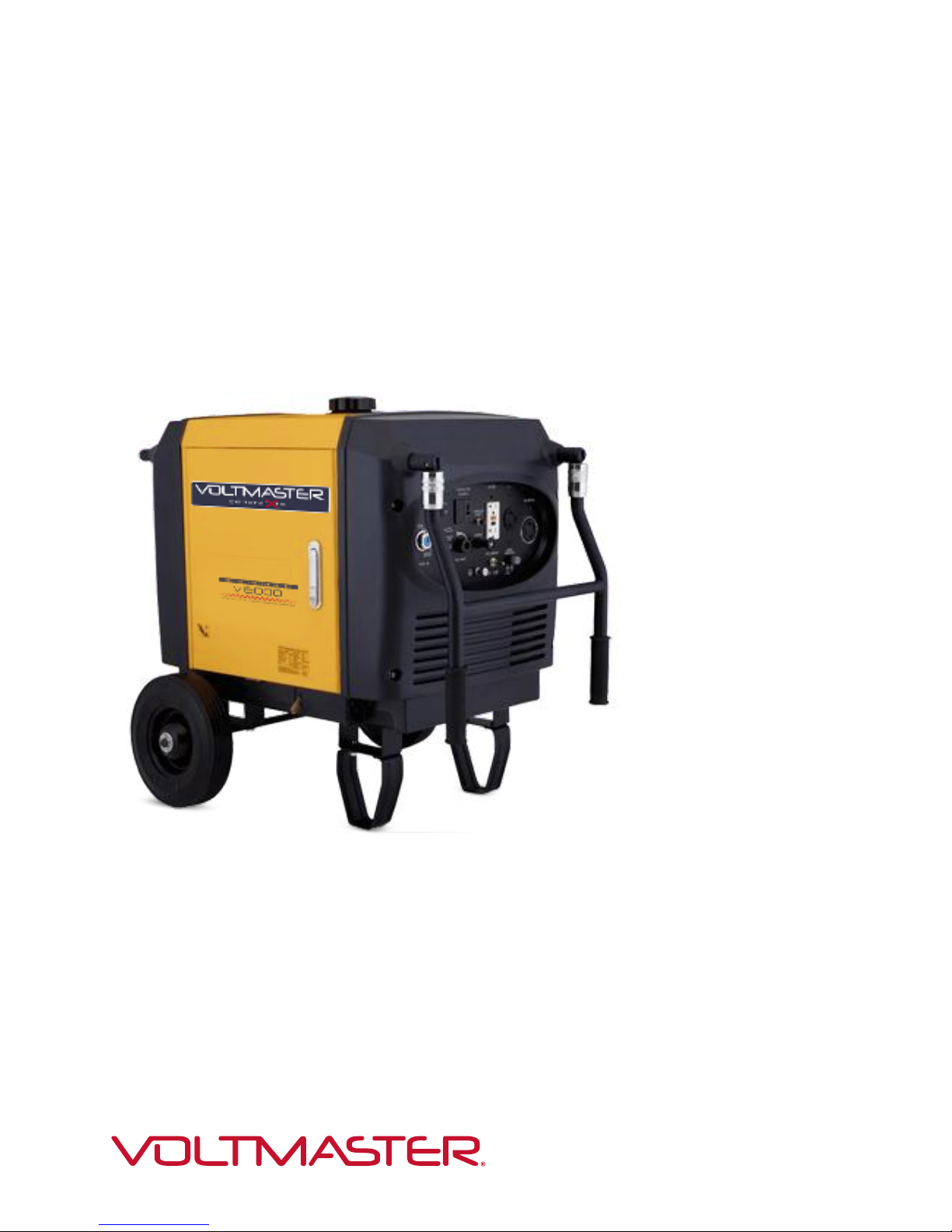
Model VI6000
Digital Inverter Generator
User’s Manual
January 2015
Page 2

PREFACE
Thank you for purchasing a Voltmaster® inverter generator.
This manual covers the operation and preventive maintenance of the VI6000
generator with EPA and California Air Resources Board (CARB) certification if so
designated.
All information in this publication is based on the latest product information available at the
time of printing.
We reserve the right to make changes at any time without notice and without incurring any
obligation.
No part of this publication may be reproduced without written permission.
This manual should be considered a permanent part of the generator and should remain
with it if it is resold.
Pay special attention to statements preceded by the following words:
Failure to properly follow these precautions can result in property
damage, serious injury or DEATH!
Read all labels and t
enerators produce carbon monoxide, a poisonous, colorless, odorless gas that can
door use of a generator can kill quickly. Generators should be used outdoors only.
enerators should be used outdoors only and away from garages and open windows and
he owner's manual before operating this generator.
G
cause death or serious injury.
In
G
protected from rain and snow.
Page 3

Always stop engine before refueling. Wait 5 minutes before restarting.
he portable generator is not meant to be used as a permanent back-up power system for
Indicates a strong possibility of severe personal injury or death if
Indicates a possibility of personal injury or equipment damage if
NOTE Gives helpf
a problem any questions about the generator, consult an
Our generators are designed to give safe and dependable service if
Keep any source of ignition away from the fuel tank at all times.
T
the home. A permanently installed stationary generator is designed to be safely used for
this specific purpose.
instructions are not followed.
instructions are not followed.
ul information.
If should arise, or if you have
authorized dealer or service center.
operated according to the instructions. Read and understand the
Owner's Manual before operating the generator. Failure to do so
could result in personal injury or equipment damage.
- 2 -
Page 4

CONTENTS
REFACE ...................................................................................................................................... 1
TENTS ................................................................................................................................... 3
. SAFETY INSTRUCTIONS ......................................................................................................... 5
. COMPONENT LOCATIONS ...................................................................................................... 8
. PRE OPERATION CHECK ...................................................................................................... 13
ARTING THE GENERATOR .............................................................................................. 16
. GENERATOR USE ................................................................................................................. 19
. STOPPING THE GENERATOR ............................................................................................. 27
. MAINTENANCE ..................................................................................................................... 28
P
CON
1
2
2.1 Exterior View ........................................................................................................................ 8
2.2 Inlet System .......................................................................................................................... 9
2.3 Exhaust System .................................................................................................................... 9
2.4 CARB Evaporative Control System .................................................................................... 10
2.5 Carbon Canister .................................................................................................................. 11
2.6 Control Panel ...................................................................................................................... 12
2.7 Serial Number ..................................................................................................................... 12
3
3.1 Engine Oil Level ................................................................................................................. 13
3.2 Fuel Level ........................................................................................................................... 14
3.3 Air Cleaner .......................................................................................................................... 15
4. ST
5
5.1 AC Power Application ......................................................................................................... 21
5.2 Output and Overload Indicators .......................................................................................... 22
5.3 Voltage Selection Switch .................................................................................................... 23
5.4 Smart Throttle ..................................................................................................................... 24
5.5 Air Conditioning Operation .................................................................................................. 24
5.6 DC Power Application ......................................................................................................... 25
6
7
7.1 Emission Control System ................................................................................................... 28
7.2 Maintenance Schedule ....................................................................................................... 31
7.3 Changing The Oil ................................................................................................................ 31
7.4 Air Cleaner Service ............................................................................................................. 32
7.5 Spark Plug Service ............................................................................................................. 33
7.6 Spark Arrestor Maintenance .............................................................................................. 35
- 3 -
Page 5

8. TRANSPORTING/STORAGE ................................................................................................. 36
OOTING ........................................................................................................... 37
PECIFICATIONS ................................................................................................................ 39
IRING DIAGRAM ................................................................................................................ 40
HEEL KIT .......................................................................................................................... 41
9. TROUBLESH
10. S
11. W
12. W
- 4 -
Page 6

1. SAFETY INSTRUCTIONS
■ Our generators are designed to give safe and
dependable service if operated according to these
instructions.
Read and understand the owner's manual before
operating the generator. Failure to do so could result in
personal injury or equipment damage.
■Exhaust gas contains poisonous carbon monoxide.
Never run the generator in an enclosed area.
Be sure to provide adequate ventilation.
The muffler becomes very hot during operation and
remains hot for several minutes after stopping the
engine.
Be careful not to touch the muffler while it is hot.
Let the engine cool before storing the generator indoors.
The engine exhaust system will be heated during
operation and remain hot immediately after stopping the
engine.
To prevent burns, pay attention to the warning marks
attached to the generator.
The generator must be operated outside with
adequate ventilation.
It cannot be operated in an enclosed compartment of any
vehicle or garage area.
- 5 -
Page 7

To ensure safe operation:
■Gasoline is extremely flammable and explosive under
certain conditions. Refuel in a well ventilated area with
the engine stopped.
■Keep away from smoking materials, sparks and other
sources of combustion when refueling the generator.
Always refuel in a well-ventilated location.
■Wipe up spilled gasoline at once.
■Restrict use of the generator in high-hazard risk areas.
■Connections for standby power to a building's electrical
system must be made by a qualified electrician and must
comply with all applicable laws and electrical codes.
Improper connections can allow electrical current from
the generator to back feed into the utility lines. Such
back feed may electrocute utility company workers or
others who contact the lines during a power outage, and
when utility power is restored, the generator may
explode, burn, or cause fires in the building's electrical
system. This generator is not designed to be connected
to an automatic transfer switch. Serious damage to the
engine and inverter module may result.
■ Always make a pre-operation inspection before you
start the engine.
■Place the generator at least three feet or one meter away
from buildings or other equipment during operation.
■Operate the generator on a level surface to prevent fuel
spillage or oil starvation.
■Know how to stop the generator quickly and understand
operation of all the controls. Never permit anyone to
operate the generator without proper instructions. Keep
children and pets away from the generator when it is in
operation.
- 6 -
Page 8

■Never operate the generator with the door open or any
panels removed. Do not operate in any enclosure such
as an RV compartment.
■Keep away from rotating parts while the generator is
running.
■The generator is a potential source of electrical shocks
when misused; do not operate with wet hands.
■Do not operate the generator in rain or snow or let it get
wet.
- 7 -
Page 9
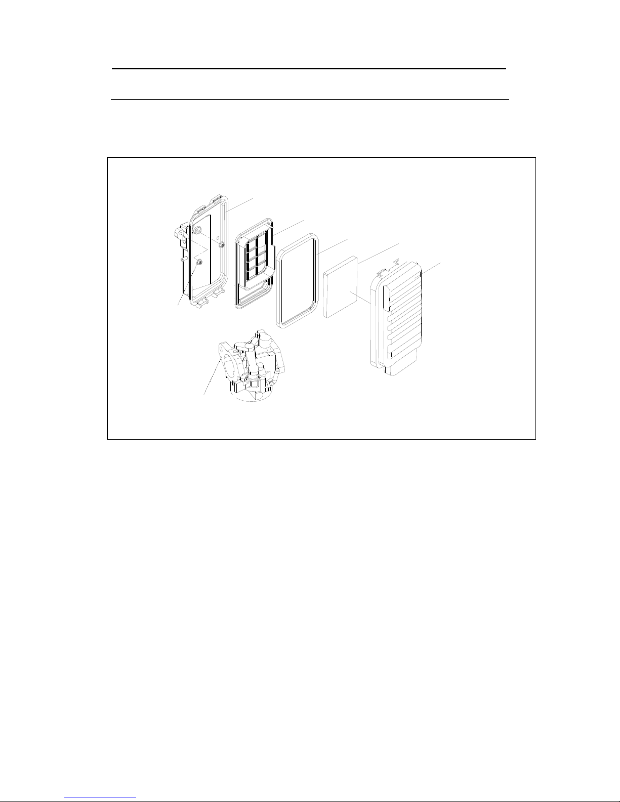
2.2 Inlet System
空气滤清器底壳
Air filter shell
滤芯固定
密封垫
滤芯
空气滤清器盖
螺母
化油器部件
架
Filter element
Air filter cover
Carburetor
Nut
Seal gaske
Fixed bracket
t
2. COMPONENT LOCATIONS
- -
Page 10
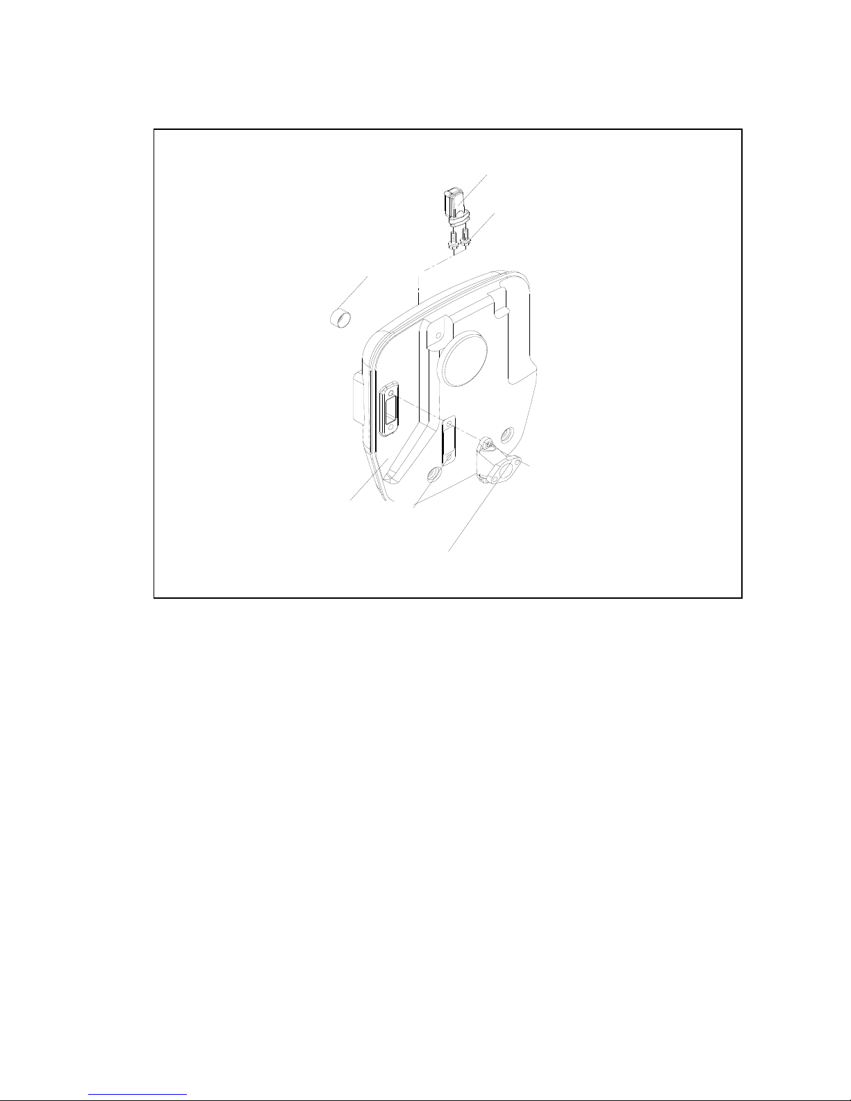
2.3 Exhaust Systemhaust System
二次补气阀组件
螺栓
防火帽组件
消声器本体总成
排气管
垫片A
Secondary air injection valve
Bolt
Spark Arrestor
Muffler assembly
Exhaust pipe
Muffler••
Gasket A
- 9 -
Page 11
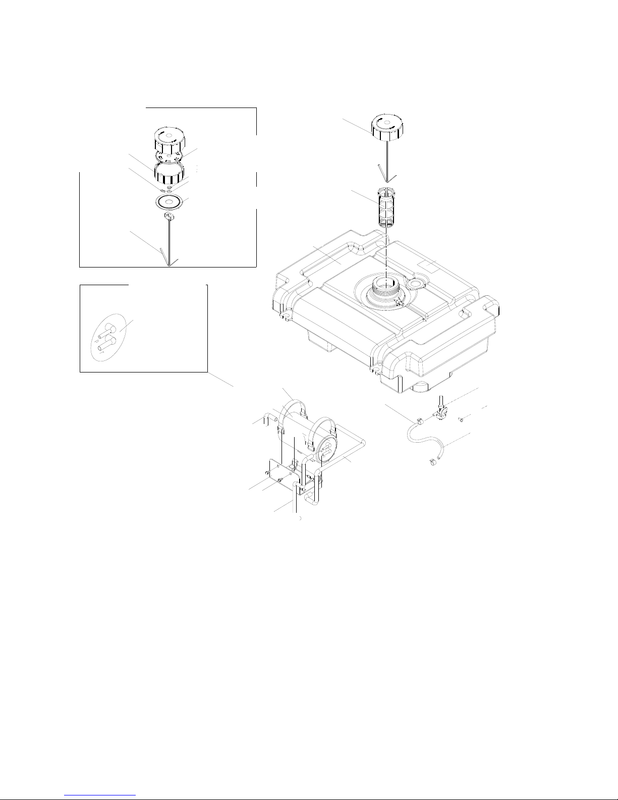
2.4 CARB Evaporative Control System
油箱盖总成
加油口过滤网
油箱
油开关组件
输油管
螺钉
C-U-05-012
Q-08-006
油箱盖
油 棘爪箱盖内
油箱盖内螺纹套
垫圈
开口销
油箱盖内垫片
防掉倒钩
油箱盖内称套
证书编号
材 号
管
碳罐
)
碳 皮带
料和证书编
油箱通气
碳罐负压管
(接空滤)
固定架焊合
螺栓
大气弯管
碳罐(650cc
罐固定
X6800BM
C-U-07-016
证书编号
bracket
Carbon canister (650cc)
Curved hose
Certificate No.
C-U-07-016
Hook
Fuel tank
Pallet
Filter screen Washer
Gasket
Bushing
Fuel tank cover
Threaded sleeve
Cotter pin
Fuel cap
Certificate No.
X6800BM
Q-08-006
Screw
Certificate No.
C-U-05-012
Fuel switch
Fuel hose
Vent hose
Connected to air filter
Bolt
Fixed frame
- 10 -
Page 12
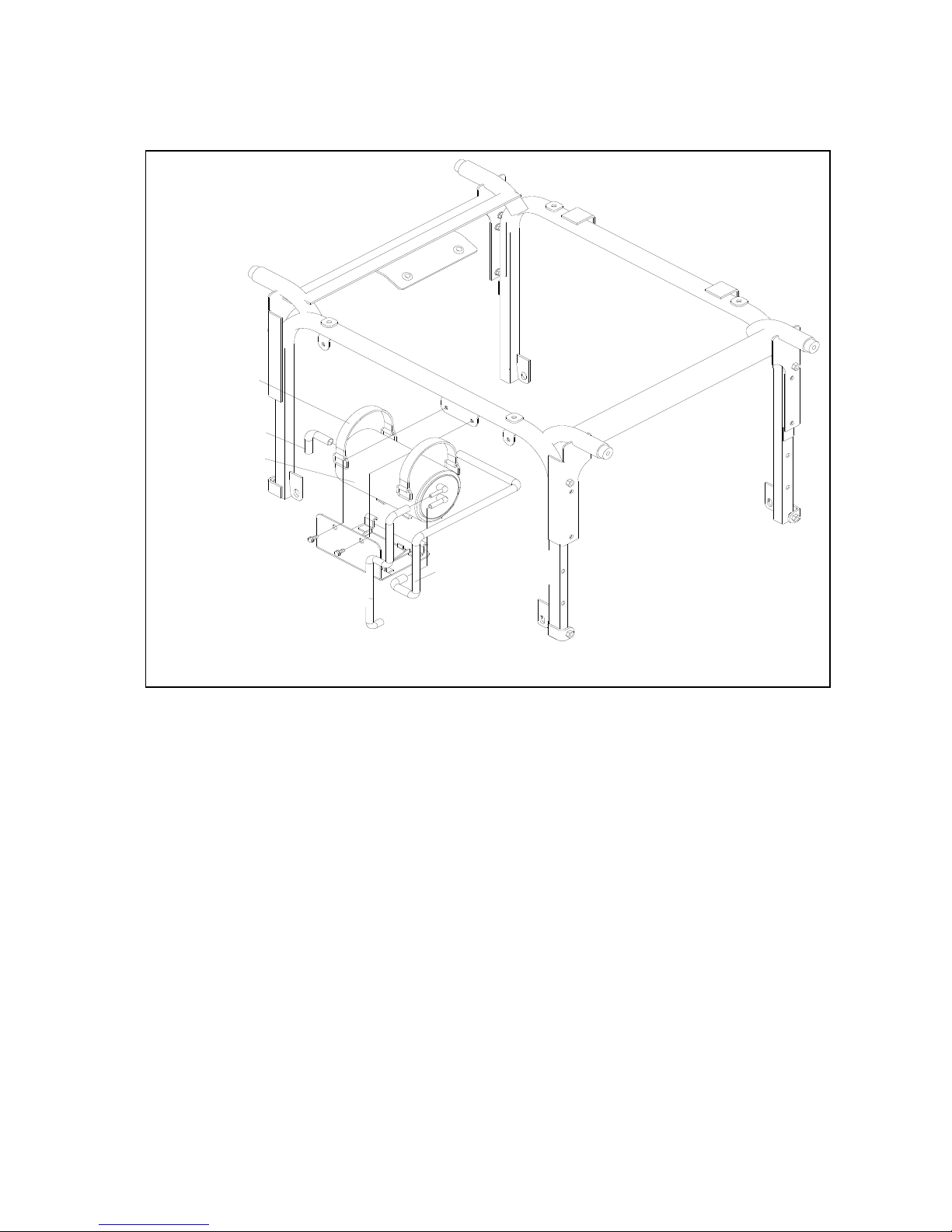
2.5 Carbon Canister Location (CARB only)
大气弯管
碳罐固定皮带
碳罐
碳罐负压管
Bracket
Curved hose
Carbon
Canister
油箱通气管
Vent hose
- 11 -
Page 13
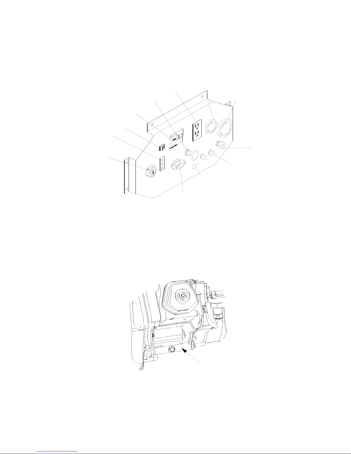
2.6 Control Panel
2.7 Serial Number
The engine serial number is stamped on the engine block to the left of the oil drain plug. In
most cases the battery will have to be removed to view it clearly. Refer to this number
when ordering parts or making technical inquiries.
直流插座
发动机开关
接地端
燃油开关
指示灯
智能节气门
阻风门手柄
电压选择开关
过载保护器
交流插座
交流插座
交流插座
120V 30A Receptacle
Ground Terminal
Overload Reset Switch
Voltage Selection Switch
Fuel Switch
Engine Switch
Indicator
DC Receptacle
GFCI Receptacle
120/240V 30A Receptacle
Smart Throttle
Choke Handle
- 12 -
Page 14
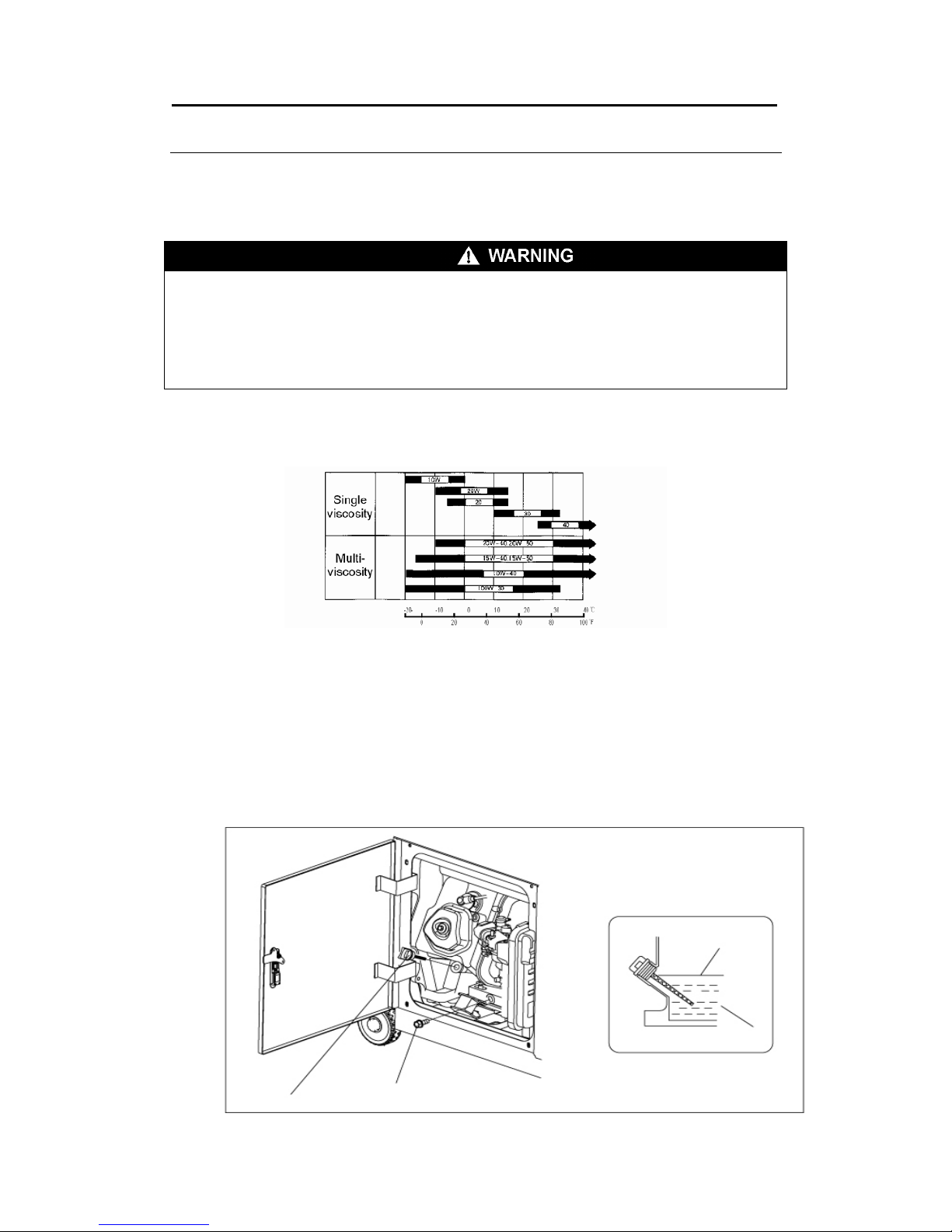
3. PRE-OPERATION CHECK
Be sure to check the generator on a level surface with the engine stopped.
3.1 Check the engine oil level
WARNING
■ Using non detergent or 2-stroke eng shorten the engine's service life.
eed
ine oil could
■ Use a high-detergent, premium quality four cycle engine oil, certified to meet or exc
U.S. Automobile manufacturer's requirements for API Service Classification SG/SF.
■ Select the appropriate viscosity for the average temperature in your area.
SAE Viscosity Grades
pen t
Ambient Temperature
door. Remove the oil filler cap and wipe the dipsO he service tick with a clean rag.
il Check the oil level by inserting the dipstick in the filler hole without screwing it in. If the o
level is below the end of the dipstick, refill with recommended oil up to the top of the oil
filler neck.
Dipstick
Oil drain bolt
Upper limit
Lower limit
- 13 -
Page 15
■Running the engine with insufficient oil can cause serious engine damage.
ls below the ■The oil Alert System will automatically stop the engine before the oil level fal
safe limit. However, to avoid the inconvenience of an unexpected shutdown, it is still
advisable to visually inspect the oil level before each use.
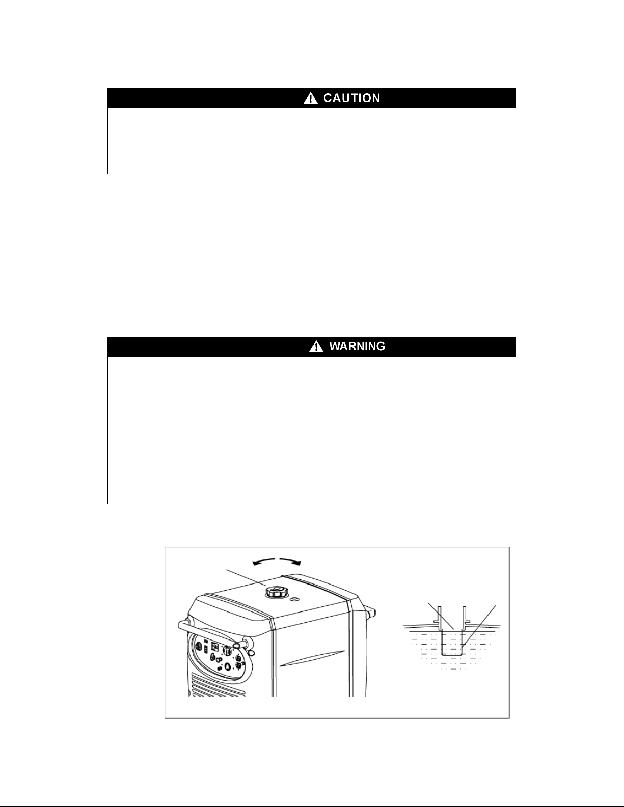
3.2 Check the fuel level
lar gasoline Do not use premium or high octane fuels.
nce
f the fuel strainer.
.
Use unleaded 87 octane regu
The engine is tuned to run on regular gasoline and engine damage and poor performa
may result from using higher octane fuels.
If the fuel level is low, refill to the shoulder o
Never use an oil/gasoline mixture or dirty gasoline.
Avoid getting dirt, dust or water in the fuel tank.
After refueling, tighten the fuel filler cap securely
■Gasoline is extremely flammable and under certain conditions.
ow flame or
ter refueling,
l vapor may ignite. If any fuel
f vapors. KEEP OUT OF
is explosive
■Refuel in a well-ventilated area with the engine stopped. Do not smoke or all
sparks in the area where the engine is refueled or where gasoline is stored.
■Do not overfill the fuel tank (there should be no fuel in the filler neck). Af
make sure the fuel filler cap is closed properly and securely.
■Be careful not to spill fuel when refueling. Spilled fuel or fue
is spilled, make sure the area is dry before starting the engine.
■Avoid repeated or prolonged contact with skin or breathing o
REACH OF CHILDREN.
Fuel tank capacity: 5.8 gallons or 22 liters
Fuel filler cap
Loosen
Tighten
Fuel surface
Strainer
- 14 -
Page 16
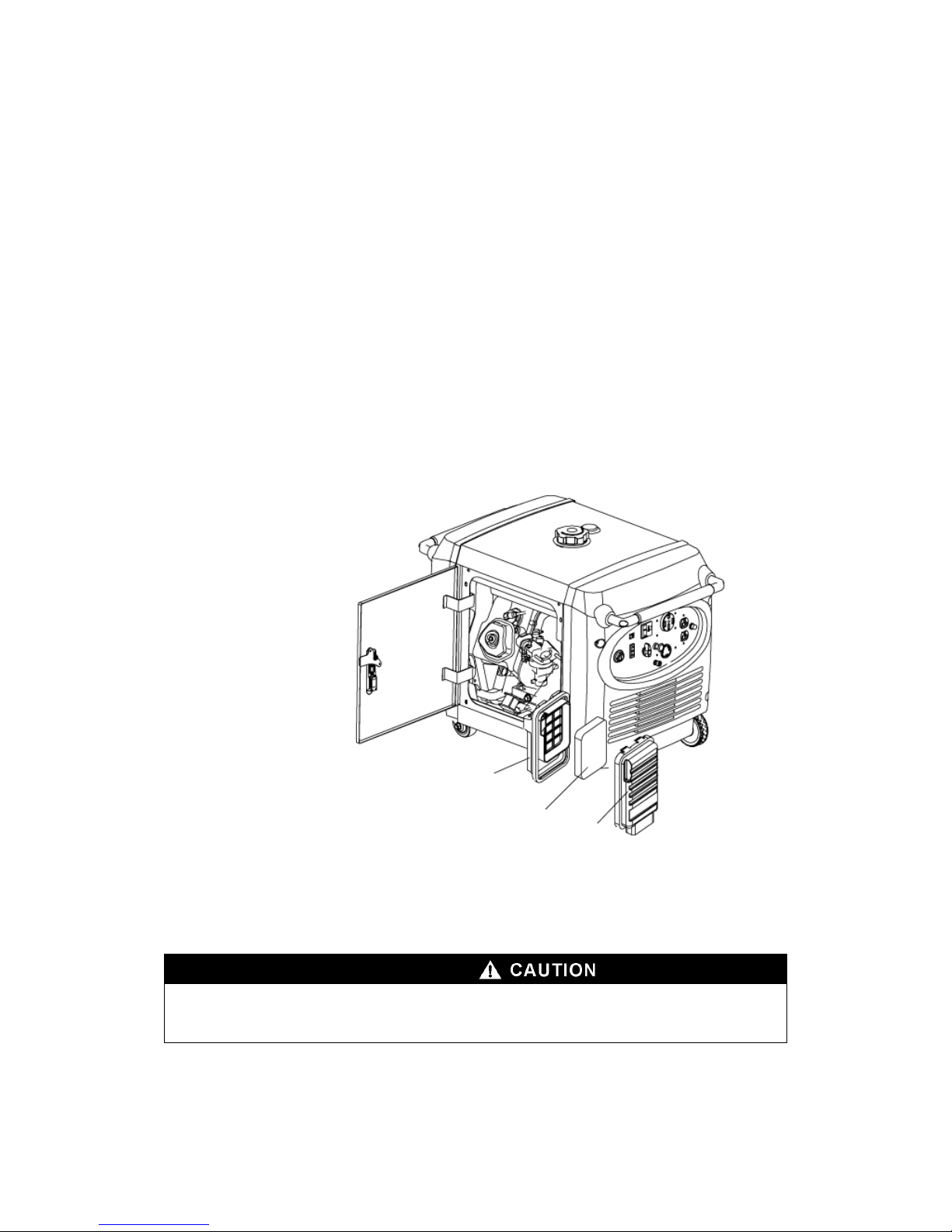
FUELS
be sure its octane rating is
.3 Check the air cleaner
heck the air cleaner elements to be sure they are clean and in good
ervice cover. Remove the air cleaner cover and remove the paper
GASOLINES CONTAINING ALTERNATE
If you decide to use a gasoline containing ethanol
no lower than the specification. Do not use a blend that contains more than
10% ethanol. Do not use gasoline containing methanol.
3
C
condition.
Open the s
air cleaner element. Replace the element if dirty or damaged.
Air Cleaner Assembly
lement
Air cleaner base
Air cleaner e
Air cleaner cover
■Never run the engine without the Rapid engine wear will result from air cleaner.
contaminants such as dust and dirt, being drawn through the carburetor, into the engine.
- 15 -
Page 17
- 16 -
4. STARTING THE GENERATOR
CAUTION
■ When starting the generator after adding fuel for the first time, after
long-term storage, or after running out of fuel, turn the fuel valve lever to the
"ON" position then wait 10 to 20 seconds before starting the engine.
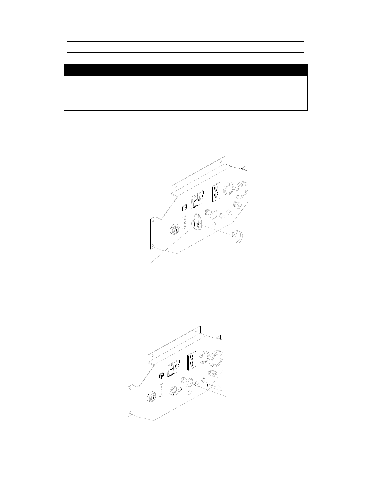
a. Turn the fuel valve lever to the ON position.
Fig. 7
b. Pull the choke knob out to the CLOSED position
Do not use the choke when the engine is warm or the air temperature is high,
燃油开关
Fuel Switch
阻风门开关
Choke Knob
- 16 -
Page 18
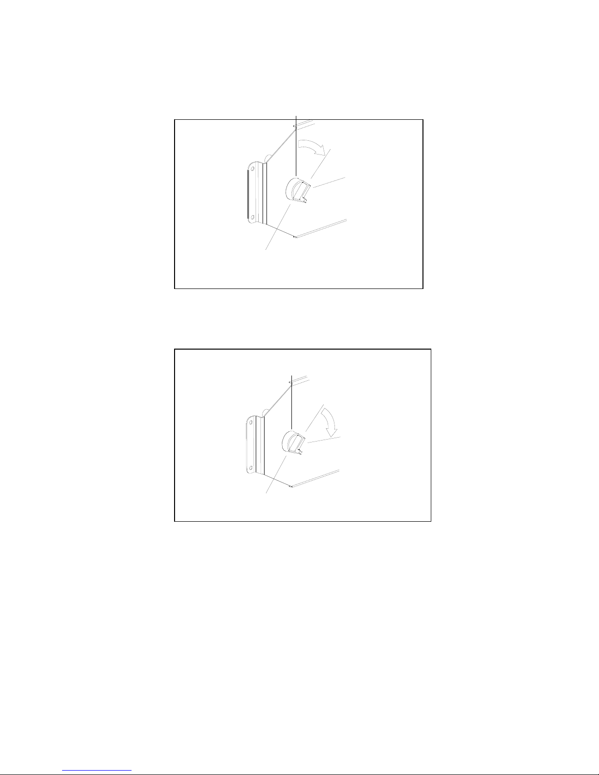
c. Insert the engine key and turn the ignition switch to ON position.
d. Turn the ignition switch to the START until the engine starts.
图 9 起动旋钮工作位置图
关
开
开始
发动机开关
OFF
ON
START
Ignition switch
发动机开关
关
开
开始
OFF
ON
START
Engine switch
- 17 -
Page 19
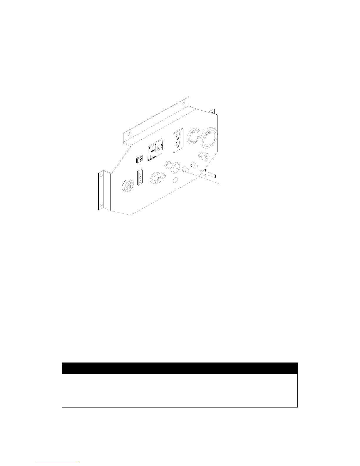
4.5 Push the choke knob to the OPEN position as the engine warms up
igh altitude operation
t high altitude, the standard carburetor air-fuel mixture will be excessively rich
erformance will decrease, and fuel consumption will increase.
igh altitude performance can be improved by installing a smaller diameter
ain fuel jet in the carburetor.. If you operate the generator at altitudes higher
an 5,000 feet (1,500m) above sea level, have your authorized dealer perform
e jet replacement..
ven with suitable carburetor jetting, engine horsepower will decrease
pproximately 3.5% for each 1000 feet (350m) increase in altitude. The effect
uretor
odification is made.
阻风门开关
Choke Knob
H
A
P
H
m
th
th
E
a
of altitude on the horsepower will be greater than this if no carb
m
CAUTION
■Operation of the generator at an altitude lower than the carburetor is jetted
for may result in reduced performance, overheating, and serious engine
damage caused by an excessively lean air/fuel mixture.
- 18 -
Page 20
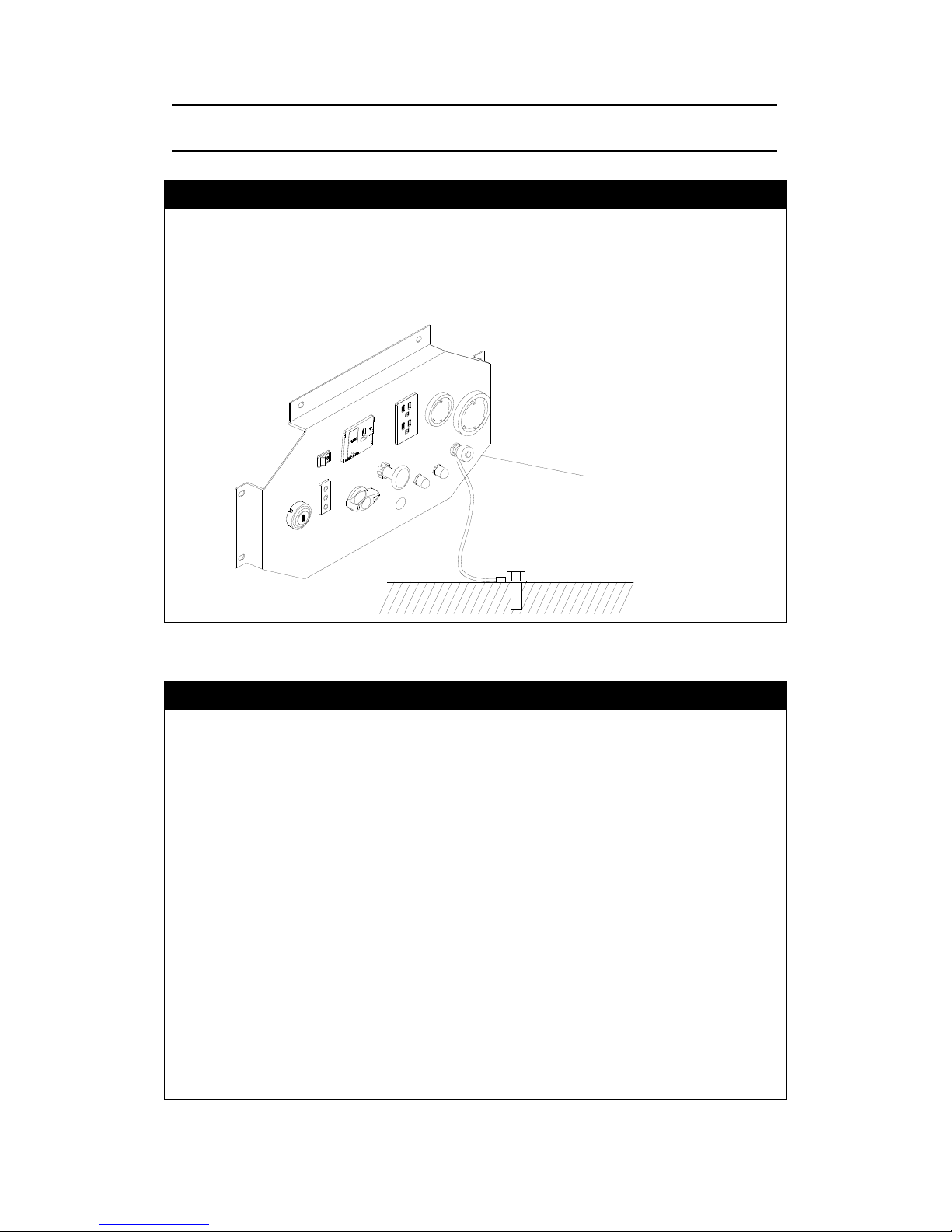
5. GENERATOR USE
WARNING
■To prevent electrical shock from faulty appliances, the generator should be
grounded. Connect a length of heavy wire between the generator's ground
terminal and an external ground source.
CAUTION
■ Limit operation requiring maximum power to 30 minutes. For continuous
operation do not exceed the rated power. In either case, the total wattage of all
or or to electrical appliances in the house.
■ Do not modify or use the ge other purposes than which it is
When an extension cable is required, be sure to use tough rubber sheathed
from other electric cables or wires such as
ommercial power supply lines.
appliances connected must be considered.
■ Do not exceed the current limit specified for any one receptacle.
■ Do not connect the generator to a household circuit. This could cause the
damage to the generat
nerator for
intended. Also observe the following when using the generator:
·Do not connect generators in parallel.
·Do not connect an extension to the exhaust pipe.
■
flexible cable.
■ Keep the generator away
c
接地端
Ground Terminal
- 19 -
Page 21
NOTE
■You may use DC receptacle when using AC supply.
■If you want to use AC and DC receptacle simultaneously, the total output
should not be over the sum output of AC and DC.
■Electrical equipment containing the wiring and plug should not have defect.
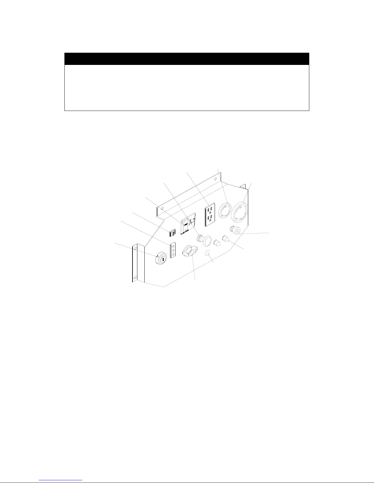
Control panel
直流插座
发动机开关
指示灯
智能节气门
阻风门手柄
接地端
燃油开关
电压选择开关
过载保护器
交流插座
交流插座
交流插座
GFCI Receptacle 120V 30A Receptacle
Ground Terminal
Overload Reset Switch
Voltage Selection Switch
Fuel Switch
Engine Switch
Indicator
Choke Handle 120/240V 30A Receptacle
DC Receptacle
Smart Throttle
- 20 -
Page 22
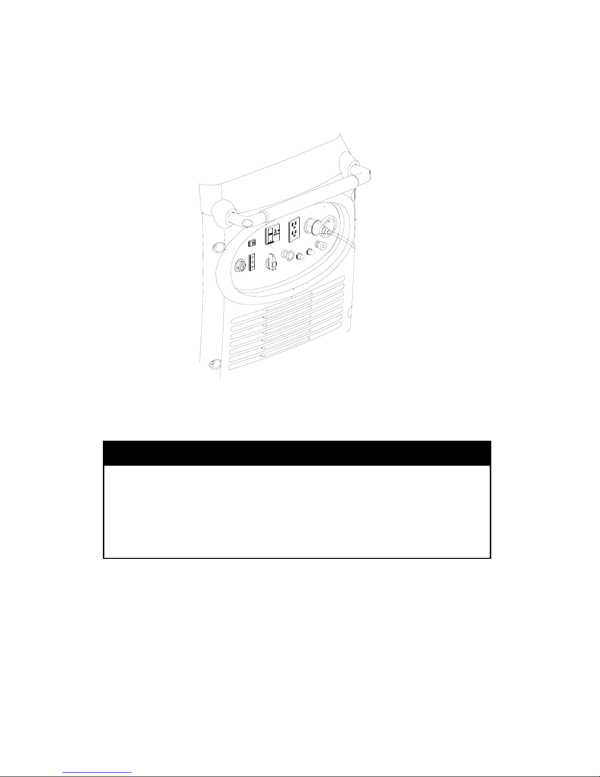
5.1 AC Application
icator light comes on.
witched off and plug in the
appliance.
1. Start the engine and make sure the green output ind
2. Confirm that the appliance to be used is s
CAUTION
■ Be sure that all appliances are in good working order before connecting
them to the generator. If an appliance begins to operate abnormally,
becomes sluggish, or stops suddenly, turn off the generator engine switch
immediately. Disconnect the appliance and examine it for signs of
malfunction.
- 21 -
Page 23
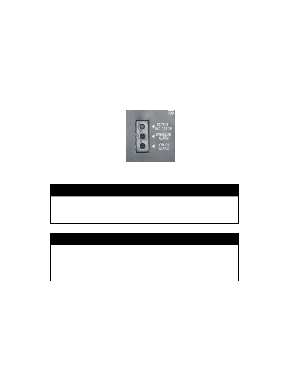
5.2 Output and Overload Indicators
he green output indicator light will remain ON during normal operating
d
rrent to the connected appliance will be shut off. Correct the
verload condition and press the overload reset switch on the panel to restore
AC power.
Check the engine oil level if the red low oil indicator comes ON.
T
conditions. If the generator is overloaded or if there is a short in the connecte
appliance the output indicator will go OFF and the overload indicator will go
ON and cu
o
NOTICE
■Before connecting an appliance to the generator, check that it is in good
order and that its electrical rating does not exceed that of the generator.
Then connect the power cord of the applianc art the engine. e and st
NOTICE
■When an electric motor is started, both the overload indicator light and the
output indicator light may go on simultaneously. This is normal if the overload
indicator light goes off after about four seconds. If the overload indicator light
tays on, consult your dealer. s
- 22 -
Page 24
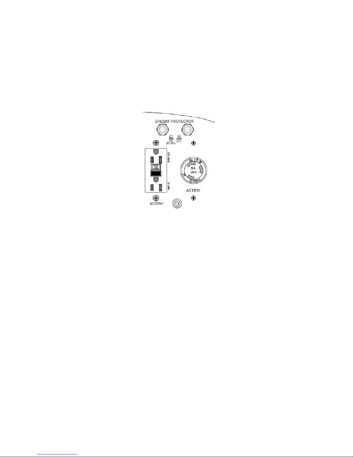
.
The two 120V receptacles are rated at 20 and 30 amps respectively.Should
.3 Voltage Selection Switch
generator
. If you operate the generator with the
switch in this position, the electric current is limited to 15 amps to the 120V
receptacles although it can prov ps at 240V from the 120/240V
. Total current is limited to 45.8 amps at rated
ad.
this current be exceeded, the circuit protection device willactivate and cut
allcurrent to the receptacle. This will be indicated by the push button popping
out. Reduce the load to the receptacle and reset the circuit protector by
pushing in the button.
5
The voltage selection switch has two positions: AC120V and AC120/240V.
1. When the voltage selection switch is in the 120/240V position, the
supplies both 120V and 240V AC power
ide 15 am
receptacle.
2. When the voltage selection switch in the 120V position, the generator
supplies 120V AC only. It can supply a full 30 amps to the 30 Amp receptacle
or 20A to the GFCI receptacle
lo
- 23 -
Page 25

- 24 -
.4 Smart Throttle
ttle is placed in the on position, engine speed is kept at
le automatically when the electrical load is disconnected and returns to the
roper speed required by the electrical load when the load is reconnected. The
ngine speed varies according to the amount of load applied to the generator.
lacing the smart throttle in the on position is recommended to minimize fuel
onsumption and engine noise while in operation.
■When high electrical load appliances are
connected simultaneously, turn the SMART
throttle switch to the OFF position to reduce
voltage fluctuation.
■The SMART throttle system does not operate
ciently if the electrical appliance will be used in
a rapid on-off or low to high rpm mode.
hen the smart throttle is in the off position, the engine runs at rated load
ults, the SMART throttle switch should be in the off position. Bring
ally hot weather conditions. Additionally, all other loads should be turned
ff until the air conditioner has started and is performing normally. It is also
portant to follow the air conditioner manufacturer's instructions for starting
nd restarting for proper operation. Some air conditioner manufacturers offer
5
When the SMART thro
id
p
e
P
c
effi
W
RPM.
5.5 Air Conditioning Operation
For best res
the generator to a normal operating temperature before applying the air
conditioning load. Always allow a 2 minute wait period when manually cycling
an air conditioner off and on. A longer wait period may be required under
unusu
o
im
a
Page 26

a start capacitor as an extra cost option. The lack of a start capacitor can
oner to draw too high a starting current and overload the
enerator. Contact your air conditioner dealer if you consistently have
roblems starting your air conditioner with the generator.
.6 DC Power Application
C motors. Output voltage is 15-3
prevent the possibility of creating sparks near the
ect the charging cable first to the generator
disconnect the vehicle's battery
sparks if
accidental contact is made between a battery terminal
■Do not attempt to start an automobile engine with the
generator still connected to battery. The generator may
maged.
■Connect the positive battery terminal to the positive
cause the air conditi
g
p
5
The DC receptacle may be used for charging 12 volt automotive-type batteries
only. It is not designed to operate D 0V. DC
output will vary according to the position of the Smart throttle switch.
a. Connect the charging cable to the DC receptacle of the generator and then
to the battery terminals.
■To
battery, conn
■B
then to the battery. Disconnect the cable first at the
battery.
efore connecting the charging cable to a battery that is
installed in a vehicle,
ground cable. Reconnect the vehicle's ground cable after
the charging cables are removed. This procedure will
prevent the possibility of a short circuit and
and the vehicle's frame or body.
be da
charging cord. Do not reverse the charging cables or
serious damage to the generator and/or battery may
occur.
- 25 -
Page 27
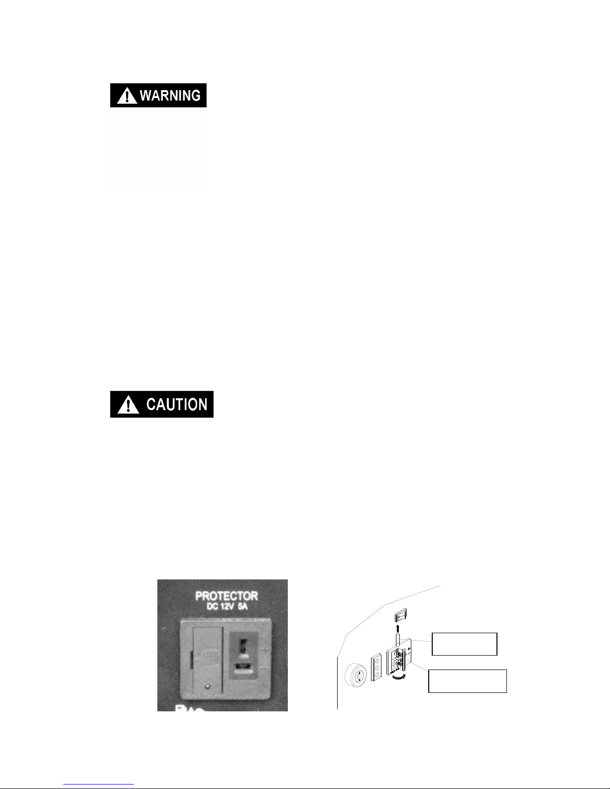
■The battery gives off explosive gases: keep sparks,
flames and cigarettes away. Provide adequate ventilation
when charging.
■The battery contains sulfuric acid (electrolyte). Contact
with skin or eyes may cause severe burns. Wear
protective clothing and a face shie
- 26 -
ld.
A. If electrolyte gets on your skin, flush with water.
B. If electrolytes gets in your eyes, flush with water for
at least 15 minutes and call a physician.
■ Electrolyte is poisonous.
c
l
a
If swallowed, drink large quantities of water or milk and
follow with milk of magnesia or vegetable oil and call a
physician.
■ Keep out of reach of children.
The DC output is to be used to charge batteries only.
Serious damage to the stator windings can occur if
connected to a DC motor or transformer.
b. St
■
■ The D
is overload
ease. T
eft of th
cause damage to the gener
art the generator.
The DC receptacle may b
C receptacle is prote
ed, the 5 amp fuse will blow
he red light on the D
e receptacle and is a
Replace the fuse with one of
e used while the AC power is in use.
cted from an overload with a fuse. If the DC circuit
and power to the DC receptacle will
C panel will illuminate. The fuse is located to the
ccessed by snapping open the access door.
the same capacity. Using a higher rated fuse may
tor alternator.
直流插座
保险丝
打开
Access door
5 amp fuse
Page 28

- 27 -
6. STOPPING THE GENERATOR
To stop the engine in an emergency, turn the engine switch OFF.
In normal use:
1. Switch off the connected equipment and pull the plug from the receptacle.
2. Turn off the ignition swit
3. Turn the fuel valve lever to
ch.
the OFF position.
Page 29

7. MAINTENANCE
The purpose of the maintenance and adjustment schedule is to keep the
■Shut off the engine before performing any
maintenance. If the engine must be run, make
t
ntains poisonous carbon monoxide gas.
or the equivalent.
The use of replacement parts which are not of
equivalent quality may damage the generator.
stem
mission source
xhaust gas contains carbon monoxide, nitrous oxide (NOx), and
ydrocarbons. It is very important to control the emissions of NOX and
ydrocarbons as they are a major contributor to air pollution. Carbon monoxide
vapors is a source of pollution as well.
a precise air-fuel ratio and emission control
ystem to reduce the emissions of carbon monoxide, NOX, hydrocarbons, and
vaporative fuel emissions.
egulation
our engine has been designed to meet current Environmental Protection
A) and the California Air Resources Board (CARB) clean air
tandards. The regulations dictate that the manufacturer provide operation and
aintenance standards regarding the emission control system. Tune up
pecifications are provided in the Specifications section and a description of
e emission control system may be found in the appendix to this manual,
dherence to the following instructions will ensure your engine meets the
mission control standards.
generator in the best operating condition.
sure the area is well ventilated. The exhaus
co
■Use genuine Voltmaster parts
7.1 Emission Control Sy
E
E
h
h
is a poisonous gas. The emission of fuel
The generator engine employs
s
e
R
Y
Agency (EP
s
m
s
th
A
e
- 28 -
Page 30

Modification
odification of the emission control system may lead to increased emissions.
z Disassembling or modifying the function or parts of the intake, fuel
or exhaust system.
r destroying the speed governing function of the
. Consult with your
authorized Voltmaster service
z Hard starting or s
z Unstable idle spe
z Shut down or ba
z Backfire or afte
z Black smoke and/or excessive fuel consumption
Replacement parts and acc
rol system applied to the engine have
certified by the regulatory agencies. You can
replacement parts have been manufactured to the
ing to the maintenance schedule in this section.
s more frequently when used in dusty areas, or under conditions
M
Modification is defined as the following:
z Modifying o
generator.
Engine faults that may affect emission
Any of the following faults must be repaired immediately
center for diagnosis and repair:
hut down after starting
ed
ckfire after applying an electrical load
rfire.
essories
The parts making up the emission cont
been specifically approved and
trust that Voltmaster
same production standard as the original parts. The use of replacement parts
or accessories which are not supplied by Voltmaster may affect the engine
emission performance. The manufacturers of replacement parts and
accessories have the responsibility to guarantee that their replacement
products will not adversely affect emission performance.
Maintenance
Maintain the generator accord
Service item
of high load, temperature, and humidity.
- 29 -
Page 31
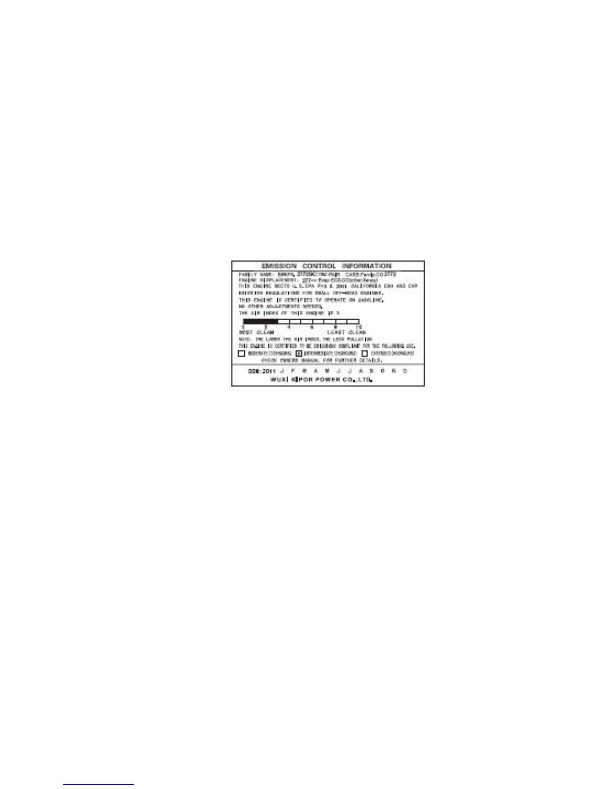
Air Quality Index (only for California certified models)
ARB requires that an air quality index label be attached to every certified
ngine showing the engine emission information for the emission duration
label is provided for the user to compare the emission
erformance of different engines. The lower the air index, the better the engine
iod and the service life of emission
infor
C
e
period. The
p
emission performance. The description of durability is helpful for the user to
learn the engine emission duration per
control system. Refer to the warranty section of this owner’s manual for more
mation.
.
- 30 -
Page 32
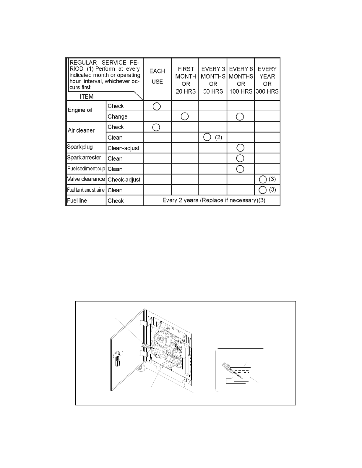
7.2 Maintenance Schedule
.
r
OTE: (1) Log hours of operation to determine proper maintenance.
(2) Service more frequently when used in dusty areas.
(3) These items should be serviced by an authorized dealer unless
the owner has the proper tools and is mechanically proficient. See the
service manual.
3 Changing Oil
ain the oil while the engine is still warm.
N
7
D
Dipstick
上限位
下限位
Upper limit
Lower limit
Oil drain bolt
- 31 -
Page 33

1. Open the left side maintenance cover.
. Take out the oil outlet plug.
. Remove the drain bolt, and drain the oil. Retighten the bolt securely.
. Refill with the recommended oil and check the level.
nce cover.
ngine oil capacity: 1.1L
2
3
4
5. Close the left side maintena
E
NOTE
■ Please dispose of used motor oil in a manner that is compatible with the
environment. We suggest you take it in a sealed container to your local service
station for reclamation. Do not throw it in the trash or pour it on the ground.
7.4 Air Cleaner Service
A dirty air cleaner will restrict air flow to the carburetor to prevent carburetor
malfunction, service the air cleaner regularly. Service more frequently when
operating the generator in extremely dusty areas.
WARNING
■ Do not use gasoline or low flash point solvents for cleaning. They are
flammable and explosive under certain conditions.
CAUTION
■Never run the generator without the air cleaner. Rapid engine wear may
result
1. Open
2. Unsna e the air cleaner cover.
. Inspect the air cleaner. Replace if dirty or the replacement is called for
peration.
. Close and latch the left side maintenance cover.
the left side maintenance cover.
p the clips, remov
3
based on hours of o
4. Reinstall the air cleaner cover.
5
- 32 -
Page 34

.
operation, the spark plug must be properly gapped
nd free of deposits.
1. Open the left side maintenance c
. Visually inspect the spark plug. Discard it if the insulator is cracked or
chipped
sure the plug gap with a feeler gauge.
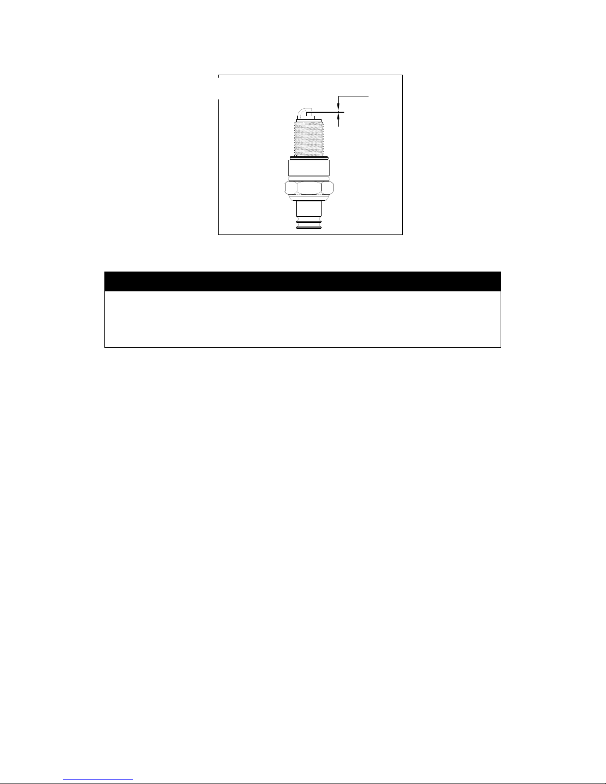
he gap should be 0.7-0.8mm (0.028-0.031in). Correct as necessary by
7.5 Spark Plug Service
Recommended spark plug: WR7DC
To ensure proper engine
a
over.
2. Remove the spark plug cap.
Fig, 15
Spark plug wrench
Spark plug
3. Clean dirt from around the spark plug base.
4. Use the wrench to remove the spark plug.
5
Clean the spark plug with a wire brush if it is to be reused.
6. Mea
T
carefully bending the side electrode.
- 33 -
Page 35
- 34 -
0.7-0.8
火花塞间隙
Spark plug clearance
CAUTION
■ The spark plug must be securely tightened. An improperly tightened plug
an become very hot and possibly damage the generator.
Never use a spark plug with an improper heat range.
c
■
7. Install the spark plug carefully, by hand, to avoid cross-threading.
. After a new spark plug has been seated by hand, it should be tightened 1/2
rn with a wrench to compress its washer.
installed, it should only require 1/8 to 1/4 turn after
e left side maintenance cover.
8
tu
If a used plug is being re
being seated.
9. Reinstall the spark plug inspection cover and tighten the cover screw.
10. Close and latch th
Page 36
7.6 Spark Arrestor Maintenance
Fig, 17
火星捕捉器
WARNING
■ If the generator has been running, the muffler will be very hot. Allow it to
cool before proceeding.
CAUTION
■ The spark arrester must be serviced every 100 hours to maintain its
efficiency.
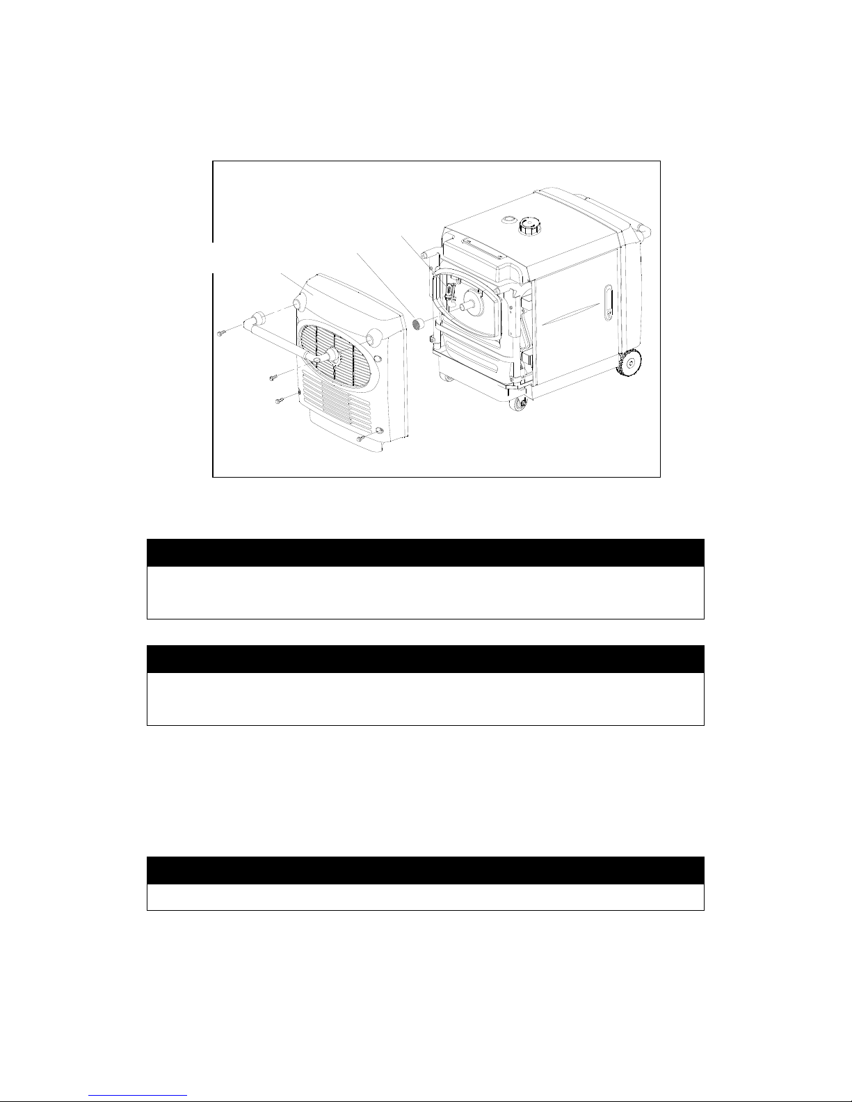
1. Remove the back cover.
2. Remove the exhaust tail pipe and spark arrester.
3. Use a brush to remove carbon deposits from the spark arrester screen.
NOTE
■ Inspect the spark arrester screen for holes or tears. Replace if necessary.
4. Reinstall the spark arrester.
. Reinstall the upper muffler protector. 5
后面罩
二次补气阀
Secondary gulp valve
Spark arrester
Rear cover
- 35 -
Page 37
8. TRANSPORTING/STORAGE
. When transporting the generator, turn the fuel valve lever OFF and keep the
enerator level to prevent fuel spillage. Fuel vapor or spilled fuel may ignite.
o not transport the generator in a vehicle with fuel in the tank.
is essential that the generator be exercised on a regular basis. This will
h or sludge in the fuel system and also
move moisture from the generator windings. Additionally, seals and other
oving engine parts are kept lubricated and the battery is recharged.
xercise the generator by running it with at least a 1/2 load (1500W) for 60
inutes per month. G nts to prevent contamination of your
el supply are available from your dealer. Fuel varnishing necessitating
is not a warrantable failure.
. Before storing the unit for an extended period:
. Ensure the storage area is free of excessive humidity and dust.
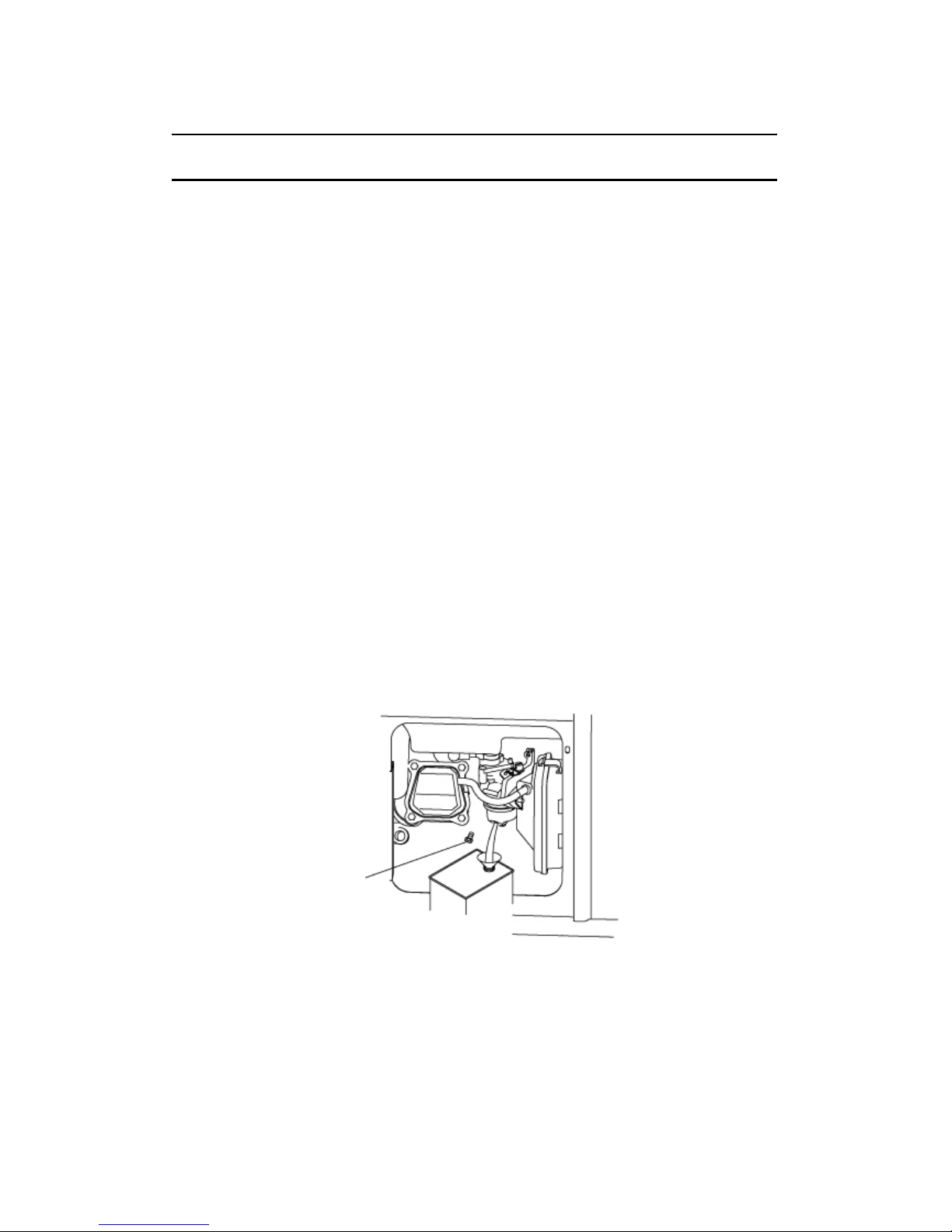
. Drain the fuel
. Open the left side maintenance cover.
. Turn fuel valve lever to ON and then loosen the carburetor drain screw.
rain the gasoline from the carburetor and fuel tank into a suitable container.
a
g
D
b. Exercising the generator
It
prevent the accumulation of varnis
re
m
E
m asoline fuel treatme
fu
replacement of the carburetor
c
1
2
A
B
D
Drain plug
Fig.19 Drain the fuel
.
the engine oil.
. Remove the spark plug and pour one tablespoon of clean engine oil into the
several revolutions to distribute the oil and then
reinstall the spark plug.
3. Once a month, recharge the battery
4. Change
5
cylinder. Crank the engine
- 36 -
Page 38
9. TROUBLESHOOTING
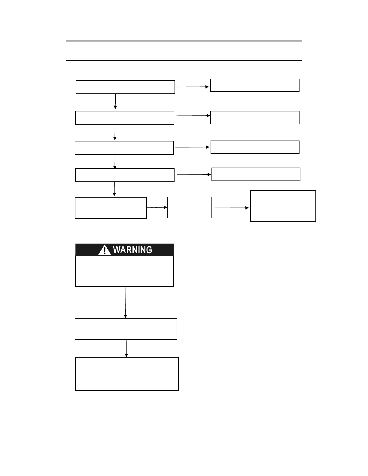
When the engine will not start:
NO
.
If the engine still does not start, take
the generator to an authorized
service center.
Refill the fuel tank.
Is there fuel in the tank?
YES
Is the fuel reaching the carburetor?
■ Be sure there is no spilled
fuel around the spark plug. Spilled
fuel may ignite.
Is there a spark from
the spark plug?
Replace the
spark plug
Take the generator to
an authorized service
center.
Add the recommended oil.
Is there enough oil in the engine?
Is the fuel valve on?
Is the engine switch on?
Turn the fuel valve on.
Turn the engine switch on.
YES
YES
YES
NO
NO
NO
NO
Still no spark
To check:
1) Remove the spark plug cap and clean any
park
e electrode on the cylinder
head to ground.
the engine; sparks should jump across
To check:
rain
2) Fuel should flow from the drain when the fuel
valve is turned on.
dirt from around the spark plug.
2) Remove the spark plug and install the s
plug in the plug cap.
3) Set the plug sid
4) Crank
the gap.
1) Turn off the fuel valve and loosen the d
screw.
- 37 -
Page 39
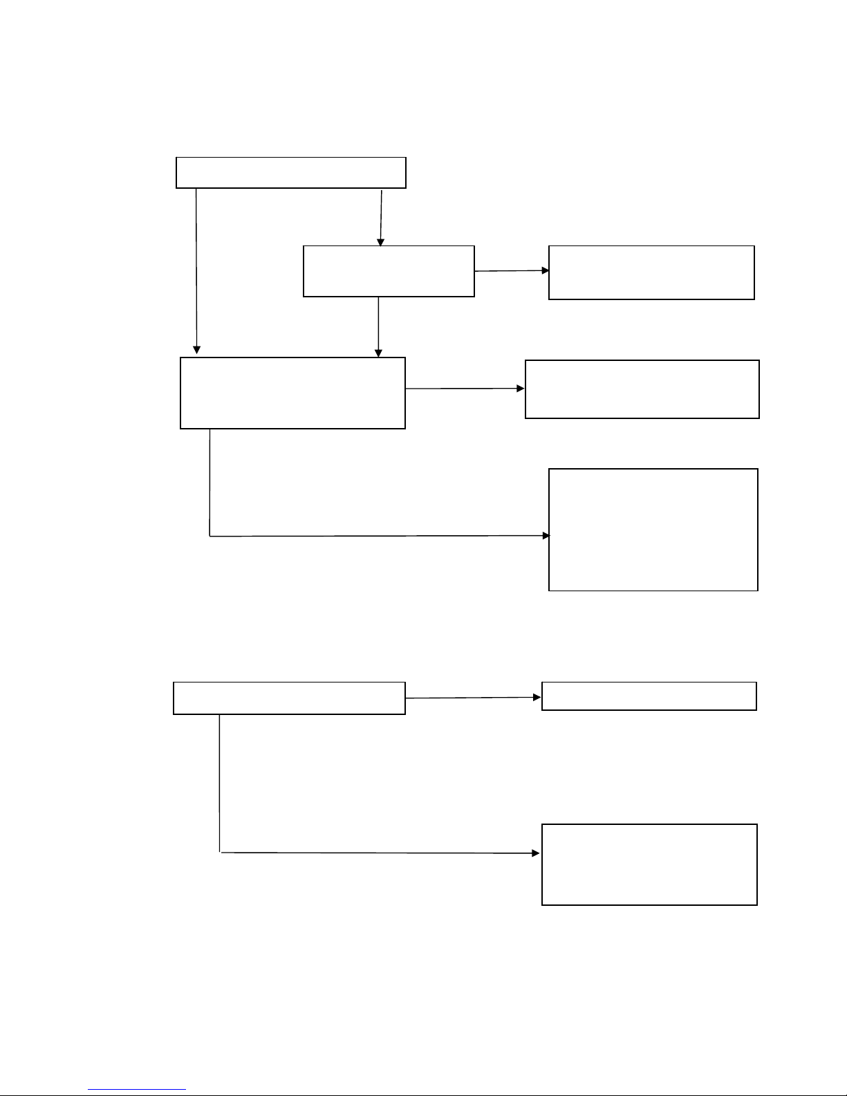
AC appliance does not operate:
No output at the DC receptacle:
Is the output indicator light ON?
NO
NO
YES
NO
Is the overlo
light ON?
Take the generator to an
authorized service center.
ad indicator
YES
NO
Check the electrical appliance or
Take the generator to an
equipment for any defects.
authorized service center.
■ Replace the electrical
appliance or equipment.
■Take the electrical appliance
or equipment to an electrical
shop for repair.
Is the fuse blown?
Replace the fuse.
Take the generator to an
authorized service center.
YES
YES
- 38 -
Page 40

- 39 -
10. SPECIFICATIONS
ENERATOR G
Model VI6000
Rated 60 frequency (Hz)
Rated voltage (V) 120/240
Rated current (A) 45.8/22.9
Rated output (Watts) 5500
Max output (Watts) 6000
DC voltage [email protected]
Phase Single
ENGINE
odel KG390GTi M
Type cylinder, 4 stro HV,
gasoline engine
Single ke, vertical, air-cooled, O
Displacement (Bore ke) × Stro
23.7 cu. In. (389 cc)
Com 8.5:1 pression ration
Rate (r/min))] 7.7/3600 d power [kW(hp)/
Rated rotation speed (rpm) 3600
Ignition system T. C. I
Spark plug WR7DC
Starting system Electric starter/manual recoil
Fuel ive unl Automot eaded gasoline, 87 octane
Lube W30 (a oil SAE 10 bove CC grade)
Lube 1.2 qt. (1.1L) oil capacity
GENERAL
Fuel tank capacity (L) 5.8gal.(22L)
Continuous running time at rated
output
7.5 Hours
Nois
(7M)
64-65 decibels e level(zero load~ full load) @ 23'
Overall dimension (L×W×H) in. (mm) 48.6×25.59×30.3 (1235×650×770)
Dry weight –lbs (kg) 263 (115)
Tun ations
Spark Plug Gap 0.024-0.028 in (0.6-0.7 mm)
e Up Specific
Valve Clearance- cold (Intake) 0.0039 ±.0008 in (0.10 ± 0.02 mm)
Valve Clearance- cold (Exhaust) 0.0059 ± .0008 in (0.10 ± 0.02 mm)
Page 41
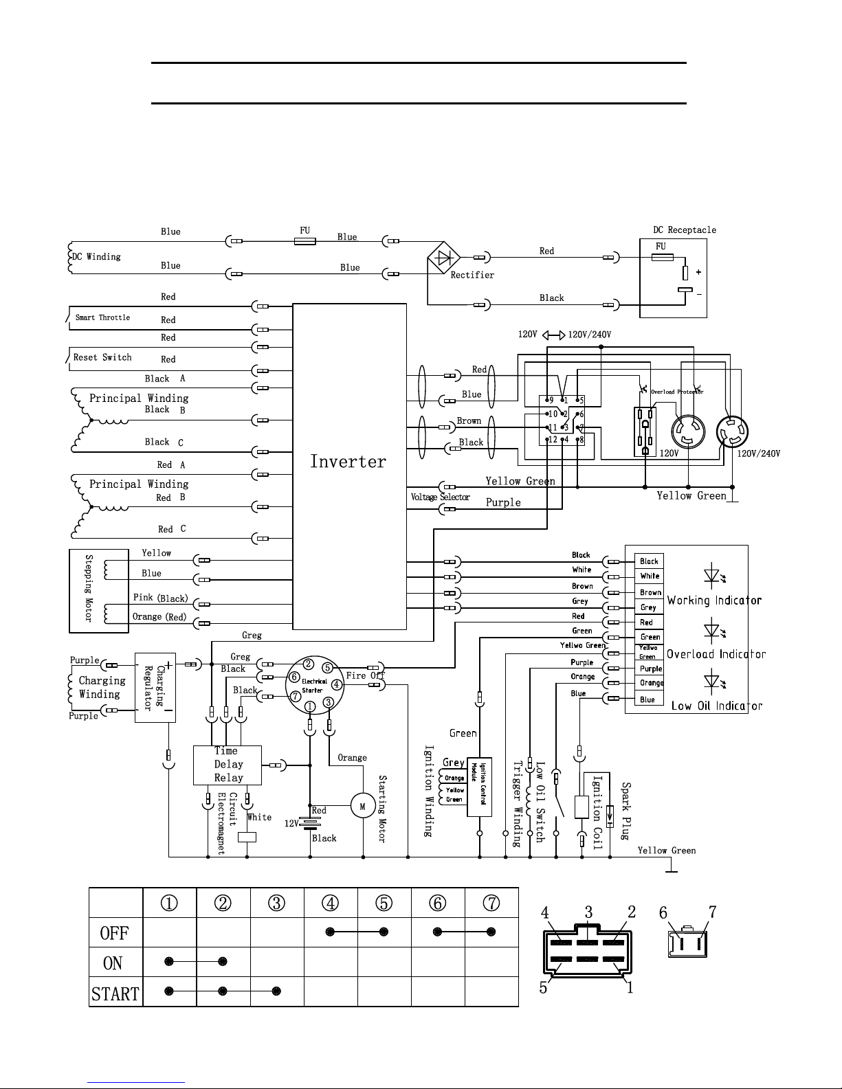
11. WIRING DIAGRAM
- 4 -
Page 42
- 41 -
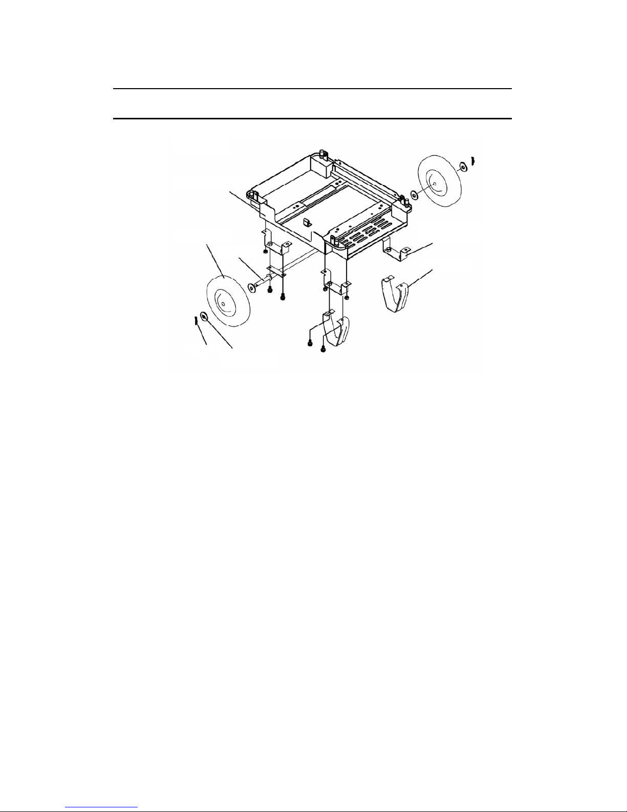
12. WHEEL KIT
1
5
2
4
3
7 6
1. Chassis- installed 5. 10” Wheel
2. Support Bracket- (4) 6. Wheel Washer (4)
3. Front Stabilizer (2) 7. Wheel Clip
4. Axle Assembly
ssembly:
1. Install the four support brackets and secure with bolts.
2. Attach the front stabilizers to the chassis (below the handles)
3. Attach the axle assembly.
4. Install one washer on the axle against each welded stop.
5. Install the two wheels.
6. Install the two remaining washers and secure with the wheel clips.
he handles are preassembled before packaging. To raise the handles, simply raise the
andle assembly to a horizontal position. To retract the handles, slide the chrome collars
ward you to clear the sleeve and lower them to the starting position.
A
T
h
to
Page 43

WANCO INC.
5870 Tennyson Street
Arvada, Colorado 80003
800-730-3927
303-427-5700
303-427-5725 fax
www.voltmaster.com
©2015 Wanco Inc. All rights reserved.
Voltmaster is a Wanco brand. Voltmaster, Wanco, and the Voltmaster and Wanco logos are registered
trademarks of Wanco Inc. All other trademarks are property of their respective owners.
 Loading...