

Page 1
Form 2593-PTO
REV. 7/06
MODEL: PTO 30/25
MODELS: PTO 40, 50, 55,
65, 70, 75, 90, 110 SERIES
MODEL: PTO 15/12
PTO SERIES OWNERS MANUAL
PTO 15/12, PTO 30/25
PTO 40-1, PTO 50-1, PTO 65-1, PTO 75-1
PTO 55-3, PTO 70-3, PTO 90-3, PTO 110-3
Page 2
2
Safety First
While safety is built into every
generator, imprudent operation,
negligent maintenance or carelessness
can contribute to present serious
hazards to life and injury.
Keep a fire extinguisher nearby. Know
its proper use. Consult your local fire
department for the correct
extinguisher type. Extinguishers rated
ABC by the NFPA are appropriate for
most applications. Annually service
the extinguishers and perform service
as required.
Be sure the generator is well
ventilated. Do not operate this
generator in an enclosed compartment.
All warranties are voided if operated in
an enclosed compartment.
Provide adequate ventilation for the
prime mover engine on the tractor.
The output power voltage present
in this equipment can cause a fatal
electric shock. This equipment
must only be operated by a responsible
adult.
Do not allow anyone to operate the
generator without proper instructions.
Guard against electric shock.
Avoid direct contact with live
terminals or receptacles.
Do not operate this unit in rain
or snow.
Use only 120 volt 3-wire grounded
plugs and 240 volt 4-wire grounded
plugs, connectors and extension cords.
This unit must be properly grounded
by the operator according to the
National Electric Code and the
Occupational Safety and Health
Administration (OSHA).
Safety Symbols
These symbols alert you to potential
personal injury situations. Follow the
Information to avoid possible injury
or death.
This symbol
indicates imminent
hazardous situations, which, if not
avoided, WILL result in death or serious
personal injury.
This symbol
indicates a
potentially hazardous situation,
which, if not avoided, COULD result
in death or serious personal injury.
This symbol
indicates a
potentially hazardous situation,
which, if not avoided, MAY result in
personal injury.
Visual Inspection
Visually inspect the unit before the
initial start. Check for loose or missing
parts and any damage that may have
occurred in shipment. You must
remove the generator from the
wooden mounting base.
Ground Mounting
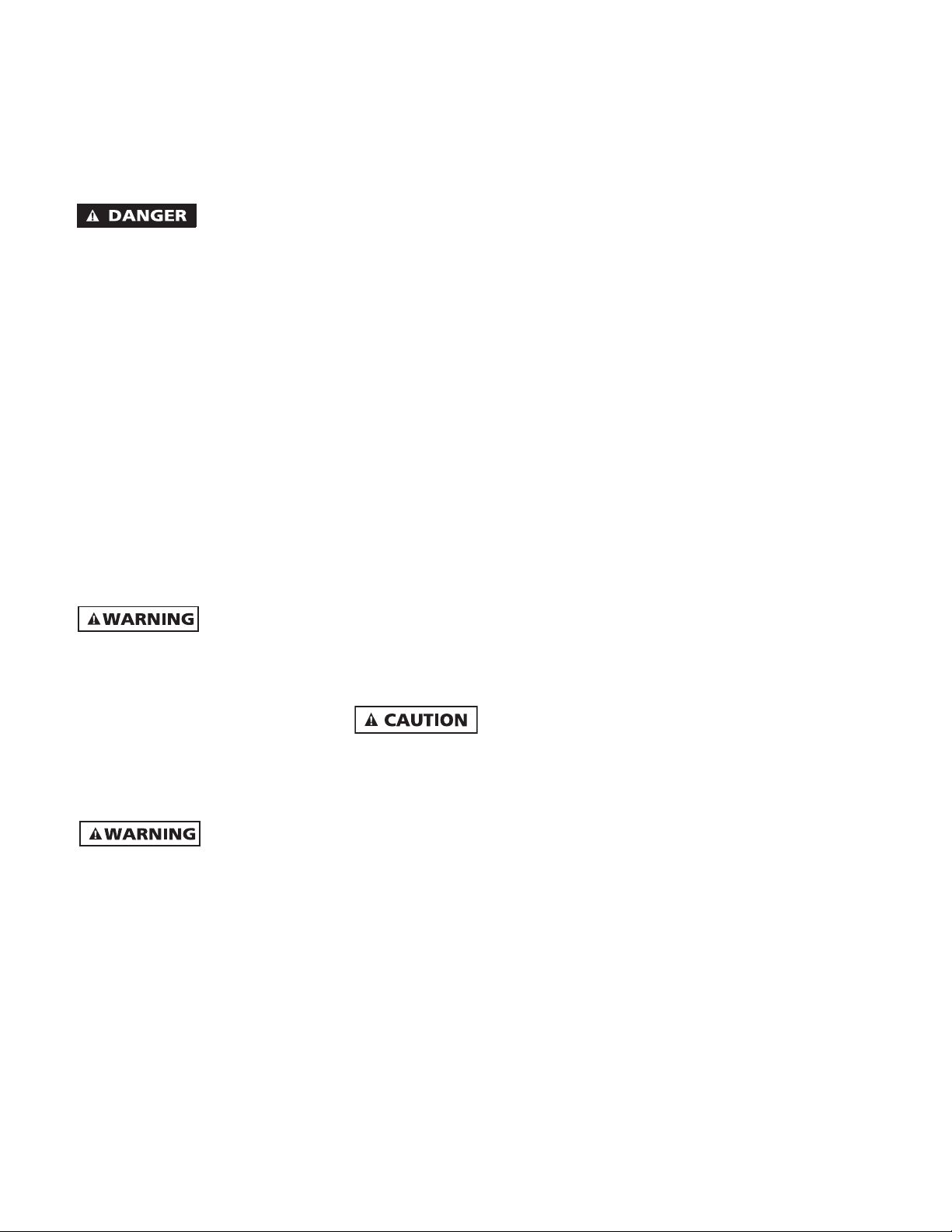
See figures 1 and
2 for installation
on a concrete slab with mounting
dimensions. Failure to mount securely
will result in damage to the generator
and possible personal injury or death.
Trailer Mounting
(Optional Accessory) 3403
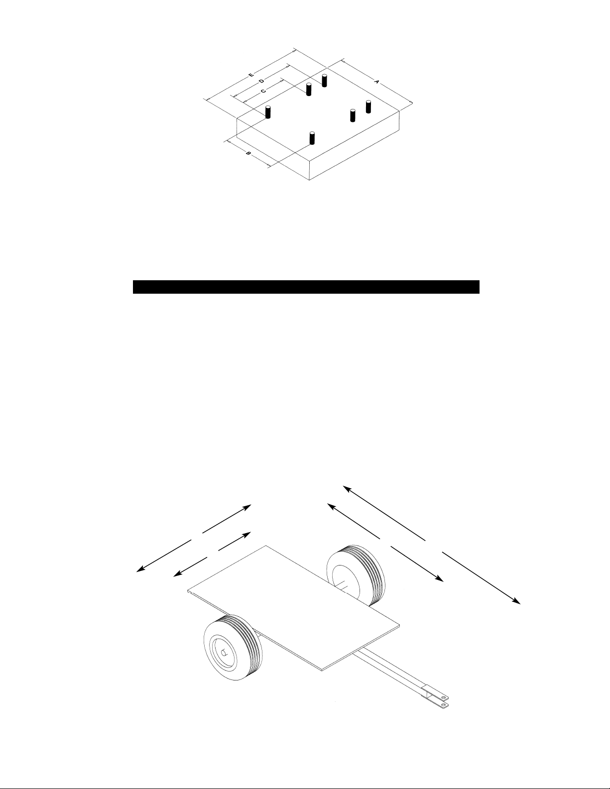
See figure 3 for a
typical example of
a trailer. Mount the generator on a
trailer if you plan to use the generator
as a portable source of power. The
trailer should first be connected to the
tractor. Next the generator should be
All pulleys, shafts, belts must be
protected with safety guards
properly installed before operating
the equipment.
When working on or around this
generator, do not wear neckties or
loose clothing, jackets or sleeves that
may become caught in moving parts.
Only a qualified technician should
perform repairs on this equipment.
Do not work on this equipment while
fatigued or under the influence of
alcohol or drugs. Use extreme caution
when working on electrical
components. High output voltages
from this equipment can cause injury
or death.
When working around engines use
noise suppression equipment and
wear protective devices as necessary.
Excessive noise is not only tiring, but
continual exposure can lead to loss
of hearing.
Installing and wiring a home or
building to a PTO generator is not a
do-it-yourself project. Consult a
qualified licensed electrician or
contractor. This installation must
comply with all national and local
electrical codes.
Do not connect this generator to a
home or building except through an
isolation transfer switch (double pole
double throw).
When wiring an electrically driven
pump, follow all electrical and safety
codes, as well as the most recent
United States National Electrical Code
(NEC) and the Occupational Safety and
Health Act (OSHA).
ISOLATION SWITCH 6&7
WIRING DIAGRAMS 8&9
PARTS EXPLOSIONS 10,11,12,13,14&15
ADJUSTING VOLTAGE 16
OPERATING SHAFT SPEED 16
GUARDS 169
CONNECTIONS 17
ORDERING PARTS 18
WARRANTY 18
SAFETY 2
TRAILER MOUNTING 2&3
THREE POINT HITCH 3
OPERATING 3
FULL POWER CONNECTOR 3&4
GROUNDING 4
SHAFT INSTALLATION 4&9
GEAR BOX 4
MAINTENANCE 4
MOUNTING 5&6
TABLE OF CONTENTS
Page 3

3
placed on the trailer and connected
with the shaft to the tractor and
generator. IMPORTANT The generator
MUST be mounted forward of the
trailer axle to prevent the trailer from
tipping backwards which can cause
personal injury or death. Once the
positioning of the generator, shaft and
relationship to the axles has been
determined, secure the generator using
4 hex bolts of at least 3/8 inch diameter
with washers and nuts. Drilling four
holes will be required. It is strongly
recommended that the axle length be
at least 41 inches before the wheel
hubs. This width is recommended to
prevent the torque required to turn the
generator from causing the generator
and trailer from tipping over. The
trailer height should enable aligning
the drive shaft in a straight or nearly
straight line between the tractor PTO
and the generator PTO. Misalignment
must be less than 10 degrees during
operation even though the mechanical
design of the shaft would allow greater
misalignment. This optional trailer can
be ordered from your local dealer.
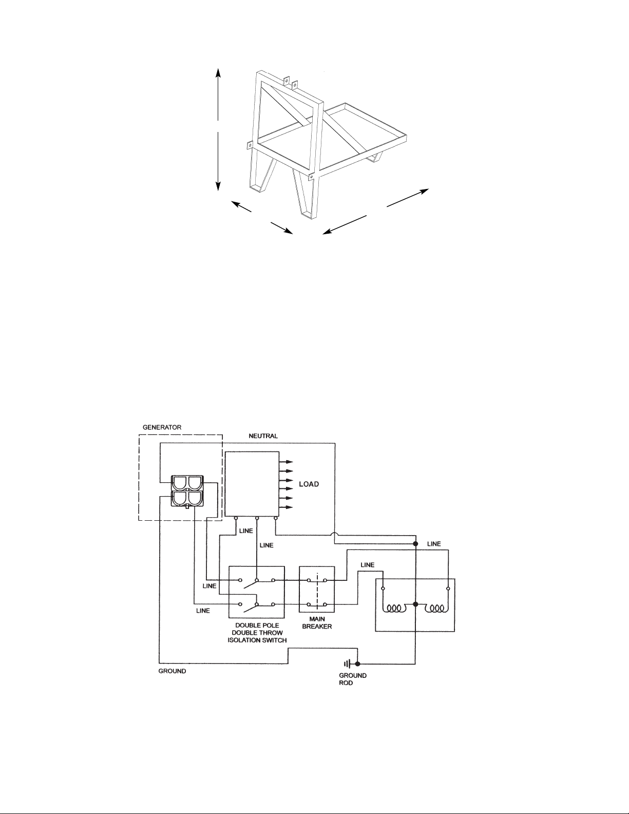
Three Point Hitch
(Optional Accessory)3418
See figure 4 for
a typical example
of a three point hitch. Mount the three
point hitch to the tractor. Place the
generator on the three point hitch.
Attach the shaft to the generator and
the tractor PTO’s. Once the positioning
of the generator, shaft and relationship
on the three point hitch has been
determined, secure the generator using
4 hex bolts of at least 3/8 inch diameter
with washers and nuts. The height of
the generator should enable aligning
the drive shaft in a straight or nearly
straight line between the tractor PTO
and the generator PTO. Misalignment
must be less than 10 degrees during
operation even though the mechanical
design of the shaft would allow greater
misalignment.This optional hitch can be
ordered from your local dealer. Drilling
four holes will be required.
Operating The Generator
Keep the area
around the
generator clear of all debris, rags etc.
Do not smoke around the generator or
tractor. Be certain the generator is
properly grounded. Turn the main 2
pole circuit breaker on the generator to
the off position. Be certain all of the
safety guards are in place. Check the
gear box inspection plate to verify that
gear oil is up to the level of the
inspection point. Do not overfill the oil
in the gear box. Remove any weather
protective covers that may have been
put over the generator before
operating the unit. Make certain that
the generator is properly mounted on a
secure location (concrete slab, trailer or
three point hitch), no people or
children are around the generator and
plug in the electrical load into the
receptacle or full power connector.
Make certain that the tractor wheels
are blocked to prevent the tractor from
moving and the parking brake is
applied. Start the tractor and at low
idling speed engage the PTO to the
generator. Slowly bring up the speed in
the generator until the volt meter
reads at least 240 volts on the PTO
15/12 and PTO 30/25 (which is 60 hertz)
or 60 hertz on the other PTOs (which is
240 volts) and lock the tractor speed.
Lower voltage, below 240 volts or
below 60 hertz is worse than slightly
higher voltage or slightly higher
frequency. When the tractor and
generator are operating properly, turn
the isolation switch from the utility
position to the off position and then to
the generator position. Next, switch
the main 2 pole circuit breaker on the
generator
to the on position and you are now
being powered by the PTO generator.
Do not open any protective covers,
control panels, etc. while the generator
is operating.
When it is time to stop operating the
generator, you must first remove either
the electrical load from the generator
circuit breaker to the off position.
Do not slow the generator speed down
with an electrical load on the generator
or damage to the generator and load
will occur. Bring the tractor PTO speed
down to idle and shut the tractor PTO
off. You would then switch the
isolation switch back to normal
utility power.
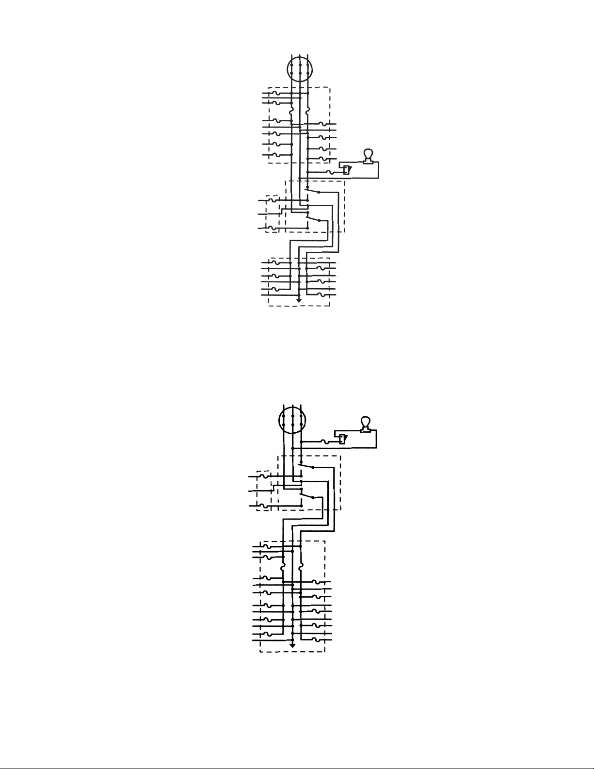
Isolation Switch and
Isolation Circuits
See figure 5 for the proper installation
of a customer supplied isolation switch.
Installation of an
isolation switch
must be done by a licensed electrician.
Back feeding of electrical power from a
generator without a proper isolation
switch installed can kill service
personnel working on power lines
and/or damage equipment when the
utility returns normal power. See figure
5 for a sample wiring of an isolation
switch. Do not operate this generator
in parallel with another generator. The
isolation switch has three positions,
utility position, off and generator
position. The National Electrical Code
and local codes require an isolation
switch be installed between a standby
generator (such as a PTO generator)
and the utility lines. See figures 6 and 7
for Isolation Circuits.
Full Power Connector
Installation
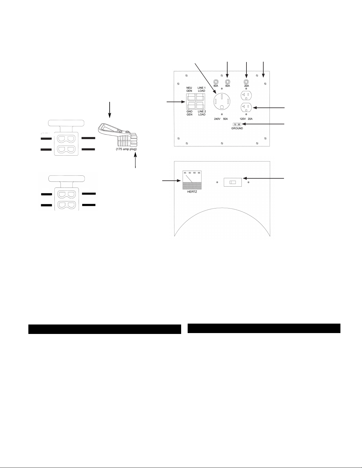
See figures 15 and
17 . The connector
has been assembled at the factory. Only
a licensed electrician should install the
wire cables to the connector. Failure to
properly connect the wires will result in
damage to the equipment and/or
personal injury. Consult a wire
ampacity chart for the proper wire
gauge size for a given generator. You
must use stranded copper welding
cable with a 600 volt rating and a
minimum of 3AWG hypalon insulation.
The wires must be stripped about 0.75
inch from the end of the cable. Insert
the end of the wire into the open
Page 4
or turn the generator main 2 pole
contact. Use a heavy crimping tool to
secure the wire into the contact. Insert
the four contacts into the full power
connector making certain that they are
securely in place.
Grounding
Proper grounding
will prevent an
electric shock in the event loss of
internal ground or loss of a ground in
the load. The National Electric Code
requires at least a number 12AWG
stranded copper wire to the grounding
lug on the generator. Connect the lug
to a copper or brass grounding rod
driven into the earth. DO NOT attach
ground connections to gas or water
pipes.
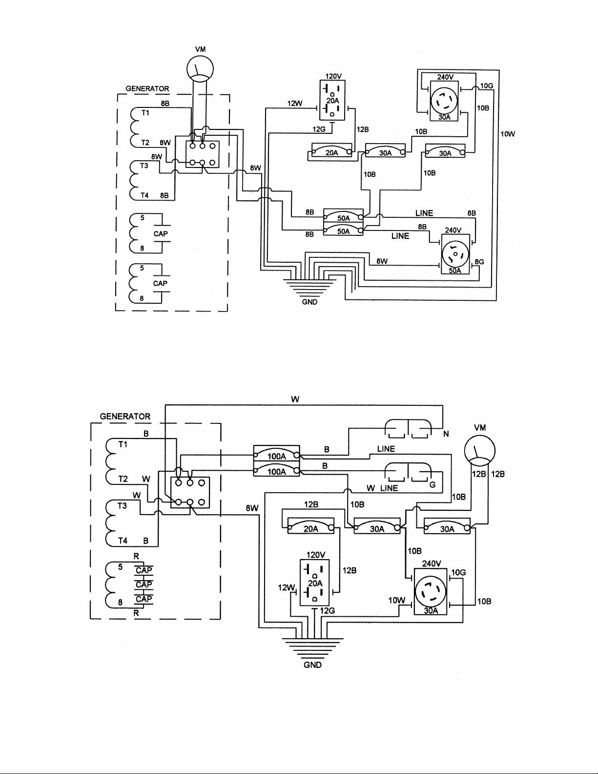
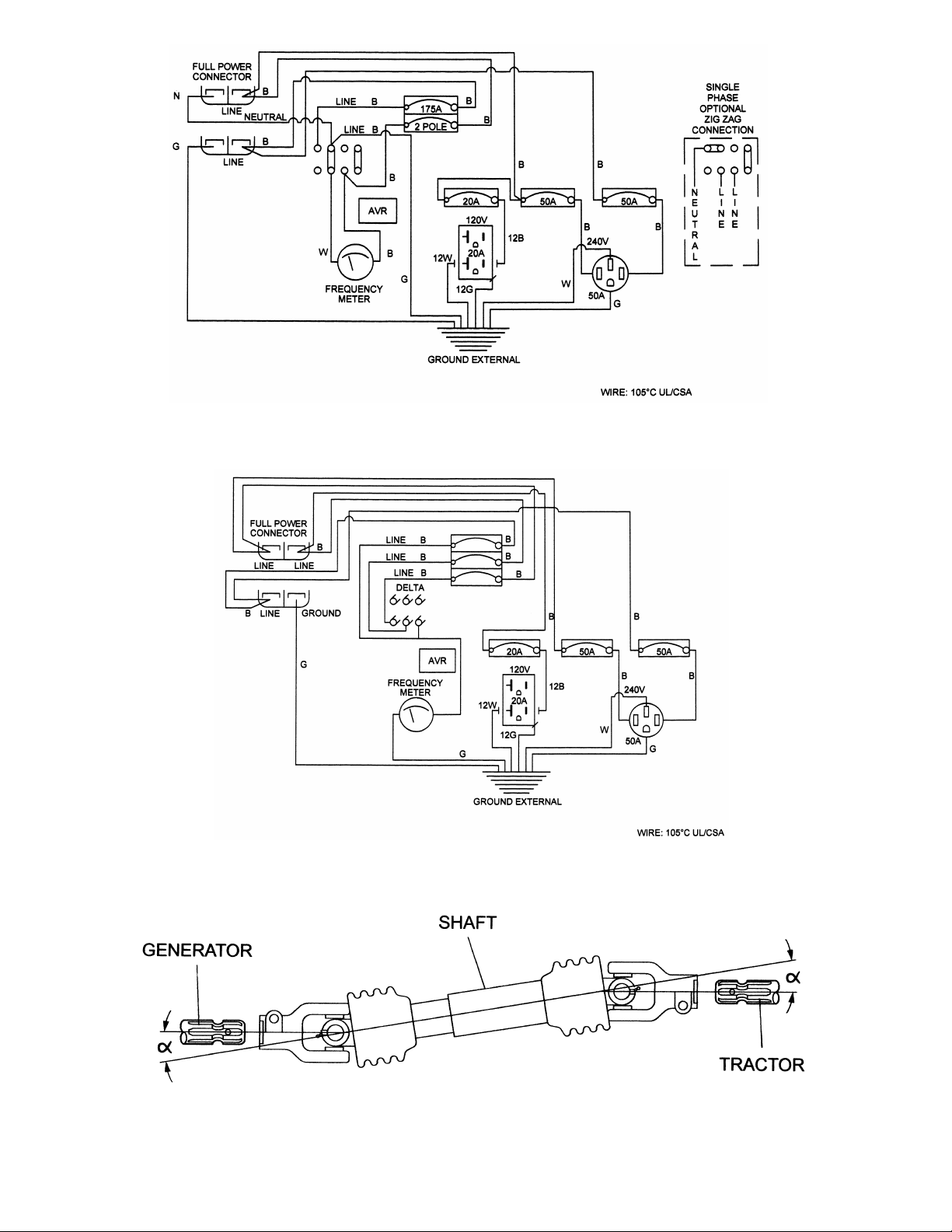
Wiring Diagrams
See figure 8 for PTO 15/12
See figure 9 for PTO 30/25
See figures 10 and 10A for all other
PTOs
Typical Installation
See figures 5, 6 and 7 for all models.
Shaft Installation
See figure 11 for
all models. It is
strongly recommended to keep the
angle of the shaft within 10 degrees
from the tractor PTO and generator
gear box. Do not operate over 540 RPM.
A three point hitch requires a short
shaft and a two-wheel trailer and
ground mounting requires a long shaft.
These optional shafts can be ordered
from your local dealer. Keep guards in
place at all times.
Gear Box
The gear box is
a self contained
helical gear unit. It has a glass
inspection plate. Be sure to check
before using the generator that the
gear oil is at the fill line. Use SAE 90
gear oil. DO NOT overfill the oil or
leaks may occur. The fill location is at
the top of the gear box, inspection
plate is on the side of the gear box
and the drain plug is located on the
bottom of the gear box. This gear box
is not to be serviced in the field. All
gear boxes have been filled with gear
oil at the factory. The cone guards must
be in place at all times.
Parts Explosions
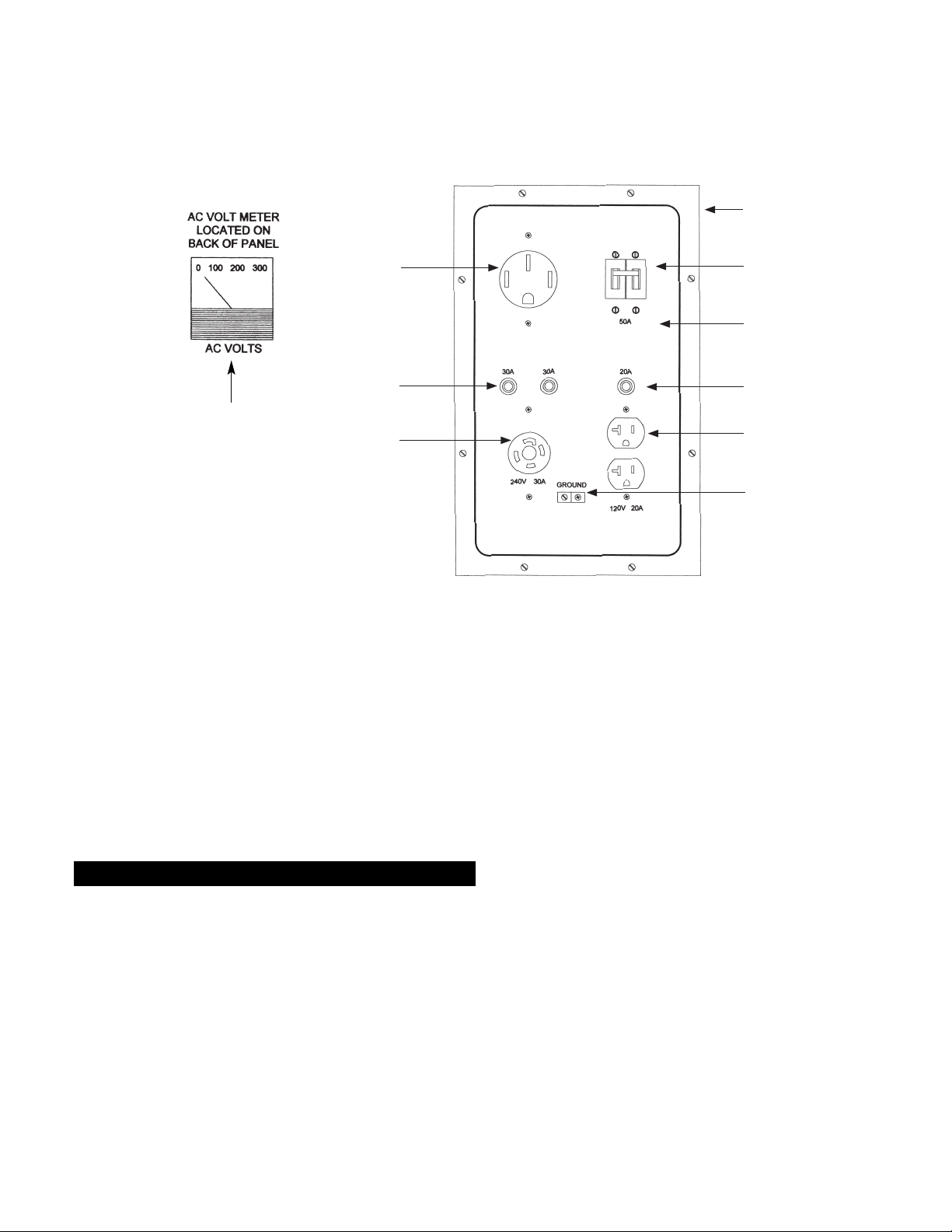
See figure 12 and13 for PTO 15/12
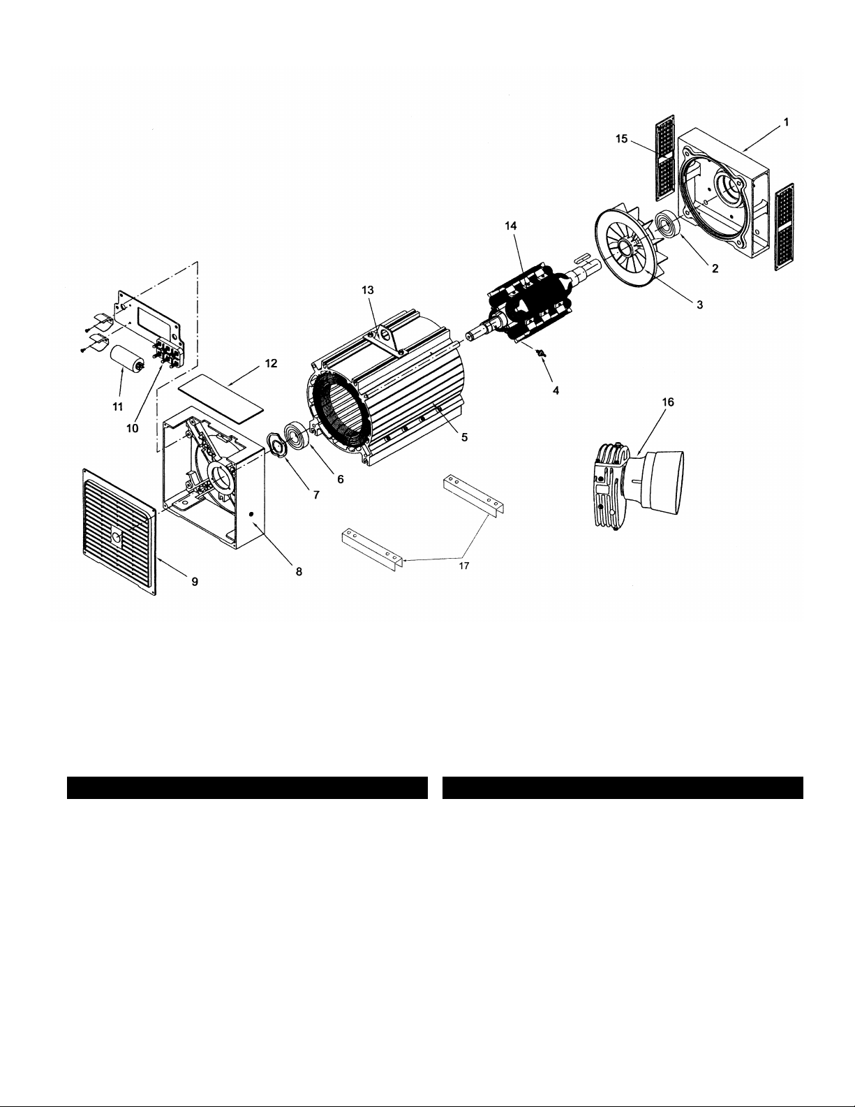
See figure 14 and 15 for PTO 30/25
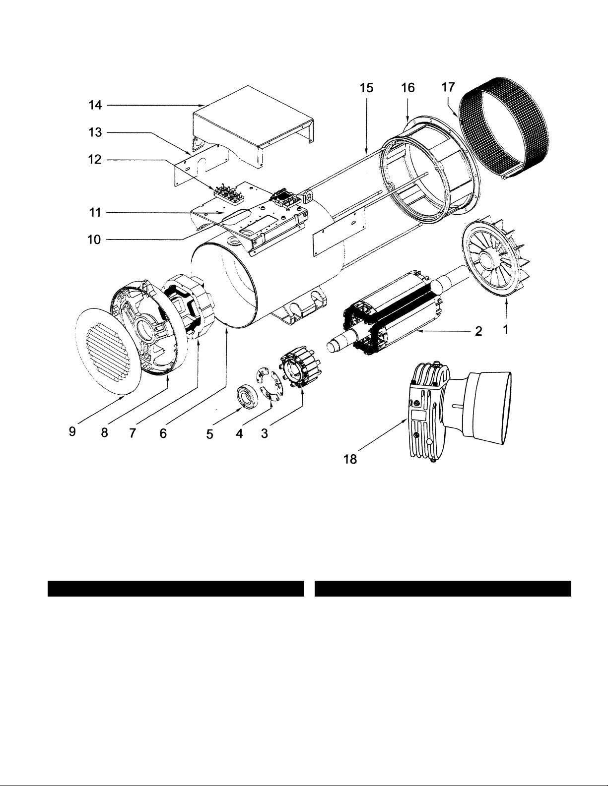
See figure 16 and 17 for PTO 40-1,
PTO 50-1, PTO 65-1, PTO 75-1,
PTO 55-3, PTO 70-3, PTO 90-3
Maintenance
It is recommended to lubricate the
shaft with a lithium base grease. In the
winter with freezing conditions, the
PTO shaft should be greased with a
brush to avoid sticking and freezing.
Before using the generator, be sure to
clean the generator and remove dirt
etc. Barns may contain a lot of
moisture, dirt and ammonia-type gases
that can lead to corrosion of copper
wire. Store this unit in a clean area. Let
the generator cool down completely
before placing any protective cover
over the generator.
To maintain
your generator
under warranty, you must use original
factory parts. Use of non factory
original parts will void the warranty
and the manufacturer does not accept
any claims for property damage, injury,
death or any other damages caused by
the non factory authorized parts.
The gear box oil should be changed
every 250 hours of operation, the shaft
should be lubricated with each use, and
the generator should be tested at least
every 3 months.
4
Page 5
5
Figure 1 – Concrete Mounting
Figure 3 – Two Wheel Trailer 3403 (Optional), Weight 175lbs., Tires P175/80R13 M+S(14” Hub)
Figure 2 – Concrete Mounting Dimensions
MMOODDEELL AA BB CC DD EE
PTO 15/12 18.0 (457) 9.92 (252) 13.625 (346) --- 21.0 (533)
PTO 30/25 22.0 (559) 13.8125 (351) 19.0 (483) --- 27.0 (686)
PTO 40-1 22.0 (559) 13.38 (340) 12.2 (310) 16.9 (429) 27.0 (686)
PTO 50-1 22.0 (559) 13.38 (340) 12.2 (310) 16.9 (429) 27.0 (686)
PTO 65-1 22.0 (559) 13.38 (340) 12.2 (310) 16.9 (429) 27.0 (686)
PTO 55-3 22.0 (559) 13.38 (340) 12.2 (310) 16.9 (429) 27.0 (686)
PTO 70-3 22.0 (559) 13.38 (340) 12.2 (310) 16.9 (429) 27.0 (686)
PTO 75-1 26.0 (660) 15.9 (406) --- 13.7 (347) 24.0 (610)
PTO 90-3 26.0 (660) 15.9 (406) --- 13.7 (347) 24.0 (610)
PTO 100-3 26.0 (660) 15.9 (406) --- 13.7 (347) 24.0 (610)
54
28
79.5
49
TRACTOR
HERE
Page 6
6
Figure 5 – Isolation Switch
Figure 4 – Three Point Hitch 3418 (Optional), Weights 92lbs.
33.5
24.5
38.5
Page 7
7
VARIOUS LOADS
ON GENERATOR
UTILITY LINES
L N L
ELECTRIC METER
MAIN CIRCUIT BREAKER PANEL
VARIOUS LOADS
(NOT ON EMERGENCY GENERATOR)
POWER RETURN LIGHT
ISOLATION SWITCH
(SHOWN IN NORMAL POWER FEED)
VARIOUS LOADS
(NOT ON EMERGENCY GENERATOR)
L
N
L
GENERATOR
Figure 6 – Selected Isolation
Figure 7 – Total Isolation
UTILITY LINES
L N L
ELECTRIC METER
CIRCUIT BREAKER PANEL
VARIOUS LOADS
POWER RETURN LIGHT
ISOLATION SWITCH
(SHOWN IN NORMAL POWER FEED)
L
N
L
GENERATOR
VARIOUS LOADS
Page 8
8
Figure 8 – Wiring Diagram for Model PTO 15/12
Figure 9 – Wiring Diagram for Model PTO 30/25
Page 9
9
Figure 10 – Wiring Diagram for Single Phase Models PTO 40-1, PTO 50-1, PTO 65-1
(PTO 75-1 not shown and does not have a circuit breaker)
Figure 11 – Shafts 3397 (long) 57”-67” and 3421 (short) 37”-50”
(Length Dimensions are end of hub to end of hub. 1 3/8” 6 spline both hubs)
Figure 10A – Wiring Diagram for Three Phase 240V, Delta Models PTO 55-3, PTO 70-3,
(PTO 90-3 and PTO 110-3 not shown do not have a circuit breaker)
Page 10
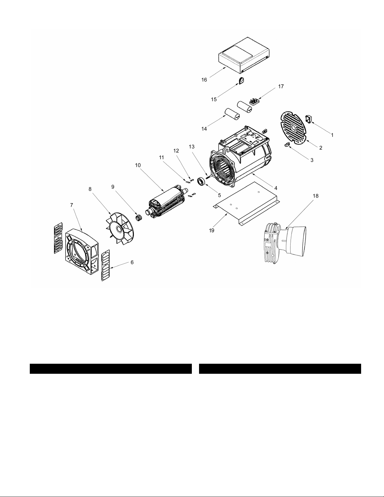
Figure 12 – Parts Explosion for PTO 15/12
10
Repair Parts List for Model PTO 15/12
Item Part No. Description Quantity
1 3344 Rotor Screw Cover 1
2 3342 End Cover 1
3 3282 Grommet 2
4 3346 Stator 1
5 2615 Ball Bearing 52 mm 1
6 3330 Fan Guard 2
7 3328 Fan Bracket 1
8 3332 Fan 1
9 3349 Fixing Ring 1
10 3336 Rotor 1
Item Part No. Description Quantity
11 3190 Diode 2
12 2603 Varister 2
13 3341 Rotor Screw 1
14 1135 Capacitor 35 mf 1
15 3670 Bushing 1
16 3281 Top Cover 1
17 3184 Terminal Strip 1
18 3382 Gear Box Transmission Car 3P 1
18 3383 Safety Cone 1
19 3168-B Base Plate 1
Page 11
11
23
Figure 13 – Parts Explosion for PTO 15/12
Item Part No. Description Quantity
20 3506 Receptacle 50 A, 240 V 1
21 1112 Circuit Breaker 30 A 2
22 1101 Receptacle T/L 30 A,240 V 1
23 3378 Control Box Back 1
24 3015 Circuit Breaker 50 A, 2 Pole 1
25 3377 Front Panel 1
26 1069 Circuit Breaker 20 A 1
27 1011 Receptacle Duplex 20 A, 120 V 1
28 1024 Ground Lug 1
29 2024 Volt Meter 1
29
20
21
22
24
25
26
27
28
Page 12
12
Figure 14 – Parts Explosion for PTO 30/25
Item Part No. Description Quantity
1 3359 Bracket PTO Side 1
2 3361 Ball Bearing 90 mm 1
3 3362 Fan 1
4 3363 Diode 1
5 3356 Stator 1
6 3364 Ball Bearing 80 mm 1
7 3365 Spring Washer 1
8 3368 Bracket (Control Box Side) 1
9 3355 Cover 1
10 3184 Terminal Strip 1
Item Part No. Description Quantity
11 1134 Capacitor 30 mf 2
11 3217 Capacitor 40 mf 1
12 3355-T Top Cover 1
13 3318-LH Lifting Hook 1
14 3357 Rotor 1
15 3358 Fan Guard 2
16 3383 Safety Cone 1
16 3381 Gear Box M5 1
17 3360 Channel 2
Page 13

13
Item Part No. Description Quantity
18 2024 Volt Meter 1
19 3369 Circuit Breaker 100 A, 2 Pole 1
20 1101 Receptacle T/L 30 A, 240 V 1
21 1112 Circuit Breaker 30 A 2
22 1069 Circuit Breaker 20 A 1
23 1011 Receptacle Duplex 20 A, 120 V 1
24 1024 Ground Lug 1
25 3375-F Front Panel 1
26 3379 Connector (Assembly of 2) 1
27 3379 Connector Male loose (2) 1
28 3380 Connector Handle 1
Figure 15 – Parts Explosion for PTO 30/25
18
26
27
28
19
20
21
22
26
23
24
25
Page 14
14
Figure 16 – Parts Explosion for PTO 40-1, PTO 50-1, PTO 65-1, PTO 75-1, PTO 55-3, PTO 70-3, PTO 90-3, PTO 110-3
Item Part No. Description Quantity
1 3655 Fan 1
2 3654 Rotor 1
3 3653 Exciter Armature 1
4 3652 Diode Bridge with Diodes 1
5 3671 Ball Bearing 6312.2RS 1
5A 3672 Ball Bearing 6309.2RS 1
6 3649 Stator 1
7 3651 Exciter Stator 1
8 3647 Bracket (Non PTO Side) 1
9 3673 End Cover 1
Item Part No. Description Quantity
10 3656 Automatic Voltage Regulator 1
11 3660 Mounting Plate Control Box 1
12 3648 Terminal Strip 1
13 3659 Side Panels 2
14 3646 Top Cover 1
15 3657 Stator Thru Bolts 4
16 3650 Fan Bracket 1
17 3658 Fan Guard 1
18 3662 Gear Box transmission M7, M9 1
18 3383 Safety Cone 1
Page 15
15
27
19
24
25
23
22
2120
26
Item Part No. Description Quantity
19 3661 Connector Cover 1
20 3506 Receptacle 50 A, 240 V 1
21 2883 Circuit Breaker 50 A, 1 pole 2
22 1069 Circuit Breaker 20 A 1
23 3673 Front Cover 1
24 1011 Receptacle Duplex 20 A, 120 V 1
25 1024 Ground Lug 1
26* 3512 Circuit Breaker 175 A, 2 Pole 1
27 3479 Frequency (Hertz) Meter 1
28** 3379 Connector Male Loose (2) 1
29** 3380 Connector Handle 1
Item Part No. Description Quantity
* 3569 PTO 40-1 125A, 2 Pole 1
3570 PTO 50-1 175A, 2 Pole 1
3571 PTO 65-1 225A, 2 Pole 1
3572 PTO 55-3 150A, 3 Pole 1
** 3379 and 3380 Used on PTO 40-1,
PTO 50-1 and PTO 55-3 1
** 350A Used on PTO 65-1,PTO 75-1,
PTO 70-3, PTO 90-3 and PTO 110-3 1
Figure 17 – Parts Explosion for PTO 40-1, PTO 50-1, PTO 65-1, PTO 75-1, PTO 55-3, PTO 70-3, PTO 90-3, PTO 110-3
29
28
* Model PTO 50-1 shown
(Models PTO 75-1, PTO 90-3 and PTO 110-3, do not come with a main line circuit breaker. customer supplied)
SINGLE PHASE
THREE PHASE
LINE
LINE
LINE
NEUTRAL
LINE
LINE
NEUTRAL
GROUND
Page 16

16
Adjusting Voltage for PTO’s
All PTO’s with 12 wire
units feature an
automatic voltage regulator that will
maintain +/- 1 ½% voltage regulation.
The voltage regulator is preset at the
factory for the required voltage. If a
change in voltage is required, the
frequency meter MUST be connected to
one line (hot) wire and to the neutral
connection for the meter to function.
On a three phase 240 volt series delta
connection, there is no neutral. For
neutral conncection you must use the
center tap(CT) adjacent to the line
connection you choose. With the
frequency meter operating at 60 hertz
(50 hertz for 50 hertz operation and the
jumper installed) you can increase or
decrease the voltage by simply adjusting
the Phillips screw marked VOLTS on the
automatic voltage regulator.
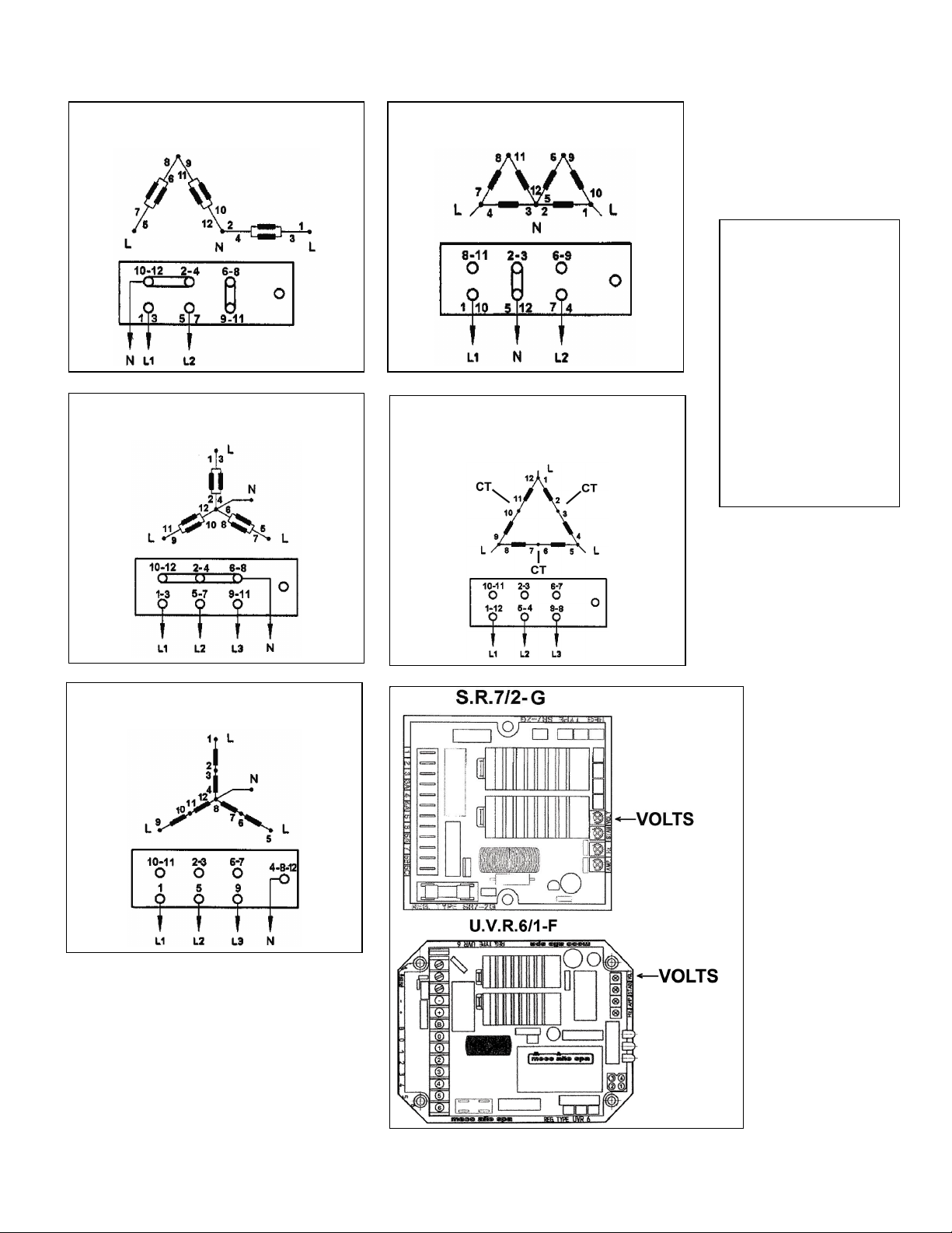
See connections/reconnections page
The generator must
be operating at the
proper speed (RPM) before and while
adjusting the voltage regulator. Turn the
VOLTS adjusting screw very slowly stop
and wait 2 or 3 seconds and read the
voltage from one of the lines and
neutral connection (note that on the
three phase 240 volt series delta
connection there is no neutral so you
must go to the center tap as a neutral.
Adjust the voltage up or down by
turning the VOLTS clock wise or counter
clock wise. Once the voltage is adjusted,
do not adjust any of the other Phillips
screws on the automatic voltage
regulator. Refer to the re connection
chart if you are changing voltages. Near
the automatic voltage regulator are the
main power terminals of the generator.
If you make contact with the main
terminals, serious injury and death will
occur. These adjustments MUST be done
by a licensed electrician or technician
familiar with high voltage equipment.
This is NOT a do it yourself activity.
From the automatic voltage regulator
terminal 4 a green wire always goes to
stator lead wire 3. From the automatic
voltage regulator terminal 5 a black
wire always goes to stator lead wire 4.
This applies to single and three phase
units both 50 and 60 hertz and any
voltage combination. On 60 hertz
versions, single and three phase and any
voltage combination,
there is a small brass jumper connected
on the automatic voltage regulator
between terminal 5 and terminal 6. For
50 hertz operation, this jumper is
removed.
Adjacent to the automatic voltage
regulator is the radio suppressor on
some models. The lead wires from the
radio suppressor are always red and
must go to the stator leads wires 5, 7, 9
and 12 on any version in single or three
phase., 50 or 60 hertz and any voltage
combination. Some leads may be on
the same terminals as other depending
on the various phase and voltage
combinations.
Changing voltage will change the
amperage output of the generator. The
circuit breaker should be changed
accordingly.
OPERATING GENERATOR
SHAFT SPEED
For 60 hertz
operation the
generator shaft speed of 1800 RPM
must be continuously maintained. The
operating speed range is 1700 RPM to
1900 RPM for 60 hertz. Shaft speed of
the gear box connected to the
generator is either 540 RPM or 1000
RPM depending on the model. Slightly
lower gear box speed(about 520 RPM
for the 540 RPM on/or 970 RPM for the
1000 RPM unit is acceptable, the
frequency meter at 60 hertz is how to
determine proper speed. These are NOT
variable speed generators.
GUARD FOR PULLEYS, BELTS
AND COUPLINGS
All rotating
equipment MUST
be equipped with guards to prevent
contact with rotating shafts, pulleys,
belts and couplings. The customer is
responsible for installing the
appropriate guards. Serious personal
injury or death could result without
proper guards in place while the
generator is in operation.
Page 17
17
PTO Series Connections/RE Connections 60 Hertz 12 Wire Generators
SINGLE PHASE 120/240 VOLTS
PARALLEL ZIG ZAG
THREE PHASE 120/208 VOLTS
PARALLEL STAR
SINGLE PHASE 120/240 VOLTS
DOUBLE DELTA
THREE PHASE 240 VOLTS
SERIES DELTA (NO NEUTRAL)
CT CENTER TAP
L1 = LINE
L2 = LINE
L3 = LINE
N = NEUTRAL
CT = CENTER TAP
DO NOT USE
OTHER
CONNECTION
TERMINALS
THREE PHASE 277/460/480 VOLTS
SERIES STAR
FOR 50 HERTZ CONNECTIONS,
CONSULT THE FACTORY.
VOLTAGE
REGULATORS
Page 18

ORDERING PARTS
Instructions For Ordering Repair Parts
18
For parts or service, contact either the factory or the dealer or distributor from whom you purchased this
equipment for the name of the nearest authorized service station.
1. To avoid errors or delay in filling your parts order, please furnish all information requested and always
refer to the nameplate on your unit by giving the model and serial number.
2. Do not order by reference number or group number. Always use part number and description.
3. Give the part number, description and quantity needed for each item.
4. State definite shipping instructions. Any claim for loss or damage to your unit in transit should be filed
promptly against the transportation company making the delivery. Shipments are complete unless the
packing list indicated items are back ordered.
5. FOR SERVICE OR PARTS CONTACT THE FACTORY AT:
Wanco/Voltmaster
Phone 800-730-3927 Fax 303-427-5725
5870 Tennyson Street, Arvada, Colorado 80003
.
FIVE/ONE YEAR LIMITED WARRANTY- PTO SERIES
Five year limited warranty on parts and a 1year limited warranty on labor.
This warranty extends to the original purchaser only. The generator sold is warranted to the original
purchaser for a period of five (5) years for parts only and one (1) year for labor only from the original
purchase date. The manufacturer warrants the generator sold to be free from defects in material and
workmanship if properly installed, serviced and operated within nameplate rating under normal
conditions according to the manufacturer's instructions.
Disclaimers
This warranty does not apply to any items which must be repaired or replace
have been subject to misuse, negligence, accident or which have been repaired, altered by others
outside of the manufacturer's factory unless authorized in writing by the manufacturer. Under no
circumstances will the manufacturer be liable for any or consequential damage or expense of any kind,
including loss of profits nor the fitness of the product for any specific application or particular purpose.
Any implied warranties are limited in duration to the above one (1) year period. Some
limitations on how long an implied warranty lasts, so the above limitation or exclusion may not apply to
you. This warranty gives you specific legal rights, and you may also have other rights, which vary from
state to state.
d due to normal wear, which
states do not allow
Performance
The manufacturer's obligation under this warranty is limited to correcting without further charge at its
factory or authorized service station any part or parts which shall be returned transportation charges
prepaid, and which upon examination shall disclose to the manufacturer's satisfaction to have been
originally defective. Other than transportation charges, no charge will be made for such repair
adjustment and /or replacement. This remedy is expressly in lieu of all other remedies, and is the
purchaser's sole and exclusive remedy hereunder.
 Loading...