

Installation Guide
Voltex Indoor 360°Motion Sensor - IP43 - 2 relay
© Voltex Electrical 2016. All Rights Reserved.
®
1. Power: 220-240V~ 50Hz.
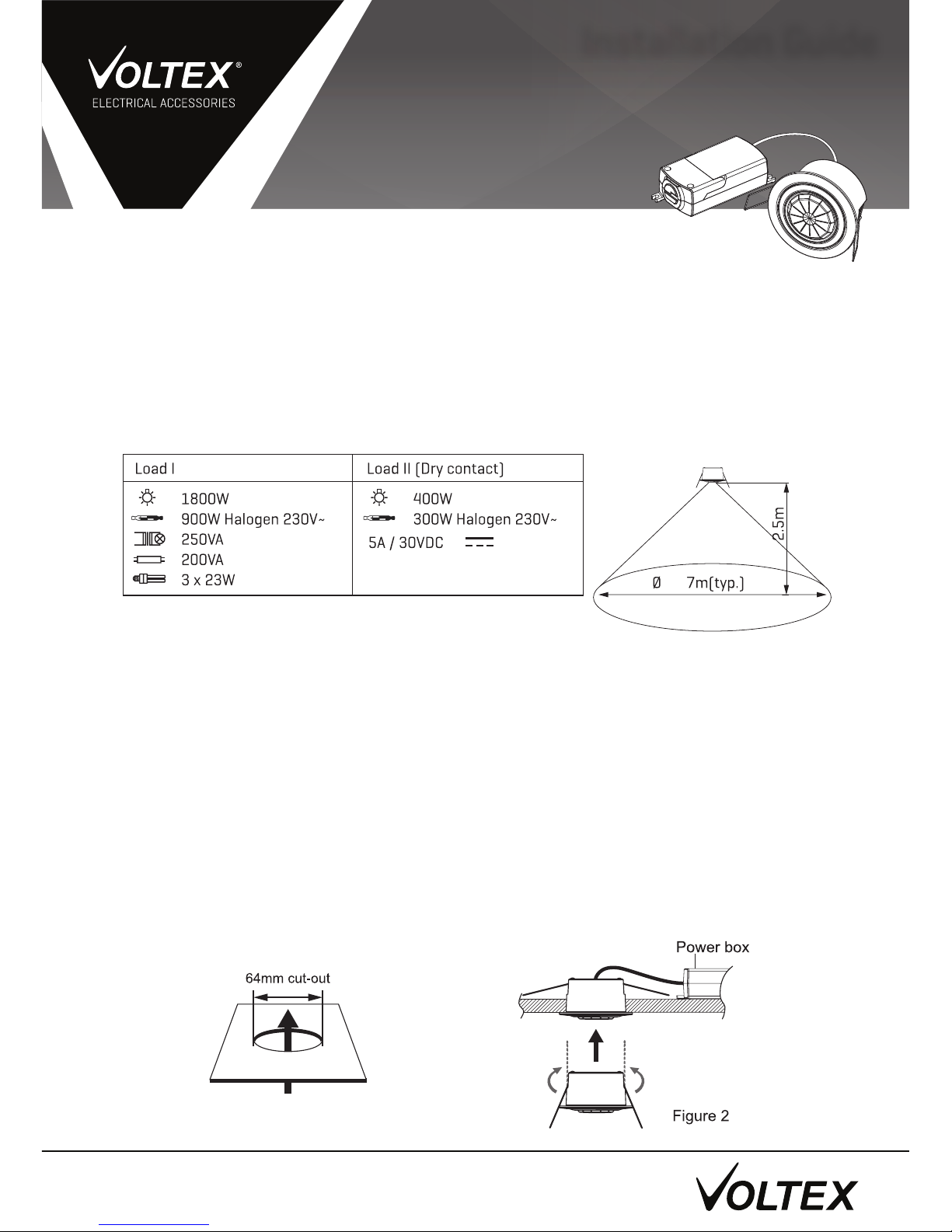
2. Range of detection: 360°, 7m(typ.) diameter at 2.5m height, 20°C. (Figure 1)
3. TIME 1 adjustment: , 30 sec, 1 min, 5 min, 10 min and 30 min, maximum=TEST mode.
TIME 2 adjustment: 10 sec, 30 sec, 1 min, 2 min, 3 min, 5 min, 10 min and 15 min.
4. Lux control: Adjustable “Light level” sensing from 5 Lux to 1000 Lux, maximum=LUX
Memory.
5. Load:
1. Turn OFF power at the circuit breaker or fuse.
2. Determine the best location for the sensor.
3. Drill a 64mm diameter hole in the ceiling.
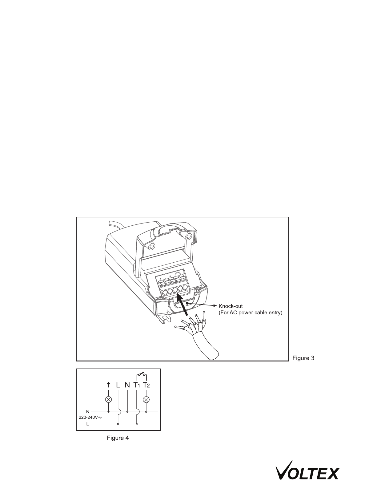
4. Connect as shown in wiring diagram. (Figure 4)
5. Insert the power module into the ceiling first and then fix the sensor with metal spring.
(Figure 2)
Specifications:
Installation:
Warning: This equipment must be installed only by a qualified electrician. Installation must
follow local building codes as well as the instruction contained in this manual. Turn off power
at circuit breaker or fuse box, to make sure power is off before installation. If you have
any doubts about the installation procedure, please consult a professional technician.
Determine the best location for the sensor. Install the sensor at least 1 metre away
from any light fittings and HVAC ducts or vents. The sensor is to be mounted on ceiling.
(Figure 2)
(IP43 from below, as installed)
Connection to the power supply:
1. Note: This sensor
must be installed according to local Wiring Regulations and Code of
Practice.
2. Note: Make sure that the power wiring comes from an external 10A miniature circuit
breaker for short circuit protection.
3. Ensure the supply is disconnected at the distribution board before doing with the electrical
wiring. If any doubt, check the wire with a voltage tester.
4. Study the wiring diagram below before making any electrical connections. Incorrect
wiring of the unit could destroy the sensor.
5. Strip the cable and connect the wires to terminal block. (Figure 3)
6. Connect Brown wire from the supply circuit (incoming active/phase) to the active terminal
(L).
7.
8.
9. Contact T1 and T2 are Dry contacts.
10. Switch on the power and the detector will commence a 60 second warm-up period.
Connect Blue wires (neutrals) from the supply circuit and lamp circuit to the Neutral
terminal (N).
Connect the lighting load ("Time 1" Output) to terminal. ( ).
↑
Wire according to Figure 4, for 240 V output on "Time 2" Output
© Voltex Electrical 2016. All Rights Reserved.
®
Cable Size - Min: 1.0mm² Max: 4.0mm²

TIME 1: The time can be set variably from , 30 sec, 1 min, 5 min, 10 min and 30 min.
Timer starts counting from the latest detected movement. While there is still movement in
the detecting area, the
red LED indicator and lighting will remain on and the timer will keep
resetting. (Figure 6)
PULSE ( ): If the arrow is pointing to “pulse” ( )
© Voltex Electrical 2016. All Rights Reserved.
®
Adjustments:
• The sensor reacts to any motion in the detecting area, and to the settings of Lux.
• When the sensor is activated, the LED and lighting will be turned on for 1 second and off for
9 seconds as a complete period before receiving another detection.
TEST: If the arrow is pointing to “TEST”
• The Lux setting is deactivated.
• When the sensor is activated by motion, the LED and the lighting will be turned on for
3 seconds.
TIME 2: The time can be set variably from 10 sec, 30 sec, 1 min, 2 min, 3 min, 5 min, 10 min
and 15 min. Timer starts counting from the latest detected movement. While there is still
movement in the detecting area, the red LED indicator and lighting will remain on and the
timer will keep resetting. The LUX setting is ignored. (Figure 7)
LUX: The adjustment controls the sensitivity to the background light level at which the
detector will operate automatically. It may be set to any level between 5 Lux and full daylight.
"Time 1" Output will operate when it senses motion and the ambient light is at or below the
set level. (Figure 8)
NOTE: "Time 2" Output operates regardless of LUX setting or ambient light level.
LUX Memory ( ): If the arrow is pointing to “lux memory” ( ), the sensor will memorize
the ambient light level, from 5 lux to 200 lux as an on/off threshold. (Figure 8)
1.
2.
3.

®
Voltex Electrical 2016. All Rights Reserved.
P: 1300 722 275 E: sales@voltexelectrical.com.au
Australia
P: 0800 55 66 33 E: sales@voltexelectrical.co.nz
New Zealand
www.voltexelectrical.com.au
www.voltexelectrical.co.nz
Voltex Electrical
1. After connection to
mains power, 60 seconds is required to warm up. The LED indicator
and lighting lasts approximately 60 seconds.
2. Walk in front of the detector until the light comes up. This checks the operation of the
detector and the field of view. Under test mode, the LED indicator and lighting will be turned
on for 3 seconds when each movement is detected.
3. Repeat step 2 and adjust the angle of the dome lens until the optimum field of view is
achieved.
4. Turn the Time and Ambient Light (LUX) control to the desired positions.
5. The detector is now in Auto Mode and will operate according to the preset time and ambient
light (LUX) adjustments. LED indicator will keep flashing at stand-by mode. Once activated,
LED indicator and lighting will remain on untill timer out.
6. To turn the lights Off: Turn the power switch off or unplug the AC plug.
1. Unit will not function at all/Lights won’t come on
- Check wiring to make sure that you have correct AC power at the unit.
- Check the wiring from the unit to the source of power to make sure you have wired the unit
correctly.
- Check the ambient light control to see if it was set at your desired level.
2. Detector clicks but does not work
- Check if lamps are broken.
- Check if lamps are tight in lampholders.
3. Lights go on and off quickly
- Ensure light and heat are not being reflected onto the detector. Check for white or reflective
surfaces that may be causing the problem.
- Note the detector is more sensitive in cold weather.
- Make sure the sensor is not installed close to air-conditioner.
- Make sure the Time setting is not at Pulse Mode position.
- Make sure the Lux setting is not at Test Mode position.
4. Lights stay on
- Light bulb sockets may be wired directly to the power source.
- Recheck the wiring diagram.
- Adjust time to minimum, and ensure unit is firmly fixed to a solid object with no moving
branches etc. in field of view.
- Ensure detector is not being activated by stray moving heat sources such as heating outlets.
5. Detector goes on under windy and rainy condition
- Adverse weather conditions and temperature changes can result in unwanted activations.
- This can be minimized by mounting in a protected location.
6. Maintenance and repair
- Do not attempt to repair as this could invalidate warranty or result in personal injury.
- Clean detector lens and outside casing with damp cloth.
Initial set up and operation:
Trouble Shooting:
 Loading...