


Supercam1 Weatherproofing IP54 (outdoors and indoors)
Overall size 3.5” W x 4.3” H x 4.5” D
Audio signal 1V pk-pk into 47K Ω
Operating temperature -10ºC to +40
ºC
Power Supply Input Voltage 220V/240V ac 56/60 Hz
Output Voltage 12V dc
Output Current 300mA (max)
Weatherproofing IP30 (indoor use only)
2 Metre Cable type 6 core alarm cable
Camera Lead Connectors 6 pin mini-DIN socket
18 Metre Lead Cable type 6 core alarm cable
Connectors 6 pin mini-DIN socket
21 pin scart plug
6 way RJ11 plug
2.1mm power plug
INSTALLATION
INSTRUCTIONS
Churchill Way , Lomeshaye Industrial Esate, Nelson, Lancashire BB9 6R T, England
T el: (01282) 695500 Fax: (01282) 695511 Helpline: 09066 191 133*
Email: sales@voltek.co.uk Web site www.voltek.co.uk
*Helpline Calls Cost 60p/min Open 9am to 5pm Mon to Fri
Specifications subject to change without notice. Ó2004 Voltek Automation Ltd. Issue 2.3
CAMERA SPECIFICATIONS (continued)
SUPERCAM 1
CT120
External B&W Camera with PIR Sensor
CT121
External Colour Camera with PIR Sensor
CT122
External Day Night Camera with PIR Sensor and IR LEDS
Colour during the Day switching to B&W at Night
IR LEDs switching on at night to aid night vision
The SuperCam1 is a combined camera and PIR detector with a built in microphone
providing you the ability to ‘see’ outside your property using your own TV set. The
Keypad Remote Control supplied with the camera will sit neatly on top of your TV or
VCR allowing you to monitor and control the system.
• Black & white, Colour or Day/Night camera with wide viewing angle.
• Built-in high quality PIR sensor for detecting intruders / visitors.
• Automatically switches the TV to the Camera picture when movement is
detected.
• Pre-connected 20 metre lead. Extendable up to 100 metres.
• Will connect to any UK television or video recorder that has a SCART socket,
making the installation very simple.
• For a multiple TV installation the SuperCam will connect into an aerial system
using the optional RF Modulator CT210.
• Connect up to 4 cameras using the 4- Way Switcher Unit - CT200.
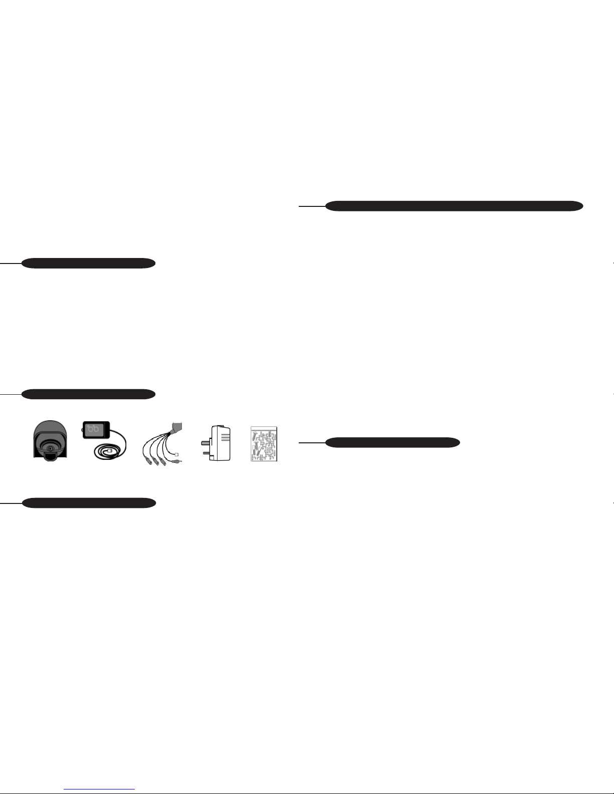
Please check and identify all the parts before proceeding with the installation
.
Before starting the installation we recommend that you temporarily connect the
SuperCam1 to your TV or VCR to help determine the best position.
The SuperCam1 will connect to a spare Scart socket (also known as a Peritel or
Euroconnector) on your TV or VCR. If you do not have a spare scart socket you will
require a CT210 RF Modulator which will allow you to connect the SuperCam1 to
the aerial input of your TV or VCR.
IF THE SCART SOCKET IS IN USE OR THE PICTURE IS T O BE VIEWED ON MULTIPLE
TVS:
CT210 Wideband RF Modulator
This unit will allow the SuperCam1 to be connected to the aerial input of your TV or video
recorder. This means that the SuperCam1 can be connected to your TV even if the scart
socket is occupied and it will also enable viewing on other TV sets in the property with the
use of an aerial distribution amplifier.
IF THE CABLE SUPPLIED IS TOO SHORT:
CT251 15 metre Extension lead
This 15 metre lead will simply plug in between the supplied lead and the camera head lead
adding to the distance that the camera can be installed away from the TV. Up to 5 extension
leads may be used with one camera enabling it to be sited up to 95 metres away from the
TV.
IF YOU REQUIRE THE CAMERA T O ACTIVATE YOUR VIDEO RECORDER AUTOMATICALLY:
CT220 Video Activator
This unit plugs into the SuperCam1 lead and when it is switched into the record mode it will
automatically activate the record facility of most domestic VCRs on receiving an alarm
signal from the SuperCam1s PIR for a period of 30/60 seconds.
IF YOU REQUIRE A DATED RECORD OF AN EVENT :
CT230 Time and Date Generator
This unit will plug in between the scart plug of the superCam1 lead and video recorder and
superimpose the actual time and date on to any recording of events as they happen.
If you have any questions about our products or if you have difficulty in locating
accessories for the SuperCam1 please call our HELPLINE on 09066 191 133*.
SuperCam 1 Operating voltage 11 - 13V dc
Current consumption 80 mA (approx.) @12Vdc
Camera type B&W 1/4” CMOS / Colour 1/3” CMOS
Lens B&W 3.6mm / Colour 4.3mm
Viewing Angle 78
o
viewing angle
Resolution 300 TV lines
Minimum illumination (CT120) 2 lux
(CT121) 4 lux
(CT122) 2 lux (0 Lux IR on 3 metres MAX)
Video signal (CT120) CCIR 1V pk-pk into 75 Ω
(CT121) PAL format
(CT122) PAL format
SYSTEM CONTENTS
KEY PRODUCT FEATURES
Keypad
Remote
Control
Power
supply
20 Metre
Scart lead
Fixing Kit
GETTING THE BEST FROM YOUR SUPERCAM 1 (continued)
CAMERA SPECIFICA TIONS
Page 1 Page 6
SuperCam1
Camera
Head
INSTALLING THE SUPERCAM

The sounder can be switched off by pressing
the sounder button. An LED on the Keypad
Remote Control indicates if the sounder is
armed or disarmed.
Picture Over-ride
When movement is detected, the television
picture will automatically switch to the
camera channel to show you the person
outside your property. (Please note that this feature only works when the
SuperCam1 is directly connected to the Scart socket on your TV set). The camera
picture will stay on for 15 seconds after the person has stopped moving, when the
picture will revert back to the previous channel.
The picture over-ride can be
switched off by pressing the picture over-ride button on the keypad. An LED on the
keypad remote control indicates if the Picture Interrupt is armed or disarmed.
This product has a 12 month manufacturers warranty. In the unlikely event that you
encounter a problem with this product, it should be returned to the place of
purchase.
USING THE SUPERCAM1 (continued)
WARRANTY
GETTING THE BEST FROM YOUR SUPERCAM 1
FOR MORE THAN ONE CAMERA:
4-Way Camera switcher - CT200
This will allow switching of video and audio signals from up to 4 SuperCam1s with
an output that can be connected by the scart socket to your existing TV or video
recorder. Simple plug in connectors allow for quick installation. The switcher offers
manual or automatic mode switching between the inputs, In the automatic mode
the length of time an individual camera picture remains on screen (dwell time) is
adjustable between 2 and 30 seconds.
CONNECTION METHOD 2
CONNECTION METHOD 1
Page 2Page 5
There are two connection methods shown, choose the method that suits your
requirements the best.
If you are not using a VCR, connect the SuperCam1 to your TV as shown.
T o view the SuperCam1 picture ;
1. Switch on the TV and power to the SuperCam1.
2. Select the AV channel on your TV. See HOW TO SELECT THE AV INPUT if
you are not sure how to do this.
If you are using a VCR and have a spare Scart socket on the VCR connect the
SuperCam1 as shown.
To view the SuperCam1 picture ;
1. Switch on the TV, VCR and power to the SuperCam1.
2. Select the VCR channel on your TV. This is the channel you normally use for
watching a video tape

3. Select the AV input on your VCR . See HOW TO SELECT THE AV INPUT if you
are not sure how to do this.
Please note that the picture interrupt feature will not work when connected in this
method, the SuperCam1 must be connected directly to the TV for this feature to
work.
To connect more than one camera to your TV/VCR you will require the 4-way
switcher Unit - CT200 (see page 6).
When you connect the SuperCam1 to a Scart socket NO TUNING is required.
Simply press the appropriate button on the TV or VCR to see the picture.
The button will look like one of the following ;
Note : some models of TV use channel 0 or Input Select button for the AV input. See
the television instruction for further details
The SuperCam1 is suitable for indoor or outdoor use. Please bear in mind the
following points when choosing a mounting position.
• The camera must be positioned so that it will not point directly into the sun
(sunrise and sunset) or any bright light, as this may cause damage to the
camera.
• Avoid viewing areas where half the area is in bright sunlight and the other
half is dark, such as in the shadow of a building. All types of cameras have
difficulty in ‘seeing’ with such a large lux level variation.
• The camera will work in low light conditions, but ensure a light, such as a
200W tungsten halogen lamp, is fitted near to the camera for good visibility
at night-time.
• The PIR sensor is at it’s most sensitive when a person moves across the face of
the sensor rather than towards the sensor. This means the person crosses
more detection beams and the PIR sensor is therefore more sensitive.
Maximum detection range is 6 metres.
• Avoid placing the SuperCam 1 close to heater flue outlets, trees or bushes
which may cause a false alarm.
• The camera cable supplied may be extended up to 100 metres. Please bear
this in mind when choosing your siting position.
PLEASE NOTE - THE SUPERCAM PIR SENSOR WILL NOT OPERATE THROUGH
GLASS
You can now check the camera’s view in different positions enabling you to choose
the best position for your property,
When laying the cable, please bear in mind the following points.
a) Keep the camera cable away from other cables where possible to
reduce the risk of picture and audio interference
b) Avoid laying the cable next to anything which runs hot which could
possibly burn the cable.
c) If the cable is run along the ground, a protective covering must be
used to prevent the cable from being damaged.
Viewing The Camera Picture
The method of selecting the camera picture depends upon how the SuperCam1 is
connected to your TV set. Details of selecting the camera picture are given next to
each installation method (see INSTALLING THE SUPERCAM1)
Movement Sounder
When movement is detected by the PIR sensor, the sounder inside the keypad will
bleep to bring your attention to the fact someone is outside your property.
HOW TO SELECT THE AV INPUT
WHERE TO POSITION THE SUPERCAM
MULTIPLE CAMERA INSTALLA TION
COMPLETING THE INSTALLA TION
USING THE SUPERCAM1
Page 3 Page 4
 Loading...