


Churchill Way , Lomeshaye Ind. Est, Nelson, Lancs, BB9 6R T, England
T el 01282 695500 Fax 01282 69551 1 Helpline 09066 191 133*
E-mail sales@voltek.co.uk Website www.voltek.co.uk
*Helpline calls cost 60p/minute. Open 9am to 5pm, Mon to Fri.
Voltek reserves the right to change any product or
specification without notice (c) 2006 Issue2
Page 7
CRS200
Wireless Receiver
INST ALLA TION & USER
INSTRUCTIONS
Compatible with CA240, CA250, CA500, CA500B CTR210, CT220, CT230
2.4GHz wireless technology
Plug ‘n’ Play
Transmits sound and Video from camera to TV
High quality audio and video components for long life
Supports up to 3 cameras
Auto switching between cameras
Alarm output for triggering CT220 VCR Controller
PRODUCT FEATURES
Please check and identify all the parts before proceeding with the installation.
Receiver
P A CKAGE CONTENTS
1 x 12V Reciver
power adaptor
Phono to Phono
Lead
VCA Link Lead
Scart adaptor
Receiver
Operating voltage 12V dc
Current consumption 200mA
Reception frequency 2.41GHz - 2.47GHz (3 channels)
Weatherproofing IP30 (indoor use only)
Operating temperature +2º to 35ºC
Dimensions 140 x 200 x 210mm
General
Approvals CE directive 93/68/EEC
EMC directive 98/336/EEC
Low voltage directive 73/23/EEC
Package size 35 x 130 x 175mm
Package weight 0.4Kg
SPECIFICATIONS
ACCESSORIES
CA240 B&W Camera / T ransmitter
CA250 Colour Camera / T ransmitter
CA500B B&W Camera / T ransmitter
CA500 Colour Camera / T ransmitter
CRP240 / BAT500 Rechargable Battery Pack
CT220 VCR Controller
CT230 Time & Date Generator
CTR210 TV Modulator
Please read these instructions before attempting to operate the product.
WARNING: To prevent fire or shock hazard, do not expose the Receiver / Power
Supplies to rain or moisture.
CAUTION: RISK OF ELECTRIC SHOCK: Do not remove the cover from the power
supply. There are no user serviceable parts inside. Refer servicing to qualified
service personnel.
SAFETY FIRST
Page 1
INSTALLATION
Unpack the Receiver.
Please follow one of the relivent connection methords;
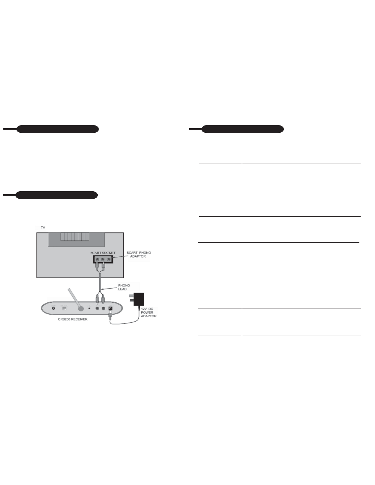
CONNECTION METHORD 1 CONNECTING T O A TV
CONNECTING RECEIVER
The Receiver connection is now complete.
NO TUNING is required, simply select the AV channel on your TV to view the
camera picture. If your not sure how to select the AV channel on your TV you
will need to look up selecting the AV channel in your TV installation instructions.
Page 6
TROUBLESHOOTING
If you are having trouble operating this product, please consult the guide below. If
you still encounter problems then please contact the Voltek helpline on
09066 191 133*
REMEDY
1. Check all connectors and check that the power is
switched on to your receiver and to the camera/
transmitter.
2. Ensure the camera and receiver are set to the correct
channel refer to page 5 for more details.
3. Check the transmitter/camera is within range of the
receiver.
4. Check camera is switched on and the red power on LED
is lit on the camera.
1. Check the receiver is switched on,
2. Check the power adaptor is plugged in an turned on at the
Mains outlet.
3. Check that the TV or VCR is on the correct AV Channel.
1. Check that each transmitter and receiver is within range
and that no large obstructions are blocking the signal,
2. Try repositioning the camera/transmitter or the
receiver to improve the reception quality.
3. If a transmitter is positioned close to the receiver, point the
antenna away from the receiver.
4. Check the lead has been unbundled
5. Check that the lead is not running along side any other
cables.
6. Check if there is any other equipment transmitting on the
2.4GHz frequency nearby.
1. Check that you have a light illuminating the area. (Street
lights
may not be adequate)
2. Check the camera is not pointing at a light.
1. Ensure the volume is turned up sufficiently on the TV .
2. Make sure the sound is within the microphone range.
3. If the unit emits a loud wailing sound try moving the camera
away from the TV.
SYMPTOM
No camera picture
Blank Picture
Interference on the
camera picture
Poor picture at
night.
Audio problems

CONNECTION METHORD 2 CONNECTING TO A VCR
Receiver
DIP switches
SETTING THE DIP SWITCHES
When you receive the receiver, the DIP switch on the rear will have one channel
set in the down position. This represents Channel 1, enabling you to use the
system with one camera. Refer to page 6 of the instructions for location of the DIP
switch.The white part in the diagram represents the switch.
USING ONE CAMERA
Camera
DIP switches
The switch is in
the ON position
when it is in the
down position
The Receiver connection is now complete.
NO TUNING is required, simply select the Video Channel on your TV and the AV
channel on your VCR to view the camera picture. If your not sure how to select the
AV channel on your VCR you will need to look up selecting the AV channel in your
VCR installation instructions.
Page 2
If adding additional cameras to your system you will need to change the DIP
switch to reflect the number of cameras being used.
USING TWO CAMERAS
T o use two cameras, two channels need to be selected on the DIP switch. The
first two channels switches should be in the down position.
Page 5
You can connect a VCR and a CT220 VCR Controller to the CRS200 receiver
allowing you to record the camera picture in the event of an alarm.
Connect the A V cables and CT220 VCR Controller (Not supplied) as shown below .
CONNECTING A CT220 VCR Controller
This product has a twelve month manufacturers parts and labour warranty . In the
unlikely event that you encounter a problem with this product, please telephone the
Voltek helpline on 09066 191 133*. Should the problem not be able to be resolved
over the telephone it should be returned to the place of purchase or direct to Voltek
WARRANTY
*Helpline calls cost 60p/minute. Open 9am to 5pm, Mon to Fri.
IN OUT
12V DC
A
OUT
V
12V DC BEEP
SELECT
VCA
Scart to Phon o
Lead
CRS200 Receiver
SCART SOCKET
Scart to Phon o
Adaptor
Video Recorder
VCA
Link Lead
CT220
VCR Controlle
r

Page 3 Page 4
The 2.4GHz video signals pass easily through your homes interior walls, but the
signal maybe reflected by power wires or plumbing inside the wall. Usually a slight
adjustment of Receiver and / or Camera / Transmitter antenna will improve
reception. Take care not to force the antennas past their lock positions.
The most common source of interference are microwave ovens. Try to avoid mounting the Receiver near a microwave oven or other source of RF interference such as
cordless phones.
USING THE CRS200 VIDEO SYSTEM
Motion detecting cameras
Each camera has a PIR motion sensor. When a camera detects motion an alarm
beeper will sound on the receiver and the receiver will output a signal to trigger a
CT220 VCR controller if installed. The volume control for the bleeper and the VCA
output (CT220 VCR Controller connection socket) is on the rear of the receiver.
Additionally a red light will flash on the camera.
Channels 1&2
Selected
Camera 1
Camera 2
Receiver
Camera
DIP switches
Receiver
DIP switches
Camera 3
USING THREE CAMERAS
Receiver
DIP switches
All Channels
(1,2,3)
Selected
Camera 2
Receiver
Camera 1
Camera
DIP switches
A
OUT
V
12V DC BEEP
SELECT
VCA
Beeper Volume
Adjustmen
t
Antenna
Camera Channel
Dip Switches
12V DC Power
Socket
CT220 VCA
Output
Audio Output Video Output
Manual Mode
In “Manual Mode” individual cameras may be selected. Pressing the button
marked manual on the diagram below will select “Manual” and the LED indicator
will turn red.
Auto Mode
T o select Auto mode press the “Auto” button marked on the diagram below and
the LED indicator will turn to green. The receiver will then switch automatically
between the available cameras. When a camera detects motion the Receiver will
display the picture from the camera for a few seconds, and the beeper will sound.
Adding Additional Cameras
Y ou can have up to 3 cameras on your system. To add a camera you will need to
order a CA240, CA250, CA500, CA500B- Wireless Camera Accessory (Includes
Wireless Camera, Power Adapter and Fixing Kit). The CRP240 Rechargeable
Battery Pack is available for use with the CA240/CA250 Wireless Camera. The
CRP240 is NOT weatherproof and can only be used indoors. See Page10 for
accessories.
Dwell Time Setting (Time taken to switch between cameras)
T o alter the dwell time press both of the buttons on the front of the unit
simultaneously . Each flash of the LED increases the dwell time by one second.
The dwell time is preset to 4 seconds, but can be adjusted between 2 to 30
seconds.
AUTO MANUAL
CAM1
CAM2
Camera Number
LED Indicator
Auto Button Manual Button
Mode LED
Indicator
 Loading...