

Page 1
This product is the perfect observation system for CCTV
system, whether it is at home or work, you can watch and
listen to the desired area. The camera is supplied without
any leads so that you can customise the installation for
your exact needs.
1861 - Guardsman B&W Camera
1869 - Guardsman Colour Camera
PACKAGE CONTENTS
DESIGNING THE SYSTEM
Please check and familiarise yourself with the contents
• CCD camera with audio
• Fixing kit containing 2 plastic wall plugs, 2
screws and a cable tie.
1. The first step is to design your camera system by
deciding what equipment is required for the installation.
(e.g. Time Lap se video recorder, video switcher,
monitor, etc.)
2. The camera requires a 12V do regulated power supply
providing a minimum of 100mA for the 1861 B&W
camera, or 200mA for the 1869 Colour camera.
3. Once you know what equipment you are using you will
need to purchase the right type of connectors for the
equipment to be used. Usually phono plugs or BNC
plugs will be used.
4. Choose a suitable cable for the installation. 4core alarm
cable is suitable for connecting the camera up to 100
metres away from your CCTV equipment. If you intend
to run the camera cable along side other cables, such as
in a conduit, we advise you to use a screened cable to
prevent interference on the sound and camera picture.
We recommend that you temporarily connect your camera
to your TV before completing the installation to help determine the best position for the camera.
1. Unscrew the base of the camera from the lid using the
four screws and then make a small hole in the grommet
just large enough to push the camera cables) through.
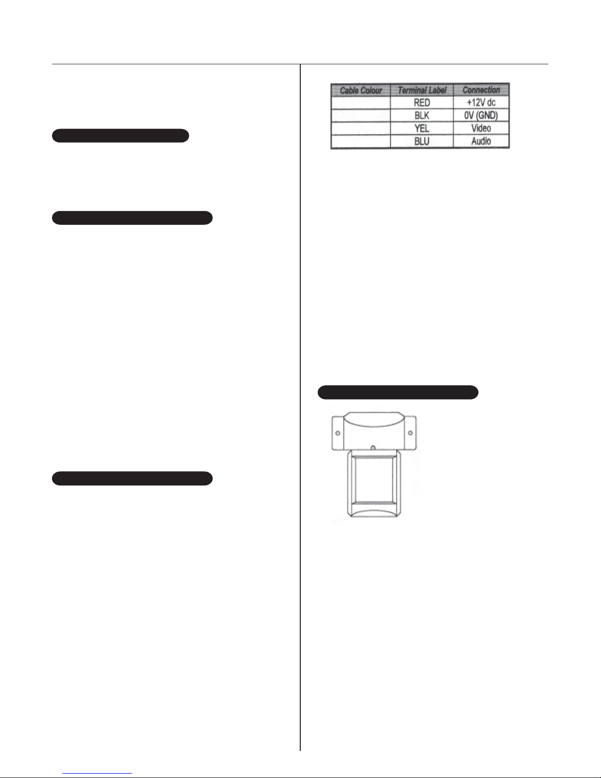
2. Connect the cables to the camera using the table below
to make a note of the colours used and the function of
each wire.
INST ALLING THE CAMERA
Installation Instructions
Note that the 0V connection should be used to
provide the ground (GND) signal for the video and
audio signal.
3. Connect the power, video and audio connectors on
the other end of the cable into the CCTV
equipment.
4. Check all connection thoroughly .
5. Switch the power on to all the equipment.
6. Select the camera input on the device that the
camera is connected to. You should now see and
hear the camera’s output.
7. You can now check the camera’s view in different
positions enabling you to choose the best position
for your property.
SITING THE CAMERA
The camera is suitable for
indoor or outdoor use.
Please bear in mind the
following points when
choosing a mounting
position.
• The camera must be positioned so that it will not
point directly into the sun (sunrise and sunset)
or any bright light, as this may cause damage to the
camera.
• The best viewing angle is achieved at greater
heights with the camera pointing down.
• Avoid viewing areas where half the area is in bright
sunlight and the offer half is dark, such as in the
shadow of a building. All types of cameras have
difficulty in ‘seeing’ with such a large lux level
variation.
• Bear in mind not to position the camera too far away
from door entrances as you may not be able to hear
any speech or sound.
• The camera will work in low light conditions, but
ensure a light is fitted near to the camera for
night-time operation.
Page 2

1. Once the camera position is chosen, switch the
power off.
2. Remove the wires from the camera.
3. Run the camera cable from the CCTV
equipment to the desired mounting position.
4. Re-connect the wires to the camera as shown
in the table on the previous page.
5. Place the cable tie provided around the outer insulation of the cable to prevent the cable from being
pulled through the grommet.
6. Screw the lid back onto the camera using the
four screws.
7. Screw the camera to the chosen surface using
the plastic wall plugs and screws provided.
8. Re-apply power and select the camera input. Any
slight adjustments to the viewing angle of the camera
can now be made by panning and tilting the camera.
Once this is complete, the camera can be locked into
position by tightening the screw above the camera
lens. Do not over-tighten as this may stop you from
loosening the screw to make any slight adjustments in
the future.
This product has a 2 Year parts and labour warranty. The
warranty does not cover any damage caused by incorrect
installation, unauthorised additions or modifications to the
product, faults resulting from other manufacturers
equipment malfunctioning, or natural disasters (including
lightning damage). in the unlikely event that you encounter
a problem with this product, it should be returned direct to
Vottek, or the Voltek distributor from where the product
was purchased. Products covered by the warranty will be
repaired free of charge. A small charge will be made for
units not within the warranty .
INST ALLING THE CAMERA
WARRANTY
SPECIFICATIONS
General
Operating voltage 12V dc
Video signal 75W EIA composite video
Operating temperature -10°C to +40°C
Weatherproofing IP54
Overall size 89W x 100H x 83D (mm)
Total package weight 0.25Kg
1861 B&W Camera
Current consumption 100mA
Camera B&W CCD
Lens 3.6mm - 90° angle
Resolution 420 horizontal TV lines
Minimum illumination 0.1 lux
1869 Colour Camera
Current consumption 150mA
Camera Colour CCD
Lens 3.6mm - 70º angle
Resolution 330 horizontal TV lines
Minimum Illumination 4 lux
Churchill Way, Lomeshaye Ind Est,Nelson, Lancashire. BB9 6RT, England
Tel (01282) 695500 Fax (01282) 695511 International (+ 44 1282)
Email: sales@voltek.co.uk Website: www.voltek.co.uk
 Loading...