


VC-4820
Programmable DC-DC Converter with Battery Charger function
USER'S MANUAL
1. INTRODUCTION
This MCU controlled Step Down DC-DC Converter has a digitally adjustable output in 0.2V increments.
This unit can also be set up and used as a Two Stage Battery Charger.
Output voltage and current are displayed in turn or selectively by the LED display.
8 fault codes can be displayed for different fault diagnosis by the LED display.
Intended Applications
* Ideal for voltage sensitive loads, devices and equipment that are distant from the DC source.
* Remote Automatic or Manual On/ Off Control of the output makes it ideal for various DC power and DC
management applications.
* Suitable for on-board charging of stand-alone 12V Battery Bank or a Battery with load.
2. FEATURES
1. Digitally adjustable output voltage in 0.2 V increments (12V-15V DC) makes this unit ideal
to operate voltage sensitive devices.
2. 2 stage Battery Charger mode with 14.3V Bulk and 13.6V Float charge.
3. 3 digit LED display for displaying Voltage, Current, Operation Mode and Protection/ Fault Diagnosis.
4. Remote Control Terminal for Manual or Automatic On/Off control of the output power.
5. Remote Voltage Sensing for optimal and accurate powering of distant load or charging of a battery.
6. Remote alarm terminal (12V, 0.25A) for powering external warning device when input is under 42V.
7. A separate always-on auxiliary output (12V, 0.5A) to power critical electronic devices such as security
device or remote On/Off manual switch.
8. Fail-save protection, with 7 self-recoverable and all with fault code on LED display.
9. Thermostatic control cooling fan.
3. CAUTION
1. When an inductive load such as motor or a solenoid is used, a diode (400V, 3Amp) must be installed
across the load as shown in (Connection Diagram 1). This will protect the converter from the high
voltage spike generated by the load when the supplied current is being switched OFF.
2. When the fuse is blown, repair the problem and then replace the fuse with the same type and rating.
3. Avoid touching the heat sink during operation as it may burn you.
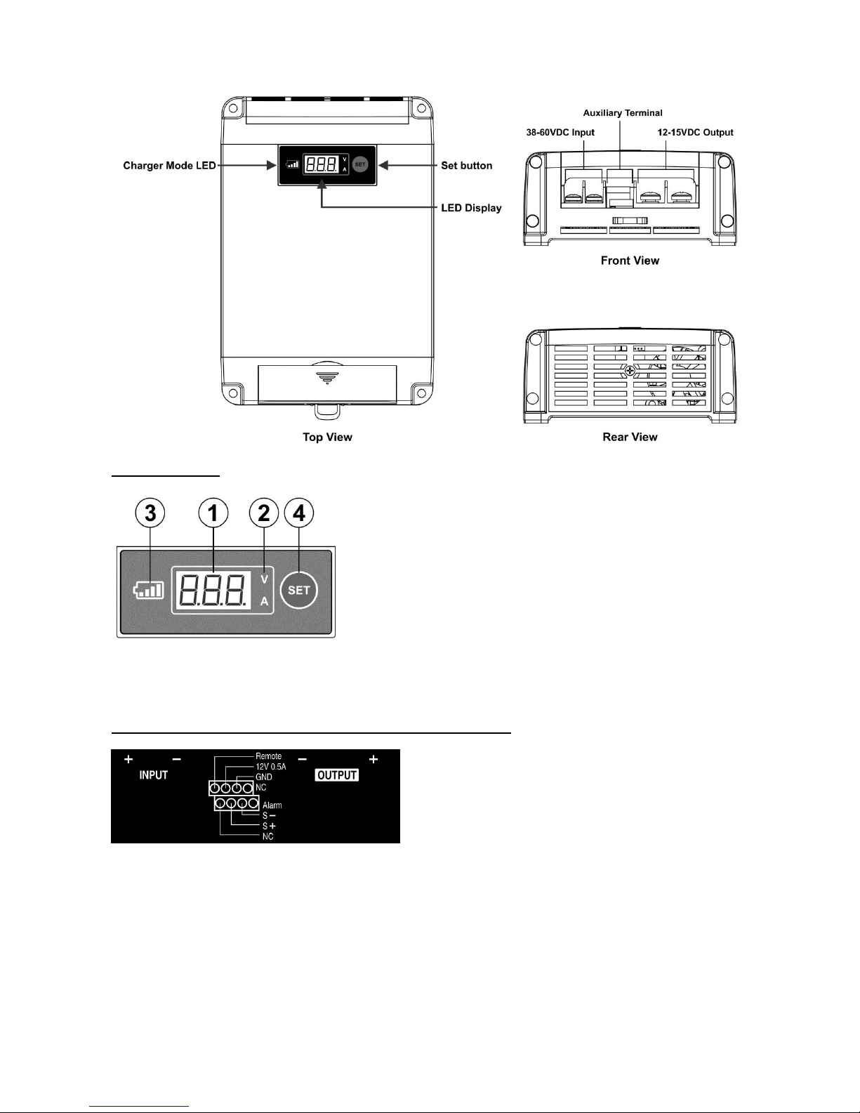
4. PANEL VIEW
1. 3 digit LED. Displays voltage, current, operation and fault code.
2. LED indicates Voltage (V) and Current (A).
3. Battery Icon is on when converter is set at the charger mode.
4. SET button.
5. INPUT, OUTPUT, CONTROL & AUXILARY TERMINALS VIEW
Remote Remote Terminal for Automatic / Manual control of Output On-Off
12V 0.5A Always On Auxiliary Output
GND Ground terminal
NC No connection, a dummy terminal
Alarm Alarm for low input voltage by DC +12V and 0.25A to power warning device (LED)
S+ S- Voltage Remote Sensing positive and negative terminals,

6. Wiring Diagram
6.1 Connection Diagram 1
Example 1
Example 2
Example 3

6.2 Connection Diagram 2
7. INITIAL SET UP AND CONNECTION
1. Leave the output terminals disconnected.
2. Connect a 48V battery to the input terminals.
DOUBLE CHECK FOR CORRECT POLARITY BEFORE CONNECTION.
3. Programming Procedure using the SET button .
4. Press and hold the SET button until shows up and display flashes.
5. Flashing digits indicate unit is in programmable mode.
Otherwise repeat step 4 to get to programmable mode again.
6. Each short press will increase the output voltage setting by 0.2V steps-> 15.0V -> CHA (Charger Mode).
And then back to 12.0V as shown in the following cycle chart.
6. Stop at the desired Output Voltage or at the if you select to set to battery charger mode.
7. After few seconds, the display will stop flashing to confirm the selected setting. The unit will then
operate in new set voltage output or as a battery charger.
8. Now you can connect the output terminals to a 12V device or to a 12V battery. Always double check for
correct polarity.
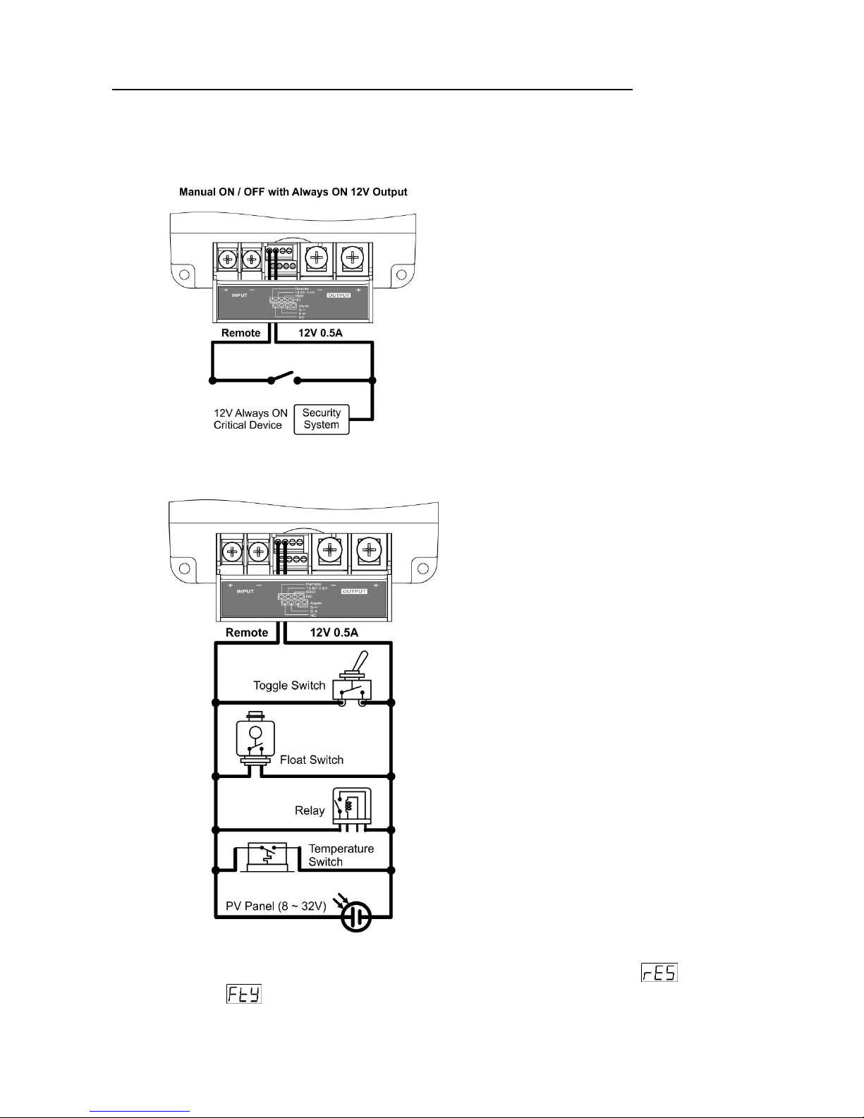
8. REMOTE TERMINAL FOR AUTOMATIC / MANUAL OUTPUT ON-OFF CONTROL
1. The DC-DC Converter can be set to control the output Manually or Automatically.
2. Application of the Remote Control Terminal:
A. The converter can be set to manual control of the output via external switch
B. The remote On/Off function can be controlled via many types of On/Off switches and with various
DC sources between 8V-32V.
3. Once the Remote Terminal has been connected to a positive 8-32V, the converter will be modified to
Remote Control Mode and will remain in this mode until it is disabled either by reset , or to
factory preset . See section 11 and 12 for more detail information.

9. GENERAL OPERATION
LED Display
During operation, the LED display will display sequentially Voltage and Amps.
A quick press of the SET button will either hold the display (at desired V, A) or return to the default scrolling
mode.
The display will switch off after 5 minutes to conserve the energy. Display can be restarted by a quick press
of the SET button.
When the output current is less than 1 Amp or output is open circuited the LED display will show
indicating Low Output Amp. This applies to both converter and charger mode.
Battery is fully charged when the output float voltage is 13.6V and the current to the battery is less than
1Amp.
Remote Voltage Sensing
Voltage converter can be finely tuned to supply your device with the required voltage even when your device
is at a distance. You can use the remote voltage sensing terminals (S-, S+) to ensure accurate voltage is
supplied to the load.
Alarm Terminal
The Alarm terminal is for input low voltage alert (F05). It provides 12V, 0.25A to power remote LED to give
out alarm before the converter falls into low voltage protection mode and shuts down. The alarm signal will
turn On when the input is below 42V and will turn Off when the input rises back above 50V.
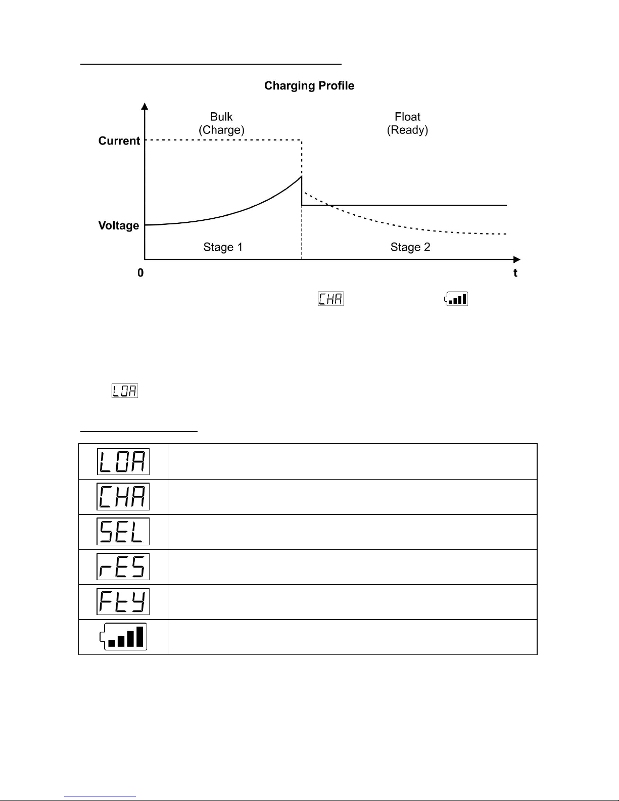
10. BATTERY CHARGER MODE - TWO STAGE CHARGER
When the unit is set in Charger Mode, LED Displays and the charger icon will be lit up to
confirm the Charger is in operation.
Bulk Charge is set at constant current of 20A and voltage at 14.3V. Float Charge voltage is set at 13.6V.
The Charger Icon flashes in Bulk Charge and becomes constant in Float Charge.
Quick press the SET button to display charging Voltage and Current.
Please note that when the battery is full and the float charge current is less than 1A, the current display
shows
11. DISPLAY INDICATION
Low Current Display when the output current is less than 1 Amp
CHARGER Mode
SELECTION (programmable) Mode. Ready for programming of output voltage &
charger mode
REMOTE CONTROL DISABLED, there is always output when input is powered up
FACTORY DEFAULT SETTINGS ENABLED (see section 12 for default settings)
Flashing = Bulk Charge, Solid = Float Charge

12. TO ACTIVATE AND DEACTIVATE REMOTE CONTROL MODE
The Remote control terminal is disabled by default at the factory and the output is always on.
To enable the Remote Control Mode, apply a positive 8 to 32VDC to Remote terminal.
After Remote Control Mode has been enabled it will stay enabled until it is disabled or reset to factory default
setting in 12.
To disable remote control mode
- Press and hold SET button until is shown.
- Release button then wait for few seconds. The remote control will be disabled and the output will stay
always ON.
13. FACTORY DEFAULT SETTINGS
1. Unit is in DC-DC Converter Mode with Output Voltage set at 13.8V
2. Remote Control is disabled and the Output is always ON.
You can reset DC-DC Converter to factory default setting by following steps:
- Press and hold SET button until is shown.
- Release button then wait for few seconds. The converter is reset back to factory default setting.
14. DISPLAY ON/OFF
The display will be switched off automatically after 5 minutes. Press the Set Button to restart the display for
another 5 minutes.
15. ALWAYS ON AUXILIARY OUTPUT
The DC-DC Converter will provide constant 12V, 0.5A to power critical devices such as security or alarm and
will supply a positive voltage source for manual remote On/Off control of the output.
Upon connection of the input to the 48V battery supply, the 12V terminal will be powered.
16. REMOTE VOLTAGE SENSING PORTS
The remote voltage sensing operates for both Converter mode and Charger mode. It compensates for
voltage drop at a distant load or auxiliary battery.
It further enhances the stability of the output voltage to the distant connected load or battery.
Connect the cable from the Positive S+ to Positive of load / battery and Negative S- to Negative of load/
battery.
17. ALARM -- The low input voltage pre-warning
The alarm signal port provides 12V 0.25A for external LED or other alarm device to give pre-warning signal
when input voltage drops below 42V before further dropping to 38V at which the output shuts down.
18. LOW CURRENT DISPLAY
The display will show when the output current is less than 1Amp.
The converter can be in converter or charger mode or when the output is open circuit.
When in Battery Charger mode, it will mean that the battery is charged.

19. Troubleshooting
If no display comes up after connection to the input, check for correct input polarity.
Disconnect all cables to the unit and check the input fuse.
The LED will display an error code when the converter is in any protection mode.
The following table denotes the 8 Error Codes.
Error Code
Description
F01
Over Temperature Protection (Self-restart)
When unit’s internal temperature becomes higher than the threshold value, unit shuts down the
output. Unit will resume normal operation automatically once the temperature becomes normal.
F02
Output Over Voltage Protection (Self-restart)
In DC-DC Converter Mode, output shuts down when the output voltage is 15% higher than the
preset voltage level. Unit will self-restart when the output voltage falls 1V below the preset
level.
In the Bulk Charge Stage of Charger Mode, the unit shuts down >16V and restarts when the
voltage <15.5V.
In Float Charge Stage it shuts down when voltage >15.1V and restarts at < 14.6V.
F03
Over Load Protection (Self-restart)
When the Output current is 2 Amp higher than 20A, the unit will shut down the output.
The unit will self-restart once the output current falls back to unit’s rated value.
F04
Fan Fault (Self-restart)
When the fan does not operate normally, the unit will shut down the output. Unit will resume
normal operation once the fan fault condition has been removed.
F05
Input Low Voltage Protection (Self-restart)
Input V < 42V
Alarm signal On
Input V > 50V
Alarm signal Off
35V < Input V < 38V for 3 min.
Output shuts down; self-restart > 50V
Input V < 35V
Output instant shut down; self-restart >50V
F06
Output Short Circuit Protection (Self-restart)
Unit shuts down output when the output is short circuited.
It will self-restart when the fault condition is removed.
F07
Output battery terminal reverse polarity protection
Fuse will be blown when the output is reverse polarity connected to the battery.
Replace the fuse with correct type and rating.
F08
Input over voltage protection (Self-restart)
Output shuts down when the input voltage is higher than 64V.
It will self-restart when the input drops below 61V.

20. SPECIFICATIONS
Models
VC-4820
Input Voltage Range
38 - 60VDC
Output Voltage Range
12 – 15VDC (0.2V increments)
Continuous Output Current
20A
No load current
< 60mA
Efficiency
≥ 90%
Protections
Over Voltage, Overload, Input Reverse Polarity, Over Temperature,
Output Reverse Polarity, Output Short Circuit, Input Under Voltage
Aux. Output (Always On)
12V / 0.5A
Two Stage Battery Charger
Bulk Charge 14.3V Max. Constant Current 20A, Float Charge 13.6V
Remote Control of Output ON/OFF
Yes Automatic or Manual Control
Remote Voltage Sense
Yes
External Alarm Output
13.5V, 0.25A
To power warning device when the input is under voltage before the
shutdown.
Indicators
3 digits LED display for V, A & Error code and Battery Charger Indicator
Cooling System
Thermostatic Control Fan
Operating Temperature
-10°C to +50°C
Approvals
EN 55014, EN60335.2.29
Accessory
Supplied four cable lug connectors and one 400V 3A diode
Dimensions (W x H x D)
130x55x190 mm
Weight
1.4kg
Recommended Battery Capacity
Range
66AH to 200AH
REV.1 2016/10/19
7673-5420-3520
 Loading...