

Voltech TS-300 Series, TS-1000 Series, TS-600 Series, TS-1500 Series, TS-2500 Series Instruction Manual
...
WARNING:
·Pure sine wave output(THD<3%)
·High efficiency up to 92%
·Optional remote purchased sepperately
·LED indicator and buzzer
·Can be used for most electronic products with AC input.
·Battery low alarm and indicator
·Compliance to CE / FCC / LVD / RoHS
INSTRUCTION MANUAL FOR PURE SINE WAVE INVERTER
Batteries may have a performance issue over time. It is recommended to perform regular checks and maintanance
(e.g. every year). If the batteries have failed or are no longer performing, the batteries should be changed by a
professional technician, otherwise, the failed batteries may cause a fire or other hazard.
The TS inverters (Or Trade Series) are pure sine wave inverters that are CPU controled. They convert DC power
into AC power. They do not produce power, but only convert.
They are durable and can run for long periods at a time, however they are not designed for continuous use.
Peak power is double the continuous power output for start up.
They are designed for most loads. However, they are not recommended for induction cookers.
Features
· Only connect batteries with the same size and type in one battery bank. Using batteries from different
manufacturers or different capacity is strictly prohibited.
· Never allow a spark or flame in the vicinity of the batteries as this may ignite explosive gases when opperating.
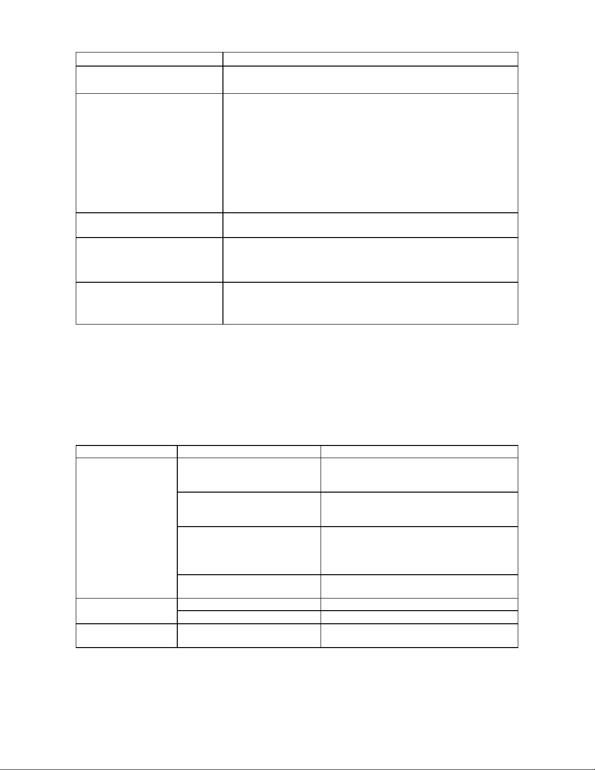
· Make sure the air flow from the fan is not obstructed at both sides (front and back) of the inverter. Allow at least
15cm of space from both sides.
· Do not place any objects ontop of the inverter
WARNING:
NOTE: This is a general manual.
Product Introduction
Safety Guidelines (Please read through this manual before installing)
· Risk of electrical shock and energy hazard. All failures should be examined by a qualified technician. Please do
not remove the case of the inverter yourself.
· Do not install the inverter in places with high moisture or near water. (warranty is void if liquid damage occurs)
· Do not install the inverter in area with high ambient temperature, in direct sun or near a flame source.

Main Specifications
Output Waveform
Model
Continuous Power
Peak Power
No Load Current Draws
Dimensions(L*W*H)cm
Weight (kgs)
Efficiency up to 92%
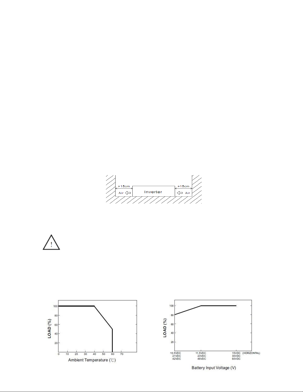
DC12V DC24V DC48V
10-15.5V 20-31V 40-61V
Low voltage protection 10±0.5V 20±1V 40±1V
Over voltage protection 15.5±0.5V 31±1V 61±1V
Output Voltage 100V/110V/115V/120V/220V/230V/240V
Frequency 50Hz/60Hz
Fuse Internal or external
USB Port 5V, 2A
Grounding Ground Chasis: Do not ground to battery negative or inverter negative.
Remote control Sold seperately. Connects with either 5m or 8m cable option.
Application
0°C--+40°C @ 100% load; ≥ +60°C @ 50% load
Operating relative humidity 20%--90% RH non-condensing
-30°C--+70°C
Auto starts when internal temp ≥ 45ºC, or load is ≥30%
Output Protection
Caravans, RVs, boats, turcks, laptops, TV sets, video games, Cdplayers, DVD
players, power tools, office equipment, major household appliances, etc. Not
recommended for induction cookers.
Input Voltage
Protection Function
D: Low Voltage Shutdown Protection:Battery Voltage too low. The inverter will auto recover after the battery
voltage is above 12.5V. The inverter will only try 10 times, if within this amount of tries the voltage does not rise
above 12.5V the unit will shut down. All figures are double for 24V models. see below table for details.
E: Output Overload Protection(OLP):When the output is overloaded to 120%, the inverter will automatically
shutdown and the buzzer alarm will sound 3 times continuously. The fault light will flash red at the same time.
The LED and buzzer will indicate the below protections (see below table for details)
A: Over Temperature Protection(OTP):When the inverter's internal temperature is higher than 65 degrees, the
"Over Temperature Protection" will be activated. The buzzer will sound 5 times continuously, and fault light will flash
red. When the internal temperature drops below 45 degrees, the inverter will automatically return to normal status.
B: AC Output Abnormal Protection:AC output too high OR too low, output shuts off. Inverter needs to be
restarted.
C: AC Output Short Circuit Protection: Short circuit on output, or the load increases suddenly, output shuts off,
inverter needs to be restarted.
Storage temperature
Cooling Fan
Environment
Operating temperature
Low voltage shutdown protection
Over input voltage protection
Over temperature protection
Over load protection
Short circuit protection
Reverse polarity protection
< 1.0A
< 1.2A
1.0 ± 0.2
1.4 ± 0.2
3.9 ± 0.2
7.0 ± 0.5
21x12x5.2
26x12x5.2
30x22x8
36x22x8
46.5x22x8
5.0 ± 0.2
600W
1200W
2000W
3000W
4000W
< 0.5A
< 0.5A
< 0.7A
< 0.7A
< 1.0A
300W
600W
1000W
1500W
2000W
TS-1000-XX
TS-1500-XX
TS-2000-XX
TS-3000-XX
5000W
6000W
2500W
3000W
TS-300-XX
TS-600-XX
TS-2500-XX
Pure Sine Wave (THD<3%)
Fault Indication
LED and Buzzer
Status Possible Cause
Fan does not spin
Installation & Wiring
Note: this is a guide only. It is the responsibility of the installer to ensure correct wiring.
Solution
Short circuit protection
Batteries are aged or broken
If the unit has been tested and found faulty, you must get a RMA number before sending the unit in.
It is highly reccomended that wire connections be as short as possible, and less than 1.5 meters if possible. Long
DC wires may have Voltage drop and reduce the overall performances of an inverter. Make sure that suitable wires
are chosen based on the rating of current. Too small of a cross-section may result in low input and high heat.
Check the DC input source. Make sure the
voltage is within required range AT
TERMINALS.
Make sure that the ventilation is not blocked or
the ambient temperature is not too high.
Minimize load or reduce heat.
Make sure the load isnt too hihgh for the unit. Or
the start up current is not too high. (for inductive
or capacitive loads) Startup can be as high as 710 times cont rating (will overload)
Make sure the output is not overloaded or shout
circuited.
Get batteries tested. Replace batteries.
Connection. Obstruction. Faulty
Check that the load is not too large for battery
Check the leads for fan on PC board. Remove
any obstruction.
Condition
Buzzer sounds 3 times (LED
flashes red 3 times)
The inverter should be serviced by a professional technician. Any incorrect usage or modification may damage the
unit or result in shock hazard or damage to the unit. If you cant clear the fault condition, contact your place of
Batteries are not lasting
Battery capacity is too small
Overload protection
Abnormal input
Over temperature protection
No AC output voltage
Buzzer sounds 4 times (LED
flashes red 4 times)
Buzzer sounds 5 times (LED
flashes red 5 times)
You must contact Electro Parts for a Return Manufacturer Authority (RMA) number
Fault Conditions
Buzzer sounds once and LED
flashes green once
Buzzer sounds 3 times (LED
flashes red 3 times)
This indicates normal operation. This occurs when the unit starts up.
Low voltage protection: These units have three stages of UVP;
1) WARNING: Single slow warning beep & LED flash when Input is
below 11.2V.
2) AC SHUTOFF: Below 10.5V the Output shuts off & 3 beeps with 3 x
LED flashes.
3) INV SHUTDOWN: It will then repeat this cycle 10 times ( 3 x beeps / 3
Flashes x 10), unless the input Voltage increases to above 12.6V within
that time, It will completely shut down so as to not draw any power from
the battery (The unit will need to be switched back on manually). (all
figures are double for 24V units)
Over load protection: The load is 120% higher than rated power.
Reduce load and restart. THIS ALSO INCLUDES START UP POWER.
Over voltage protection: The battery voltage is too high. Make sure
input voltage is lower than 15.5V for 12V models and 31V for 24V
models.
Over temperature protection: The internal temperature is too high.
Reduce temp and make sure there are no vents being obstructed. Make
sure there is enough ventilation.
NOTE: diagnosing the fault without the unit being tested is not practical. If you cannot get the unit tested, you can
return/ freight the unit back to Electro Parts Aust Pty Ltd
Suggested Battery Bank Capacity
Note: this is a guide only. It is the responsibility of the installer to ensure the correct battery bank is installed.
·Simple calculation of battery discharge time:Battery capacity / discharge current = discharge time
eg:12V/220V/50Hz/300W full load of inverter100% Efficiency 89%
Discharge time is 1 hour. What is the optional battery capacity?
·Select the battery size according to the following formula:
⑴ 300W÷89%=337W Output power/efficiency = input power
⑵ 337W÷10.5V=32A Input power / battery voltage (lowest operating Voltage) = Input Current
⑶ 32A×1hour=32AH Input current × discharge time = battery capacity
⑷ a 40Ah battery can be discharged in 85 minutes.
Note: (Actual discharge time error may exist according to the lifespan and mantainenece of the battery.)
Ventilation and Positioning
(Note: There should be no obstruction within 15cm of the ventilating holes.)
Mounting Suggestion:
Output and Load
CAUTION
Input Derating Curve
The unit should be mounted on a flat surface or holding rack with suitable strenth. In order to ensure the lifespan of
the unit, please refrain from operating in environment of high dust, high temperature or high moisture. This is a
power supply with built-in DC fan. Please make sure that ventilation is not blocked.
install in a horizontal position using the mounting points provided. Install in a dust & moisture free area.
The inverter can power most loads that need an AC source which need to be powered continuously. This applies to
light loads such as phone chargers and light loads. It is not reccomended to run heavy loads continuously.
(1) Since inductive loads or motor based appliances need a large start up current (6~10 times the rated current), the
inverter may not start up successfully with these kinds of loads. Induction cookers cannont be used on these
inverters for this reason.
(2) When using capacitive or switched loads(such as a power supply), to ensure proper operation, only turn on the
load or increase the load after the unit has been turned on. Do not start the inverter with the load on.
A battery bank that is of larger capacity than needed should be installed. (to meet the discharge time and load
requirements) The time that a load can run for is NOT determined by the inverter, rather than by battery capacity.

Installation Diagram
Inverter Components
Please note the following labels are the same for all units.
FRONT
REAR
a. DC battery terminals: connect the inverter to batteries or other power sources.
both terminals should be kept insulated to protect from accidental short circuits.
b. Cooling fan: temperature and load controlled.
Warranty
No warranty is given for any liquid damage or vermin/insect or any damage by animals, or excesive abuse to the
unit that is caused by vibration or any other operation that is not fit for the unit.
12 Month back to base warranty. See www.electroparts.com.au for general warranty and return statement.
Rear panel of 300W-600W
Front panel of 1000W-3000W
Rear panel of 1000W-3000W
Front panel of 300W-600W
b. AC OUT: Australian socket
c. Ventilation outlet: to cool the inverter. Do not obstruct
d. FAULT/POWER: LED indicator. Green: normal operation. Red: fault and warnings (see table)
a. ON/OFF switch: This switch controls ON/OFF operation of the unit.
 Loading...