

Page 1
QUICK START GUIDE - USING MULTIPLE DC1000S WITH A LCR METER PAGE 1 OF 3 104-174/1
The high output impedance of the DC1000 allows it to be used with almost any manufacturer’s LCR meter.
The unique topology also allows you to parallel up to 20 units so that up to 500A can be generated.
The following document explains how to setup your environment to use multiple DC1000s with an LCR meter.
In the following example we will connect 3 DC1000As together to provide 0-75Amps whilst measuring using an LCR Meter.
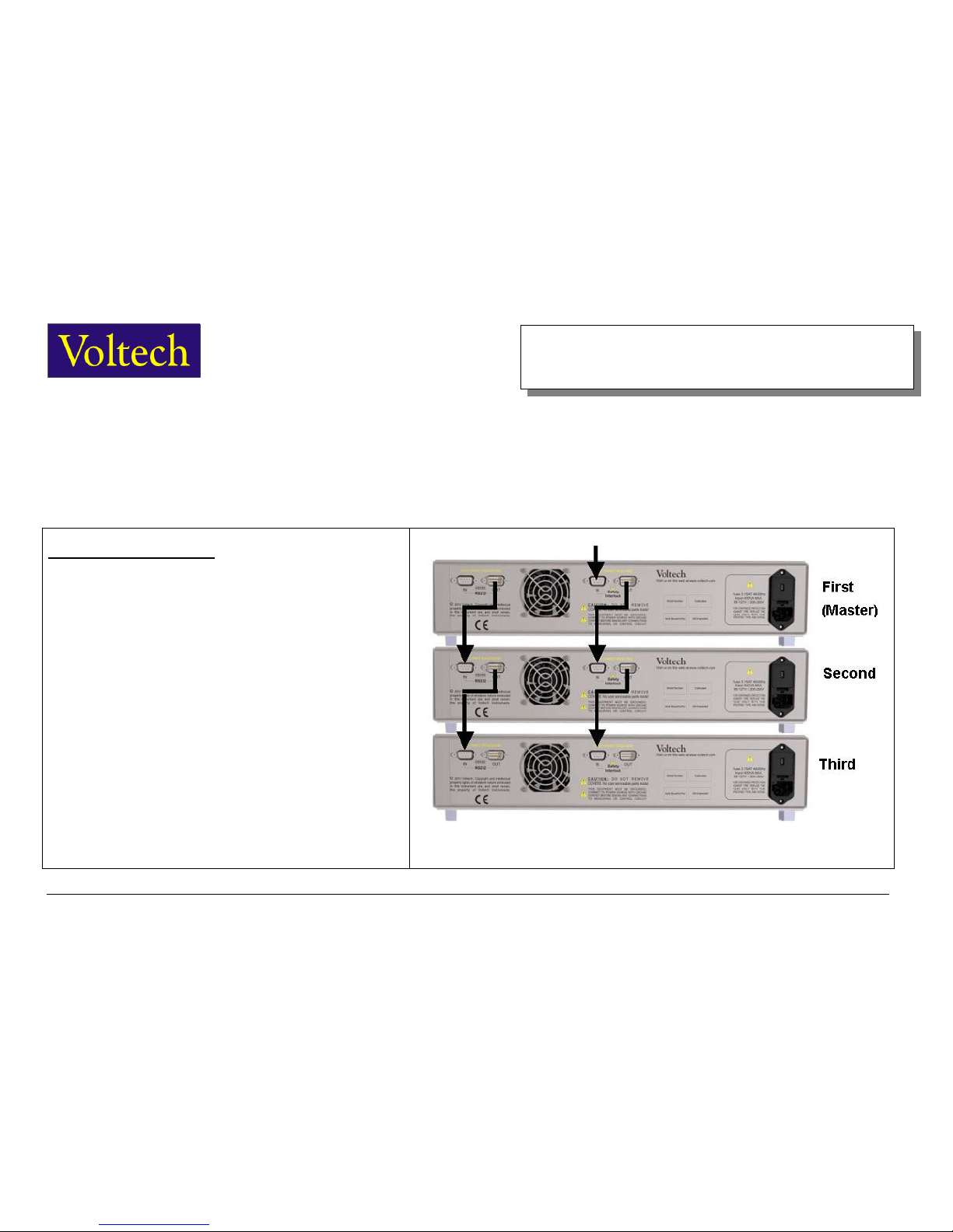
A) Connect RS232 + Interlocks.
RS232.
Use the 77-046 straight through 9w-9w M-F leads provided with the
unit.
Connect RS232 OUT from the first unit to the RS232 IN on the second
unit.
Connect RS232 OUT from the second unit to the RS232 IN on the
third unit.
The first unit will automatically become the “
Master
” unit and will
control the other units in the chain.
Safety Interlocks.
Insert your interlock system or interlock override plug into the
Interlock
IN
on the first unit.
Connect
Interlock OUT
on the first unit to
Interlock IN
on the second
unit.
Connect
Interlock OUT
on the second unit to
Interlock IN
on the third
unit.
www.voltech.com
Quick Start Guide
Using Multiple DC1000s with a LCR Meter
Page 2
QUICK START GUIDE - USING MULTIPLE DC1000S WITH A LCR METER PAGE 2 OF 3 104-174/1
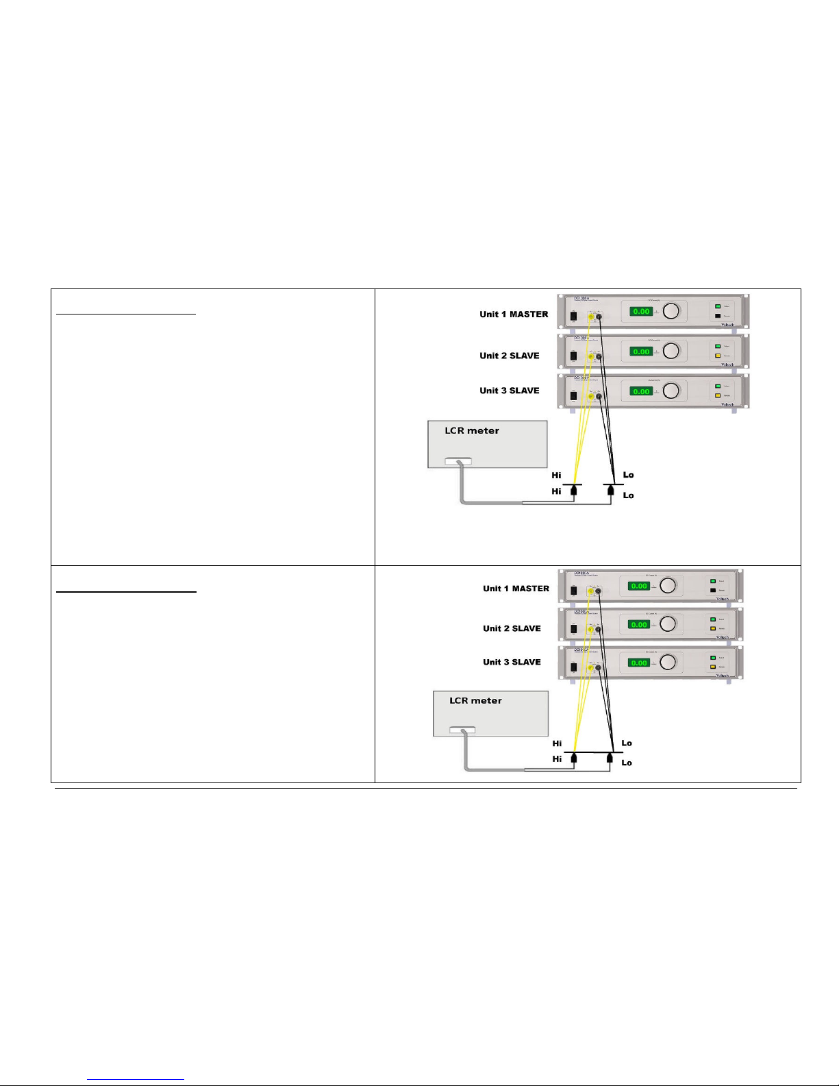
B Open circuit Compensation
1 Remove any
UUT
(unit under test).
2 Connect the DC1000 outputs in
parallel
using the test leads
provided.
Make sure the leads common together at the point of contact with the
UUT. Try to keep all test leads in the same position as when the UUT
is present.
3 Turn the DC1000s and LCR meter
ON
and allow to warm up for 30
minutes.
4 Set DC1000 on the
MASTER unit
to
0.00 AMPS
, using rotary knob
if needed.
5 On the
MASTER
unit, set DC1000 output to
ON,
by pressing “output”
button. All 3 green
OUTPUT LEDs
will light.
The 2 slave units orange
REMOTE LEDs
will also light showing they
are being controlled by the Master unit.
6 Perform
Open Circuit Compensation
on your LCR meter
(sometimes called “
Open Correction
”).
7 Remember to compensate at
all frequencies
at which you want to
measure.
8. Press the Master
OUTPUT
button to turn all the DC1000s OFF.
C Short circuit Compensation
1 Fit a short between all leads. A Bus Bar or thick copper wire is ideal
for this, as it will give good contact to all 4 clips. Try to keep all test
leads in the
same position
as when the UUT is present.
2 Set DC1000 to
0.00 AMPS
, using rotary knob if needed.
3 On the MASTER unit, set DC1000 output to ON, by pressing “output”
button. All 3 green
OUTPUT LEDs
will light.
The 2 slave units orange REMOTE LEDs will also light showing they
are being controlled by the Master unit.
4 Perform Open Circuit Compensation on your LCR meter
(sometimes called
“Short Correction
”).
5 Remember to compensate at all frequencies at which you want to
measure.
6 Press the Master OUTPUT button to turn all the DC1000s OFF.
Page 3
QUICK START GUIDE - USING MULTIPLE DC1000S WITH A LCR METER PAGE 3 OF 3 104-174/1
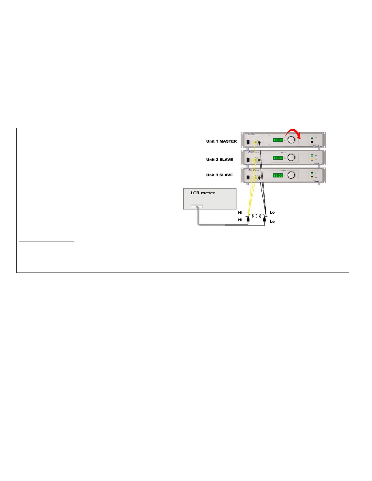
D Running 3 units in parallel
Once you have compensated the LCR for the leads and DC1000s you
can now make measurements under load.
1 Turn the DC1000 output
OFF.
2 Add your UUT back into the circuit, attempting to keep the test leads
in the
same position
as when compensating.
3 Select the DC Bias Current you require using the rotary knob on the
MASTER
unit. The Slave units will adjust automatically. In the example
shown each unit is providing
15.00 AMPS
to give a total DC bias
current of
45.00 AMPS.
4 Enable the DC Bias Current by pressing
OUTPUT
on the
MASTER
unit
5 Perform measurements on the
LCR.
6 Adjustments can be made to the DC BIAS level while the output is
enabled (and the LCT is measuring) using the
rotary knob
.
E Best Practice / Warnings
1
DO NOT
disconnect the UUT or LCR whilst the DC1000 is operating.
2 Always remove the DC BIAS current by
disabling the OUTPUT
button before disconnecting
either the UUT or the LCR meter.
3 Always try to keep all leads in the
same position
to improve the accuracy of the
compensation, and hence the accuracy of your measurements.
 Loading...