


V
V
www.voltech.com
AT
ATi
ATAT
i
ii
USER MANUAL
oltech Instruments Inc.
11637 Kelly Road
Suite 306
Fort Myers FL 33908, U.S.A.
Tel: 239 437 0494
Fax: 239 437 3841
sales@voltech.com
VOLTECH ATI USER MANUAL PAGE I
oltech Instruments Ltd.
Harwell International Business Centre
Didcot, Oxon OX11 ORA, U.K.
Tel: +44 (0) 1235 834555
Fax: +44 (0) 1235 835016
sales@voltech.co.uk
148 6
th
Street

Voltech Instruments is committed to a policy of continuous
product development. Hence, product specification and the
information given in this manual are subject to change
without notice.
No part of this publication may be reproduced, stored in a
retrieval system, or transmitted in any form, or by any
means, electronic, mechanical photocopying, recording or
otherwise, without prior written permission of Voltech
Instruments.
Voltech Instruments 2002-2005. All rights reserved.
The Voltech ATi is protected by the following patents:
USA: US 5500598
UK: 2261957B
Europe: 0621953B
Microsoft, Windows and the Windows logo are either registered trademarks
or trademarks of Microsoft Corporation in the United States and/or other
countries.
Voltech Part Number: 98-067, Issue 8, October 2005.
PAGE II VOLTECH ATI USER MANUAL

DANGER OF ELECTRIC SHOCK
!
!
!
!
Only qualified personnel should install this equipment, after reading
and understanding this user manual. If in doubt, consult your
supplier.
RISQUE D'ELECTROCUTION
L'installation de cet équipement ne doit être confiée qu'à un
personnel qualifié ayant lu et compris le présent manuel
d'utilisation. Dans le doute, s'adresser au fournisseur.
GEFAHR VON ELEKTRISCHEM SCHOCK
!
!
!
!
VOLTECH ATI USER MANUAL PAGE III
Nur entsprechend ausgebildetes Personal ist berechtigt, diese
Ausrüstung nach dem Lesen und Verständnis dieses
Anwendungshandbuches zu installieren. Falls Sie Zweifel haben
sollten, wenden Sie sich bitte an Ihren Lieferanten.
RISCHIO DI SCARICHE ELETTRICHE
Solo personale qualificato può installare questo strumento, dopo la
lettura e la comprensione di questo manuale. Se esistono dubbi
consultate il vostro rivenditore.

Contents
1 INTRODUCTION ............................................................................................1-1
1.1 How to Use this Manual.................................................................................. 1-5
1.2 General Safety Instructions............................................................................. 1-6
1.3 ATi and AT3600.............................................................................................. 1-7
1.4 Tests Supplied................................................................................................1-8
1.5 ATi Features Summary................................................................................. 1-11
1.6 Typical Production Installation.......................................................................1-12
1.7 Using the ATi for Design and Evaluation.......................................................1-14
1.8 Overview....................................................................................................... 1-15
1.9 How Does the ATi Tester Run a Test?..........................................................1-26
2 Getting Started......................................................................................... 2-1
2.1 Introduction.....................................................................................................2-5
2.2 Installation..................................................................................................... 2-10
2.3 Quick Start Tutorial.......................................................................................2-19
2.4 Self-Test........................................................................................................ 2-49
2.5 Production Mode........................................................................................... 2-52
2.6 Stop on Fail................................................................................................... 2-69
2.7 Trim............................................................................................................... 2-71
2.8 Fixture Compensation................................................................................... 2-73
2.9 Set-up Mode ................................................................................................. 2-77
3 PROGRAM EDITOR.......................................................................................3-1
3.1 Creating a Program......................................................................................... 3-5
3.2 Creating the Transformer Schematic .............................................................. 3-6
3.3 Creating the Test Program............................................................................ 3-13
3.4 Using the Measure Button.............................................................................3-31
3.5 Error Codes................................................................................................... 3-42
PAGE IV VOLTECH ATI USER MANUAL

3.6 Fixture Compensation (see also section 2.8).........................................3-46
3.7 Programming Hints and Tips.........................................................................3-48
4 AT SERIES SERVER.....................................................................................4-1
4.1 Introduction.....................................................................................................4-5
4.2 Test Program Handling...................................................................................4-6
4.3 Test Results Handling...................................................................................4-11
4.4 License Registration......................................................................................4-50
5 FIXTURES ....................................................................................................5-1
5.1 Introduction.....................................................................................................5-5
5.2 Description......................................................................................................5-6
5.3 Fixture System Specification......................................................................... 5-12
5.4 Fixture Parts Available from Voltech.............................................................5-13
5.5 Kelvin Connections........................................................................................5-18
6 FRONT-PANEL MODES .................................................................................6-1
6.1 LCR Mode Basic Functions.............................................................................6-5
6.2 Tests Available in the LCR Modes................................................................6-17
6.3 LCR Menus...................................................................................................6-19
6.4 Compensation...............................................................................................6-29
6.5 LCR Mode Error Messages...........................................................................6-35
6.6 Program Mode ..............................................................................................6-39
7 TESTS AND TEST CONDITIONS ......................................................................7-1
7.1 Introduction.....................................................................................................7-4
7.2 Series and Parallel Circuits.........................................................................7-123
7.3 Capacitor Measurements............................................................................7-125
8 SPECIFICATIONS ..........................................................................................8-1
8.1 Specifications Summary – Available Tests......................................................8-5
8.2 Accuracy Specifications – Available Tests...................................................... 8-8
8.3 Interface Details............................................................................................8-25
8.4 EMC Compliance..........................................................................................8-35
9 WARR ANTY AND SERVICE.............................................................................9-1
VOLTECH ATI USER MANUAL PAGE V

9.1 Warranty ......................................................................................................... 9-5
9.2 Limitation of Warranty..................................................................................... 9-5
9.3 Service and Calibration................................................................................... 9-6
9.4 Obtaining Service and Applications Support................................................... 9-6
9.5 Firmware Upgrades.........................................................................................9-7
10 INDEX.................................................................................................... 10-1
PAGE VI VOLTECH ATI USER MANUAL

1 INTRODUCTION
Thank you for choosing to use this Voltech product. If you experience
any difficulty during installation or use of the ATi or are unsure of any of
its features or abilities, please do not hesitate to contact either your local
supplier or a Voltech main service centre as listed inside the front cover.
VOLTECH ATI USER MANUAL PAGE 1-1

INTRODUCTION
PAGE 1-2 VOLTECH ATI USER MANUAL

INTRODUCTION
Contents - Introduction
1.1. H
OW TO USE THIS MANUAL ......................................................................1-5
1.2. G
ENERAL SAFETY INSTRUCTIONS.............................................................1-6
1.3. AT
1.4. T
I AND AT3600.....................................................................................1-7
ESTS SUPPLIED .....................................................................................1-8
1.4.1. Standard Program Tests.......................................................................... 1-8
1.4.2. Optional Program Tests...........................................................................1-8
1.4.3. ATi LCR Mode Functions.........................................................................1-9
1.5. ATI FEATURES SUMMARY ......................................................................1-11
1.6. TYPICAL PRODUCTION INSTALLATION.....................................................1-12
1.7. USING THE ATI FOR DESIGN AND EVALUATION........................................1-14
1.8. OVERVIEW.............................................................................................1-15
1.8.1. Creating Programs - The Editor.............................................................1-16
1.8.2. Storing Programs and Results - The Server..........................................1-17
1.8.3. Transferring Programs between Editor and Server................................1-18
1.8.4. Executing Programs..............................................................................1-20
1.8.5. Test Fixtures..........................................................................................1-23
1.8.6. Operating the AT Series Testers in Production Test..............................1-24
1.9. HOW DOES THE ATI TESTER RUN A TEST?.............................................1-26
VOLTECH ATI USER MANUAL PAGE 1-3

INTRODUCTION
PAGE 1-4 VOLTECH ATI USER MANUAL
INTRODUCTION
1.1 HOW TO USE THIS MA NUAL
Welcome to the Voltech ATi. Please study this introductory chapter of the
manual carefully. It will help you to set-up your tester quickly and safely.
The following symbol conventions are used throughout:
Important safety information. To ensure operator safety, all safety
information must be read and understood.
!
i
Important information that explains a general principle or refers to
other sections of the manual.
The contents of this manual are believed to be accurate at the time of printing.
Voltech reserves the right, however, to change the operation or specification of
the ATi without notice. No liability is accepted for the inappropriate, negligent,
or incorrect set-up of the ATi by the user, by either manual or automated
means.
VOLTECH ATI USER MANUAL PAGE 1-5

INTRODUCTION
1.2 GENERAL SAFETY INSTRUCTIONS
WARNING: The ATi must be connected to a safety
ground (earth). Only insert the power lead into a
!
!
socket with a protective ground contact.
Ensure that the power lead is in good condition and
free from damage before use.
Replace the fuse only with the same type and rating as indicated
on the rear of the ATi.
Refer servicing only to qualified personnel who understand the
danger of shock hazards.
WARNING: The ATi wound component tester can generate
voltages of up to 500V during insulation resistance testing.
Although the available energy of the source has been
limited in accordance with EN61010-1 and can be
considered ‘safe’, care should be taken to avoid accidental
or unexpected electrical shocks.
• Ensure operators are aware of the potential shock hazard.
• Ensure operators are trained to avoid making contact with
the part being tested or any exposed parts of the fixture
during an IR test.
• Construct safe fixtures using the guidelines given in the
fixturing section of this manual.
• Beware of testing parts with high turns ratios such that a
small applied test signal can generate an unsafe high
voltage.
• Beware of energy stored with the capacitance or inductance
of the part being tested when handling the part after test.
PAGE 1-6 VOLTECH ATI USER MANUAL

INTRODUCTION
A
x
1.3 ATI AND AT3600
The ATi is one of a family of automatic testers from Voltech that share the
same fixture construction and PC Editor and Server software. ATi’s and
AT3600’s can share the same Server application, simultaneously recalling test
programs and recording test results.
AT
AT3600 ATi
ATAT
iii
Features:
20 way switching matri
PC test editor and results server ! !
Test fixture system ! !
Small signal tests ( e.g. inductance, capacitance, turns ! !
Telecom tests (e.g. return loss, longitudinal balance) ! !
Insulation resistance 500V 7000V
Hi-pot AC 5500V
Hi-pot DC 7000V
Surge testing 5000V
Magnetizing current and open circuit voltage 270V
Watts/Stress Watts !
Leakage current !
VOLTECH ATI USER MANUAL PAGE 1-7
Ti AT360
! !

INTRODUCTION
1.4 TESTS SUPPLIED
At the time of printing, the following tests are available for the ATi:
1.4.1 Standard Program Tests
CTY Continuity
R DC resistance
RLS AC resistance – series circuit
RLP AC resistance – parallel circuit
LS Inductance – series circuit
LP Inductance – parallel circuit
LSB Inductance – series circuit with bias
LPB Inductance – parallel circuit with bias
C Interwinding capacitance
QL Quality factor
D Dissipation factor (tanδ)
Z Magnitude of complex impedance
ZB Complex impedance with bias
ANGL Angle of complex impedance
TR Turns ratio and phase (+ or -) by voltage
IR Insulation resistance
1.4.2 Optional Program Tests
LL Leakage inductance
LLO Leakage inductance with user offset
R2 DC resistance match
L2 Inductance match
C2 Capacitance match
TRL Turns ratio by inductance
PHAS Interwinding phase
GBAL General longitudinal balance
LBAL Longitudinal balance
PAGE 1-8 VOLTECH ATI USER MANUAL

INTRODUCTION
Optional program tests continued…
ILOS Insertion loss
RLOS Return loss
LVOC Low voltage open circuit
RESP Frequency response
TRIM Trim adjustable part
OUT User port relay control
LSBX Inductance – series circuit with external bias
LPBX Inductance – parallel circuit with external bias
1.4.3 ATi LCR Mode Functions
Measurement Symbol Units Display
DC resistance Rdc Ohms Ω
DC resistance using high voltage source IR Ohms Ω
AC resistance – series circuit R Ohms Ω
AC resistance – parallel circuit R Ohms Ω
Inductance – series circuit L Henries H
Units
Inductance – parallel circuit L Henries H
Capacitance – series circuit CS Farads F
Capacitance – parallel circuit CP Farads F
Quality Factor Q
Dissipation Factor or tanδ D
AC impedance – magnitude of complex impedance Z Ohms Ω
Phase angle of impedance θ Degrees °
AC reactance – imaginary part of impedance X Ohms Ω
Turns ratio by voltage TR
Turns ratio by inductance TRL
Leakage inductance LL Henries H
Interwinding capacitance C Farads F
VOLTECH ATI USER MANUAL PAGE 1-9

INTRODUCTION
To determine which options were installed on your tester during
i
manufacture, check the list attached to the calibration certificate
shipped with your ATi.
PAGE 1-10 VOLTECH ATI USER MANUAL

INTRODUCTION
1.5 ATI FEATURES SUMMARY
The ATi tester is a fast, accurate and versatile automatic LCR meter.
FAST – Typically more than 10 DIFFERENT tests per second.
• 20 way switch matrix.
• Automatically switches from making measurements on one
winding of a transformer to another winding.
• Measures across different windings.
• No need to manually change connections.
• Fast execution of a sequence of different tests on multiple windings
of a transformer.
ACCURATE – 0.05% basic
VERSATILE
• Inductance from 1nH to 1MH
• Any frequency from 20Hz to 3MHz
• Any voltage from 1mV to 5V
• AC constant current source 20µµµµA to 100mA
• DC bias up to 1A
• Easy to use.
• High-speed production tester.
• Laboratory grade LCR meter.
• Upgrades and new tests installed from disk.
VOLTECH ATI USER MANUAL PAGE 1-11

INTRODUCTION
F
o
The ATi is very easy to use. However, it is a complex instrument, which can be
installed and operated in many ways.
In order to maximize the benefits that the ATi can bring to your test
environment, please study the following section carefully.
1.6 TYPICAL PRODUCTION INSTALLATION
Editor PC - used only when creating
or editing test programs.
Untested
transformers
Server PC - for handling detailed
results and large numbers of test
programs.
transformers
Tested
Pass Fail
Manual or robotic operation
• Barcode input
• Run-pad or footswitch to initiate operation
• Simple PASS/FAIL operation by an unskilled operator
Results
• Direct printing from the ATi printer port
• Results archiving to disk using the Server application
• Results for analysis can be easily exported to other Windows applications
PAGE 1-12 VOLTECH ATI USER MANUAL

INTRODUCTION
Test Program Creation
• Simple, easy to use, Windows based Editor for creating test programs.
(Chapter 3).
• Requires no software programming skills or expertise.
• Test conditions may be entered manually, or chosen automatically by
measuring a sample transformer.
Program Archive ~ Management
• Windows based Server software for easy management of all test programs.
(See chapter 4.)
• Optionally, programs may be resident in the tester for stand-alone operation.
VOLTECH ATI USER MANUAL PAGE 1-13

INTRODUCTION
1.7 USING THE ATI FOR DESIGN AND EVALUATION
• Tests: L, C, Z, D, Q, Rac, X, Z, θ, Rdc, Insulation Resistance, Turns Ratio,
Leakage Inductance. Bias current up to 1A.
• Fully programmable (5V, 3MHz) or AUTOMATIC test conditions.
• 0.05% basic accuracy.
• 4-terminal (Kelvin) connections using high quality leads supplied.
• Easy to use.
• Compensation for stray resistance, inductance and capacitance.
PAGE 1-14 VOLTECH ATI USER MANUAL

INTRODUCTION
1.8 OVERVIEW
This section gives a more detailed overview of your ATi and how to use it. It is
recommended that you read this section before attempting to use your tester.
Topics covered in this overview:
• The features and functionality of the ATi in a production environment.
• What appears in a test program.
• How programs are created, archived and then used in actual test.
• Test fixtures.
• Typical manual and robotic test situations.
• Internal functionality — How the tester executes each test.
Note:
This overview is intended as an introduction to each of the above topics, so
that you may quickly understand what may be possible. If further details are
required on any topic, they can be found in later chapters of this manual.
VOLTECH ATI USER MANUAL PAGE 1-15

INTRODUCTION
1.8.1 Creating Programs - The Editor
The test program is, simply, the list of tests that you wish to apply to your
transformer.
Individual transformers will each have their own program, but as an example, a
typical program for a three winding switch-mode power supply transformer
could be as follows:
Program:
Resistance
Resistance
Resistance
Inductance
Turns Ra tio
Turns Ra tio
Insulation Resistance
W1
W2
W3
W1
W1 to W2
W2 to W3
W1 to W2 + W3
W1
Part Number: SMPSE42-A
W2
W3
The Test Program Editor, supplied with your tester, allows you to create such a
program, without software programming skills. Each test required for the
program is selected from a list of ‘available tests’ by clicking with the mouse.
The test details (such as the transformer terminals, test conditions, and pass /
fail limits) are then entered into a form fill dialogue box.
PAGE 1-16 VOLTECH ATI USER MANUAL

INTRODUCTION
Normally, the Editor is used with the auxiliary port of the tester connected to a
spare COM-port on the PC:
PC running the
Editor software
Auxiliary port
Pull-down menus in the Editor allow you to download the program to the tester,
so that it may be run for the purposes of evaluation and modification.
1.8.2 Storing Programs and Results - The Server
The Editor software previously described allows you to create and evaluate
each individual test program. It is not intended to manage the large numbers
of test programs that may be required on a daily basis once they are in
‘production’ use. This is the function of a second PC program supplied with
your ATi called the Server.
Usually, the Server would be installed on a PC with access to a large disk that
could be attached to the PC itself, or connected via a network. The Server
(and disk) would then be used for any of the following purposes:
• To provide the master archive for test programs
• To archive test results.
• To interface to an SPC package.
• To remotely control the tester.
The tester has a separate 'server' port on its rear panel for connecting to
the PC.
VOLTECH ATI USER MANUAL PAGE 1-17

INTRODUCTION
1.8.3 Transferring Programs between Editor and Server
Within your test environment there are several possible ways in which the
Server and Editor may be installed and used, depending on how many
separate PC’s are available.
Programs
Auxiliary port
The standard installation uses separate PC’s for the Editor and Server:
Transferring a new test program from the Editor to the Server archive can be
done in any of three ways:
• Via the tester
• Directly from PC to PC via a floppy disk
• Via a network connection between the PC’s using ‘Save As’ in the editor to
transfer the program to the directory used by the Server for programs.
Server port
PAGE 1-18 VOLTECH ATI USER MANUAL

INTRODUCTION
With both Server and Editor installed on the same PC, transferring a new test
program from the Editor to the Server archive can be done in either of two
ways:
• Via the tester (if the auxiliary port connection is made).
• Directly from the Editor using ‘save as’ to the directory used by the Server
for programs.
Auxiliary port
(connected using
the Editor)
Server port
VOLTECH ATI USER MANUAL PAGE 1-19

INTRODUCTION
1.8.4 Executing Programs
Large Production Facility
The standard installation in a large production facility could use several testers,
together with a Server PC for test program and results archive:
Programs/
Results
Programs/
Results
Programs/
Results
Server
Advantages
• Convenient storage and management of large numbers of test programs
(e.g. >1000).
• Easy storage and management of test results.
• Importing results into other Windows applications for analysis.
• The Server PC can be located away from the test area, for example in a
supervisor’s office, allowing results analysis to be performed where it is
required.
• Up to eight AT series testers may be connected to each Server PC.
PAGE 1-20 VOLTECH ATI USER MANUAL

INTRODUCTION
Limitations
• Requires the Server PC to be permanently connected. This is to allow the
tester uninterrupted access to the Server, for the purposes of accessing
programs and storing results.
• Usually requires an additional PC (which could be a portable) to be attached
locally to (the auxiliary port of) one of the testers when a new program needs
to be developed and evaluated.
VOLTECH ATI USER MANUAL PAGE 1-21

INTRODUCTION
Small Production Facility
At the other extreme and possibly more suitable for a small production facility
with a single AT series tester and limited or temporary access to a PC:
1. Connect the AT to the PC (running both Editor and Server software)
as shown above when developing the test programs.
2. Download a group of programs from the Server to the AT, where they
will be held in the internal non-volatile memory.
3. Remove the PC, and run all the production test programs from the AT
internal memory.
Advantages
• Requires only occasional use of a PC (which could be a portable) to develop
test programs and load them into the AT.
• Test programs can be executed by the AT without the PC attached, which
may be of advantage if the working space is limited.
Limitations
• Suitable for small numbers of test programs (e.g. <50).
• Test results cannot be archived to disk, or analysed by other Windows based
applications.
PAGE 1-22 VOLTECH ATI USER MANUAL

INTRODUCTION
1.8.5 Test Fixtures
When running the test program in production, how do you connect your
transformer with its own arrangement of terminals to the test nodes of the AT
Series Tester?
The AT Series of transformer testers has been designed with its own test
fixture system to answer just this question:
• Fixtures are constructed on a standard ‘fixture board’ which fits into the top
surface of the tester.
• The fixture system uses Kelvin connections to give the best possible
measurements when testing wound components.
• The fixture system will
accommodate different types of
connectors suitable for both PCB
mounting and flying lead
transformers.
• A single test fixture can be used
for all transformers wound on the
same bobbin.
Please see the fixtures section (chapter 5) of this manual for more information.
VOLTECH ATI USER MANUAL PAGE 1-23
INTRODUCTION
1.8.6 Operating the AT Series Testers in Production Test
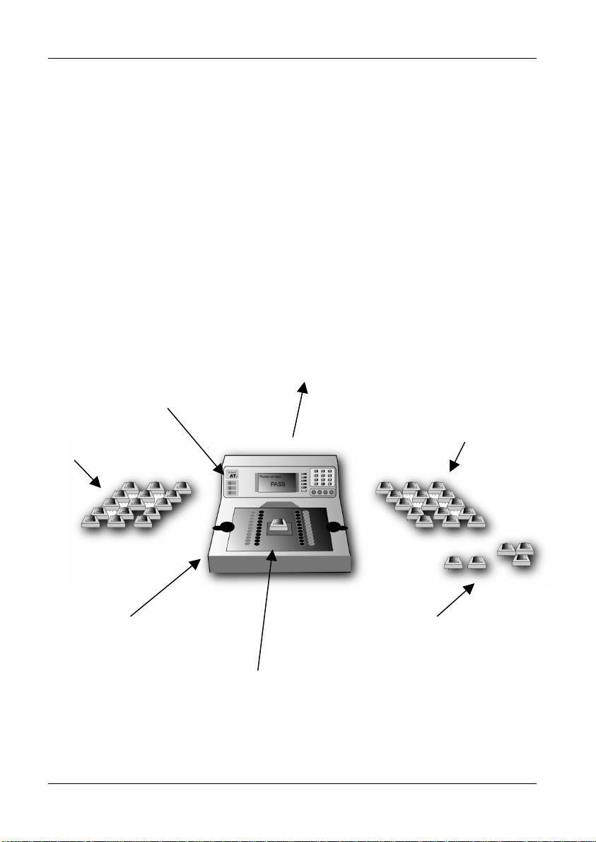
The ATi is suitable for use in both manual and robotic production situations.
Manual Use – Testing Smaller Batches of Different Transformers:
Operator:
1. Chooses transformer part number from a list or swipes a barcode
2. Fits the fixture as prompted
3. Touches pad or presses footswitch
Run/Stop/Fail/Busy
signals for process
control
Parts to be tested
before finishing
Remote PC records all test data
for statistical analysis using
Voltech server software
Good parts for further
processes
Touch pads or foot
switch to start the test
Low cost fixture plates
Failed parts for
rejection or rework
• Quick connections to the transformer under test
• Rapid change of fixture for different transformer types
PAGE 1-24 VOLTECH ATI USER MANUAL

INTRODUCTION
Robotic /Automatic Handling Use
In robotic situations, the tester's remote port provides the digital inputs and
outputs for connecting into your system:
Run/Stop/Fail/Busy
signals for process
control
Parts to be tested
before finishing
Remote PC records all test data
for statistical analysis using
Voltech server software
Good parts for further
processes
Failed parts for
rejection or rework
Again the tester may be connected to a Server PC, or used stand-alone as
described above.
VOLTECH ATI USER MANUAL PAGE 1-25
INTRODUCTION
1.9 HOW DOES THE ATI TESTER RUN A TEST?
It is not necessary to understand how the tester works in order to install,
program or operate it successfully. This section is provided for your information
only.
Source 1
Up to 5V rms
DC and 20Hz to 3MHz
Source 2
Up to 1A constant current
Source 3
Up to 500V dc for IR
Processors
Keyboard, Display and Interfaces
The ATi consists of the following 7 basic functional blocks:
Relay Switching Matrix
The relay switching matrix is used to connect the selected test source and
measurement circuits to the particular nodes required in the test.
Relay Matrix
Measurement
Circuits
PAGE 1-26 VOLTECH ATI USER MANUAL

INTRODUCTION
Test Sources
The three sources are fully programmable in thousands of steps of voltage,
current and frequency.
Measurement Circuits
Fully auto-ranging, the measurement circuits are capable of measuring from
µV and nA to 500V and 4Apk with great precision.
Keyboard, Display and Interfaces
A broad range of programming, results display and storage methods.
Processors
The AT series testers are based on a two-processor design:
1. A standard microprocessor that acts as controller, and also drives the
relay matrix, the keyboard and display, and the various interfaces.
2. A fast digital signal processor that controls the test sources and
performs the measurements.
The test sources, relay matrix and measurement circuits are all under direct
control of the processors to ensure optimum speed, accuracy and reliability.
Running a Test
When the test program is loaded into the tester, each individual test is
assembled into a sequence of operations involving the components in the
functional block diagram shown previously. The sequence is different for each
test, and in some cases, it depends on which are the preceding and following
tests in the program; but in all cases, it is optimised to give the best
measurement speed and accuracy.
VOLTECH ATI USER MANUAL PAGE 1-27

INTRODUCTION
As an example, the sequence for measuring inductance may be summarized
below:
Select Nodes
(Relay Switching)
Select Type
Of Source
Change Source
Vol tag e
Set-up Source
Frequency
Ramp-up Source
Measure V & I
Harmonic Analysis
N
Signal Level
Vol tag e
Correct?
Y
Compare With
Tes t Li m it s
Calculate
Inductance
Ramp-down
Source Voltage
For other tests, the sequence may be more complicated.
Notes
All the relay switching is completed before the test source is energized. This
will ensure that there can be no arcing, and prolong the life of the relays.
In contrast to some LCR bridges, the AT Series testers trim the test source to
give the user programmed test conditions. This will guarantee that the same
test conditions are applied to all transformers that use the same test program.
At the end of the test, the source is safely ramped down, so that the relay
switching for any subsequent test will always occur with the source removed.
PAGE 1-28 VOLTECH ATI USER MANUAL

2 Getting Started
VOLTECH ATI USER MANUAL PAGE 2-1

GETTING STARTED
PAGE 2-2 VOLTECH ATI USER MANUAL

GETTING STARTED
Contents – Getting Started
2.1. I
NTRODUCTION.........................................................................................2-5
2.1.1. Package Contents....................................................................................... 2-6
2.1.2. The ATi Front Panel....................................................................................2-7
2.1.3. Other Data Inputs........................................................................................ 2-9
2.2. INSTALLATION........................................................................................2-10
2.2.1. Switching on the ATi..................................................................................2-10
2.2.2. Installing the PC Editor..............................................................................2-12
2.2.3. Installing the PC Server.............................................................................2-14
2.3. QUICK START TUTORIAL ........................................................................2-19
2.3.1. Introduction ...............................................................................................2-19
2.3.2. Drawing the Transformer Schematic.........................................................2-20
2.3.3. Creating the Test Program........................................................................ 2-22
2.3.4. Running the Program from the Editor........................................................2-30
2.3.5. Server Quick Start..................................................................................... 2-33
2.3.6. Running a Program on the Tester............................................................. 2-36
2.3.7. Storing Programs......................................................................................2-45
2.4. SELF-TEST ............................................................................................2-49
2.5. PRODUCTION MODE...............................................................................2-52
2.5.1. Production Mode With No Options Enabled..............................................2-53
2.5.2. Error Messages......................................................................................... 2-56
2.5.3. Indications Displayed While Tests Are Running........................................2-58
2.5.4. Re-measuring Fixture Compensation........................................................2-60
2.5.5. Execute Mode With Options Enabled........................................................2-61
2.6. STOP ON FAIL ........................................................................................2-69
2.7. TRIM......................................................................................................2-71
2.8. FIXTURE COMPENSATION.......................................................................2-73
VOLTECH ATI USER MANUAL PAGE 2-3

GETTING STARTED
2.9. SET-UP MODE .......................................................................................2-77
2.9.1. Set-up Softkey...........................................................................................2-78
AT Password....................................................................................................... 2-83
Resetting Tester Set-Up Options........................................................................ 2-83
2.9.2. Groups Softkey.........................................................................................2-84
PAGE 2-4 VOLTECH ATI USER MANUAL

GETTING STARTED
2.1 INTRODUCTION
This chapter is designed to introduce you to the basic facilities of the ATi and
help you to realize the benefits of automated transformer testing in the shortest
possible time.
If you are reasonably familiar with the testing of transformers and how to install
and use Windows programs, this chapter may be all that you need, but you are
nevertheless urged to read and understand the complete contents of this
manual in order to achieve the maximum benefits that the ATi can bring.
For production testing, the use of good-quality test fixtures is very important.
Please see the fixturing section of this manual for details of parts that are
available from Voltech.
If you have any questions or are unsure of what to do at any point, please do
not hesitate to contact your Voltech supplier.
Once installed:
The ATi will enable you to rapidly, accurately and reliably test wound
components in your production or goods inwards environment.
The PC Editor will enable you to quickly and easily create test programs for
your tester, without any specialized knowledge of computer programming.
The PC Server will provide a storage system for archiving both the test
programs and the test results.
In this chapter, you will learn:
• How to install the tester.
• How to set up the Editor and Server software.
• How to create and run a simple test program.
VOLTECH ATI USER MANUAL PAGE 2-5

GETTING STARTED
2.1.1 Package Contents
The following items are supplied in the packing case along with this manual:
• ATi transformer tester
• Power cord
• A BNC-to-Kelvin clip lead
(four color-coded BNC’s to two clips)
• An 'LCR' fixture with four Kelvin leads attached
• 9-pin ’D’ – 9-pin ’D’ F-F cable
• 9-pin ’D’ – 25-pin ’D’ F-F cable
• 25-pin ’D’ – 25-pin ’D’ F-F cable
• CD-ROM inside the cover of this manual, which contains the
Editor and Server installation files and other important
information
• Calibration certificate
• Product registration information
Please report any missing items to your Voltech supplier.
Returning your product registration card will ensure that you continue to
receive the latest product and application information.
PAGE 2-6 VOLTECH ATI USER MANUAL

N
c
2.1.2 The ATi Front Panel
GETTING STARTED
RUN Indicator
Liquid Crystal Display (LCD)
Softkeys
PASS Indicator
FAIL Indicator
BNC connectors
The front panel of the ATi is mounted towards of the rear of the fixture bay to
allow easy access for loading transformers and to avoid accidental damage to
the display and keys. The main features are as follows:
LCD Display The brightly lit graphics display is used both to display
test results, and to provide prompts for data entry
within the menu structure.
RUN Indicator The RUN indicator is a yellow LED. This is illuminated
when the tester is busy, for example when running a
test program.
PASS Indicator The PASS indicator is a green LED. This is
illuminated after running a test program, when the
result is ‘Pass’.
FAIL Indicator The FAIL indicator is a red LED. This is illuminated
after running a test program, when the result is ‘Fail’.
VOLTECH ATI USER MANUAL PAGE 2-7

GETTING STARTED
Beeper A programmable beeper is built into the ATi to give an
Logic level signals representing the RUN, PASS, FAIL and BEEP actions
are available on the REMOTE port at the back of the ATi for use with
automatic handling equipment and external indicators.
Keypad The keypad allows you to enter text data such as the
Softkeys The six ‘softkeys’ adjacent to the LCD are provided
audible indication of PASS or FAIL as desired.
part number (i.e. test program name) of the
transformer to be tested.
for functions that vary with different aspects of the
tester’s operation. The function for each softkey at
any given time is shown in the text boxes at the right
hand side of the LCD.
PAGE 2-8 VOLTECH ATI USER MANUAL

GETTING STARTED
2.1.3 Other Data Inputs
To give you the greatest ergonomic flexibility, methods other than the
keyboard can be used to initiate testing and enter data.
Run-pads
Two stainless steel discs, at the front of each side of the ATi. Lightly touching
the programmable run-pads will start the programmed test sequence.
Footswitch
The ‘Run’ input of the ‘Remote Port’ on the tester's rear panel can be optionally
connected to a footswitch.
Barcode Input
A barcode reader connected to the ‘Barcode Port’ on the tester's rear panel
can optionally be used to input text data, such the name of the test program, or
the transformer batch or serial number of the transformer.
VOLTECH ATI USER MANUAL PAGE 2-9
GETTING STARTED
2.2 INSTALLATION
2.2.1 Switching on the ATi
Place the tester on a stable, level work surface in the position where it is to be
used.
Ensure that the top surface of the tester is not fitted with any test fixture and
nothing is touching any of the test nodes. Connect the tester's line input to the
available supply, and switch on using the switch next to the line input at the
back of the ATi. 0 = off.
You must connect the power lead to a socket with a safety
ground contact.
!
When the ATi tester is switched on it performs a self-test, which lasts for about
10 seconds. During power-on self-test, you will see on information concerning
your ATi’s configuration on the display, including the firmware version.
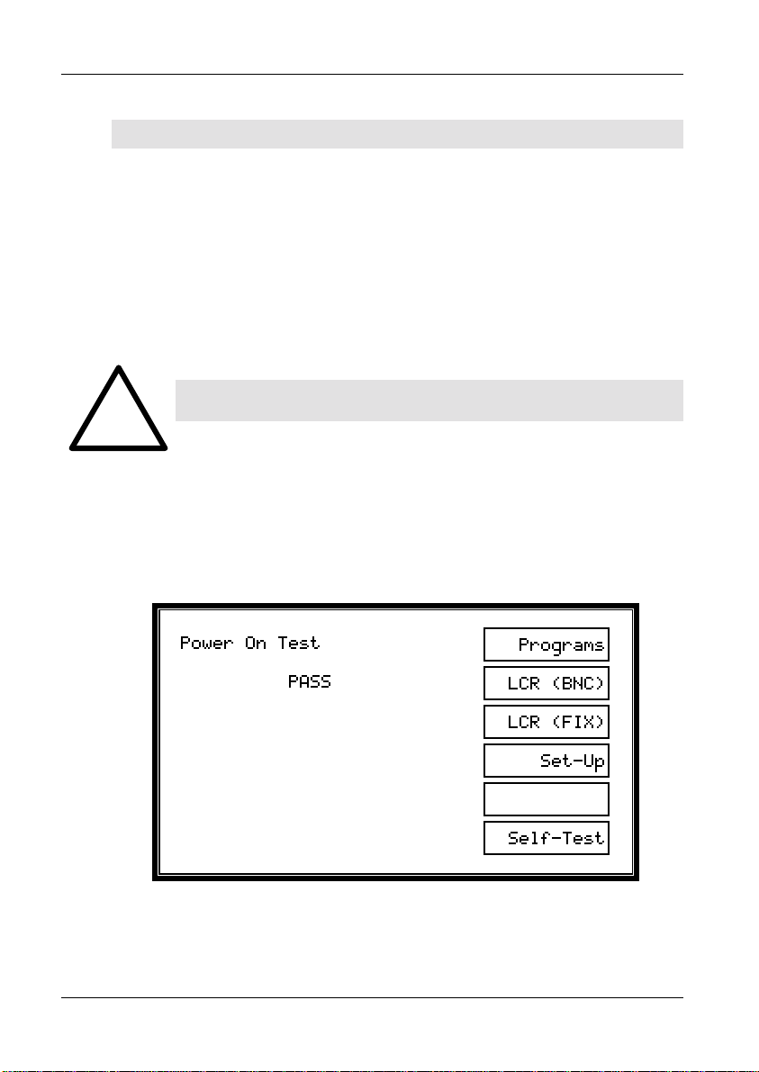
When the power-on self-test has finished, you should see the following display:
The tester is now at the top-level menu, and the softkeys allow you to select
which of the five main functions you require:
PAGE 2-10 VOLTECH ATI USER MANUAL

GETTING STARTED
Programs is used when running test programs in production test
mode.
LCR (BNC) / (FIX) enable the tester to behave like a component analyzer,
continuously updating front-panel readings. See chapter
6 for more information no the LCR front-panel mode.
Set-Up is used to group download programs from a Server PC to
the permanent store of the tester and to set up the
options within the tester.
Self-Test is used to perform a thorough self-test.
A detailed explanation of the operation of the ATi that follows pressing the
Execute, Program and Self-Test keys is given later in this chapter.
VOLTECH ATI USER MANUAL PAGE 2-11

GETTING STARTED
2.2.2 Installing the PC Editor
Connect the tester's auxiliary port to a spare COM port on the PC as shown.
The type of connector on the PC will determine the cable that you use. For
most PC’s this will be a 9-pin female (PC) to 9-pin female (ATi).
Auxiliary port
COM port
Switch on the power supply to the PC
Before attempting to install the Editor, check that your PC satisfies the
following hardware requirements:
PC processor 486 or better
Memory 4MB minimum
Hard disk space 2MB minimum
Operating system Windows 95 or newer
Supported screen resolutions 640 x 480, 800 x 600
1024 x 768, 1280 x 1024
CD-ROM drive x2 minimum speed
To install the Editor software, place the ATi CD-ROM supplied with your tester
into the CD-ROM drive of the computer and follow the on-screen instructions.
PAGE 2-12 VOLTECH ATI USER MANUAL

GETTING STARTED
1. The set-up program will suggest a directory in which to place the Editor files:
C:\Program Files\Voltech Instruments\Voltech AT Editor
This directory will be created if it does not already exist. If you want to place
the files elsewhere, browse to another directory.
If you have a previous version of the Editor software already installed on your
PC, the procedure outlined above may also be used to install a new version.
None of your program files will be lost. The same Editor program is used for all
AT Series testers (excluding the discontinued AT3500 and AT1000).
PC COM Port Configuration
When the installation of the Editor has been completed, you will see the Editor
icon in the program group ‘Voltech Software’. Double-click with the left mouse
button on the Editor icon to start the program.
Initially, configure the Editor to use the chosen COM port:
1. From the top-level
‘Setup’ menu,
select
‘Communications’.
2. In the dialogue
box shown here,
select he PC
communications
port that is
connected to the
tester.
WARNING: If the chosen ‘COM’ port is reserved by another
Windows application, an error message will appear. You
i
should select another port.
VOLTECH ATI USER MANUAL PAGE 2-13

GETTING STARTED
2.2.3 Installing the PC Server
Check that your PC satisfies the following hardware requirements:
PC processor 486 or better
Memory 4MB minimum
Hard disk space 3MB minimum
(Note: 3MB does not include disk space required
for storing programs or test results)
Operating system Windows 95 or later
CD-ROM drive x2 minimum speed
To install the Server software, follow the same basic instructions as for the
Editor. The Server is often installed on a different PC to that which will be used
for the Editor, depending on your production needs. A Server PC needs to be
permanently connected to the ATi only if you wish to store test results or use a
central program store rather than the ATi’s own memory.
Server Hardware Connections
In some applications, you may wish to position the Server PC some distance
away from the tester, which will require a cable longer than the one supplied.
The AT Series Server port connector details are shown in Chapter 8, to enable
you to make up a cable of the length you require.
To use more than one or two AT Series Testers with the same Server host PC,
an intelligent COM port expansion card will be required. The server application
supports the DIGIBOARD XE eight-channel device.
PAGE 2-14 VOLTECH ATI USER MANUAL

GETTING STARTED
Programs/
Results
Programs/
Results
Programs/
Results
Before installing an expansion card, ensure that the PC is switched off and that
you follow all of the manufacturer’s instructions. All supporting software must
also be installed before attempting to configure the Server application.
The same server program is used for all AT Series Testers (excluding the
discontinued AT3500 and AT1000).
VOLTECH ATI USER MANUAL PAGE 2-15

GETTING STARTED
PC COM Port Configuration
Before proceeding any further, check within the Windows Control Panel to
ensure that the desired COM Port(s) are recognized by Windows.
Example of setup for DIGIBOARD XE
Server Software Set-up
When the installation of the Server has been completed, you will see the
Server icon in the program group ‘Voltech Software’. Double-click with the left
mouse button on the Server icon to start the program.
Before you can use the Server, the PC communication channels must be
assigned for each tester connected.
PAGE 2-16 VOLTECH ATI USER MANUAL

GETTING STARTED
When the Server is executed for the first time, the following dialogue will be
displayed:
A check box 'Do not display this dialogue at Startup' exists to prevent it from
being displayed each time the Server application is launched. When this
option is activated, this dialogue box can be accessed via the ‘Setup’,
‘Communications...’ menu.
To assign a particular AT Series Tester to a COM port:
1. Select the communication port to which your tester is connected from
the COM PORT selection box.
2. Click on the ADD button to append your connection to the current
connection list.
3. To remove a current connection, select it from the list and then click
on the REMOVE button.
IMPORTANT: You must have at least one AT Series
Tester connection to use the program transfer or
i
VOLTECH ATI USER MANUAL PAGE 2-17
results storage functions of the Server application.
GETTING STARTED
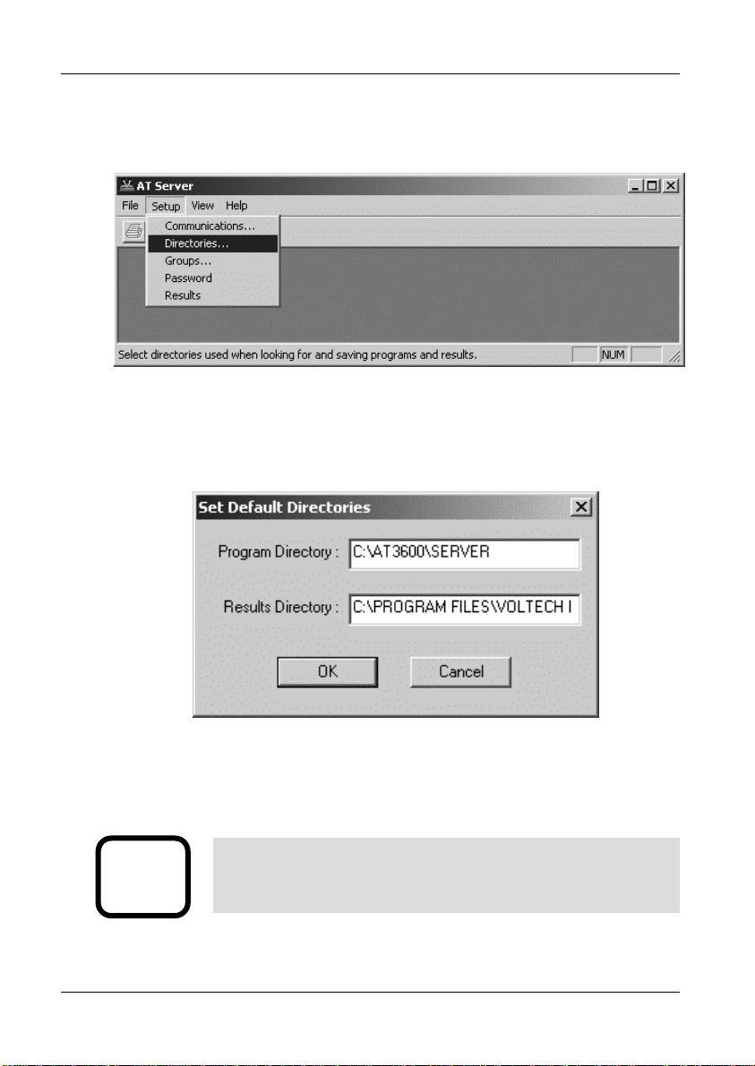
The final stage of setting up the server involves specifying the file location
paths.
The directory set-up dialogue will prompt you with the current directory.
Change these settings if you wish to nominate your own program and results
storage directories.
The setting of program path directories may be altered at any time.
The directory set-up dialogue may be found under the SETUP section of the
menu bar.
IMPORTANT: If you change the factory default settings,
remember that the Server will only look in the directories
i
PAGE 2-18 VOLTECH ATI USER MANUAL
specified for test programs or results.

GETTING STARTED
A
2.3 QUICK START TUTORIAL
2.3.1 Introduction
After you have installed your ATi and its associated Editor and Server PC
software packages as described in the previous section you may wish to follow
through this tutorial before trying to create any programs for actual use.
The purpose of this tutorial is to familiarize you with the process of creating a
schematic and a test program using the editor.
Creating a Schematic of a 2-Winding, 4-Terminal Sample Transformer
This tutorial describes a method of setting up the tester to test a two winding
transformer with the following specification:
C
B
Before proceeding ensure that the tester is connected to the Editor PC as
described in earlier in this chapter.
VOLTECH ATI USER MANUAL PAGE 2-19
Resistance of winding AB (59 to 73Ω)
Resistance of winding CD (59 to 73Ω)
Inductance of winding AB (>3H)
D

GETTING STARTED
2.3.2 Drawing the Transformer Schematic
At the PC, double-click on the editor icon to start the PC Editor. The first thing
to do is to ‘draw’ a schematic of the transformer to be tested.
1. Using the left mouse button, click on ‘Schematic’ on the top Level
menu bar, and select ‘Add Winding’ from the menu.
You will now see a winding with two terminals, floating below the
mouse pointer.
2. Place the winding on the left hand side of the screen and press the
left mouse button.
3. A dialogue box will ask you to name the terminals of the winding; the
cursor will be in the box for Terminal 1. Type the name of the
Terminal 1 (e.g. ‘A’).
Press TAB to move to the Terminal 2 box, and type the name of the
second terminal (e.g. ‘B’) in that box. Then click OK or press [Enter].
PAGE 2-20 VOLTECH ATI USER MANUAL

GETTING STARTED
4. Repeat steps 1-3 to create a second winding. This time place the
winding on the right hand side of the screen, a mirror image of the
first winding, and use different terminal names (e.g. ‘C’ and ‘D’). The
screen should then look like this:
Now you must connect the windings to the test nodes of the tester:
Place the mouse pointer over terminal A; press and hold the right
button. Continue holding this mouse button down and drag the mouse
pointer to test node 9. Release the button. A wire will now connect terminal A
to test node 9. Repeat this procedure to connect the other three terminals, B,
C and D to nodes 7, 10 and 8. The screen should now look like this:
RIGHT MOUSE
CLICK TO DRAG
CONNECTIONS
You have now created a schematic layout of a four terminal transformer.
mouse
VOLTECH ATI USER MANUAL PAGE 2-21

GETTING STARTED
2.3.3 Creating the Test Program
After creating the transformer schematic, you may now create an example
program, containing the following four tests:
Resistance of winding AB (59 to 73Ω)
Resistance of winding CD (59 to 73Ω)
Inductance of winding AB (>3H)
Turns ratio AB to CD (1:1 ± 2%)
(It is probable that the actual program used to test such a transformer in
production would be the same four tests, plus an additional insulation
resistance test to check for winding-to-winding isolation.)
First, set up the program options. From the top-level menu bar select:
Program > Options
The following dialogue box will appear:
PAGE 2-22 VOLTECH ATI USER MANUAL

GETTING STARTED
By clicking with the mouse, enable the following option
‘Send Results to Server’
In the Fixture ID box, enter the name:
‘UNIVERSAL’
Click on ‘OK’ or press [Return] to accept and close the dialogue box.
You can now move on to create the program:
1. From the top-level ‘Program’ menu, select ‘Edit’. The screen will now
be made up of three Windows:
Top left: The schematic window showing the two windings.
Right: The available tests window listing all the tests available
on your tester. (If the tester is connected any tests not
available will be greyed out).
Lower left: The program window displaying the tests programmed so
far.
By double-clicking the left mouse button, select ‘R Winding Resistance’ from
the ‘Available Tests’ window.
VOLTECH ATI USER MANUAL PAGE 2-23

GETTING STARTED
The following dialogue box will appear.
1. Initially enter the terminal names. Input ‘A’ as the high terminal and
‘B’ as the low terminal, moving between the fill-in boxes using the
TAB key.
Click anywhere over the High and Low Terminal drop-down boxes to
see a list of the available terminals.
2. Now enter the resistance limits. This can be done in four ways:
% Click on this button to enter a nominal value with a percentage
tolerance (for example, 66Ω with 10% tolerance),
>< Click on this button to enter minimum and maximum values (for
example, 59Ω and 73Ω),
> Click on this button to enter just a minimum value (for example, >
59Ω),
< Click on this button to enter just a maximum value (for example <
73Ω).
In this example, >< limits will be used:
The ‘Ohm’ units button is selected by clicking with the mouse.
PAGE 2-24 VOLTECH ATI USER MANUAL

GETTING STARTED
3. If the "User Offset Enabled" check box is checked, a value can be
entered into the edit box. The value entered (in the units shown) is
then added to any results returned from the AT tester. This function
can be used to adjust for measurement fixture effects that cannot be
compensated for or to compensate the fixture manually so a
compensation stage is not required to obtain the correct readings.
4. Click on the ‘OK’ button. The test and its parameters will now appear
in the ‘Program’ window.
5. Again by double clicking the left mouse button, select ‘R Winding
Resistance’ from the ‘Available Tests’ window. At the dialogue box,
enter the data as before; this time for the second winding:
Integration (Leave as the default - Medium)
VOLTECH ATI USER MANUAL PAGE 2-25

GETTING STARTED
Click on the ‘OK’ button. Again, the test and its parameters will appear in
the ‘Program’ window.
6. Now, by double-clicking the left mouse button, select ‘LS Inductance
(Series Circuit)’ from the ‘Available Tests’ window.
At the dialogue box, enter the data required for the inductance test:
Signal 1V (again, choose the V units button by clicking
with the mouse)
Frequency 50Hz
Integration (Leave as the default - Medium)
High terminal A
Low terminal B
Click on the ‘ > ‘ button to select a minimum limit only, and enter:
High terminal C
Low terminal D
Minimum 59Ω
Maximum 73Ω
Minimum 3H
PAGE 2-26 VOLTECH ATI USER MANUAL

GETTING STARTED
The "User Offset Enabled" check box has the same function as before
but in units of inductance.
Click on the ‘OK’ button. Again, the test and its parameters will appear
in the ‘Program’ window.
7. Finally, by double-clicking the left mouse button, select ‘TR Turns
Ratio’ from the ‘Available Tests’ window.
At the dialogue box, enter the data required for the turns ratio test:
Voltage 1V
Frequency 50Hz
Integration (Leave as the default - Medium)
The AT measures the turns ratio between ‘primary’ and ‘secondary’ windings;
and allows the possibility of applying the test voltage to a third ‘energized’
winding. For this example, the primary and energized windings are the same:
Energized high terminal A
Energized low terminal B
Primary high terminal A
Primary low terminal B
Secondary high terminal C
Secondary low terminal D
Using the default ‘ % ‘ type of limits, enter:
Primary: Secondary 1:1
Neg 2%
Pos 2%
VOLTECH ATI USER MANUAL PAGE 2-27

GETTING STARTED
Click on the ‘OK’ button. Again the test and its parameters will appear in the
‘Program’ window.
PAGE 2-28 VOLTECH ATI USER MANUAL

GETTING STARTED
The lower-left window should now contain the complete program. The scroll bars
in this window enable you to view each test in the program in turn to check that it
is correct.
The Editor will not allow a program to be run in the AT unless it has previously
been saved:
From the top-level menu bar, select
Part > Save As
VOLTECH ATI USER MANUAL PAGE 2-29

GETTING STARTED
At the dialogue box,
type in
TUTORIAL
as the part name
Click on the OK button to close the dialogue box and save the test program in
the Editor default directory.
2.3.4 Running the Program from the Editor
The following section describes how to run a test program from the Editor. To
do this you must first create a program, which includes only the test options
installed in your tester.
Having created both the transformer schematic and the test program, the
program is now ready to run on your tester under the control of the Editor.
PAGE 2-30 VOLTECH ATI USER MANUAL

GETTING STARTED
Before proceeding further, make sure that the interface cable between the
tester's Auxiliary Port and the selected PC COM port is correctly fitted, and that
the COM Port is correctly configured in the editor (see page 2.14).
Ensure that the tester has been switched on.
To run the program:
1 From the top-level menu bar, select: Tester > Download Program
The Editor will now download
the test program to the
tester. After a few seconds,
you should see a message
to say that the download was
successful.
If you see a message
indicating that the download
has failed, check your cable/COM Port connections and try again. If the
download continues to fail, reboot your PC and try again.
The front panel of the AT will now display:
2 This allows the program to be stored on the AT by pressing the softkey next
to 'Local Save'. See section 2.3.4. for a description of running the
program on the transformer tester.
VOLTECH ATI USER MANUAL PAGE 2-31

GETTING STARTED
3 For now, run the program from the editor software and ignore the AT display:
Again, from the top-level menu bar, select:
Tester > Run Program
The test program will now begin execution. When it is finished, you will see
a dialogue box containing the results of the test.
If the transformer had been connected up as in the schematic to nodes 7,
8, 9, and 10 then the results might be:
If no transformer is fitted, the results will have no meaning, but you have now
successfully installed the ATi and the Voltech AT Editor software.
The results window will give you the options to:
1. Print the test results.
2. Re-run the test program.
3. Close the window.
Closing the window will return you to the top-level menu.
PAGE 2-32 VOLTECH ATI USER MANUAL

GETTING STARTED
2.3.5 Server Quick Start
Transferring the Program to the Server
The Voltech Server software is supplied with every AT Series Tester. The use
of the Server software is required for handling and storage of test results and
is recommended for handling large numbers of different test programs.
Having created, saved and tested the program TUTORIAL using the Editor,
you are now in a position to run it again on your AT Series Tester, but this time
using the Server. The procedure for transferring the program to the Server
archive will depend on where you have installed the Editor and Server
programs.
Editor and Server on Separate PC’s
In many situations the Editor and Server can be installed on separate PC’s (as
shown in the illustration earlier). In this situation, the AT is used to perform the
transfer.
Before proceeding further, make sure that all the following have been set up:
• The interface cable between the tester’s auxiliary port and the selected
COM Port on the Editor PC is correctly fitted, and that the COM Port is
correctly configured in the Editor software (see the Editor quick start
earlier).
• The interface cable between the tester’s server port and the selected
COM port on the Server PC is correctly fitted, and that the COM Port is
correctly configured in the Server software (see earlier).
• Both the Editor and the Server software packages are running.
• The tester is still powered on as described above.
VOLTECH ATI USER MANUAL PAGE 2-33

GETTING STARTED
To transfer the program, from
the top-level menu bar, select:
Server > Download Program
The Editor will now download
the test program to the Server
using the AT.
After a few seconds, you should see a message to say that the Download was
successful.
If you see a message indicating that the download has failed, check your
cable/COM Port connections and try again. If the download continues to fail,
reboot both PC’s and try again.
Editor and Server Both on a Single PC
If the Server and Editor are installed on the same PC, the easiest way to
transfer the test program to the Server is to use the Save As menu in the
Editor:
From the top-level menu bar, select
Part > Save As
PAGE 2-34 VOLTECH ATI USER MANUAL

GETTING STARTED
At the dialogue box, type in the part name
TUTORIAL
as before, and change
the directory to the
one selected for
program storage
e.g.
C:\AT3600\SERVER
when the Server was
installed.
Click on the OK button to close the dialogue box and save the test program in
the Server program directory.
The next section of the tutorial demonstrates running the program on the AT
from the archive on the server. Before proceeding to that section, if the Server
and Editor are using the same COM-Port on the single PC, re-allocate the
COM-Port from the Editor to the Server:
• Close down the Editor by clicking on
• Part > Exit in the top-level menu.
• Start the Server by double clicking on its Windows icon.
• Configure the COM-port as shown earlier.
• Remove the cable between the AT auxiliary port and the PC COM-port.
• Connect the cable between the AT Server port and the PC COM-port
VOLTECH ATI USER MANUAL PAGE 2-35

GETTING STARTED
2.3.6 Running a Program on the Tester
Having stored the program in the Server archive, it is now possible to run the
program on any AT that is connected to the Server.
Before proceeding further make sure that the Server is running, with the
interface cable correctly fitted between the tester’s server port and the selected
Server PC COM port, and the COM port is correctly configured in the Server
software.
At this point the tester should still be powered on, the display should still show
a ‘last transformer’ message, produced when the test program was run from
the Editor. It will be similar to the following:
Before running any new test program, return the tester to the top-level menu
by pressing the ‘Finish‘ softkey.
PAGE 2-36 VOLTECH ATI USER MANUAL

GETTING STARTED
Use the following sequence of key presses to ensure that the AT is configured
to use the Server as the source for test programs:
1 From the top-level menu, choose ‘Set-Up’ to change to the following
display:
2 Press the softkey ‘Set-Up’ and at the following display:
3 Press the ↓ softkey until the third line shows the words ‘Program Store’:
VOLTECH ATI USER MANUAL PAGE 2-37

GETTING STARTED
4 If, as shown above, the origin is INTERNAL, then press the softkey
‘Server’, so that the third line reads as follows:
5 Press the softkey EXIT to return to the ‘Set-Up’ display and then press the
EXIT softkey, again, to return to the top-level display.
PAGE 2-38 VOLTECH ATI USER MANUAL

GETTING STARTED
Then, use the following sequence of key presses to run the test program for
the part ‘TUTORIAL’:
1. Press the softkey ‘Programs’ to display:
2. The program name can now be chosen from the list of programs available
on the PC Server.
If the list of programs fails to appear after a few seconds, check that the AT
Server is running, the COM port and file folder are configured correctly and
that the cable from the AT Server port is correctly fitted to the PC.
3. Use the
↑↑↑↑ and ↓↓↓↓ keys to select the program and press the ‘Run’ softkey.
VOLTECH ATI USER MANUAL PAGE 2-39

GETTING STARTED
4. When the download has been successfully completed, you will see a
message to fit the fixture similar to the following:
5. As the fixture is already fitted, and compensation is not required with the
sample transformer, simply press the ‘No Comp’ softkey to move on to
the ‘Run-Finish’ display:
PAGE 2-40 VOLTECH ATI USER MANUAL

GETTING STARTED
6. Press the ‘Run’ softkey to start program execution. As the program is
running, the RUN indicator (the yellow LED to the left of the display) will
be illuminated, and the display will indicate the test currently being
executed:
At the end of program execution, the PASS indicator (the green LED to the left
of the display) should be illuminated, and the display should show:
VOLTECH ATI USER MANUAL PAGE 2-41

GETTING STARTED
7. Press the RUN softkey several times to repeat the program execution.
On each run of the program, the test results should be passed back to the
Server, where they may be viewed in the ‘On-line Monitor’ window
If batch statistics have been enabled within the Server, you will see the
summary batch results window.
PAGE 2-42 VOLTECH ATI USER MANUAL

GETTING STARTED
Test results may also be reviewed at any time via the tester’s front-panel
results listing screen, which is accessible from the ‘Run-Finish’ display by
pressing the ‘Results’ softkey (see below).
The results listing screen displays all completed tests giving test number, type,
result in both value and pass or fail, and status error (for a description of status
error codes, see chapter 3). The listing may be printed by pressing the PRINT
soft-key in the same style as the standard results.
VOLTECH ATI USER MANUAL PAGE 2-43

GETTING STARTED
After several program runs, press the ‘Finish’ softkey to return the tester to the
top-level display.
This is the end of the step-by-step tutorial, which forms only a very brief
introduction to the features available on your ATi. Please study and browse
through the rest of this manual (or the on-line help for the Windows software)
to get the best from your transformer tester.
The next section lists more features of the tester that you may wish to
investigate yourself at this point, before you try to create ‘real’ programs for
production use.
PAGE 2-44 VOLTECH ATI USER MANUAL

GETTING STARTED
2.3.7 Storing Programs
For everyday production use, programs should be stored either:
• on a PC running the server software which will be permanently connected
to the AT.
• in the tester’s own memory.
Method 1: Using a permanently connected PC server has been described in
the previous ‘Getting Started’ section.
Method 2: Using the ATi’s own internal memory as described here:
The programs can be stored within the tester even when it is switched off.
Once a program is stored, the tester may be used without PC Editor or Server
software.
To operate the tester in this way, the origin of the tester’s programs must be
set to the local program store.
On the tester, at the ‘Program mode’ display, under the softkey SET-UP,
change the ‘Origin’ to ‘LOCAL’.
This is described in section ‘Getting Started’
Working Without a Server – Storing a SINGLE Program
A single program may
be stored in the AT
using the PC Editor.
Once a program has
been entered using the
Editor and downloaded
to the tester, the tester
will display:
VOLTECH ATI USER MANUAL PAGE 2-45

GETTING STARTED
Press ‘Local Save’, and the program that has been downloaded from the PC
editor will be saved in the tester’s local program store. Note that any programs
previously stored in the tester will be lost.
All PC connections to the tester may now be removed.
To run the program at any time, return the tester to the top-level display, press
‘Programs’ at the top-level display, choose the program from the list of
programs and press the ‘Run’ key and continue as before.
Storing Groups of Programs Inside the ATi Using the PC Server
Rather than dealing simply with individual programs, the AT Server allows you
to create groups of programs, which may be downloaded to the AT tester and
then used individually from within the local tester facilities.
Having executed programs from the Server, as it is connected to the tester,
you may want to download a group of programs to the tester, so the tester can
be used in a stand-alone situation. To do this, use the Server software to
create a named group of programs.
Ensure that the Server is still running and connected to the tester, as
described above.
PAGE 2-46 VOLTECH ATI USER MANUAL

GETTING STARTED
On the tester, at the top-level display, choose ‘Set-Up’. Then, at the ‘Set-up’
display, press the ‘Groups’ softkey , followed by the ‘List’ softkey to obtain a list
of program groups available for download.
Select the group to be downloaded to the tester and press ‘Enter’. If the group
download is completed successfully, you will see the following display:
VOLTECH ATI USER MANUAL PAGE 2-47

GETTING STARTED
At this point, unless you wish to archive measured results on the Server, the
Server connection may be removed.
Return to the tester’s top-level display by pressing the ‘Continue’ softkey,
change the set-up of the tester to use the internal program store instead of the
Server, press the ‘Programs’ softkey, and you will find the downloaded group
programs available to you locally on the tester.
Results Analysis
You may wish to use another application for further analysis of test results sent
back to the Server:
Close down the Server so that you may have full access to the results file.
The results will be stored in the directory chosen for results when the Server
was installed earlier in a file with a name similar to
C2311096.ATR,
where ‘C2311096’ is a coded version of the date, and ‘.ATR’ is the file
extension used by the AT Server for results files.
As an example, use the procedure outlined in section 4 of this manual to
import the results into an Excel spreadsheet.
PAGE 2-48 VOLTECH ATI USER MANUAL

GETTING STARTED
2.4 SELF-TEST
Self-test is a sequence of checks made by the tester to ensure the unit is
functioning correctly. Self-test checks that all of the relays in the 20-way matrix
are opening and closing properly and checks that all the test signal sources
and measuring circuits are working properly and within their calibration limits.
Once the tester has warmed up for an hour, you may run self-test at any time
by pressing the SELF-TEST softkey in the top-level menu.
Before commencing self-test, please ensure that there is nothing
touching any of the test nodes on the top surface of the tester. In
!
VOLTECH ATI USER MANUAL PAGE 2-49
particular, remove all test fixtures and transformers and anything
connected to the four BNC terminals.

GETTING STARTED
As the self-test is running, the front-panel display will indicate progress using a
horizontal bar:
At the end of the self-test, you should see the following screen:
PAGE 2-50 VOLTECH ATI USER MANUAL

GETTING STARTED
If there is a failure at any point in the self-test, you will see a display similar to
the one below:
The message shown on the lower two display lines will depend on what
caused the failure.
In the unlikely event that your tester continues to fail, please make a careful
note of the failure message and error codes, which may be accessed by
pressing ‘Details’ at the above display, and contact your Voltech supplier
immediately. (For more detail on AT error codes, see chapter 3.)
VOLTECH ATI USER MANUAL PAGE 2-51

GETTING STARTED
2.5 PRODUCTION MODE
This is the normal operating mode of the ATi when used for production testing
of transformers.
Before you try to use the tester in production mode, make sure that all of the
following have been carried out:
1. Test programs have been created for the transformers that you wish to
test.
2. Either the programs are archived in the Server, which is connected to the
tester and running, and the tester has been set up to use the Server as
the Program Store,
or the programs have been downloaded into the tester, which has been
set up to use its internal memory as the Program Store.
3. Fixtures have been created for the transformers you wish to test.
Note:
If you have a footswitch fitted to the remote port on the tester, pressing it will
take the same action in production mode as pressing the upper softkey.
For text entry (such as the name of a program or the serial number of the
transformer under test), you may optionally use a barcode reader connected to
the tester's rear panel barcode port.
PAGE 2-52 VOLTECH ATI USER MANUAL

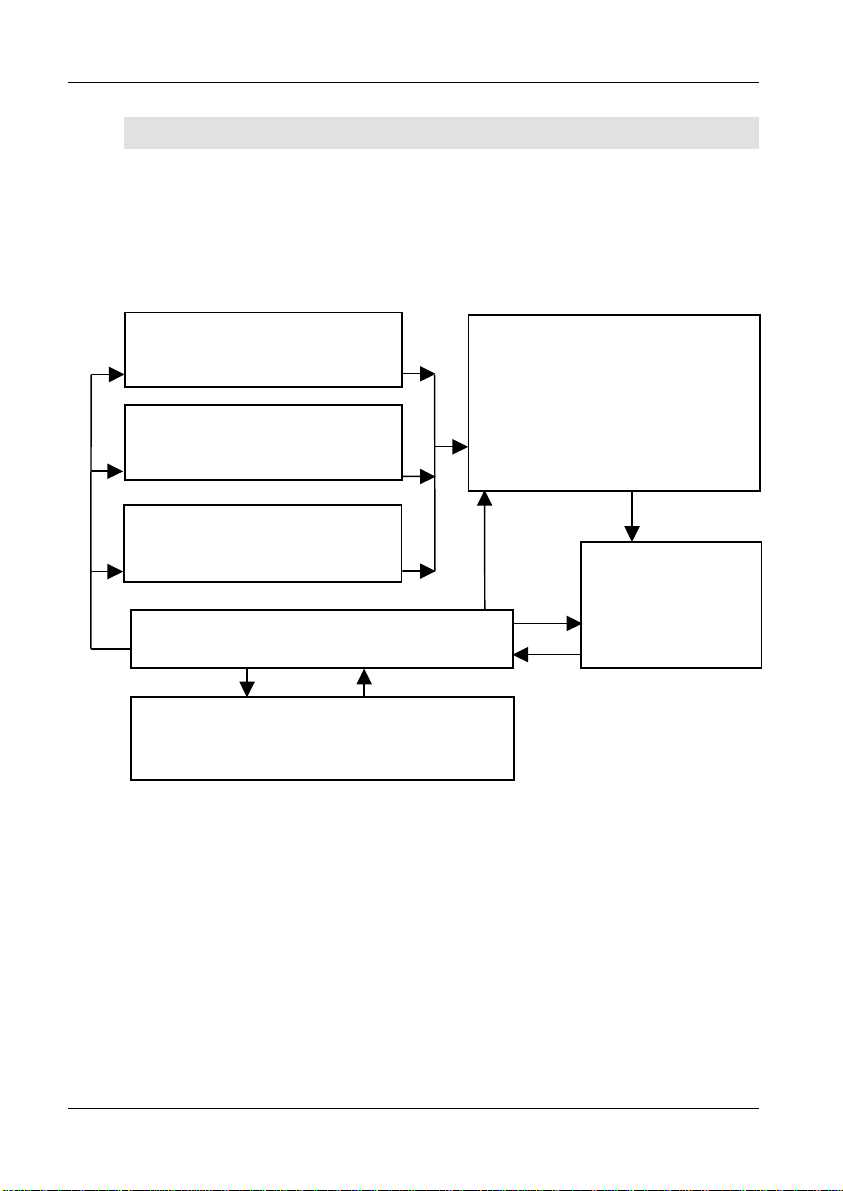
2.5.1 Production Mode With No Options Enabled
Top-level
Display
Select
Programs So ft-key
For simple test programs, (where
none of the following options are
enabled: batch number, operator
number or serial number), the flow
diagram shown on the left
summarizes production mode
operation.
Select
Test Program
to Run
Fit Fixture
NO
COMP
Compensate
Fixture?
GETTING STARTED
COMP
Fixture
Compensation
RUN-FINISH
Menu
FINISH
Run or
Finish?
RUN
Measurements
VOLTECH ATI USER MANUAL PAGE 2-53

GETTING STARTED
At the top-level display, press softkey 1 ‘Programs’.
The program to be run may now be chosen from a list of programs available
on the PC Server or in the ATi’s own memory (i.e., local programs), entered by
swiping a barcode, or created directly from the front panel by selecting ‘* New
program *’ and pressing the ‘Set-Up’ softkey (see chapter 6).
Once the test program to be executed has been selected, pressing softkey 1,
‘Run’, produces the following display:
PAGE 2-54 VOLTECH ATI USER MANUAL

GETTING STARTED
FIXTURE1 is the name given as the ‘Fixture ID’ in the Editor software
‘Program options’ dialogue (see chapter 3) or under program options in front-
panel program mode (see chapter 6).
Press ‘Compensate’ or ‘No Comp’ as required.
Note: For fixture compensation, see later in this chapter.
Place the component to be tested in the fixture and press the ‘Run’ softkey,
touch one of the run-pads, or press the footswitch.
VOLTECH ATI USER MANUAL PAGE 2-55

GETTING STARTED
After the measurement, remove the component and place it in the ‘Pass’ or
‘Fail’ bin, as appropriate.
Continue in this way until each component in the batch has been tested, then
press ‘Finish’.
2.5.2 Error Messages
Server Program Store Error
Possible Causes:
Faulty cable
The cable from the AT Server port to the Server PC has a broken wire or is not
plugged in correctly.
COM port
The COM port has not been set up in the Server application.
Server not running
Either the Server PC is not powered on, or the Server application is not
running.
PAGE 2-56 VOLTECH ATI USER MANUAL
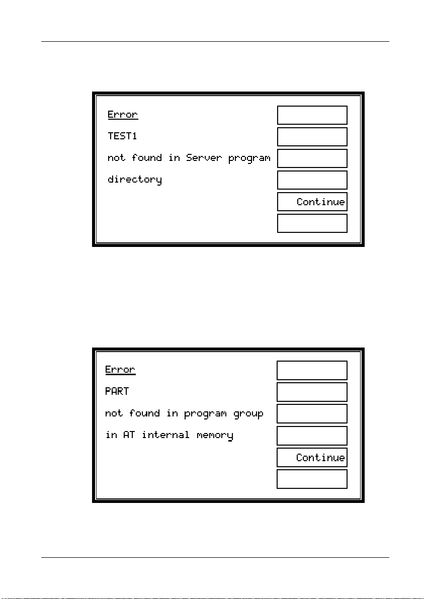
GETTING STARTED
If the Server software and connection to the Server PC are working correctly,
the following error screen may appear:
Cause:
The directory set up in the Server application as the location of test programs
does not contain a test program file with the requested name.
Local Program Store Error
VOLTECH ATI USER MANUAL PAGE 2-57

GETTING STARTED
Cause:
The requested part number is not resident in the group of programs that have
been downloaded into the AT.
At all the above displays, pressing the ‘Continue’ softkey will take you back to
the top-level display.
2.5.3 Indications Displayed While Tests Are Running
Where ‘1’ represents the position of the test within the test program.
The operator may terminate the measurements at any time by pressing the
‘Stop’ softkey. Alternatively, you may use the STOP input signal on the tester’s
remote port, which may be connected, for example, to an emergency stop
switch.
As the measurements proceed, the test number will increment.
PAGE 2-58 VOLTECH ATI USER MANUAL

GETTING STARTED
The ‘Run-Finish’ display is seen after a component has been tested. The front-
panel LED (green = ‘Pass’, red = ‘Fail’), the output lines of the remote port and
the LCD indicate the pass or fail result of the previously tested transformer, so
that the operator may place it in the appropriate ‘Pass’ or ‘Fail’ bin.
Results are also sent to the Server at this time, if so enabled in the Editor
program options, and all previous test results may be reviewed on the results
listing screen, which is accessible directly on the front panel via the ‘Results’
softkey (see below).
VOLTECH ATI USER MANUAL PAGE 2-59

GETTING STARTED
Results listing screen
Note that the total and failed number of transformers tested displayed are reset
when the test batch number is changed or a new test program is run.
If the STOP softkey is pressed or the STOP input of the remote port is held
low, the ATi will immediately stop testing. STOP will be shown on the display,
all LED’s will be off, and no results will be reported back to the Server.
2.5.4 Re-measuring Fixture Compensation
PAGE 2-60 VOLTECH ATI USER MANUAL

GETTING STARTED
If you think that fixture compensation needs to be re-measured at any time, at
the above display, press the ‘Settings’ softkey to reveal:
Press ‘Compensate’ to repeat the fixture compensation measurements, or
‘Back’ to return to the RUN-FINISH display without re-compensating.
2.5.5 Execute Mode With Options Enabled
As stated in the following chapter of this user manual, test programs may be
created with any of the following three options enabled or disabled:
• Operator name
• Batch number
• Serial number
In each case, if an option is enabled, the data entered by the operator for that
option is included with the results that are sent back to the Server. This
additional data is then available to be used as you wish; for example, it may be
included in your production reports.
Note that these options are part of the program, not global settings of the ATi,
allowing you to enable different options for each transformer, as required.
VOLTECH ATI USER MANUAL PAGE 2-61

GETTING STARTED
When running programs with any of the above options enabled, there will be
additional displays (depending on which options are enabled) after the ‘Fit the
Fixture’ display and before the RUN-FINISH display.
PAGE 2-62 VOLTECH ATI USER MANUAL

The following flow diagram summarizes the possibilities:
Top-level Display
Select
Programs Soft-key
Select Test Program
to Run
Fit and
Compensate
Fixture
Enter
Operator Name
GETTING STARTED
Enter
Batch Number
Enter
Serial Number
RUN-FINISH
Menu
RUN
Measurements
Enter New
Serial Number
New Batch
New Operator
Re-compensate
FINISH
VOLTECH ATI USER MANUAL PAGE 2-63

GETTING STARTED
Additional displays after entering the part number
PAGE 2-64 VOLTECH ATI USER MANUAL

GETTING STARTED
Use either the keypad or a barcode reader to enter the operator/batch/serial
number, then press the ENTER key on the keypad or the ‘Enter’ softkey.
Cursor softkeys ( ← → ) appear in context, and may be used with the ‘Delete’
softkey to correct mistakes.
Serial Number Entry After the First Transformer
When the serial number option is enabled, after the measurements for each
transformer have been completed, the following display will be seen (with the
fourth display line indicating ‘Pass’, ‘Fail’ or ‘Stop’ as appropriate):
VOLTECH ATI USER MANUAL PAGE 2-65
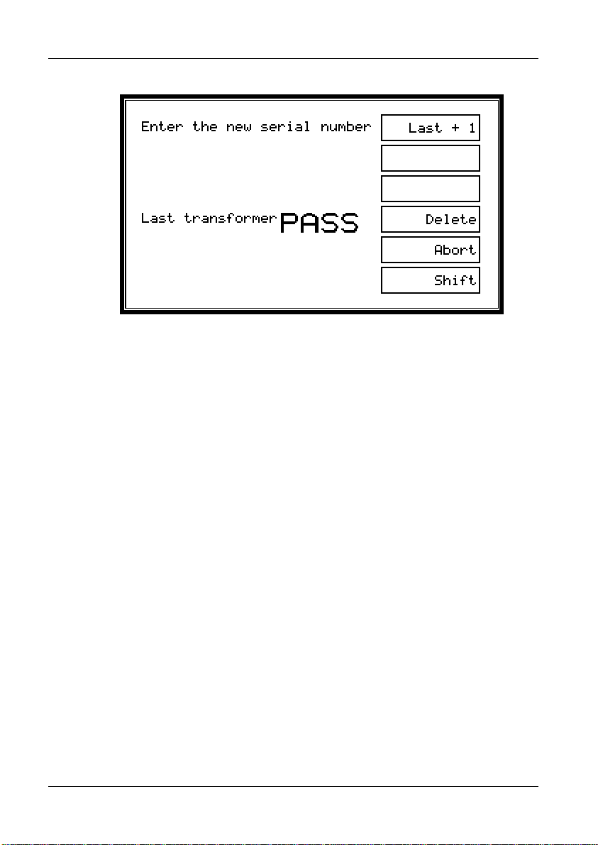
GETTING STARTED
If the next serial number to be used simply follows on in sequence after the
previous one, then press the ‘Last + 1’ softkey (or the touch pads). This will
enter the next serial number automatically and return the display to the RUN-
FINISH selection.
Note: ‘Last + 1’ will be displayed only if the serial number is of the form:
xxxAnnnn
Where ‘xxx’ is a field containing any characters, A is a non-numeric character,
and ‘nnnn’ is a field of all numeric characters.
Both ‘xxx’ and ‘nnnn’ can be of any length, provided that the total serial
number is no more than 20 characters.
When ‘nnnn’ is all 9’s (for example 99), the next number will show ‘nnnn’ as all
0’s (for example 00); the characters ‘xxxA’ will not be changed.
Alternatively, if the next serial number does not follow from the previous one in
sequence, you may use the keypad (or the barcode reader) to type in a new
number.
After typing the new number, press the ENTER key, the ENTER softkey or the
footswitch to return to the RUN-FINISH display.
PAGE 2-66 VOLTECH ATI USER MANUAL
 Loading...