

Page 1
Page 2
1
The installation, service and maintenance of this equipment should be rendered by a qualified and trained
technician. This manual is written specifically for these individuals and is intended for their use. Untrained
individuals who use this manual assume the risk of any resulting property damage or personal injury.
The DiUse system meets the essential safety and health requirements of the European Union. This means that
DiUse can be operated and maintained safely if all safety precautions are considered. However, dangerous
situations can occur due to injudicious or negligent use of the system.
NOTE: The DiUse system is not intended for use with water of unknown quality.
NOTE: The DiUse system is to be supplied with cold water.
WARNING!
Electrical shock hazard! Prior to servicing equipment,
disconnect power supply to prevent electrical shock.
WARNING!
Electrical shock hazard: Located on the electrical cabinet
door and inside the electrical cabinet. The electrical
cabinet may never be opened when the system is
producing water.
WARNING!
If incorrectly installed, operated or maintained, this
product can cause severe injury. Those who install,
operate or maintain this product should be trained in its
proper use, warned of its dangers, and should read the
entire manual before attempting to install, operate or
maintain this product.
CAUTION!
This product is not to be used by children or persons with
reduced physical, sensory or mental capabilities, or lack
of experience or knowledge, unless they have been given
supervision or instruction.
CAUTION!
If the power cord of the unit looks or becomes damaged,
the cord should be replaced by a Voltea service engineer
or similarly qualified person to avoid hazard.
All rights reserved. No part of this publication may be reproduced, stored in a database or retrieval system, published in any form or in any way, electronically,
mechanically, by print, photo print, microfilm or any other means without prior written permission from the manufacturer. All Voltea trademarks and logos
are owned by Voltea B.V. All other brand or product names are trademarks or registered marks of their respective owners. Because we are continuously
improving our products and services, Voltea reserves the right to change specifications without prior notice. Voltea is an equal opportunity employer. DiUse
Owner’s Guide: Copyright © 2018
EUROPEAN OFFICE
Wasbeekerlaan 24
2171 AE Sassenheim, Netherlands
+31(0)252.200.100
US OFFICE
1920 Hutton Court #200
Farmers Branch, TX 75234
+1(469)620.0133
Page 3

2
CONTENTS
1 DiUse Manual .................................................................................................................................. 4
1.1 General safety precautions ..................................................................................................... 5
2 Liability and Warranty ..................................................................................................................... 5
2.1 Liability .................................................................................................................................... 5
2.2 Warranty ................................................................................................................................. 5
3 Voltea CapDI - Membrane Capacitive Deionization ........................................................................ 5
4 DiUse ............................................................................................................................................... 7
4.1 Features .................................................................................................................................. 7
4.2 Specifications .......................................................................................................................... 7
4.3 Feed water quality .................................................................................................................. 8
5 System Overview............................................................................................................................. 9
6 System Installation ........................................................................................................................ 10
6.1 Packing .................................................................................................................................. 10
6.2 Tools and materials ............................................................................................................... 10
6.3 Module installation ............................................................................................................... 10
6.4 Placing leak sensor ................................................................................................................ 12
6.5 Placing the covers. ................................................................................................................ 12
6.6 Water connections ................................................................................................................ 13
6.7 Powering the system up/down ............................................................................................. 13
6.8 replacement of CIP solution .................................................................................................. 13
6.9 Flushing the module.............................................................................................................. 14
7 System Start Up - Operation ......................................................................................................... 15
7.1 Operation with pressurized tank .......................................................................................... 15
7.2 Operation with atmospheric tank ......................................................................................... 15
7.3 System pump ........................................................................................................................ 16
8 System Control Through LCD ........................................................................................................ 16
8.1 DiUse Screen Navigation Chart ............................................................................................. 17
8.2 Voltea DiUse .......................................................................................................................... 17
8.2.1 Process steps ................................................................................................................. 18
8.2.2 Alarms ........................................................................................................................... 19
8.3 Device info ............................................................................................................................ 20
8.4 System ................................................................................................................................... 20
8.4.1 Setpoints ....................................................................................................................... 21
8.5 User functions ....................................................................................................................... 23
Page 4

3
9 Advance System Functions ........................................................................................................... 23
9.1 Receive data and alarms remotely ....................................................................................... 23
9.2 Connecting to laptop and utilizing docklight ........................................................................ 24
9.2.1 Laptop connection ........................................................................................................ 24
9.2.2 Docklight ....................................................................................................................... 26
9.2.3 Downloading operational data from the system .......................................................... 28
9.2.4 Adding e-mail and telephone users. ............................................................................. 29
9.2.5 Daily summary report ................................................................................................... 29
9.2.6 Remote control through SMS ....................................................................................... 30
10 Changing Flow Restrictors ......................................................................................................... 31
11 Electrical Conductivity Probe Calibration ................................................................................. 32
12 Flushing, Bleaching, Storing and Module Disposal ................................................................... 36
12.1 Flushing the module.............................................................................................................. 36
12.2 Bleaching the module ........................................................................................................... 36
12.3 Storage .................................................................................................................................. 36
12.4 Disposal ................................................................................................................................. 37
13 System maintenance ................................................................................................................. 37
14 System Components ................................................................................................................. 38
14.1 Electric cabinet ...................................................................................................................... 38
14.2 Valves, switches and pumps ................................................................................................. 38
Appendix ............................................................................................................................................... 39
Flow restrictor color and flow ........................................................................................................... 39
Spare parts list .................................................................................................................................. 39
50% w/w citric acid solution preparation ......................................................................................... 40
P&ID .................................................................................................................................................. 41
Process flow diagram ........................................................................................................................ 42
DiUse installation PFD ....................................................................................................................... 43
Weekly checklist sheet ...................................................................................................................... 44
Page 5
4
1 DIUSE MANUAL
This manual:
• Familiarizes the user with the equipment.
• Explains installation and setup procedures.
• Provides basic programming information.
• Explains the various steps of operation.
• Gives specification information.
Read this manual first: Before you operate DiUse, read this manual to become familiar with the device.
Through this manual, special symbols will appear:
NOTE
Is used to emphasize information related with installation,
operation and maintenance without highlighting any
hazard.
WARNING!
Warning is used to indicate a hazard which could cause
injury or death if ignored.
CAUTION!
Caution is used when failure to follow directions could
result in damage to equipment or property.
The WARNING and CAUTION signs are not meant to cover all possible conditions and situations that may occur
during installation, maintenance and operation. Understand that common sense, caution and careful attention
is always needed.
Before installing be sure to check all applicable plumbing codes and ordinances. Local codes and legislation may
prohibit the discharge of sanitizing or descaling solution to drain. The system and installation shall comply with
applicable state and local regulations.
Always use protective clothing and proper face or eye protection when handling chemicals and tools.
The CapDI system meets the essential safety and health
requirements of the European Union. This means that the
system can be operated and maintained safely if all safety
precautions are observed. However, dangerous situations can
occur due to injudicious or negligent use of the CapDI system.
If a UL mark is attached to the system, then it has performed
to UL standards and is certified.
The DiUse system conforms to NSF/ANSI 42, for specific performance claims as verified and substantiated by
test data.
Page 6

5
1.1 GENERAL SAFETY PRECAUTIONS
Observe the following general safety precautions:
• Check the proper functioning of the system daily.
• Always replace damaged or defective parts before putting the system into use again.
• Do not make modifications to the system without prior approval of the manufacturer.
• Do not open the electrical cabinet when the system is powered on.
• If chemicals are supplied, the attached safety procedures should be observed.
2 LIABILITY AND WARRANTY
2.1 LIABILITY
Voltea will, under no circumstances be held liable for any consequential damages. The recipient hereby disclaims
all representations and warranties, whether expressed or implied with respect to materials and/or prototypes.
Including without limitation any warranties of non-infringement, merchantability or fitness for merchantability
or fitness for any particular purpose save that such shall have been prepared with reasonable skill and care. The
recipient accepts all risks which may be inherent in its use of materials and/or DiUse system and shall hold
harmless and indemnify each of Voltea and its affiliates officers, director, shareholders, employees and agents
from and against any and all claims, damage, losses or other liabilities that may arise directly and solely from
recipient’s use, storage, handling or disposal of the materials and/or systems.
2.2 WARRANTY
CapDI modules supplied with DiUse have been tested and have a guaranteed performance as they have passed
Voltea’s quality control test (a certificate of analysis will be supplied with each module upon request). Voltea
does warrant workmanship (leakage, connections) of the CapDI module for a period of 1 year from shipment
provided that the CapDI module is operated within the recommended operational limits as provided in the
section 4.2 and 4.3. Voltea does not warrant desalination and other performance aspects of the CapDI modules
within the customer application. Voltea warrants the DiUse for a period of 1 year from shipment provided that
the system is operated in accordance with this manual.
3 VOLTEA CAPDI - MEMBRANE CAPACITIVE DEIONIZATION
The CapDI system uses Capacitive Deionization technology and its function is the removal of ions from the water.
NOTE: The CapDI system does not disinfect water.
CapDI: A tunable water deionization technology that is designed to remove dissolved salts from a variety of
water sources ranging from tap water and brackish groundwater to industrial process water. CapDI achieves this
at a lower economic cost and reduced environmental impact than any other available technology.
Page 7
6
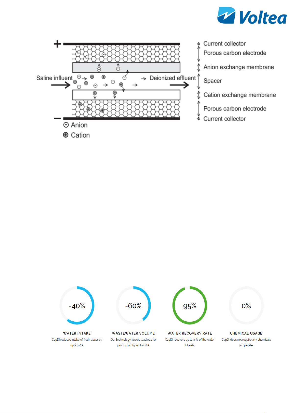
A CapDI module consists of a housing which contains multiple stacks of parallel unit cells. Each unit cell consists
of two porous carbon electrodes separated from each other by a spacer. On top of the electrodes, ion exchange
membranes are placed. The spacer between the membranes acts as a flow channel to transport the water to be
desalinated.
The water flows through a small electrical field of approximately 1.5 volts that is created over a pair of
electrodes. Dissolved ions are pulled out of the water stream, toward the electrodes. The electrodes are
separated from the water by the membranes that selectively allow only positive or negative ions to pass. CapDI
is effective at removing all type of ions from water (e.g. calcium, sodium, chloride, carbonate).
Uniquely: Our technology is environmentally friendly by its low energy consumption and minimal to no chemical
usage. Thus, allowing any unrecovered water to flow back into the ecosystem safely.
Scalable: Voltea’s technology treats water types ranging from residential consumer appliances to large-scale
industrial plants. Our systems are modular, allowing easy expansion to meet any increased water demands.
Tunable: CapDI is tunable, allowing adjustable TDS reduction between 25% - 95% depending on customer needs.
Eliminating the requirements for blending to achieve a specific water quality. The customer sets their desired
reduction rate and the CapDI maintains this level, continually adjusting itself to account for any fluctuations in
feed water characteristics.
Page 8

7
4 DIUSE
Voltea’s miniaturized version of the CapDI systems, specifically made for the point-of-use applications. DiUse
softens and desalinates brackish water for homes and businesses at an advantage to traditional desalination
technologies due to it being a salt-free, chemical-free alternative. DiUse is ideal for the HoReCa industry
alongside small households.
4.1 FEATURES
• Automated system CIP (Clean-In-Place)
• Voltea’s remote monitoring and control (option)
• Pure outlet conductivity meter (0 – 10 mS/cm)
• Total flow meter (0 – 10 L/min or 0 – 2.6 gpm)
• Built in display
4.2 SPECIFICATIONS
Performance
Produced flow rate*
0.6 – 2.9 L/min (0.2 - 0.8 gpm )
Instant flow rate*
1 - 5 L/min (0.3 - 1.3 gpm)
Salt removal
25 - 95 %
Water recovery
40 - 95 %
System Specifications
Average power requirements
0.13 kW, Single Phase (110 - 240 V AC / 50 - 60 Hz)
System dimensions (L x W x H)
0.32 x 0.43 x 0. 64 m (1’10’’ x 1’5’’ x 2’1’’)
Power output to modules
0 - 65 A / 0 - 2 V DC
Weight**
17kg (37.5 lbs.)
Feed inlet coupling
3/8’’ push fit
Product outlet coupling
3/8’’ push fit
Concentrate/Waste outlet
coupling
3/8’’ push fit
Operational
Requirements
Water feed pressure
3 - 10 bar (44 - 145 psi) System is equipped with a
pressure reducer
Water pressure produced***
≤6,5 bar (95psi)
Operating ambient air
temperature
< 35 ﮿C (95 ﮿F)
Page 9
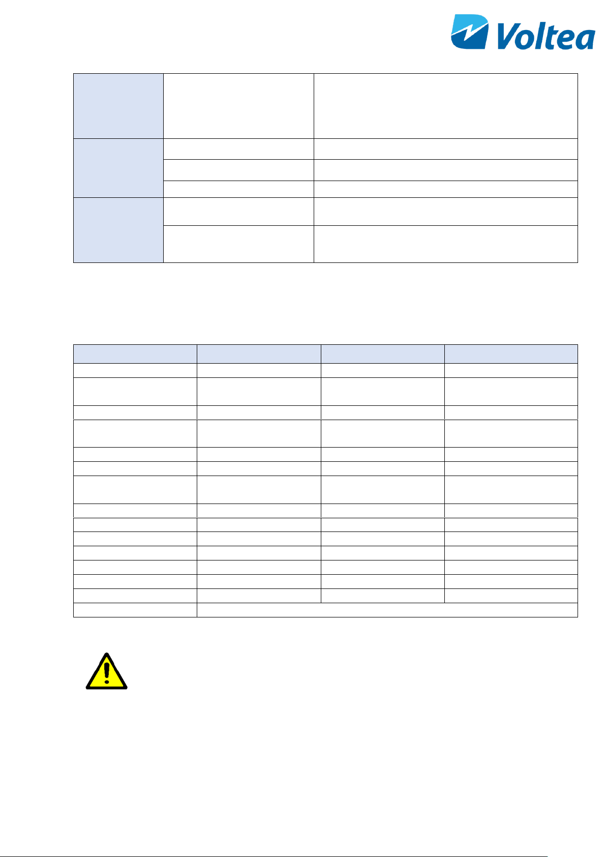
8
In/Outputs
Start/Stop
Pressure switch (standard) or external signal (24 V DC)
Cleaning
Procedure
Automated cleaning with citric acid
Control (auto/manual)
Automatic: on cycles of operation
Storage
1L chemical container
Controls
Remote control / Data
monitoring
Total flow, average conductivity, average voltage, (2G
SIM card with data or locally via laptop)
Parameter change
Locally
*Depends on TDS reduction and water recovery
**Weight without module
***Depends on flow target
4.3 FEED WATER QUALITY
Parameter
UNIT
RANGE
INTERMITTENT
Removal limit
Δppm
0 - 1300
Total dissolved solids
(TDS)
ppm
0 - 2000
Total organic carbon
ppm
< 10
Chemical oxygen
demand
ppm
< 20
< 100
Turbidity
NTU
< 4
< 100
Fats, Oils, Greases
ppm
< 0.5
Total suspended solids
(TSS)
ppm
< 4
< 20
Free Chlorine
ppm
< 2
< 25
pH
2 – 10
1 – 12
Iron total
ppm
< 0.5
Total hardness (CaCO3)*
ppm
< 1000
M Alkalinity (CaCO3)
ppm
< 1000
Pre – filtration
µm
5
Temperature
﮿C / ﮿F
1 - 35 / 34 - 95
Chemicals
Contact Voltea
*Limit depends on set TDS reduction and water recovery
CAUTION!
5-micron filter is the minimum required pretreatment
for the feed water.
Page 10
9
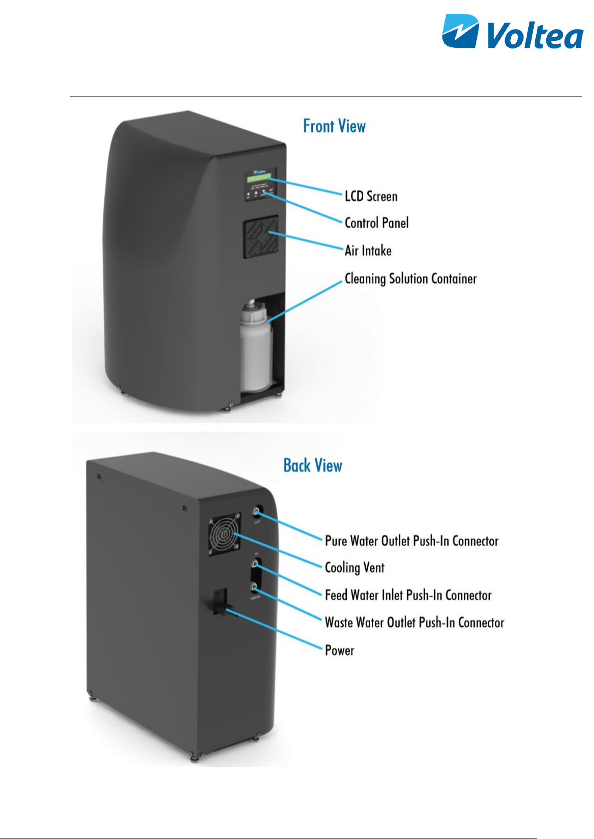
5 SYSTEM OVERVIEW
Page 11
10
6 SYSTEM INSTALLATION
NOTE: Read this section entirely before starting the installation. Follow all applicable plumbing and electrical
instructions.
6.1 PACKING
• The DiUse system is shipped in two boxes.
• One box contains the module and module T-
junction, the other the DiUse frame, power
cable and spare flow restrictors.
Modules weigh 23 kg (50.7 lbs.)
6.2 TOOLS AND MATERIALS
• Safety shoes
• 2x size 13 wrenches
• Hex key number 4
• Flathead screwdriver
6.3 MODULE INSTALLATION
• Loosen the connections holding the curved
cover in place.
• Lift off the curved cover being careful of
protruding parts (e.g. air filter).
Page 12
11
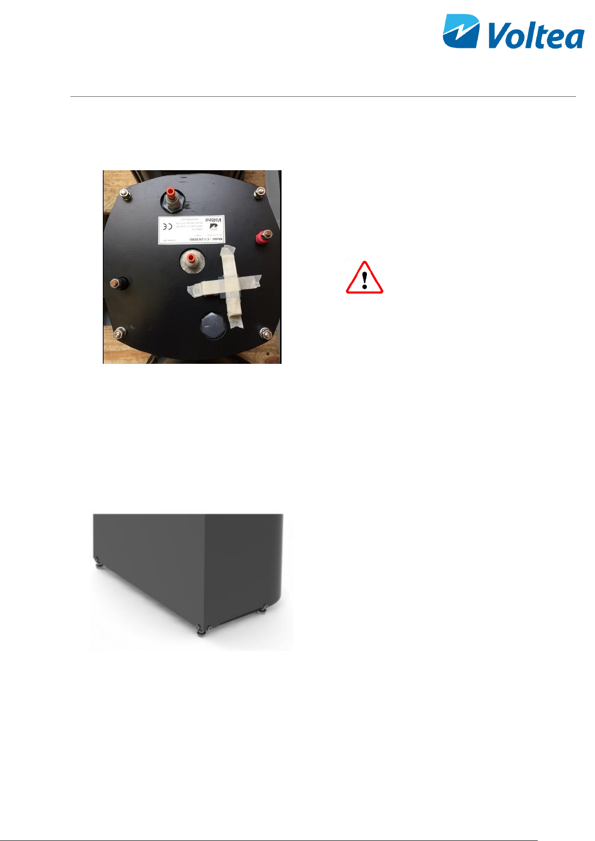
• Remove orange stoppers from module. Add
manifold to center of module using stem
adapter. The module manifold has check valves
pre-installed before each 3/8’’ push in fitting.
• Rotate the module so the red terminal is on the
left and the black terminal is on the right, when
facing the water side of the electrical cabinet.
• Push the module on the frame up against the
stoppers.
Modules weigh 23 kg (50.7 lbs.) and
the system 17 kg (37.5 lbs.). It is recommended to
wear safety shoes during installation.
• If done correctly, the module inlet (the
connection that is NOT in the middle of the
module top) will be facing outward from the
system, and the edge of the module will be in
line with the edge of the frame.
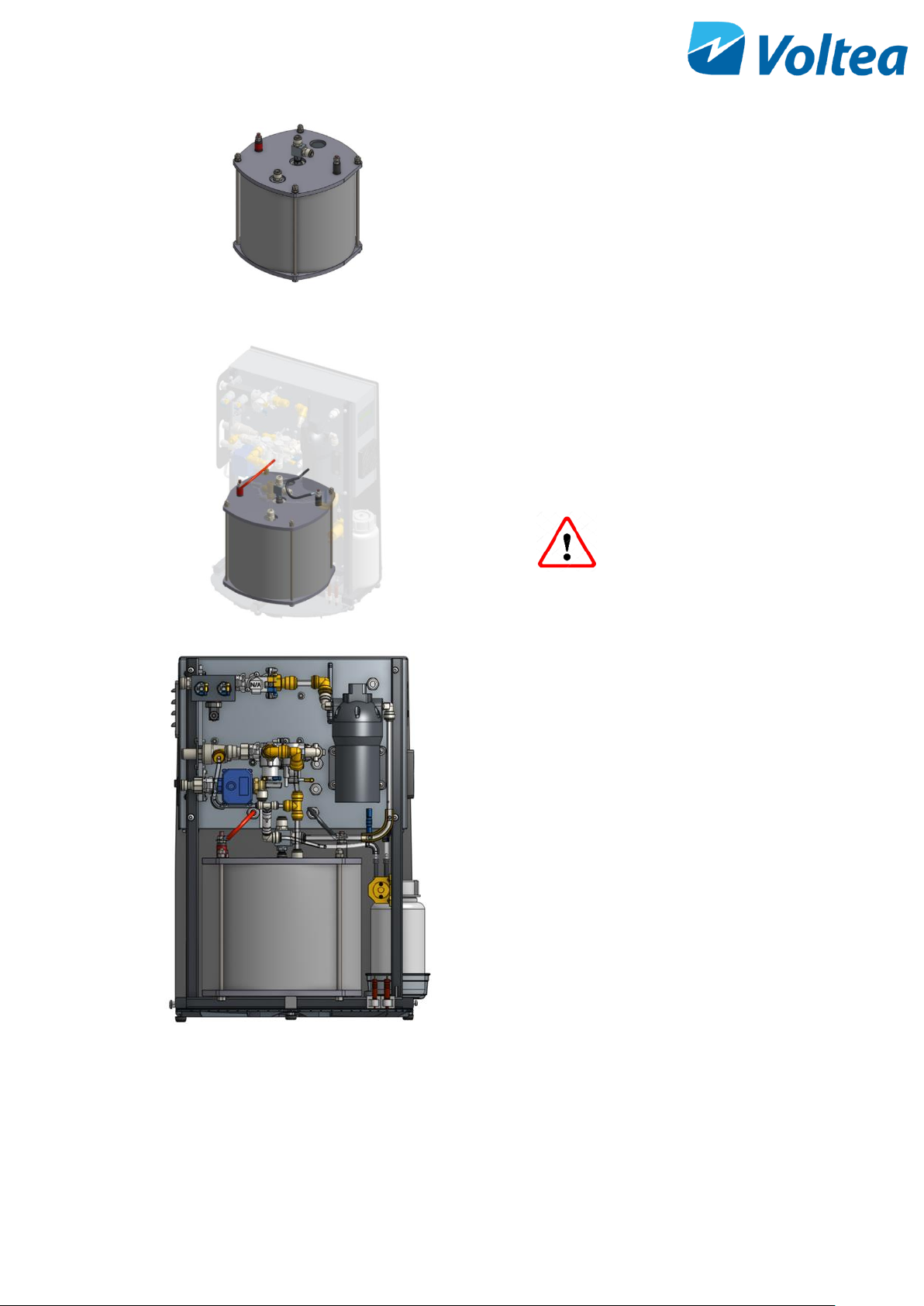
• The vertical tube that is attached to a T-junction
should be pushed into the module outlet. If
placed correctly, pulling on the tube firmly
should not disconnect it from the module.
• The tubing that comes from the waste line
(above the center of the module) should be
pushed into the vertical connection coming
from this point.
Page 13
12
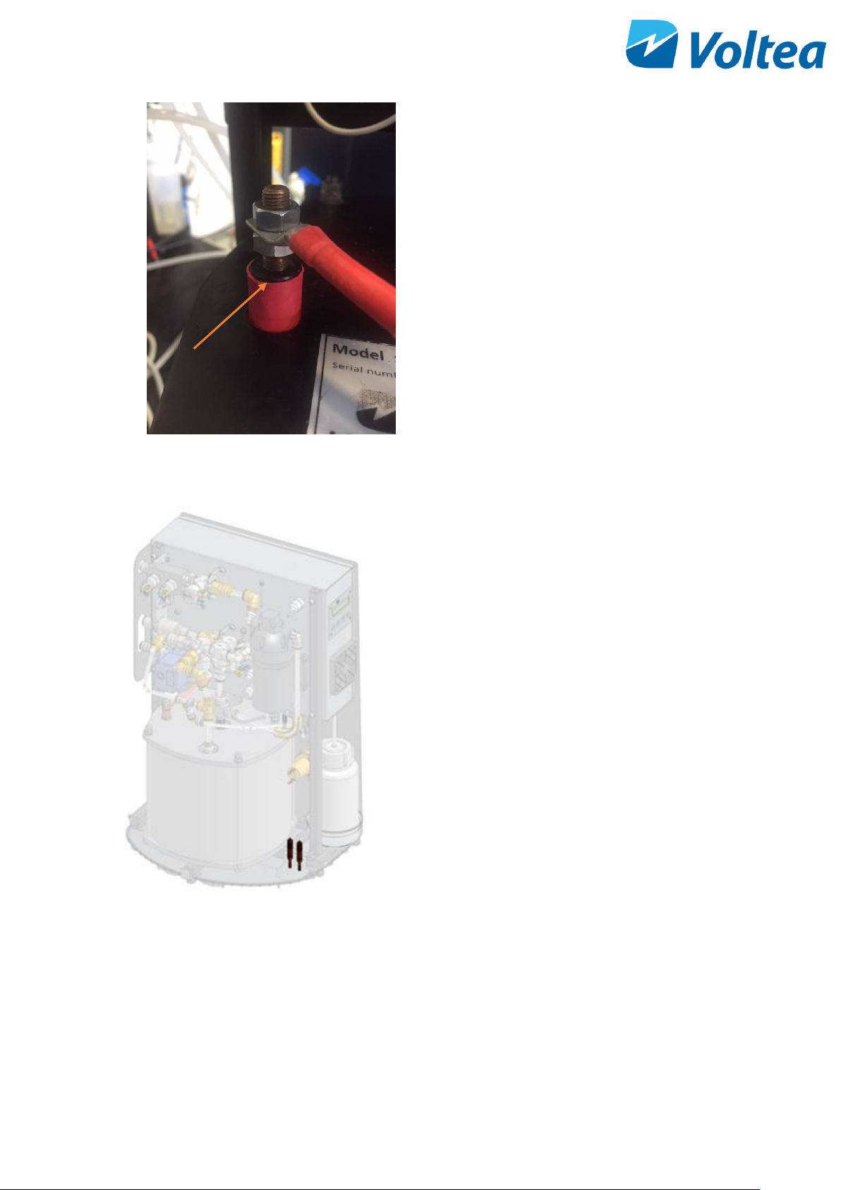
• Each module has one red and one black
electrical terminal, with each terminal having
two M8 nuts. Unscrew one of the nuts from the
red terminal. Place the red cable from the
system on the red electrical terminal, then
screw the nut back on. Tighten using two size 13
wrenches, one on the top nut and one on
bottom nut. Repeat the process with the black
terminal and black cable. Be sure the bottom
nut is isn’t sitting on the plastic bushing.
6.4 PLACING LEAK SENSOR
• Take the two sensors and place them in the
clamps as shown in the image. The tip of the
sensor should be in contact with the leak
tray.
NOTE: Leak tray should always be dry to avoid
triggering the leakage alarm and stopping the
system.
6.5 PLACING THE COVERS.
Place the covers back and tighten the connections holding the covers in place.
NOTE: Every connection has a spacer attached to it. Spacers should be between the covers and frame before
tightening.
Plastic bushing
Page 14
13
6.6 WATER CONNECTIONS
Size 3/8” tubing should be used to connect the inlet to the middle connection on the side of the unit. The purified
(Out) water is discharged through the top 3/8’’ connection. Concentrate (Waste) is discharged through the
bottom 3/8’’ connection. Connections are indicated by stickers.
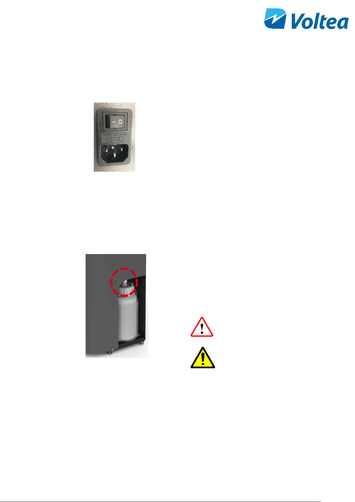
6.7 POWERING THE SYSTEM UP/DOWN
• A power cable is provided with the system.
• Connect the cable to the power connection on
side of unit.
• Turn the switch on to power the system.
NOTE: DiUse systems are specific to either 110 V or 240
V. If in doubt about system specifications, please contact
Voltea.
6.8 REPLACEMENT OF CIP SOLUTION
• Loosen the white tube gland by rotating the
gland nut (topmost piece, circled in red), whilst
holding the bottle steady.
• After the gland nut is loose, unscrew the lid of
the CIP container.
Acid may splash. Avoid
contact with eyes.
CAUTION!
If using citric acid powder
always use distilled or
sterile water for CIP
solution preparation.
Page 15
14
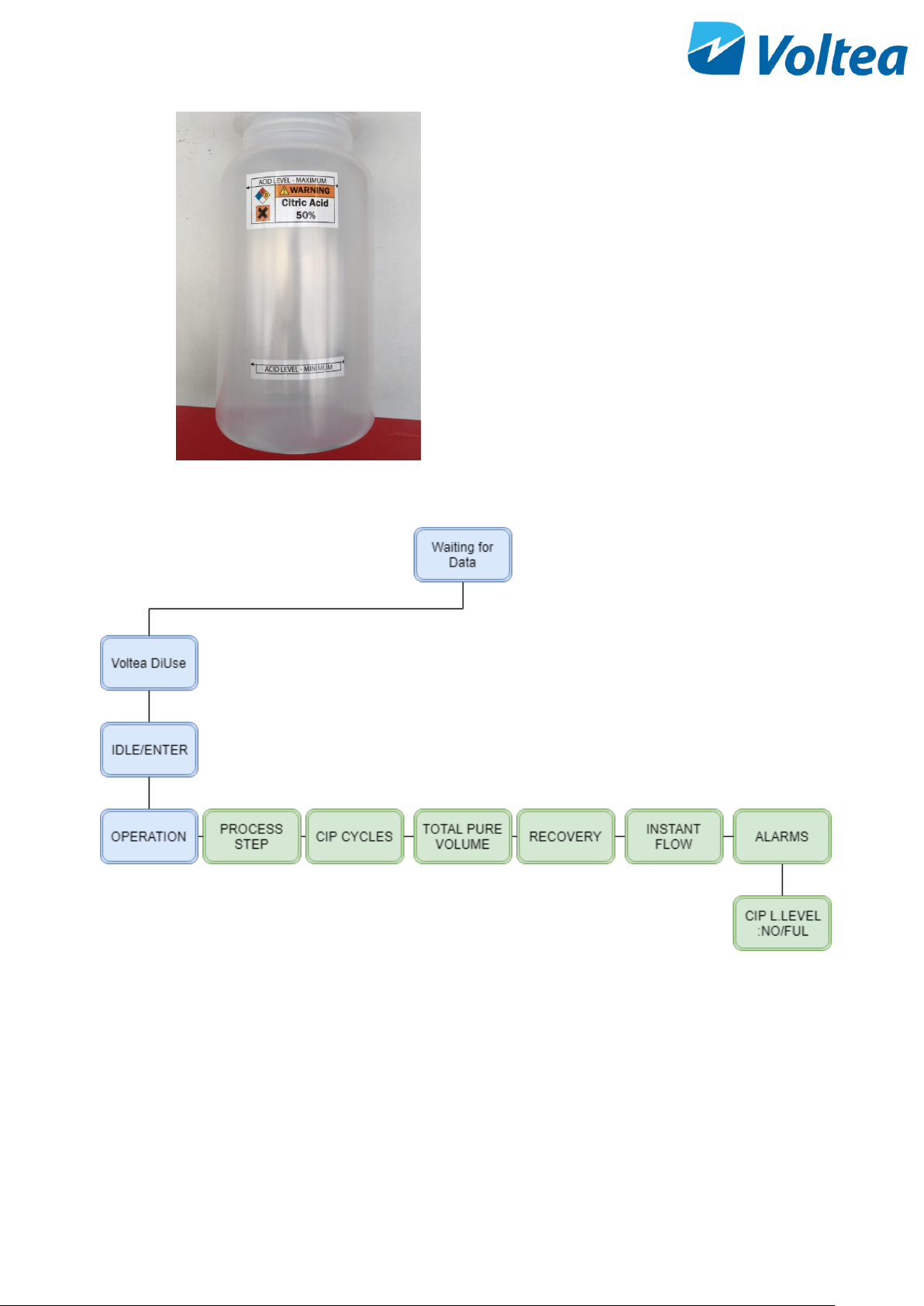
• Fill container with 50% w/w citric acid solution.
The maximum and minimum levels are indicated
by stickers
• Screw the lid of the CIP container back on,
tighten the gland nut until tube is held
• Go to CIP L. LEVEL in alarms and press enter, the
alarm now reads CIP L.LEVEL : FUL
NOTE: CIP solution level is calculated based on the CIP’s pump capacity to exhaust the 1L of CIP solution. For
this reason, it is mandatory to reset the CIP alarm once the CIP bottle is refilled. Around 36 ml of CIP solution is
used per CIP event.
6.9 FLUSHING THE MODULE
Before normal operation the modules should be flushed for at least 15-20 minutes. For instructions on module
flush please refer to section 12.1.
Page 16
15
7 SYSTEM START UP - OPERATION
Power the system up. Using the buttons on the LCD screen, press Enter to go from Voltea DiUse to IDLE-START.
Press Enter again to start operation.
NOTE: To change target output conductivity please refer to chapter 8.4.1
NOTE: If the system is not reaching target pure conductivity, a flow restrictor change may be necessary. Voltea
or a trained reseller can assist with choosing the best option for the specific conditions.
7.1 OPERATION WITH PRESSURIZED TANK
• Once the pressure on the outline after the system drops below 2 bar (29 psi), the system will
automatically start producing water.
• When the pressure on the outline increases above 3.5 bar (51 psi), the system will immediately stop
producing water and it will perform a flush/shunt step for 40 seconds before entering wait mode.
NOTE: Active starting signal for more than 20 minutes will result in a bypass alarm. Bypass alarm is resolved
automatically when the starting signal is not active.
7.2 OPERATION WITH ATMOSPHERIC TANK
Operating DiUse with a 24 V DC potential free dry contract will require custom modifications.
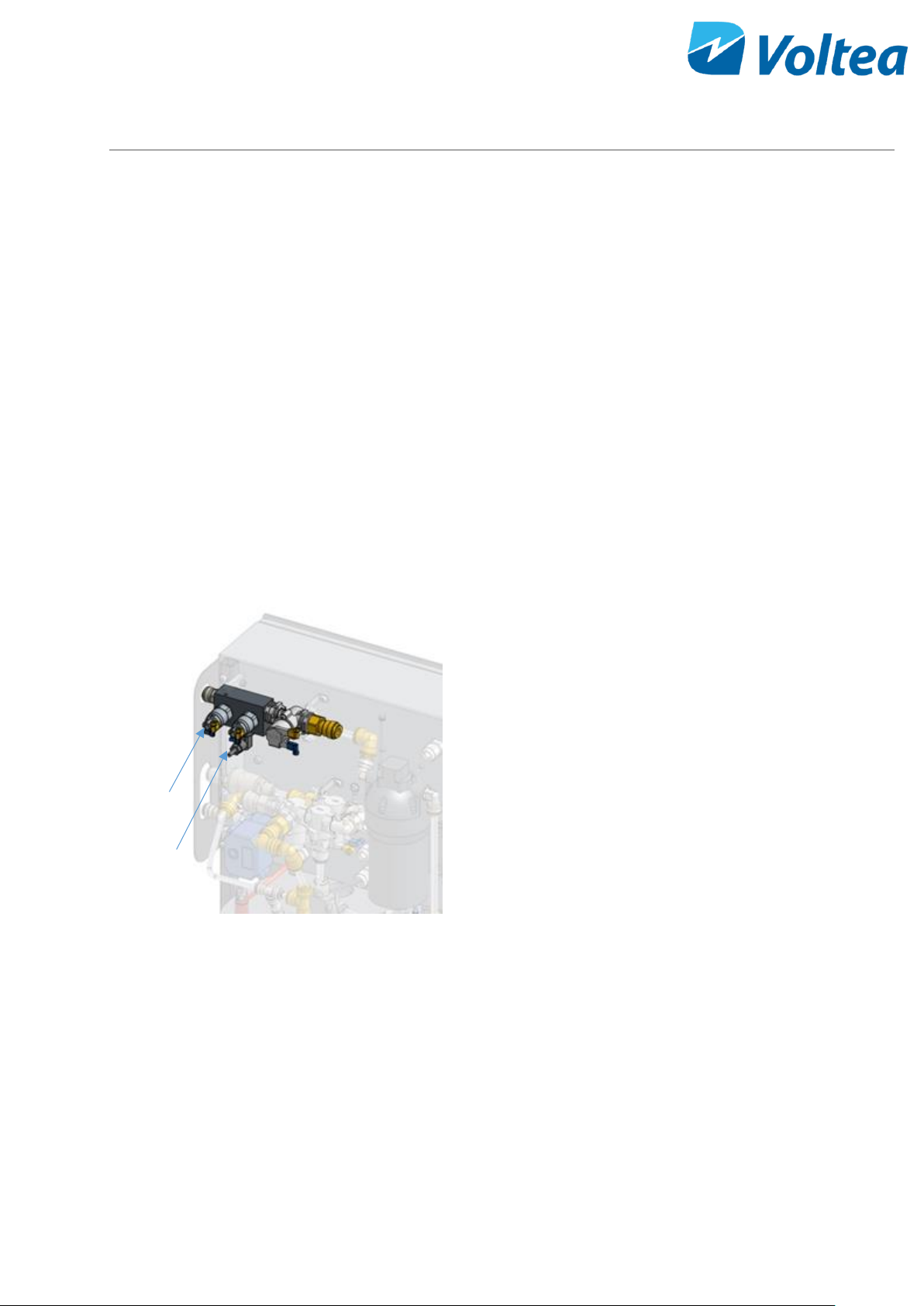
• The system can be controlled by any 24 V DC
potential free dry contact such as a level sensor.
• To control the start signal with a level sensor,
disconnect the electrical cables connected to
pressure switch “P2”
• Connect these cables to a level sensor or other
selected switch.
• To control the stop signal with a level sensor,
disconnect the electrical cables connected to
pressure switch “P1”
• Connect these cables to a level sensor or other
selected switch.
P1
P2
Page 17
16
7.3 SYSTEM PUMP
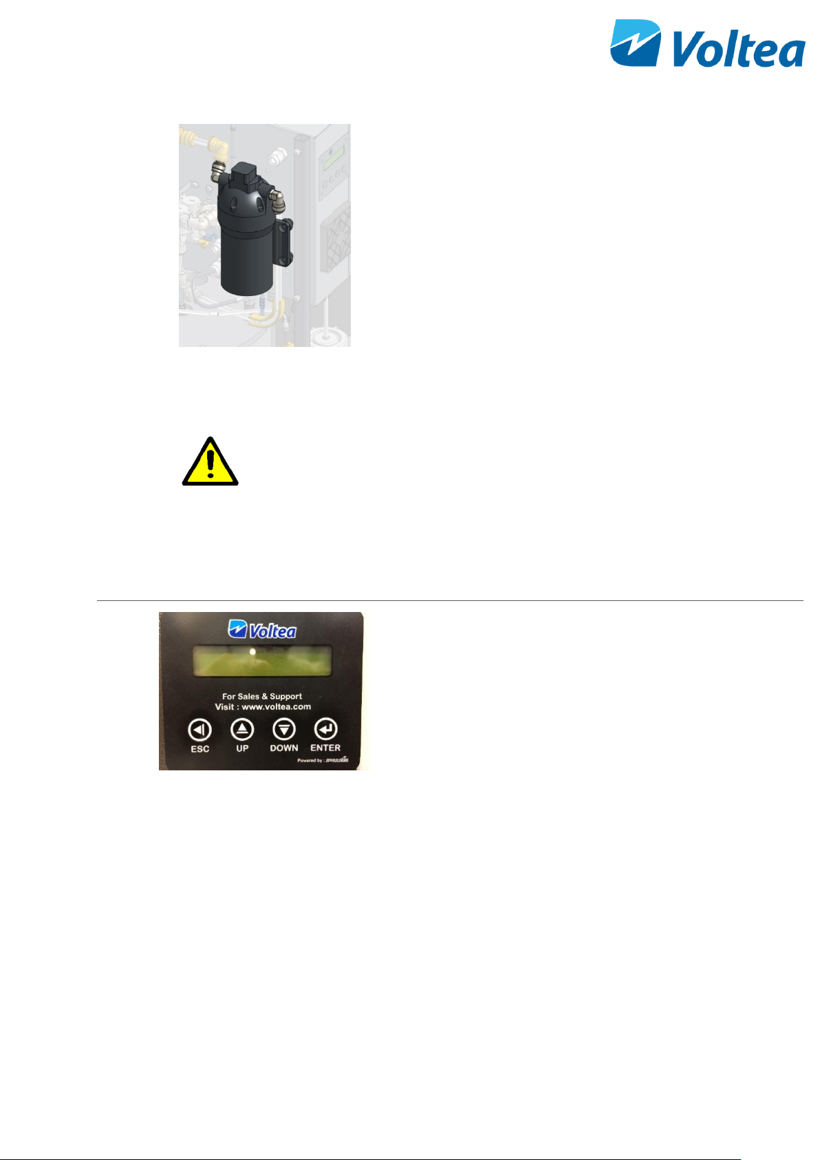
• DiUse is equipped with a system pump to
maintain the operational flow.
NOTE: Target flow is a setpoint and should only be
changed after consulting Voltea.
• The pump operates during pure step and is Idle
during prepure, waste and HF waste steps.
• Depended on the inlet water pressure and the
pressure drop through the module the pump
adjusts.
NOTE: If the inlet flow is enough for CapDI optimal
operation, pump will not start. Pump will start only if
pressure compensation is needed.
CAUTION!
Operating DiUse with an inlet pressure lower than 3 bar
may result in extensive pump operation and potentially
pump failure.
8 SYSTEM CONTROL THROUGH LCD
The system can be controlled using the LCD screen and
the keypad. Navigate through the screens using the UP
and DOWN buttons, confirm selection with ENTER, and
return to the previous screen by pressing ESC.
NOTE: If the screen is black and not responding please
contact Voltea.
Page 18
17
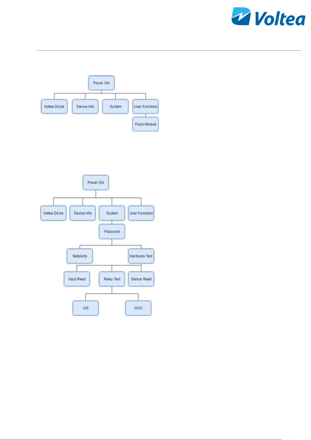
8.1 DIUSE SCREEN NAVIGATION CHART
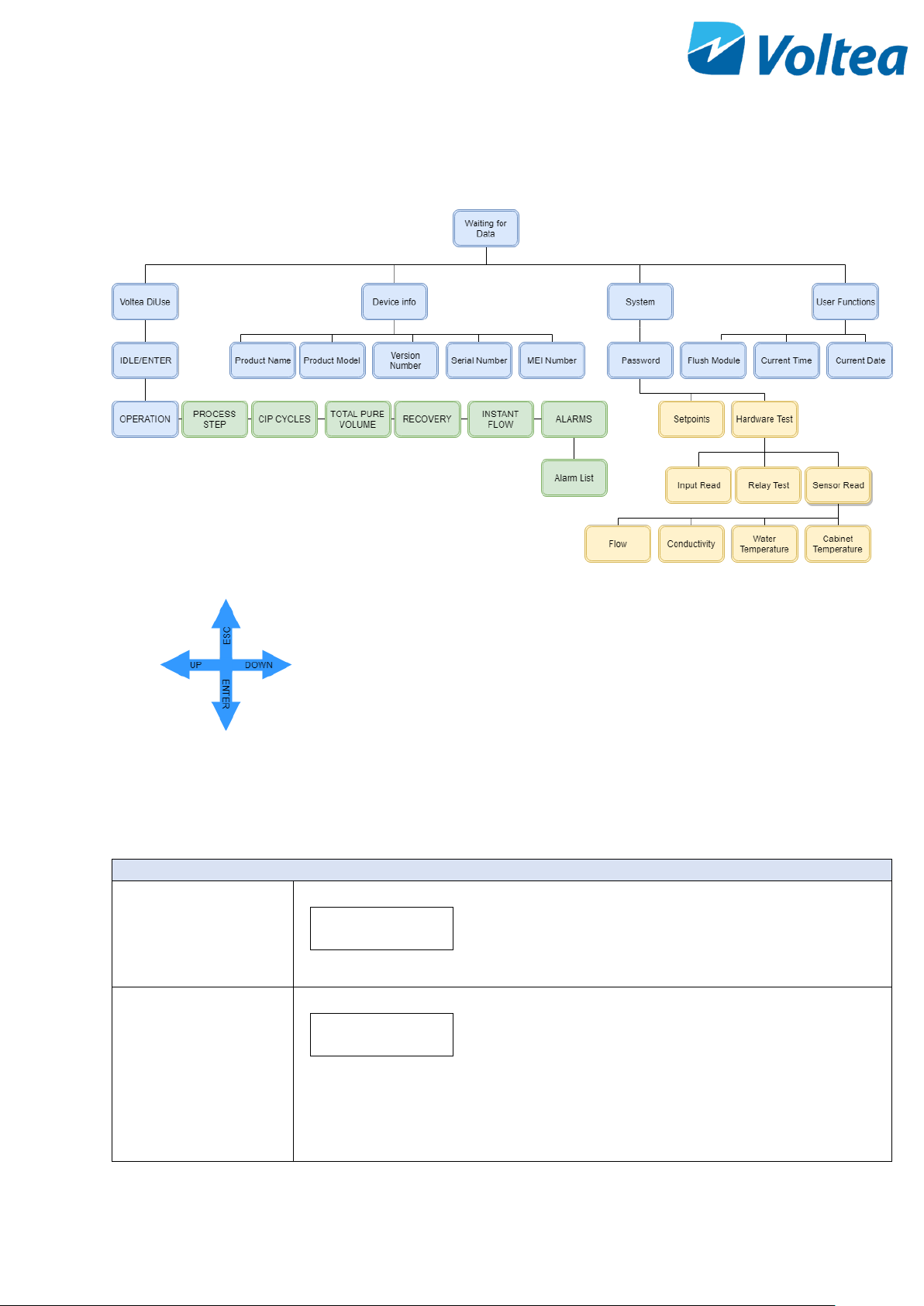
The flow chart gives an overview of the DiUse functions and parameters that can be controlled through the LCD.
NOTE: The password is available to authorized dealers.
8.2 VOLTEA DIUSE
Voltea DiUse branch
IDLE/ENTER
IDLE/Enter
100 uS/cm
• This is the initial screen appearing after
powering up. System is in IDLE, activate the
system by pressing enter.
• Average conductivity of the last cycle is also
presented.
OPERATION/CLEANING
OPERATION
100 uS/cm
• The system is operating and cycling through
the process steps.
• Average conductivity of the last cycle is also
presented.
Page 19
18
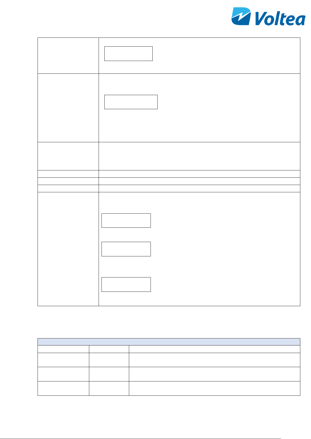
CLEANING
100 uS/cm
• The system is performing a cleaning in place
(CIP).
• Average conductivity of the last cycle is also
presented.
PROCESS/CIP step
PROCESS/CIP STEP
110/110
• In this screen you can see the process or CIP
step currently active.
• For a detailed explanation of all the process
steps please refer to chapter 8.2.1
• The numbers below the process/CIP step
represents the total time of the step and the time
remaining in seconds.
CIP CYCLES
Cycle count displays the complete cycles remaining until the next CIP. A CIP occurs
by default after 432 cycles. After a complete cycle (Pure - Waste - HF Waste Prepure) the Cycle counter is reduced by 1. When the Cycle counter reads Cycle:
0/432 a CIP step will follow.
TOTAL PURE VOLUME
The total pure volume produced in litres since the start of operation.
RECOVERY
Recovery rate of the system.
INSTANT FLOW
Current flow in L/min.
ALARM
All the alarms are presented in 3 forms:
If the alarm never occurred.
Alarm type: NO
1/1/1 0:0
If the alarm is currently active.
Alarm type: YES
yy/mm/dd/ time
To acknowledge the alarm press, Enter.
If the alarm occurred in the past and it is already removed/resolved.
Alarm type: NO
yy/mm/dd/ time
For a more detailed explanation of all the alarms please refer to chapter 8.2.2
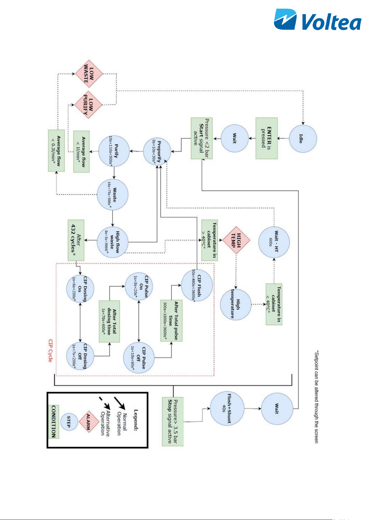
8.2.1 Process steps
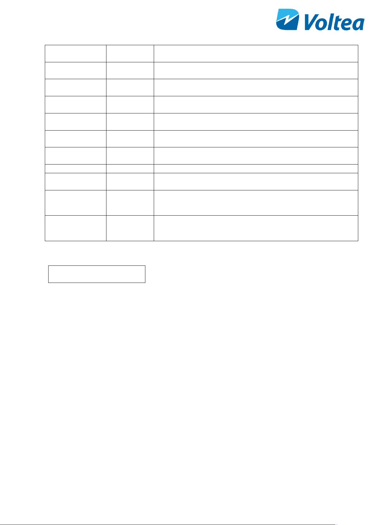
PROCESS STEPS
STEP Name
LCD Name
Description
Idle
IDLE
System powered but not operating. Press Enter to start system
operation.
Prepurify
PREPURIFY
Pre-purify phase of cycle. Flushes any remaining waste water from the
module.
Purify
PURIFY
CapDI applying power to the module to remove salt and lower
conductivity.
Page 20
19
Waste
WASTE
Module regenerating. High conductivity, concentrated water is being
sent to drain.
High Flow Waste
HIGH FLOW
WASTE
High flow waste. Part of the waste step that has a high flow to help
clear out the module.
Wait
WAIT
Waiting to start operation, when the pressure switch is engaged due
to pressure being higher than 2 bar / 29 psi.
CIP Dosing On
CIP DOSING
ON
CIP Pump runs, waste valve is open to release system pressure.
CIP Dosing Off
CIP DOSING
OFF
CIP pump turns off, small amount of water pushed in to push acid into
the module.
CIP Pulse On
CIP PULSE ON
CIP solution flows through the module and is discharged through the
waste line.
CIP Pulse Off
CIP PULSE OFF
No flow. Pulse is on and off to increase the residence time of the acid
in the module cells.
CIP Flush
CIP FLUSH
System flushing water through the CapDI module.
High Temp
HITP
High temperature, operation is paused until the air temperature
drops below the setpoint.
Wait High
Temperature
W-HT
Wait until high temperature is lowered. System does a recheck every
600 seconds. When the air temperature is lowered the system
automatically restarts.
Flush and Shunt
FLUSH+SHUNT
Flushes the module for 40 seconds while setting the module to 0
Volts.
NOTE: Flush – Shunt duration cannot be modified in setpoints.
8.2.2 Alarms
OPERATION
100uS/cm!
If an alarm occurs a “!” will appear in the process step screen. Important
alarms can result in DiUse shut down.
Alarms screen will show a binary representation of which alarms are
active. Pressing Enter will take you to the Alarms list. In the alarms list,
it is possible to scroll through alarms and see the date and time at which
they last occurred, with any active alarms indicated by a “Yes”.
Alarms are separated in three categories :
• Alarms that do not stop operation such as the CIP low level alarm
and do not resolve automatically. When alarms of this type are
triggered they can be acknowledged by navigating to the alarms
screen and pressing enter.
• Alarms that do not stop operation and automatically resolve
when their triggering condition is no longer active, such as the
bypass alarm.
• Alarms that force the unit to jump to Idle. These alarms
automatically reset when you press Enter while In the Idle
screen and the unit resumes operation if the triggering condition
is no longer active, for example the leakage alarm.
Page 21
20
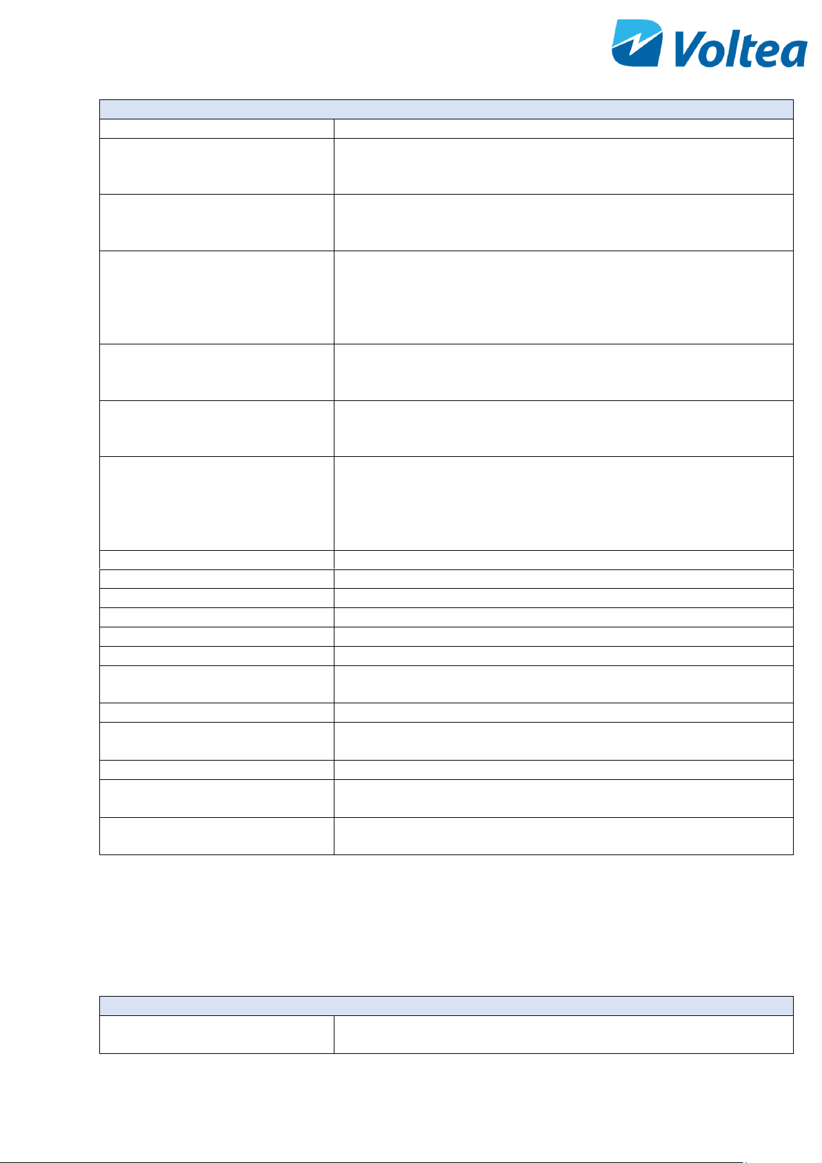
ALARMS
Name on screen
Description
LOW PURIFY
Low flow during the Purify phase. Set in the Set Points screen. Only
triggered at the end of the Purify phase. Unit jumps to Idle, press Enter
to resume operation.
LOW WASTE
Low flow during the Waste phase. Set in the Set Points screen. Only
triggered at the end of the Waste phase. Unit jumps to Idle, press Enter
to resume operation.
BYPASS ALARM
Pure line pressure has dropped below the set point of the bypass
pressure switch (standard is 2 bar / 29 PSI) for more than 20 minutes.
Alarm automatically resolves when pressure increases above 2 bar/ 29
psi. Voltea recommends opening a bypass or reviewing operational
parameters with Voltea staff.
CAB. TEMP
System goes to wait due to high temperature within the electrical
cabinet. Set in setpoints. Unit jumps to wait until it cools down then
resumes normal operation.
LEAKAGE
If the two leakage sensors come into contact with water, this alarm will
be triggered, and the system will go into Idle. Dry the area and press
Enter to resume operation.
CIP L. LEVEL
CIP solution tank is almost empty.
NOTE: CIP solution level is calculated based on the CIP’s pump capacity
to exhaust the 1L of CIP solution. When this alarm is triggered refill the
CIP tank and acknowledge the alarm via the alarm screen. The counter
resets.
PAE COMM ERR
PCB and power supply not communicating - Resolves automatically.
PAE OVP SHUT
Over voltage protection - Resolves automatically.
PAE OLP SHUT
Overload protection - Resolves automatically.
PAE FAN FAIL
Power supply fan failure - Resolves automatically.
PAE SMPS ERR.
Switch mode power supply – Resolves automatically.
PAE OTP SHUT
Module power supply error, over potential – Resolves automatically.
PAE HIGH TEMP
Module power supply error, too high temperature – Resolves
automatically.
PAE ACP DOWN
Power supply interrupted – Resolves automatically.
PAE AC IP FZ
Module power supply error cut off mains power – Resolves
automatically.
I2C
EC probe communication interrupted – Resolves automatically.
ZERO EC
Conductivity reading is 0 for more than 5 seconds, unit jumps to Idle –
Press Enter to resume operation.
TEMP.ERR
Water temperature reading out of range. Unit uses the last known
temperature – Resolves automatically.
8.3 DEVICE INFO
In this section the product name, product model, firmware version, serial and IMEI number are available.
8.4 SYSTEM
System branch
Password
To access system, you will be asked for a password. The default
password is 1010.
Page 22
21
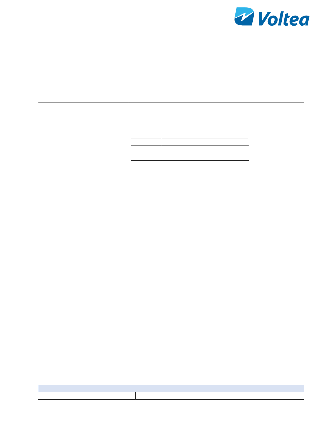
Setpoints
When advised by Voltea, setpoints can be adjusted via the LCD.
A cursor can be seen that shows which digit is being edited. UP
increases the value, and DOWN decreases it. Press ENTER to move onto
the next digit. The edit will only be saved when ENTER is pressed on
the final digit.
For a more detailed explanation of all the setpoints please refer to
chapter 8.4.1.
Hardware test
From Hardware Test the Input Read, Relay test and Sensor Test are
accessible.
Input read:
1
Unassigned
2
Bypass
3
Leak sensors
4
Start signal
Input variables can have 2 values, Lo and Hi. Hi when the signal is
received and Lo when there is no signal. E.g.:
• When the bypass is not active and no leakage while starting
signal is active it should read 1Lo 2Lo 3Lo 4Hi
• When the bypass is connected it should read 1Lo 2Hi 3Lo 4Hi
• When there is a leakage it should read 1Lo 2Lo 3Hi 4Hi
Relay test: Gives access to manual operation for the valves, CIP pump
and relays.
• MIV: Main inlet valve
• HFIV: High flow valve
• POV: Pure outlet valve
• WOV: Waste outlet valve
• CIP: CIP pump
• PVR: Shunt relay
• NVR: Polarity changing relay
• PUMP: Power supply
Sensor read: Gives access to Flow, Conductivity, Water Temperature
and Cabinet temperature live measurements.
8.4.1 Setpoints
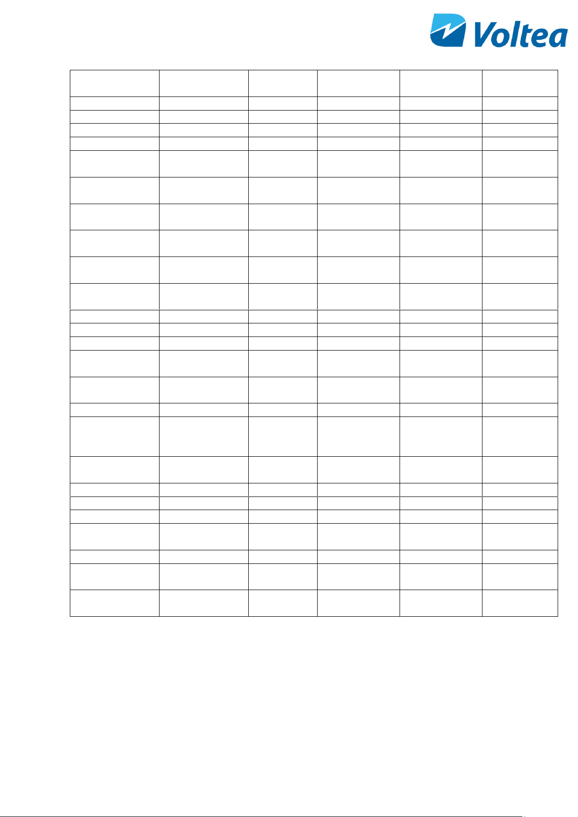
Setpoints have a minimum and a maximum value. Once a setpoint is selected the current setpoint value will be
displayed amongst minimum and maximum values.
A cursor can be seen that shows which digit is being edited. UP increases the value, and DOWN decreases it.
Press ENTER to move onto the next digit. The edit will only be saved when ENTER is pressed on the final digit.
Setpoints
LCD Label
Parameter
Min Value
Max Value
Default Value
Unit
Page 23
22
Pure EC Target
Outlet
Conductivity
0
2000
100
µS/cm
PrePurify Time
Pre-Purify Time
0
30
10
s
Purify Time
Purify Time
10
500
110
s
Waste Time
Waste Time
10
500
75
s
HF Waste Time
HF Waste Time
0
500 5 s
CIP Step 1A
CIP Dosing On
Time
1
200 4 s
CIP Step 1B
CIP Dosing Off
Time
1
200 9 s
CIP Step 1
CIP Dosing Total
Time
1
600
117
s
CIP Step 2
CIP Flow Pulse
Total Time
300
7200
1800
s
CIP Step 2A
CIP Flow Pulse On
Time
1
20 6 s
CIP Step 2B
CIP Flow Pulse Off
Time
1
60
20
s
CIP Flush Time
CIP Flush Time
50
3600
180
s
Wait HT Time
Wait HT Time
30
3600
600
s
P. Flow Target
Flow
0.0
10.0
2.6
L/min
Low Flow P.
Alarm
Low Flow Purify
Alarm
0.0
10.0
1.0
L/min
Low Flow W.
Alarm
Low Flow Waste
Alarm
0.0
10.0
0.3
L/min
CIP Cycles
CIP Cycles
5
5000
432
Temp Alarm
Temperature
Alarm High
Setpoint
20
60
40
﮿C
Max CIP P.R.T
Max CIP Pump
Runtime
5
2500
1000
S
Pump P-factor
Pump P-factor
0.25 2 0.4
Dyna P-factor
Dynamic P-factor
0.0
9.99
0.05
P. Max Volt
Pure Max Voltage
0.0
2.0
1.4
V
W. Max Volt
Waste Max
Voltage
0.0
2.0
1.4
V
w_value
W value
0.5
2.0
1.05
Flow k factor
Flowmeter K-
factor
10
2000
720
Clear
Total Volume
- - - -
NOTE: Clear total volume is not a setpoint but a system function that resets the total volume of pure water
produced by DiUse since beginning of operation. For protection, it is located in set points that are password
protected.
Page 24
23
8.5 USER FUNCTIONS
User Functions branch
Flush Module
Starts module flush with feed water.
Current Time
Displays system time in UTC (Coordinated Universal Time)
A cursor can be seen that shows which digit is being edited. UP increases the value,
and DOWN decreases it. Press ENTER to move onto the next digit. The edit will only
be saved when ENTER is pressed on the final digit.
NOTE: If a SIM card is active, system will automatically synchronize with the network
time. For more details on GSM communication refer to chapter 9.1.
Current Date
Displays system date.
A cursor can be seen that shows which digit is being edited. UP increases the value,
and DOWN decreases it. Press ENTER to move onto the next digit. The edit will only
be saved when ENTER is pressed on the final digit.
NOTE: If a SIM card is active, system will automatically synchronize with the network
date. For more details on GSM communication refer to chapter 9.1.
9 ADVANCE SYSTEM FUNCTIONS
9.1 RECEIVE DATA AND ALARMS REMOTELY
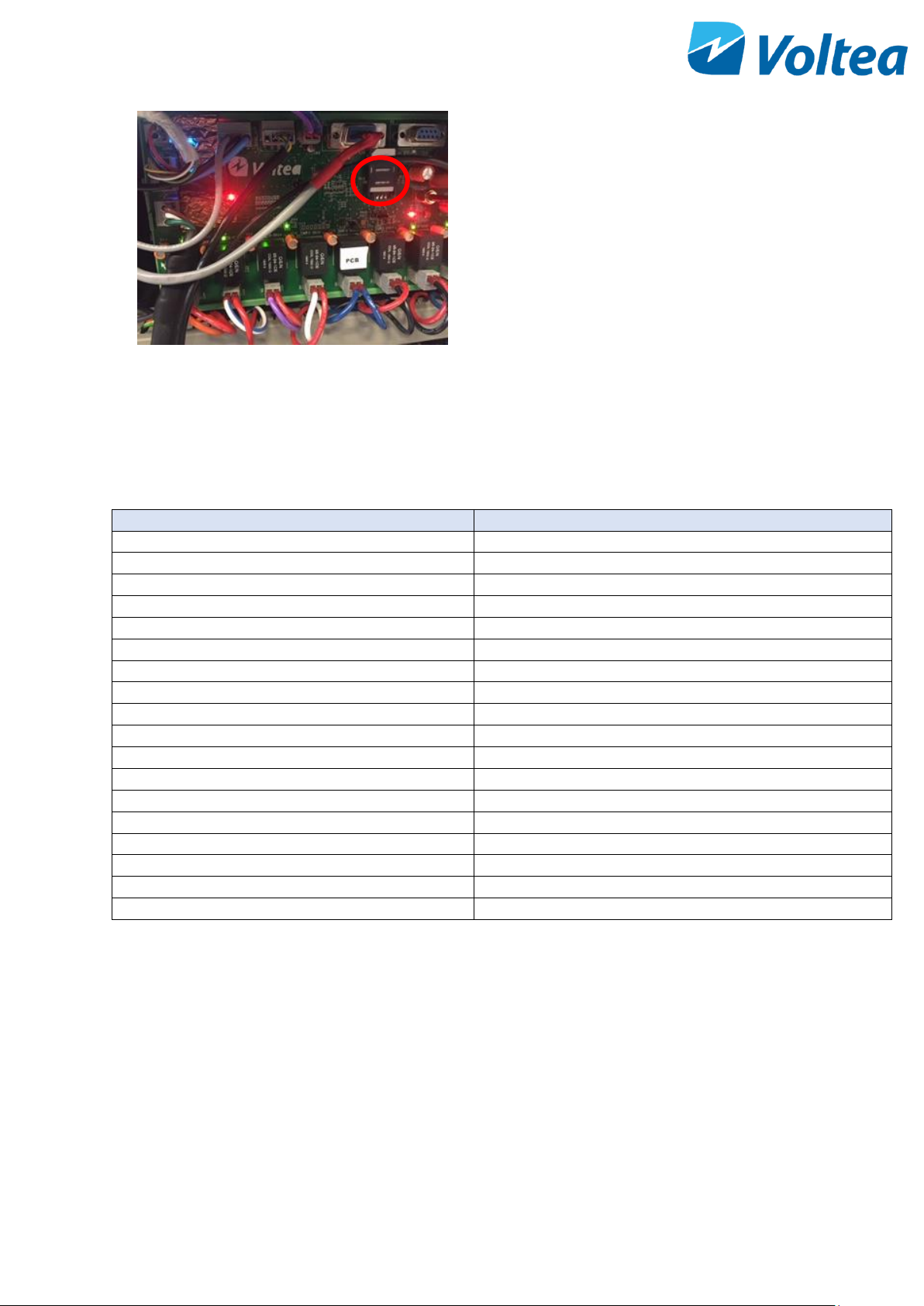
• The system comes with a GSM communication
antenna. To utilize this feature, insert a dataready, unlocked SIM card into the SIM slot.
System needs 2G coverage to communicate.
Page 25
24
• Once the SIM is placed, use a Laptop and the
Docklight software provided by Voltea to put in
the email address and phone number of the
data/alarm recipient to receive information. For
more information refer to chapter 9.2.4.
NOTE: Nano and micro SIM cards are not compatible
with the card reader.
• If an alarm is active the system will automatically
send an SMS to every number in the list. The
SMS contains only the alarm code.
NOTE: Soft alarms will not trigger an SMS, these soft
alarms are PAE alarms, TEMP. ERR and I2C alarm.
Alarm code
Alarm explanation
1h
LOW PURIFY
2h
LOW WASTE
4h
BYPASS ALARM
8h
CAB. TEMP
10h
LEAKAGE
40h
CIP L.LEVEL
80h
PAE COMM
100h
PAE OVP SHUT
200h
PAE OLP SHUT
400h
PAE OTP SHUT
800h
PAE FAN FAIL
1000h
PAE SMPS fail
2000h
PAE HIGH TEMP
4000h
PAE ACP DOWN
8000h
PAE AC IP FZ
20000h
I2C
40000h
ZERO EC
80000h
TEMP.ERR
NOTE: These alarms can also occur in combinations. If the code is a combination of more alarms, please use
the excel file provided by Voltea to identify the corresponding alarms.
9.2 CONNECTING TO LAPTOP AND UTILIZING DOCKLIGHT
9.2.1 Laptop connection
Before connecting the laptop, power on the unit.
Page 26
25
NOTE: These functions are generally not needed for the setup but are required for adding email and SMS
monitoring functionality.
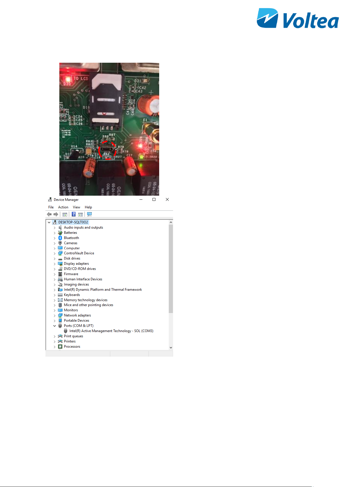
• Connect the laptop to the system using a USB 2.0
cable (micro-USB to USB) placed directly into the
micro-USB port of the PCB.
• Open device manager and click the PORTS tab.
Check the virtual port assigned to the connected
USB.
NOTE: To connect to laptop, request Voltea’s Command
program (Docklight).
Page 27
26
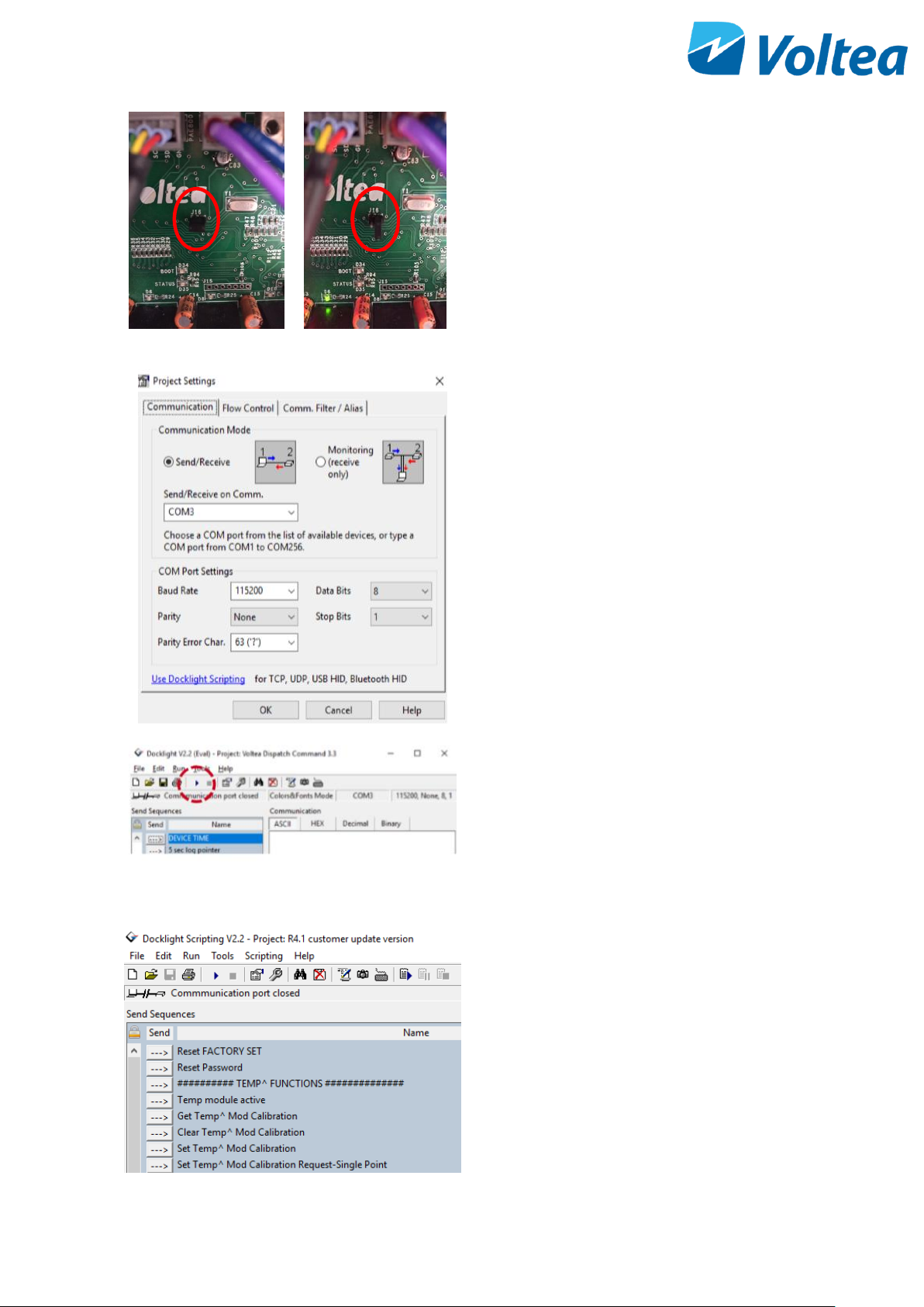
NOTE: The jumper on the PCB should be in the open
position before connecting to the laptop. Open position is
default for the jumper, check only when unable to
connect.
• Open Docklight software.
• Go to Tools →Project setting
• In the Send/Receive on Comm. field select the
virtual port assigned to your USB. Press OK.
• Press the Start button to begin communication. If
errors occur after multiple attempts, unplug the
USB from the laptop and plug it in again.
9.2.2 Docklight
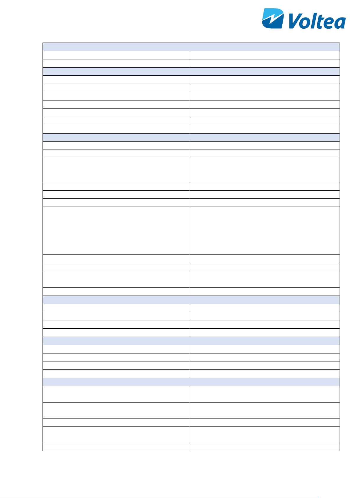
• With Docklight you can calibrate the conductivity
probe, set emails and phone numbers for alarms
and others. To execute the command click the
arrow, located to the left of each command.
Closed
Open
Page 28
27
COMMANDS
Reset FACTORY SET
Reset to factory settings
Reset Password
Reset password
TEMP^ FUNCTIONS
Temp module active
Activates the temperature module
Get Temp^ Mod Calibration
Last calibration is checked
Clear Temp^ Mod Calibration
Clears previous calibration
Set Temp^ Mod Calibration
Adjust the calibration temperature
Set Temp^ Mod Calibration Request – Single point
Temperature single point calibration
Get Temp^ Mod Calibration Confirmation
Calibration confirmation
Read Temp^ Mod Current Temperature
Displays current temperature probe reading
CONDUCT^ FUNCTIONS
Set conductivity Probe Active
Activates the EC probe
Get Conduct^ Probe Type (divide the result by 100)
Displays the EC probe type.
Set Conduct^ Probe Type (multiply actual by 100)
Sets the EC probe type
NOTE: The EC probe type is set by Voltea and its not
advised to change.
Clear Conduct^ Mod Calibration Request
Clears calibration request
Set Conduct^ Mod Calibration Reg
Dry calibration point
Set Conduct^ Mod Calibration Request-Dry
Dry calibration confirmation
Set Conduct^ Mod Calibration Reg 2
Single point calibration.
NOTE: Voltea suggests a 147µS/cm solution for
calibration. Docklight has this solution as a preset. If
you want to use a different solution double click on Set
Conduct^ Mod Calibration Reg 2 and change the
conductivity value.
Set Conduct^ Calibration Request – Single Point
Single point calibration confirmation
Get Conduct^ Mod Calibration Confirmation
Calibration confirmation
Get Conduct^ Mod Conductivity (For actual value
divide by 100)
Displays current conductivity reading, for the actual
value divide the received value by 100.
Set Conductivity Probe to Hibernate
Deactivated EC probe
FLOW^ FUNCTIONS
Get Flowmeter Single Reading
Displays current flow
Clear Flowmeter K value
Clears flowmeter K value
Get Flowmeter K value
Displays K value
CLEAR Flowmeter Reading
Clear flowmeter reading
Serial Number FUNCTIONS
Get Serial Info
Displays DiUse serial number
Get FM unique id
Displays system’s unique ID
Set Serial Number
Change Serial Number
Get Serial Number
Display Serial Number
GSM FUNCTIONS
Set Admin Mobile No
Set administrator mobile number to receive alarms and
data.
Set User 1 Mobile No
Set user 1 mobile number to receive alarms and data
NOTE: UP to 10 users possible
Set Admin Email ID
Set administrator email to receive alarms and data
Set User 1 Email ID
Set user 1 email to receive alarms and data
NOTE: UP to 10 users possible
Email Setting – USERNAME
Internal server username
Page 29
28
Email Setting – PASSWORD
Internal server password
Email Setting – SENDER ADDRESS
Sender address
Email- Setting – OUTGOING MAIL SERVER ADDRESS
Mail server address
Email Setting – OUTGOING MAIL SERVER PORT
NUMBER
Outgoing mail port number
Set APN Settings
Access Point Name settings for GSM communication
GENERAL SETTINGS
Get System Time zone
Displays time zone
Write System Time zone
Sets system time zone
Mobile debug ON
Debug sequence enabled
Mobile debug OFF
Debug sequence disabled
Mobile Strength
GSM signal strength appears on screen, a value above
10 is considered sufficient.
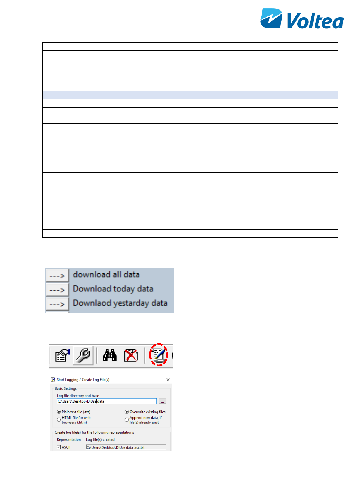
Download all data
Downloads all operational data in a txt. form
Download today’s data
Downloads today’s operational data in a txt. format
Download yesterday’s data
Downloads yesterday’s operational data in txt. format
Email daily report
Triggers the daily report via e-mail
Date wise report displays
Displays on Docklight screen the daily summary report
Low view enable
All operational events, measurements and calculations
appear on Docklight screen. 5 seconds log.
Log view disable
Disables the on screen event log.
Reset Controller
Internal PCB reset
Get Firmware Version
Displays firmware version
Change Password
Changes the password
9.2.3 Downloading operational data from the system
Operational data can be downloaded from the system
utilizing Docklight, to connect your laptop to the system
via Docklight please refer to chapter 9.2.1. Laptop
Connection.
To download use one of three commands depending on
the timeframe you are interested in, for more information
on these 3 commands refer to chapter 9.2.2.
Before downloading select the folder where you want to
save the data:
• Click the Start Communication Logging, button
can be found on the ribbon.
• Select the directory to save the txt. file.
NOTE: If the file name is not changed, the file will be
overwritten.
• Click on one of the three commands to download
the data.
Page 30
29
9.2.4 Adding e-mail and telephone users.
• It is possible to input email addresses and phone
numbers into a list that can be used to receive
data in the form of daily reports (chapter 9.2.5)
and alarms from the system. This list can hold up
to 10 addresses and 10 mobile phone numbers.
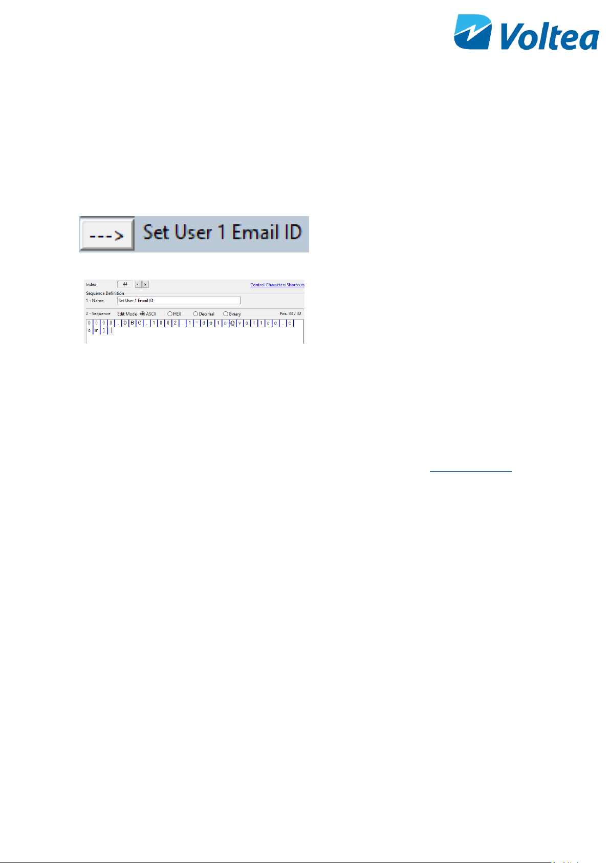
• Using Docklight program, double click on the Set
User email ID text.
• In the dialog box that appears, edit the default e-
mail address and press OK.
• To save the email address, press the arrow on the
left of the Set User 1 Email ID command.
• You can repeat the same process with “Set User
Mobile No.” to enter the mobile phone number
associated with the email address. This number
will receive SMS messages with information on
the system.
9.2.5 Daily summary report
If an unlocked SIM card with mobile data is installed in the unit, a daily summary report will be sent to all mails
stored in the PCB (up to 10 mails). The report will be sent via Voltea’s server ( [email protected] ).
The daily summary report consists of 7 columns and is populated daily.
1. Date: YY/MM/DD
2. AvgPV: Average pure step voltage over the whole day in Volts (V)
3. AvgWV: Average waste step voltage over the whole day in Volts (V)
4. T.Flow: Total pure flow over the product life time in liters (L)
5. AvgEC: Average electrical conductivity of the pure step over the whole day in μS/cm
6. T.Cyc: Total cycles completed over the whole day
7. Alarm: The hexadecimal sum of all the alarms in one day (e.g. 3h=1h+2h). For more details on alarms
please refer to chapter 9.1. If the 0h value appears in the alarm column no alarm was active over the
whole day.
NOTE: Alarms will appear in the daily summary report even if they were resolved.
Below an example of the daily summary report.
Date AvgPV AvgWV T.Flow AvgEC T.Cyc Alarm
18/10/1 0.19 0.32 114343.98 100.45 432 0h
18/10/2 0.15 0.34 116712.65 100.50 421 0h
18/10/3 0.11 0.32 119057.95 100.68 421 0h
18/10/4 0.15 0.41 121402.20 100.29 408 0h
Page 31
30
18/10/5 0.16 0.45 123735.65 100.51 421 0h
18/10/6 0.12 0.76 126075.63 100.89 421 0h
18/10/7 0.14 0.80 128487.95 100.97 432 0h
18/10/8 0.25 0.66 130848.94 101.12 170 0h
18/10/9 0.19 0.65 133203.69 100.08 421 0h
9.2.6 Remote control through SMS
DiUse can be controlled through SMS utilizing the GSM slot on the PCB.
Up to 10 mobile numbers and e-mail addresses can be used for remote communication.
Table below displays the commands available through SMS.
SMS command
Definition
0000,DBG,302.0=?
Query Firmware Version
0000,DBG,325.0=?
Get status of the system
0000,DBG,309=?
Query Device Time Offset
0000,DBG,308=?
Query Device Date
0000,DBG,307=?
Query Device Time
0000,DBG,303.0=?,303.1=?,303.2=?
Query Serial Info
0000,DBG,321.0=?
Query FM Unique ID
0000,DBG,624.0=?
Query Current Conductivity Value
0000,DBG,351.3=1
Trigger the Email Daily Report Summary
0000,DBG,1002.0=?,1002.1=?
Query User1 Mobile and Email info
0000,DBG,1002.0=xxxyyyzzzz
Set User1 mobile info
0000,DBG,[email protected]
Set User1 email info
0000,DBG,1003.0=xxxyyyzzzz
Set User2 mobile info
0000,DBG,[email protected]
Set User2 email info
0000,DBG,900.1=1
Press UP key
0000,DBG,900.2=1
Press DOWN key
0000,DBG,900.3=1
Press ENTER key
@a,DBG,900.4=1
Press ESCAPE key
0000,DBG,500.7=?
Get GSM signal strength
Page 32
31
10 CHANGING FLOW RESTRICTORS
• DiUse is shipped with 2.15 l/m (0.56 gpm) flow
restrictor in High flow line and 0.9 l/m ( 0.23 gpm)
flow restrictor in Low flow line.
• DiUse is shipped with 5 spare flow restrictors of
different colors and flows, for more information
refer to appendix.
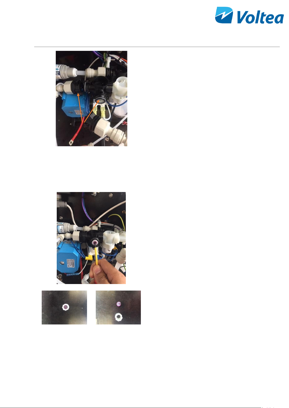
• To remove the connections holding the flow
restrictors in place, use a flathead screwdriver to
hold the latching mechanism in place, whilst
rotating the black fitting counter-clockwise by 90
degrees.
• This will unlock the fitting which can then me
removed by pulling away from the assembly.
• Once the fittings are removed, use a small
flathead screwdriver to lever out the flow
restrictor, being careful not to damage the central
mechanism.
• Replace these flow restrictors with the desired
ones. First remove the old flow restrictor from the
flow restrictor housing by gently pushing with a
screwdriver. Then insert the desired flow
restrictor by reversing the procedure described
above.
• Push the black fittings back onto the valve
assembly rotating them 90 degrees clockwise to
lock in position.
NOTE: Flow restrictor change is only advised after
consulting Voltea.
Flow restrictors
Page 33
32
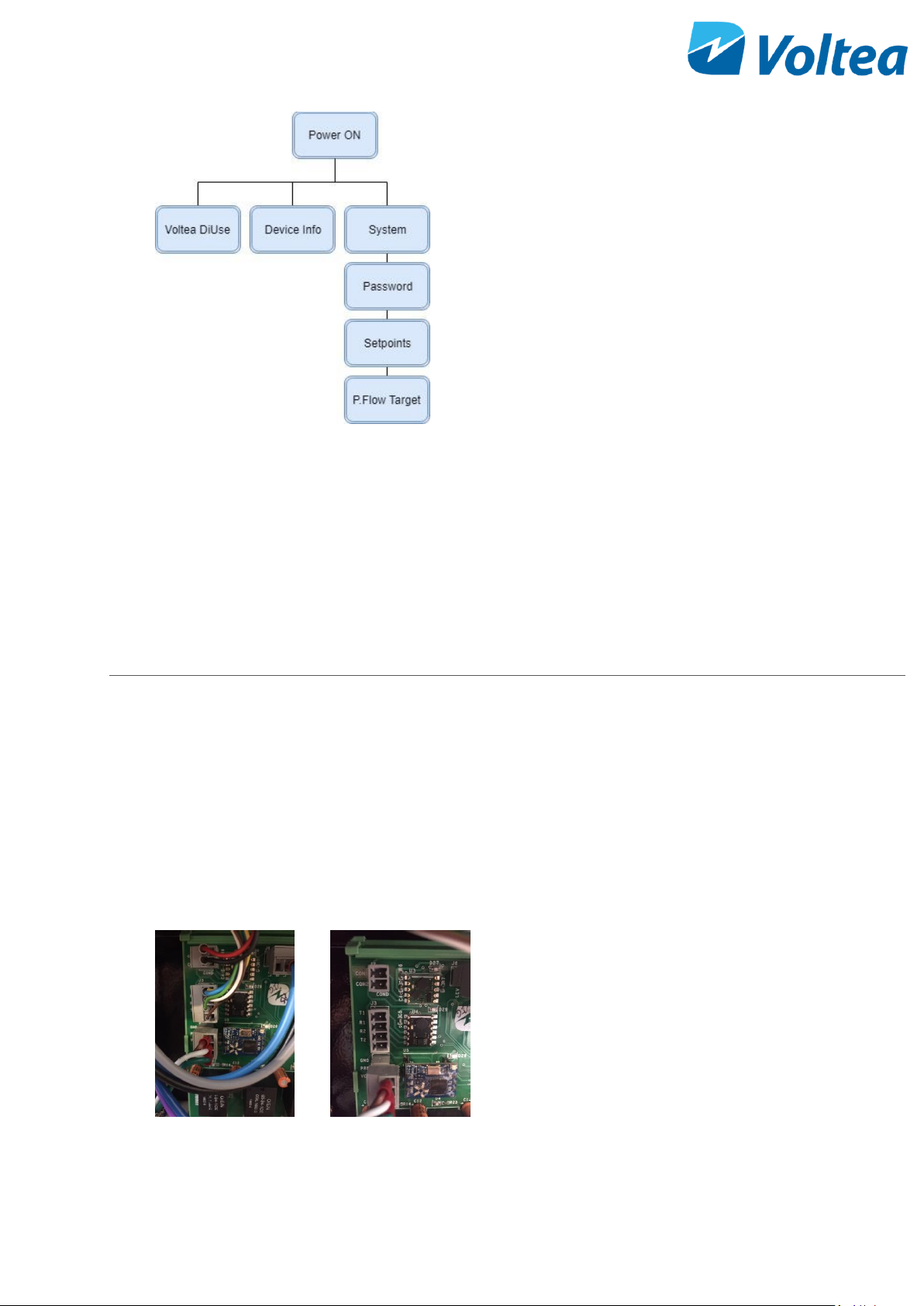
• On the LCD, update the Pure Flow Target set point
in Systems/Set Points. This value is only in liters
per minute (L/min). If adding an X l/m flow
restrictor in the High flow and a Y l/m flow
restrictor in Low flow, set the pump to X plus Y
minus 0.2, i.e. if you add a 2 l/min flow restrictor
in the high flow and 0.9 l/m flow restrictor in the
low flow, set the pump to 2.7 l/min.
• After flow restrictor replacement the low flow
pure and low flow waste alarm setpoints need to
be updated. The new value should be the low flow
restrictor value divided by 2 for waste and the
sum of the two flow restrictors values divided by
2 for pure. More about setpoints in section 8.4.1
11 ELECTRICAL CONDUCTIVITY PROBE CALIBRATION
Equipment needed:
• Temperature probe (capable of reading atmospheric temperature)
• Calibration solution, Voltea recommends 147 μS/cm standard solution.
• Phillips screwdriver.
• External EC probe.
• External mounted EC probe.
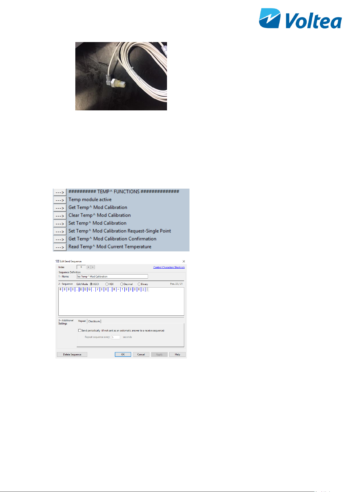
To calibrate the electrical (EC) probe, do the
following:
• Remove the flat covers
• Open the cabinet door
• Disconnect the EC probe connections
from the PCB
Page 34
33
• Connect the external EC probe on the
PCB.
• Rinse the EC probe with demineralized
water and dry with paper.
• Power on the system
Conductivity probe is calibrated through
Docklight. Before EC calibration, temperature
has to be calibrated.
For more information on how to use Docklight
please refer to chapter 9.2.1. Open the program
and perform the following by pressing the Send
button.
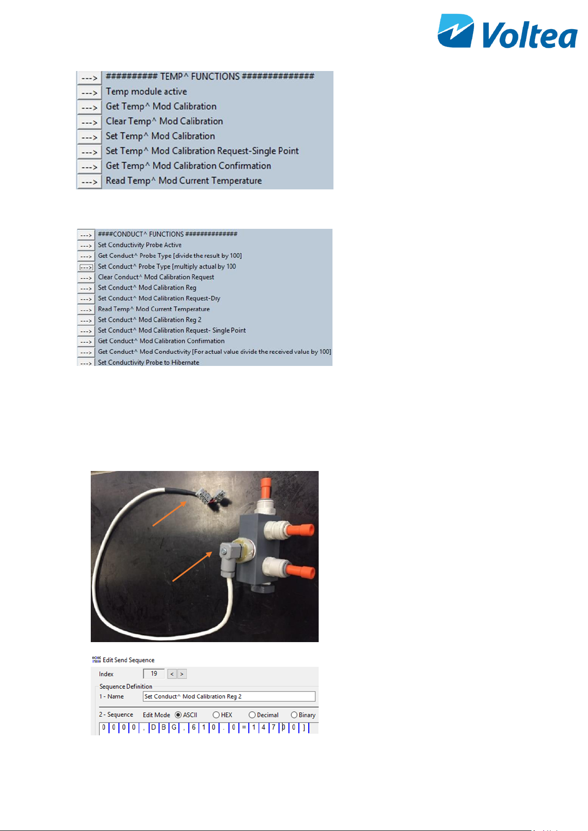
Temperature calibration:
• Click - Temp module active to activate
the probe.
• Click - Get Temp^ Mod Calibration.
• Click - Clear Temp^ Mod Calibration to
clear any previous calibration request.
• Read current room temperature using an
external probe
• Click on the text of the Set Temp^ Mod
Calibration to set temperature
according to the room temperature
measured in previous step. A pop up
window will open. By default, the
temperature is set to 25 degrees Celsius
(25000 in Docklight). Replace this value
with the room temperature measured
via the external probe, e.g. if the probe
reads 18 ﮿C the value in Docklight should
be 18000.
Note: If the probe is not at room
temperature, wait for 5 minutes for it to
reach room temperature before
calibrating. Clicking the Read Temp^
Mod Current Temperature will display
on screen the probe temperature
reading. When this reading is stable the
probe reached room temperature.
Page 35
34
• Click - Set Temp^ Mod Calibration
Request-Single Point to calibrate the
temperature.
• Click – Get Temp^ Mod Calibration
Confirmation to confirm calibration.
• Clicking - Read Temp^ Mod Current
Temperature will display the
temperature reading of the probe.
Conductivity calibration:
• Click - Set conductivity Probe Active to
activate the EC probe.
• Click - Set Conduct^ Probe Type
• Click - Get Conduct^ Probe Type
Response should be “100”.
• Click - Clear Conduct^ Mod Calibration
Request to clear previous calibration
requests.
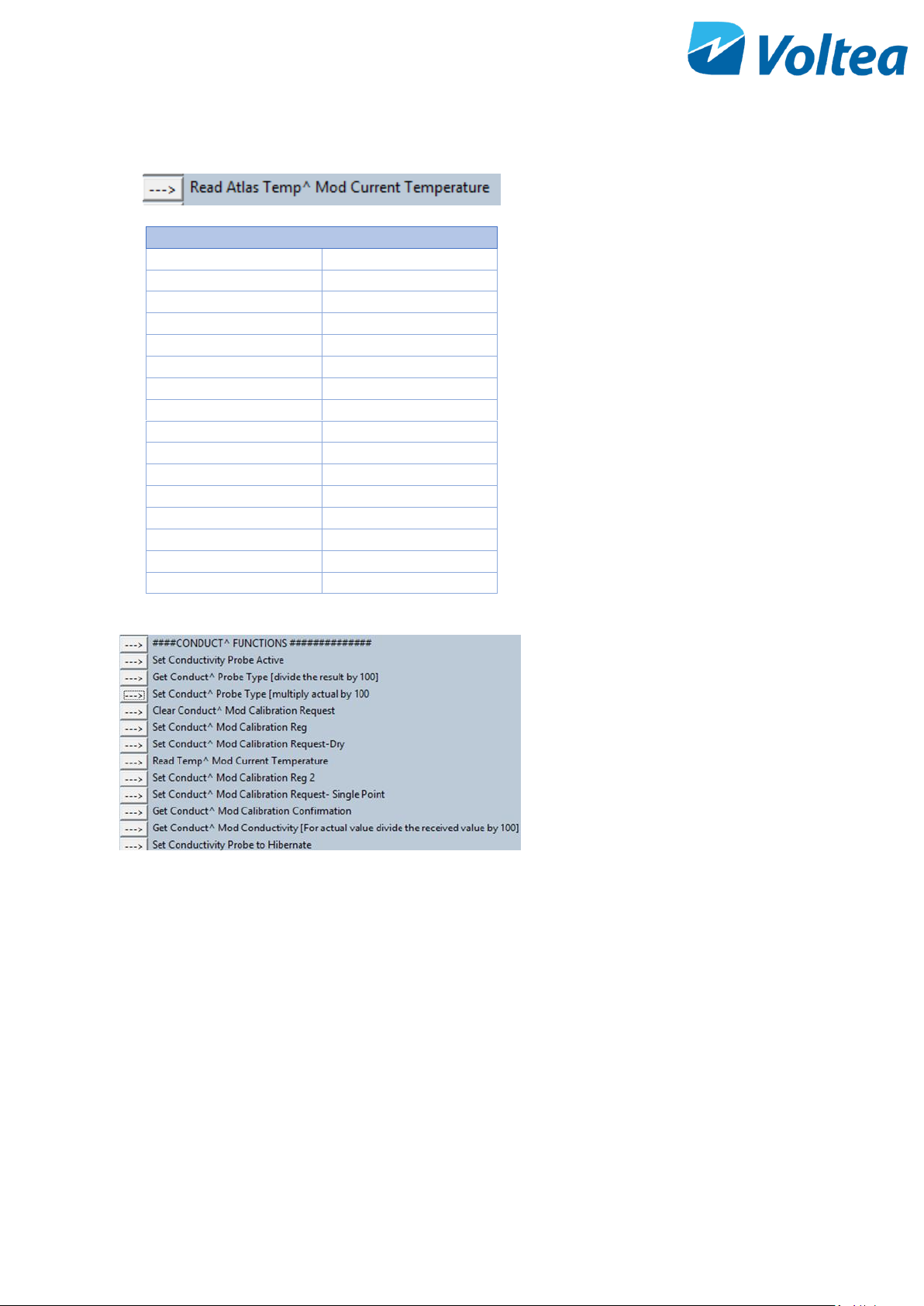
• Click - Set Conduct^ Mod Calibration
Reg. Make sure the probe is not in
contact with any liquid or surface.
• Click - Set Conduct^ Request-Dry, to
calibrate for dry.
• Disconnect the external EC probe from
the PCB and connect the EC probe
mounted on the special manifold.
NOTE: If only one cable with PCB connections is
available unscrew the EC probe cable from the
external EC probe and connect it to the mounted
one.
• Fill the manifold with the calibration
solution. Voltea suggests using a
147µS/cm standard solution.
• If a different calibration solution is used,
click on the Set Conduct^ Mod
Calibration Reg 2 command. A new
window will pop up. Input your desired
calibration value and add two times zero
at the end. E.g. if a 300 µS/cm calibration
PCB connections
EC probe cable part
Page 36
35
Temperature (°C)
EC (µS/cm)
15
119
16
122
17
125
18
127
19
130
20
133
21
136
22
139
23
142
24
145
25
147
26
150
27
153
28
156
29
159
30
162
solution is used delete the 14700 preset
value and add 30000, click OK.
• The calibration value should be
uncompensated for temperature. If you
don’t know the calibration solution
temperature, you can use the
Read Temp^ Mod Current Temperature
command to read the calibration
solution temperature, e.g. the 147
µS/cm solution has this EC only at 25°C.
If the solution temperature is 20°C the
EC value used for calibration should be
133 µS/cm.
• Click - Set Conduct^ Mod Calibration
Reg 2 to save the conductivity value of
the calibration solution used.
• Click - Set Conduct^ Calibration Request
- Single Point to calibrate the probe.
• Click - Get Conduct^ Mod Calibration
Confirmation to receive confirmation
• Click - Get Conduct^ Mod Conductivity
to get a conductivity measurement.
• Click - Set Conductivity Probe to
Hibernate.
• Click - Reset controller to save all
changes to the PCB.
• Disconnect the calibration EC probe and
re-connect the system EC probe on the
PCB. Disconnect the USB cable and close
the cabinet. Jumper should remain in the
open position.
Page 37
36
12 FLUSHING, BLEACHING, STORING AND MODULE DISPOSAL
12.1 FLUSHING THE MODULE
Flushing the module is required for at least 15-20
minutes before starting operation for the first time. To
flush the module, select the built in function via the LCD
screen.
12.2 BLEACHING THE MODULE
Bleaching the module before storing is highly
recemented. To bleach the module a 120-ppm free
chlorine solution is needed. Non-scented household
bleach can serve as the free chlorine source. The free
chlorine concentration in a typical household bleach
product is 8.5%, in this case dilute by adding 1.4mL of
bleach into the 1L of water.
Fill the CIP container with the 120-ppm free chlorine
solution. Through the main controls go to RELAY TEST and
open the CIP Pump (CIP) and Waste valve (WOV). This will
allow the chlorine solution to insert the module and be
discharged through waste line. Close both when the CIP
container is empty.
12.3 STORAGE
In case of module long term storage (>3 days), it is advised that after the last period of operation and before the
long break, an aqueous solution containing 30g/L NaCl, 2g/L glycolic acid and 1g/L Sodium Benzoate is flushed
through the module for 5 minutes. After flushing the module should be sealed with the orange stoppers.
NOTE: Clean or sterile water should be used for the storage solution.
If the period of no operation is longer than 1 month, the storage solution should be replaced every month.
Page 38

37
An alternative solution with a longer storage period using a bio-growth inhibitor is available, please contact
Voltea for more information.
12.4 DISPOSAL
When (parts of) the DiUse has reached the end of its serviceable life time the following must be observed before
disposing:
• Some parts may be reused so please contact Voltea before disposing DiUse.
• The system should be discharged in accordance with legislation in force locally.
• Materials should be reused or disposed in an environmentally friendly manner.
• Throughout operation and depending on the application a CapDI module may have been exposed to
and may have accumulated harmful components. The user is responsible for proper disposal in
accordance with local legislation.
13 SYSTEM MAINTENANCE
To ensure continuous and untroublesome operation, Voltea suggests a weekly check. You can find the weekly
check form in the Appendix.
Pure electrical conductivity, the alarm list and the CIP solution level is advised to be checked weekly.
Fan filter and the check valves in the manifold should be checked at least every 6 months.
Page 39
38
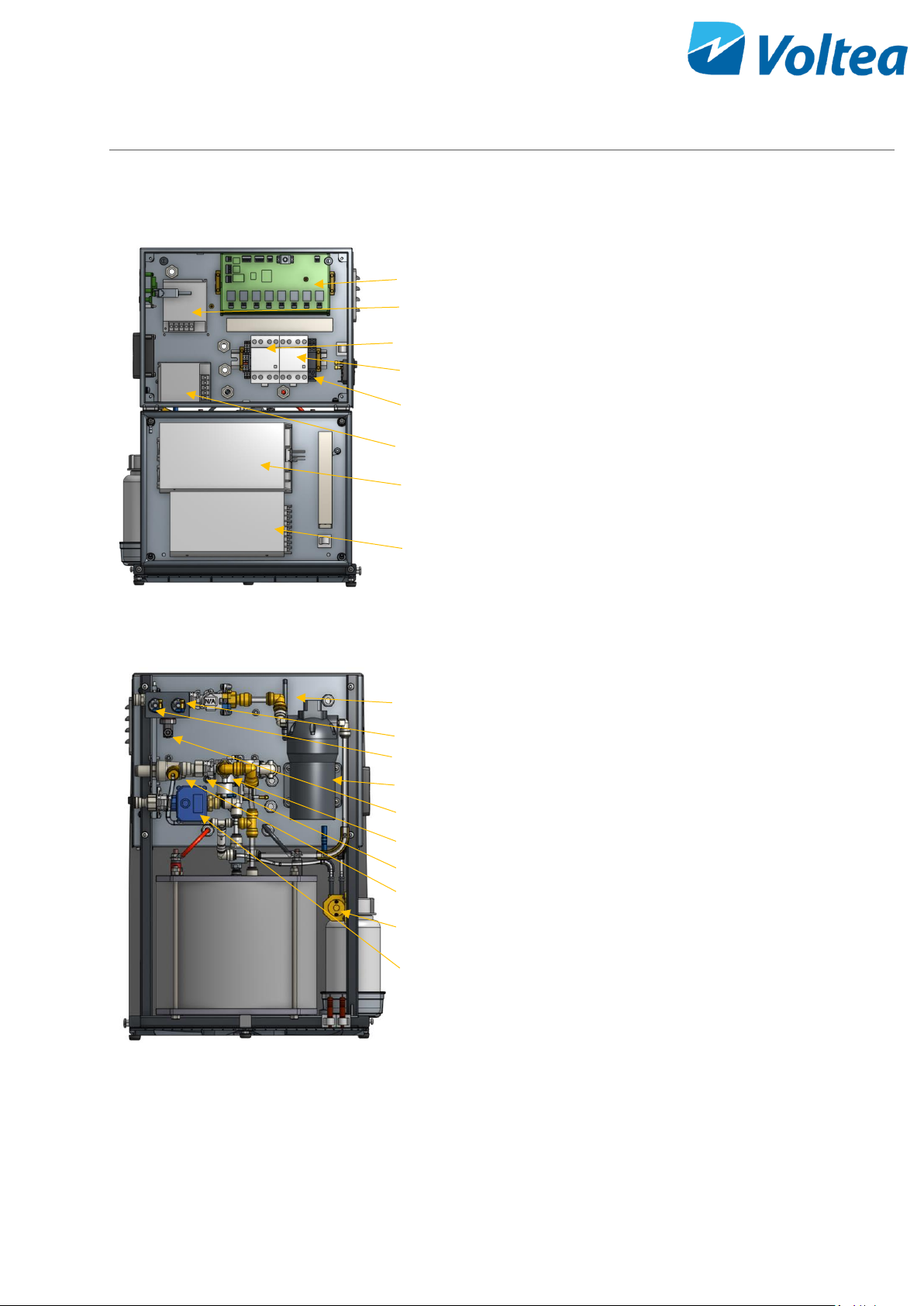
14 SYSTEM COMPONENTS
14.1 ELECTRIC CABINET
1. PCB
2. Power supply (24V - 50W)
3. Shunt relay
4. Main relay
5. PAE reset relay
6. Power supply (24V - 50W)
7. Power supply (12V - 800W)
8. Power supply (12V - 150W)
14.2 VALVES, SWITCHES AND PUMPS
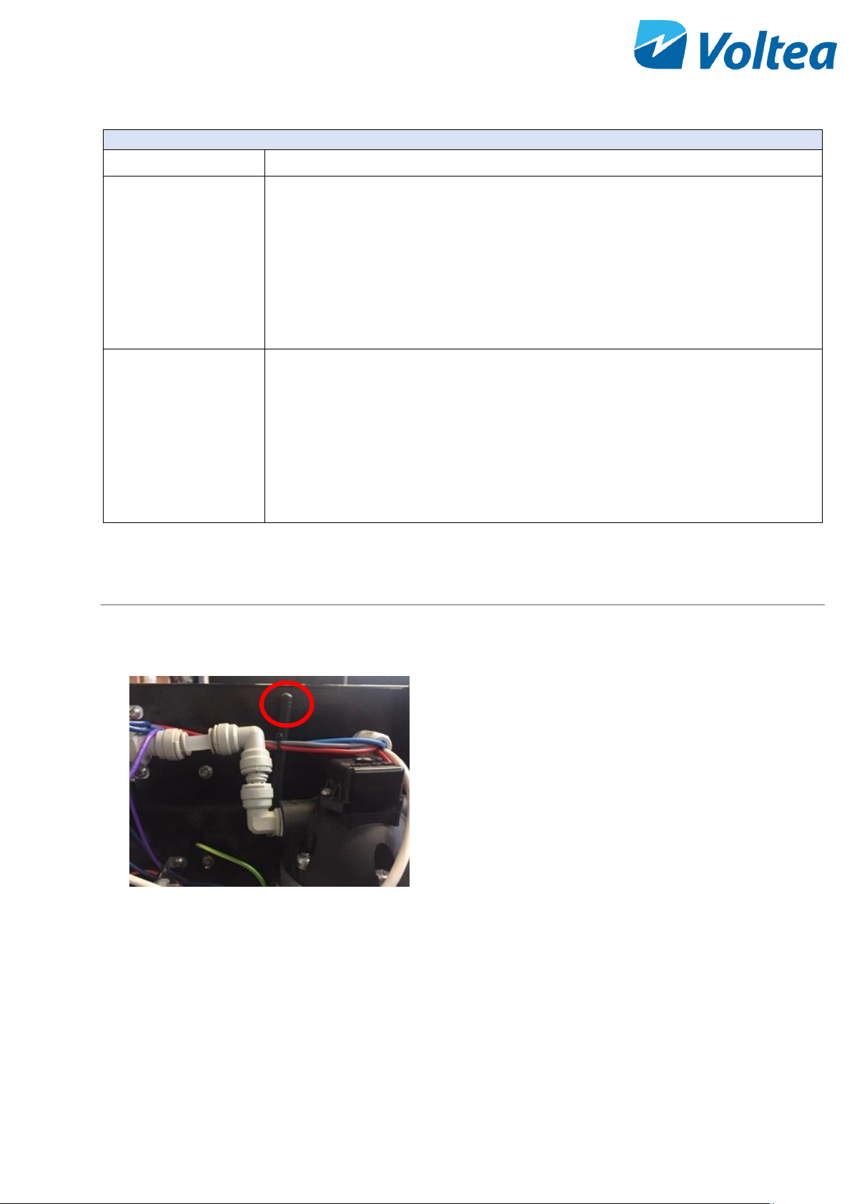
1. GSM antenna
2. Pressure switch 2 bar (29 psi)
3. Pressure switch 3.5 bar (50.7 psi)
4. System pump
5. EC probe
6. Solenoid valve
7. Flow meter
8. Solenoid valve
9. CIP pump
10. Motor valve
1 2 3 4 5 6 7 8 9
10
1
2 3 4 5 6 7 8
Page 40
39
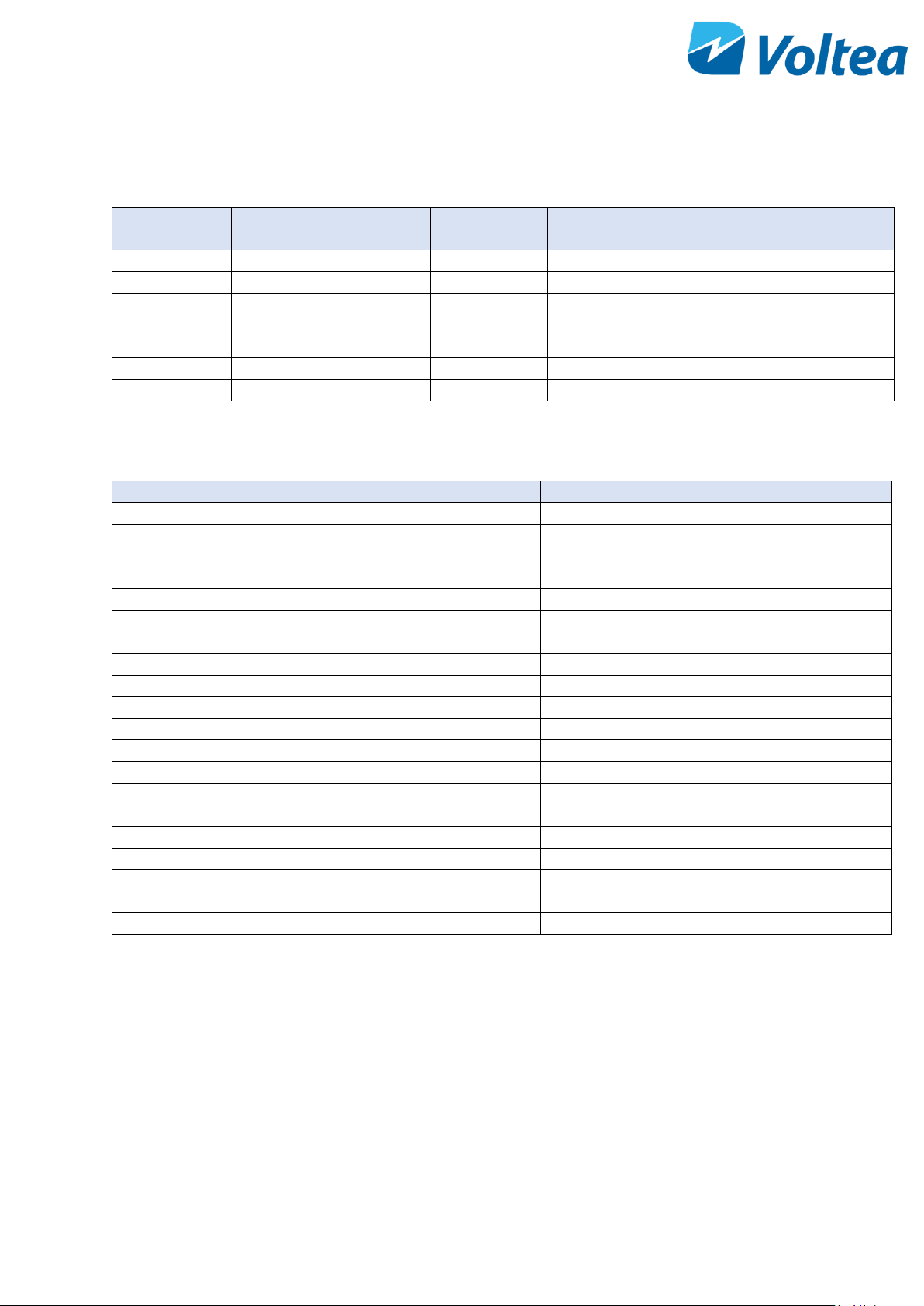
APPENDIX
FLOW RESTRICTOR COLOR AND FLOW
Order
Number
Color
Flow (L/m)
Flow (gpm)
Availability
102238
Red
0.25
0.06
Shipped with DiUse
102239
Lime
0.50
0.13
Shipped with DiUse
102014
Cyan
0.90
0.23
Pre-installed in low flow
102240
White
1.10
0.29
Shipped with DiUse
102241
Yellow
1.70
0.44
Shipped with DiUse
102015
Violet
2.15
0.56
Pre-installed in high flow
102242
Black
2.70
0.71
Shipped with DiUse
SPARE PARTS LIST
Voltea part #
Description
101839
Motor valve
102013
Flow meter
102684
Pressure switch 3.5 bar
102683
Pressure switch 2.0 bar
102022
Flow meter
102018
Solenoid valve A
102661
ADDA 80 mm fan
102019
Solenoid valve C
102377
Acid peristaltic pump
102028
Acid check valve
101414
Nut M8 fine thread
101477
Nut M8
102244
C-5-24 DDRG Module
102677
PCB 1.3
101796
800W power supply
102652
System pump
102047
63A relay
102024
150W power supply
102066
50W power supply
102394
PAE relay
Page 41

40
50% W/W CITRIC ACID SOLUTION PREPARATION
1. Required materials
a. Citric acid (solid, >95%, no specific grade)
b. 1L (0.26 gallons) graduated container
c. Stirring rod or stirring device
d. Personal protective equipment, as described in the citric acid data sheet.
e. Distilled/sterile water
2. Fill the container with 500 ml (0.13 gallons) distilled/sterile water
3. Weigh out 624g (1.37 pounds) of citric acid.
4. Add acid to water and gradually stir.
NOTE: Add acid to water instead of water to acid to reduce the risk of splashing corrosive solution.
NOTE: It expected that the solution will become colder. If citric acid stops dissolving gently heat the
solution to increase solubility.
5. Once all the citric acid is dissolved fill the container with distilled/sterile water and stir.
Page 42
41
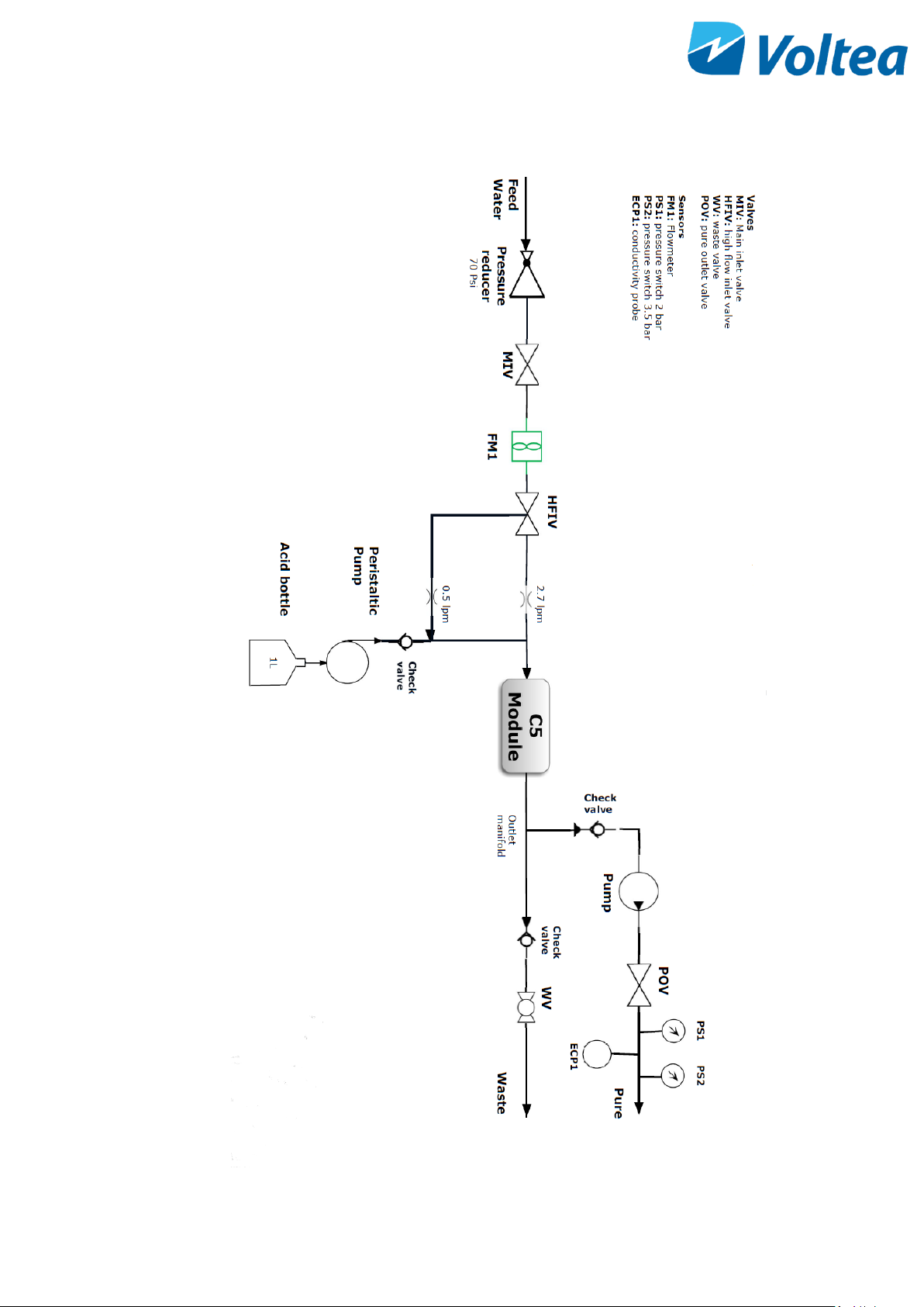
P&ID
Page 43
42
PROCESS FLOW DIAGRAM
Page 44
43
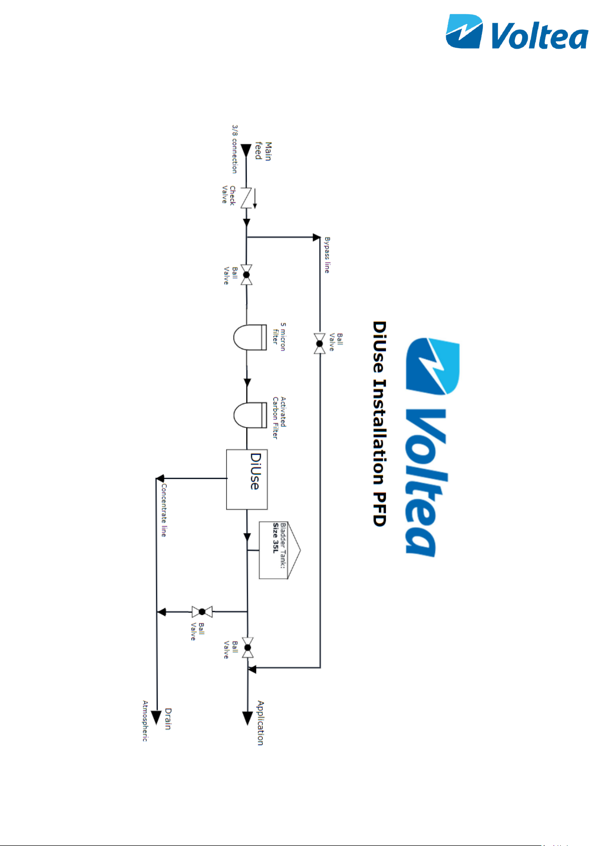
DIUSE INSTALLATION PFD
Page 45
44
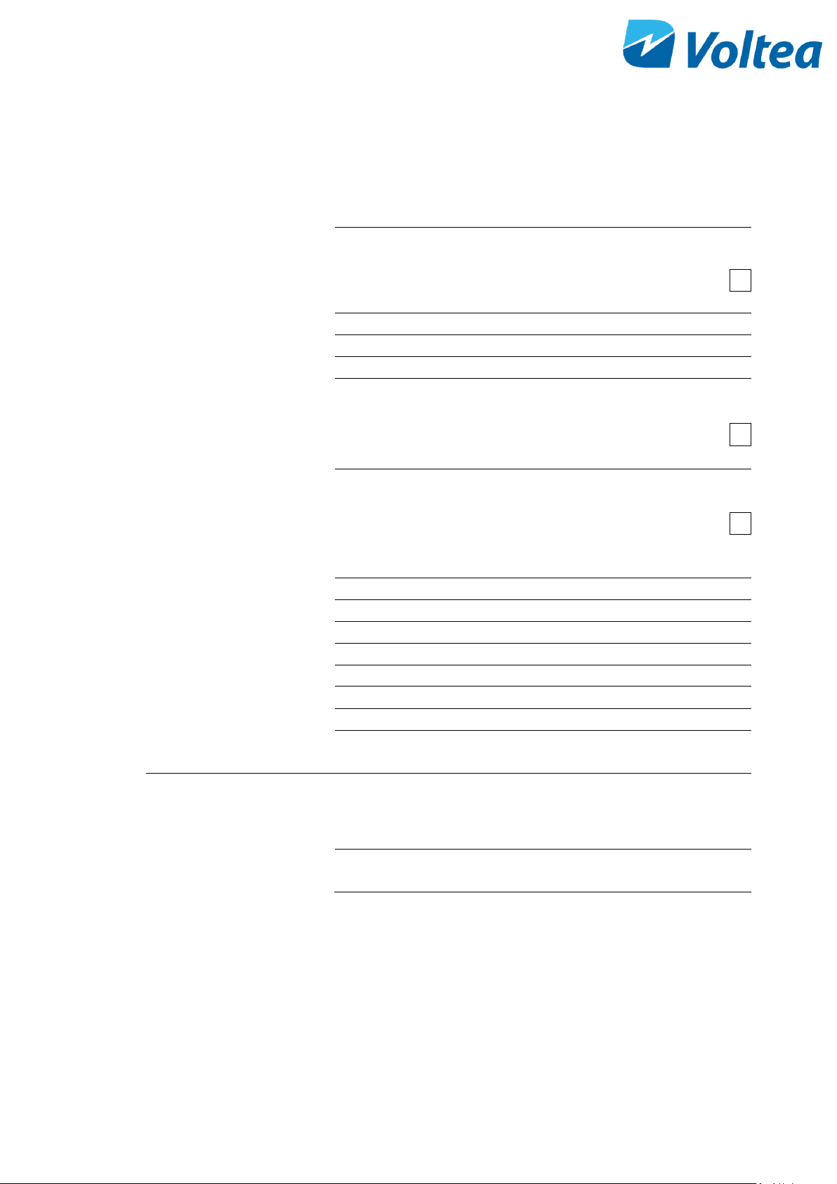
WEEKLY CHECKLIST SHEET
Date
1
Alarms
No Alarms
Alarms:
2
Water
EC on target
EC (μs/cm)
3
CIP solution
CIP solution above minimum level
4
Notes
Completed by
Signature
 Loading...