

Voltea DiUse Installation, Operation And Service Manual
1
The installation, service and maintenance of this equipment should be rendered by a qualified and trained
technician. This manual is written specifically for these individuals and is intended for their use. Untrained
individuals who use this manual assume the risk of any resulting property damage or personal injury.
The DiUse system meets the essential safety and health requirements of the European Union. This means that
DiUse can be operated and maintained safely if all safety precautions are considered. However, dangerous
situations can occur due to injudicious or negligent use of the system.
NOTE: The DiUse system is not intended for use with water of unknown quality.
NOTE: The DiUse system is to be supplied with cold water.
WARNING!
Electrical shock hazard! Prior to servicing equipment,
disconnect power supply to prevent electrical shock.
WARNING!
Electrical shock hazard: Located on the electrical cabinet
door and inside the electrical cabinet. The electrical
cabinet may never be opened when the system is
producing water.
WARNING!
If incorrectly installed, operated or maintained, this
product can cause severe injury. Those who install,
operate or maintain this product should be trained in its
proper use, warned of its dangers, and should read the
entire manual before attempting to install, operate or
maintain this product.
CAUTION!
This product is not to be used by children or persons with
reduced physical, sensory or mental capabilities, or lack
of experience or knowledge, unless they have been given
supervision or instruction.
CAUTION!
If the power cord of the unit looks or becomes damaged,
the cord should be replaced by a Voltea service engineer
or similarly qualified person to avoid hazard.
All rights reserved. No part of this publication may be reproduced, stored in a database or retrieval system, published in any form or in any way, electronically,
mechanically, by print, photo print, microfilm or any other means without prior written permission from the manufacturer. All Voltea trademarks and logos
are owned by Voltea B.V. All other brand or product names are trademarks or registered marks of their respective owners. Because we are continuously
improving our products and services, Voltea reserves the right to change specifications without prior notice. Voltea is an equal opportunity employer. DiUse
Owner’s Guide: Copyright © 2018
EUROPEAN OFFICE
Wasbeekerlaan 24
2171 AE Sassenheim, Netherlands
+31(0)252.200.100
US OFFICE
1920 Hutton Court #200
Farmers Branch, TX 75234
+1(469)620.0133

2
CONTENTS
1 DiUse Manual .................................................................................................................................. 4
1.1 General safety precautions ..................................................................................................... 5
2 Liability and Warranty ..................................................................................................................... 5
2.1 Liability .................................................................................................................................... 5
2.2 Warranty ................................................................................................................................. 5
3 Voltea CapDI - Membrane Capacitive Deionization ........................................................................ 5
4 DiUse ............................................................................................................................................... 7
4.1 Features .................................................................................................................................. 7
4.2 Specifications .......................................................................................................................... 7
4.3 Feed water quality .................................................................................................................. 8
5 System Overview............................................................................................................................. 9
6 System Installation ........................................................................................................................ 10
6.1 Packing .................................................................................................................................. 10
6.2 Tools and materials ............................................................................................................... 10
6.3 Module installation ............................................................................................................... 10
6.4 Placing leak sensor ................................................................................................................ 12
6.5 Placing the covers. ................................................................................................................ 12
6.6 Water connections ................................................................................................................ 13
6.7 Powering the system up/down ............................................................................................. 13
6.8 replacement of CIP solution .................................................................................................. 13
6.9 Flushing the module.............................................................................................................. 14
7 System Start Up - Operation ......................................................................................................... 15
7.1 Operation with pressurized tank .......................................................................................... 15
7.2 Operation with atmospheric tank ......................................................................................... 15
7.3 System pump ........................................................................................................................ 16
8 System Control Through LCD ........................................................................................................ 16
8.1 DiUse Screen Navigation Chart ............................................................................................. 17
8.2 Voltea DiUse .......................................................................................................................... 17
8.2.1 Process steps ................................................................................................................. 18
8.2.2 Alarms ........................................................................................................................... 19
8.3 Device info ............................................................................................................................ 20
8.4 System ................................................................................................................................... 20
8.4.1 Setpoints ....................................................................................................................... 21
8.5 User functions ....................................................................................................................... 23

3
9 Advance System Functions ........................................................................................................... 23
9.1 Receive data and alarms remotely ....................................................................................... 23
9.2 Connecting to laptop and utilizing docklight ........................................................................ 24
9.2.1 Laptop connection ........................................................................................................ 24
9.2.2 Docklight ....................................................................................................................... 26
9.2.3 Downloading operational data from the system .......................................................... 28
9.2.4 Adding e-mail and telephone users. ............................................................................. 29
9.2.5 Daily summary report ................................................................................................... 29
9.2.6 Remote control through SMS ....................................................................................... 30
10 Changing Flow Restrictors ......................................................................................................... 31
11 Electrical Conductivity Probe Calibration ................................................................................. 32
12 Flushing, Bleaching, Storing and Module Disposal ................................................................... 36
12.1 Flushing the module.............................................................................................................. 36
12.2 Bleaching the module ........................................................................................................... 36
12.3 Storage .................................................................................................................................. 36
12.4 Disposal ................................................................................................................................. 37
13 System maintenance ................................................................................................................. 37
14 System Components ................................................................................................................. 38
14.1 Electric cabinet ...................................................................................................................... 38
14.2 Valves, switches and pumps ................................................................................................. 38
Appendix ............................................................................................................................................... 39
Flow restrictor color and flow ........................................................................................................... 39
Spare parts list .................................................................................................................................. 39
50% w/w citric acid solution preparation ......................................................................................... 40
P&ID .................................................................................................................................................. 41
Process flow diagram ........................................................................................................................ 42
DiUse installation PFD ....................................................................................................................... 43
Weekly checklist sheet ...................................................................................................................... 44
4
1 DIUSE MANUAL
This manual:
• Familiarizes the user with the equipment.
• Explains installation and setup procedures.
• Provides basic programming information.
• Explains the various steps of operation.
• Gives specification information.
Read this manual first: Before you operate DiUse, read this manual to become familiar with the device.
Through this manual, special symbols will appear:
NOTE
Is used to emphasize information related with installation,
operation and maintenance without highlighting any
hazard.
WARNING!
Warning is used to indicate a hazard which could cause
injury or death if ignored.
CAUTION!
Caution is used when failure to follow directions could
result in damage to equipment or property.
The WARNING and CAUTION signs are not meant to cover all possible conditions and situations that may occur
during installation, maintenance and operation. Understand that common sense, caution and careful attention
is always needed.
Before installing be sure to check all applicable plumbing codes and ordinances. Local codes and legislation may
prohibit the discharge of sanitizing or descaling solution to drain. The system and installation shall comply with
applicable state and local regulations.
Always use protective clothing and proper face or eye protection when handling chemicals and tools.
The CapDI system meets the essential safety and health
requirements of the European Union. This means that the
system can be operated and maintained safely if all safety
precautions are observed. However, dangerous situations can
occur due to injudicious or negligent use of the CapDI system.
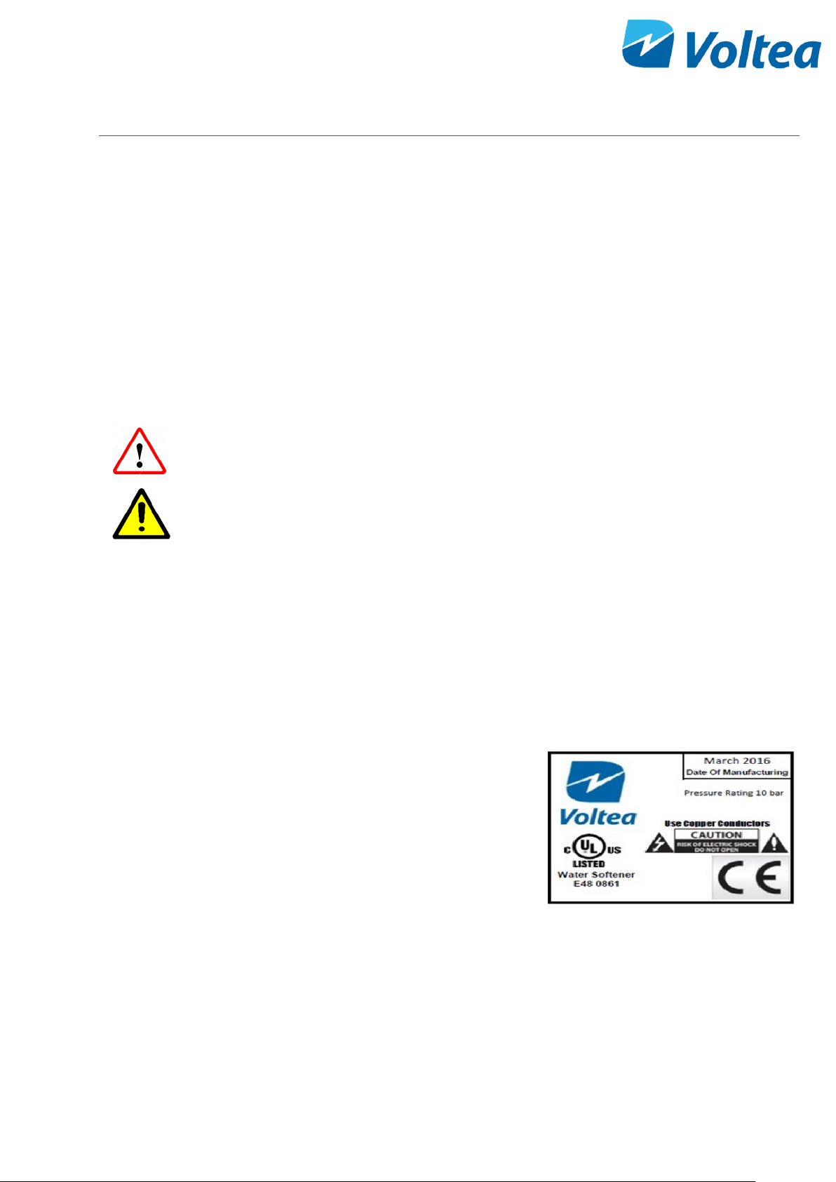
If a UL mark is attached to the system, then it has performed
to UL standards and is certified.
The DiUse system conforms to NSF/ANSI 42, for specific performance claims as verified and substantiated by
test data.

5
1.1 GENERAL SAFETY PRECAUTIONS
Observe the following general safety precautions:
• Check the proper functioning of the system daily.
• Always replace damaged or defective parts before putting the system into use again.
• Do not make modifications to the system without prior approval of the manufacturer.
• Do not open the electrical cabinet when the system is powered on.
• If chemicals are supplied, the attached safety procedures should be observed.
2 LIABILITY AND WARRANTY
2.1 LIABILITY
Voltea will, under no circumstances be held liable for any consequential damages. The recipient hereby disclaims
all representations and warranties, whether expressed or implied with respect to materials and/or prototypes.
Including without limitation any warranties of non-infringement, merchantability or fitness for merchantability
or fitness for any particular purpose save that such shall have been prepared with reasonable skill and care. The
recipient accepts all risks which may be inherent in its use of materials and/or DiUse system and shall hold
harmless and indemnify each of Voltea and its affiliates officers, director, shareholders, employees and agents
from and against any and all claims, damage, losses or other liabilities that may arise directly and solely from
recipient’s use, storage, handling or disposal of the materials and/or systems.
2.2 WARRANTY
CapDI modules supplied with DiUse have been tested and have a guaranteed performance as they have passed
Voltea’s quality control test (a certificate of analysis will be supplied with each module upon request). Voltea
does warrant workmanship (leakage, connections) of the CapDI module for a period of 1 year from shipment
provided that the CapDI module is operated within the recommended operational limits as provided in the
section 4.2 and 4.3. Voltea does not warrant desalination and other performance aspects of the CapDI modules
within the customer application. Voltea warrants the DiUse for a period of 1 year from shipment provided that
the system is operated in accordance with this manual.
3 VOLTEA CAPDI - MEMBRANE CAPACITIVE DEIONIZATION
The CapDI system uses Capacitive Deionization technology and its function is the removal of ions from the water.
NOTE: The CapDI system does not disinfect water.
CapDI: A tunable water deionization technology that is designed to remove dissolved salts from a variety of
water sources ranging from tap water and brackish groundwater to industrial process water. CapDI achieves this
at a lower economic cost and reduced environmental impact than any other available technology.
6
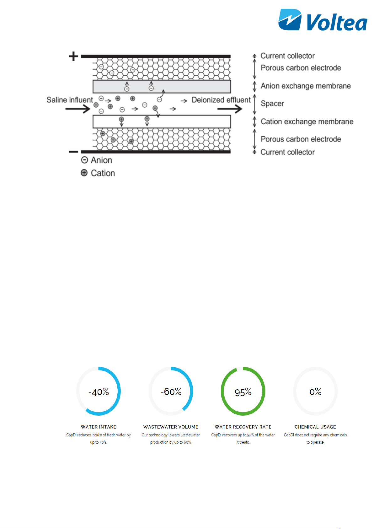
A CapDI module consists of a housing which contains multiple stacks of parallel unit cells. Each unit cell consists
of two porous carbon electrodes separated from each other by a spacer. On top of the electrodes, ion exchange
membranes are placed. The spacer between the membranes acts as a flow channel to transport the water to be
desalinated.
The water flows through a small electrical field of approximately 1.5 volts that is created over a pair of
electrodes. Dissolved ions are pulled out of the water stream, toward the electrodes. The electrodes are
separated from the water by the membranes that selectively allow only positive or negative ions to pass. CapDI
is effective at removing all type of ions from water (e.g. calcium, sodium, chloride, carbonate).
Uniquely: Our technology is environmentally friendly by its low energy consumption and minimal to no chemical
usage. Thus, allowing any unrecovered water to flow back into the ecosystem safely.
Scalable: Voltea’s technology treats water types ranging from residential consumer appliances to large-scale
industrial plants. Our systems are modular, allowing easy expansion to meet any increased water demands.
Tunable: CapDI is tunable, allowing adjustable TDS reduction between 25% - 95% depending on customer needs.
Eliminating the requirements for blending to achieve a specific water quality. The customer sets their desired
reduction rate and the CapDI maintains this level, continually adjusting itself to account for any fluctuations in
feed water characteristics.

7
4 DIUSE
Voltea’s miniaturized version of the CapDI systems, specifically made for the point-of-use applications. DiUse
softens and desalinates brackish water for homes and businesses at an advantage to traditional desalination
technologies due to it being a salt-free, chemical-free alternative. DiUse is ideal for the HoReCa industry
alongside small households.
4.1 FEATURES
• Automated system CIP (Clean-In-Place)
• Voltea’s remote monitoring and control (option)
• Pure outlet conductivity meter (0 – 10 mS/cm)
• Total flow meter (0 – 10 L/min or 0 – 2.6 gpm)
• Built in display
4.2 SPECIFICATIONS
Performance
Produced flow rate*
0.6 – 2.9 L/min (0.2 - 0.8 gpm )
Instant flow rate*
1 - 5 L/min (0.3 - 1.3 gpm)
Salt removal
25 - 95 %
Water recovery
40 - 95 %
System Specifications
Average power requirements
0.13 kW, Single Phase (110 - 240 V AC / 50 - 60 Hz)
System dimensions (L x W x H)
0.32 x 0.43 x 0. 64 m (1’10’’ x 1’5’’ x 2’1’’)
Power output to modules
0 - 65 A / 0 - 2 V DC
Weight**
17kg (37.5 lbs.)
Feed inlet coupling
3/8’’ push fit
Product outlet coupling
3/8’’ push fit
Concentrate/Waste outlet
coupling
3/8’’ push fit
Operational
Requirements
Water feed pressure
3 - 10 bar (44 - 145 psi) System is equipped with a
pressure reducer
Water pressure produced***
≤6,5 bar (95psi)
Operating ambient air
temperature
< 35 ﮿C (95 ﮿F)
8
In/Outputs
Start/Stop
Pressure switch (standard) or external signal (24 V DC)
Cleaning
Procedure
Automated cleaning with citric acid
Control (auto/manual)
Automatic: on cycles of operation
Storage
1L chemical container
Controls
Remote control / Data
monitoring
Total flow, average conductivity, average voltage, (2G
SIM card with data or locally via laptop)
Parameter change
Locally
*Depends on TDS reduction and water recovery
**Weight without module
***Depends on flow target
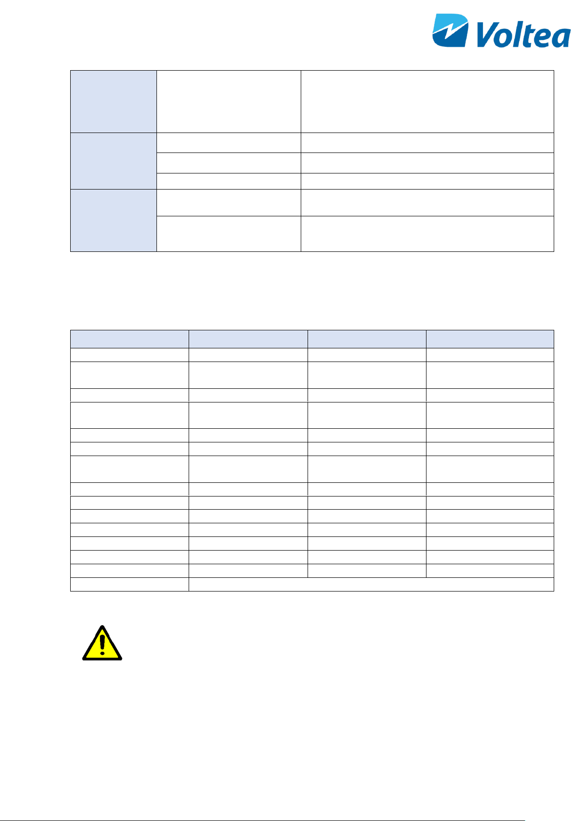
4.3 FEED WATER QUALITY
Parameter
UNIT
RANGE
INTERMITTENT
Removal limit
Δppm
0 - 1300
Total dissolved solids
(TDS)
ppm
0 - 2000
Total organic carbon
ppm
< 10
Chemical oxygen
demand
ppm
< 20
< 100
Turbidity
NTU
< 4
< 100
Fats, Oils, Greases
ppm
< 0.5
Total suspended solids
(TSS)
ppm
< 4
< 20
Free Chlorine
ppm
< 2
< 25
pH
2 – 10
1 – 12
Iron total
ppm
< 0.5
Total hardness (CaCO3)*
ppm
< 1000
M Alkalinity (CaCO3)
ppm
< 1000
Pre – filtration
µm
5
Temperature
﮿C / ﮿F
1 - 35 / 34 - 95
Chemicals
Contact Voltea
*Limit depends on set TDS reduction and water recovery
CAUTION!
5-micron filter is the minimum required pretreatment
for the feed water.
9
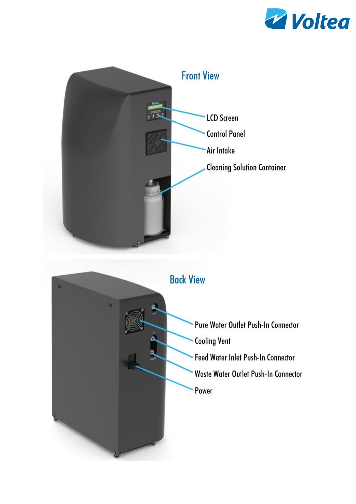
5 SYSTEM OVERVIEW
10
6 SYSTEM INSTALLATION
NOTE: Read this section entirely before starting the installation. Follow all applicable plumbing and electrical
instructions.
6.1 PACKING
• The DiUse system is shipped in two boxes.
• One box contains the module and module T-
junction, the other the DiUse frame, power
cable and spare flow restrictors.
Modules weigh 23 kg (50.7 lbs.)
6.2 TOOLS AND MATERIALS
• Safety shoes
• 2x size 13 wrenches
• Hex key number 4
• Flathead screwdriver
6.3 MODULE INSTALLATION
• Loosen the connections holding the curved
cover in place.
• Lift off the curved cover being careful of
protruding parts (e.g. air filter).
11
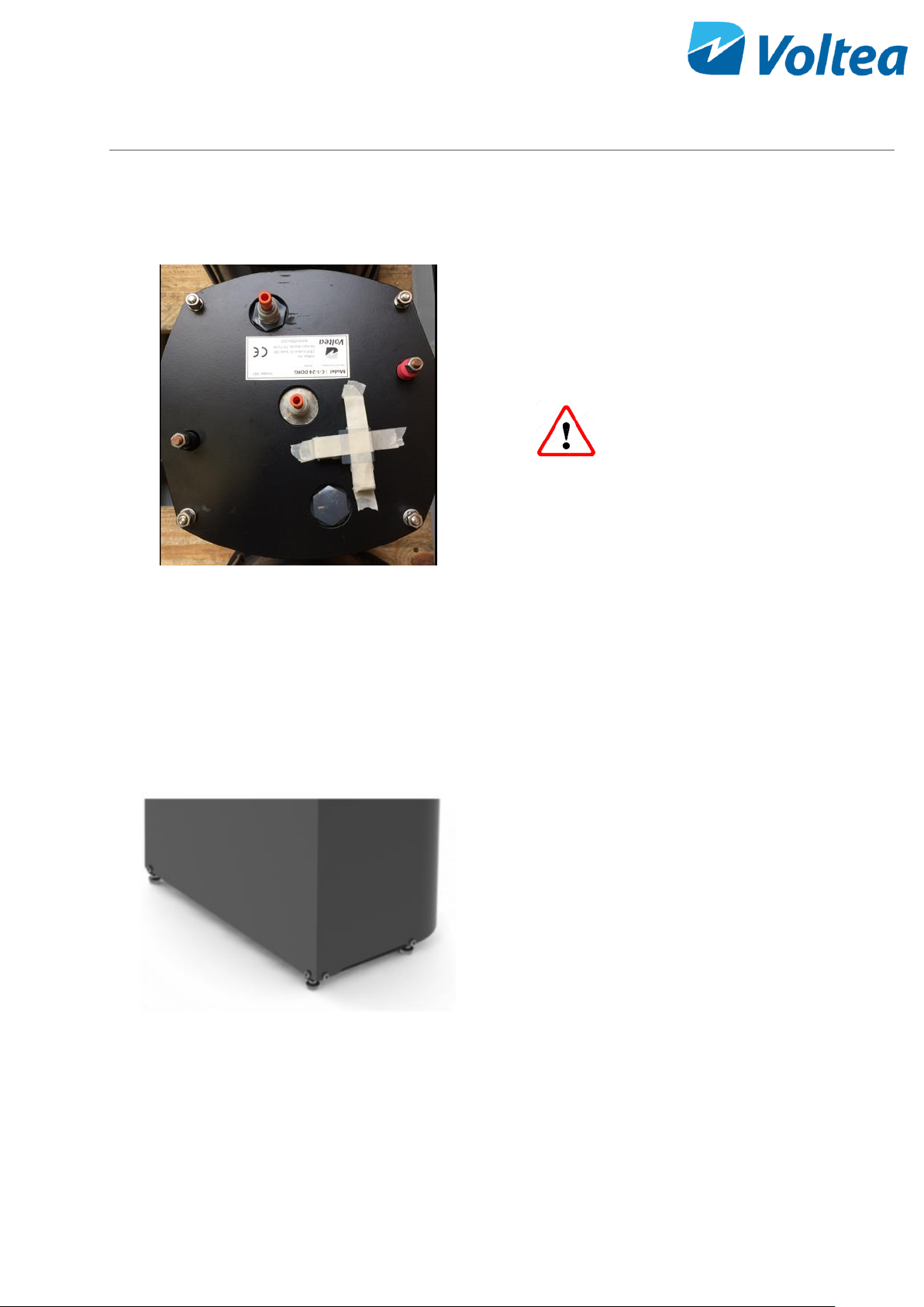
• Remove orange stoppers from module. Add
manifold to center of module using stem
adapter. The module manifold has check valves
pre-installed before each 3/8’’ push in fitting.
• Rotate the module so the red terminal is on the
left and the black terminal is on the right, when
facing the water side of the electrical cabinet.
• Push the module on the frame up against the
stoppers.
Modules weigh 23 kg (50.7 lbs.) and
the system 17 kg (37.5 lbs.). It is recommended to
wear safety shoes during installation.
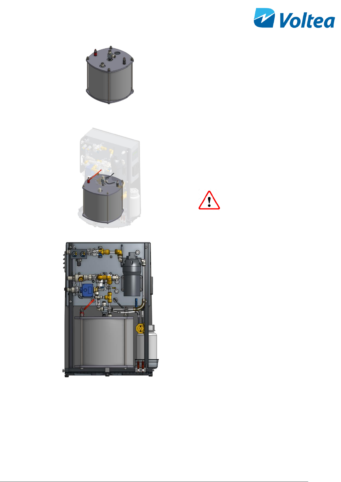
• If done correctly, the module inlet (the
connection that is NOT in the middle of the
module top) will be facing outward from the
system, and the edge of the module will be in
line with the edge of the frame.
• The vertical tube that is attached to a T-junction
should be pushed into the module outlet. If
placed correctly, pulling on the tube firmly
should not disconnect it from the module.
• The tubing that comes from the waste line
(above the center of the module) should be
pushed into the vertical connection coming
from this point.
12
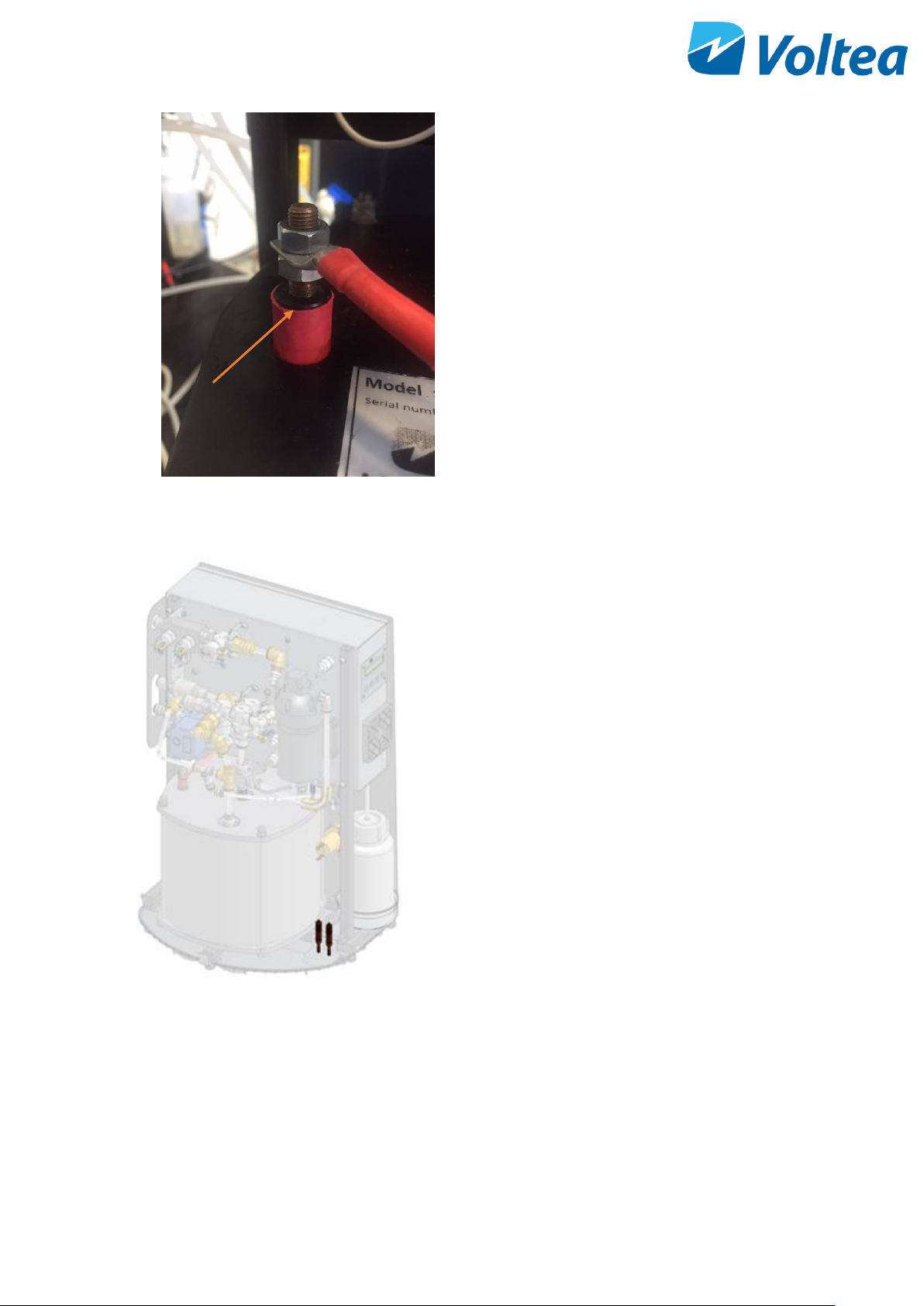
• Each module has one red and one black
electrical terminal, with each terminal having
two M8 nuts. Unscrew one of the nuts from the
red terminal. Place the red cable from the
system on the red electrical terminal, then
screw the nut back on. Tighten using two size 13
wrenches, one on the top nut and one on
bottom nut. Repeat the process with the black
terminal and black cable. Be sure the bottom
nut is isn’t sitting on the plastic bushing.
6.4 PLACING LEAK SENSOR
• Take the two sensors and place them in the
clamps as shown in the image. The tip of the
sensor should be in contact with the leak
tray.
NOTE: Leak tray should always be dry to avoid
triggering the leakage alarm and stopping the
system.
6.5 PLACING THE COVERS.
Place the covers back and tighten the connections holding the covers in place.
NOTE: Every connection has a spacer attached to it. Spacers should be between the covers and frame before
tightening.
Plastic bushing
13
6.6 WATER CONNECTIONS
Size 3/8” tubing should be used to connect the inlet to the middle connection on the side of the unit. The purified
(Out) water is discharged through the top 3/8’’ connection. Concentrate (Waste) is discharged through the
bottom 3/8’’ connection. Connections are indicated by stickers.
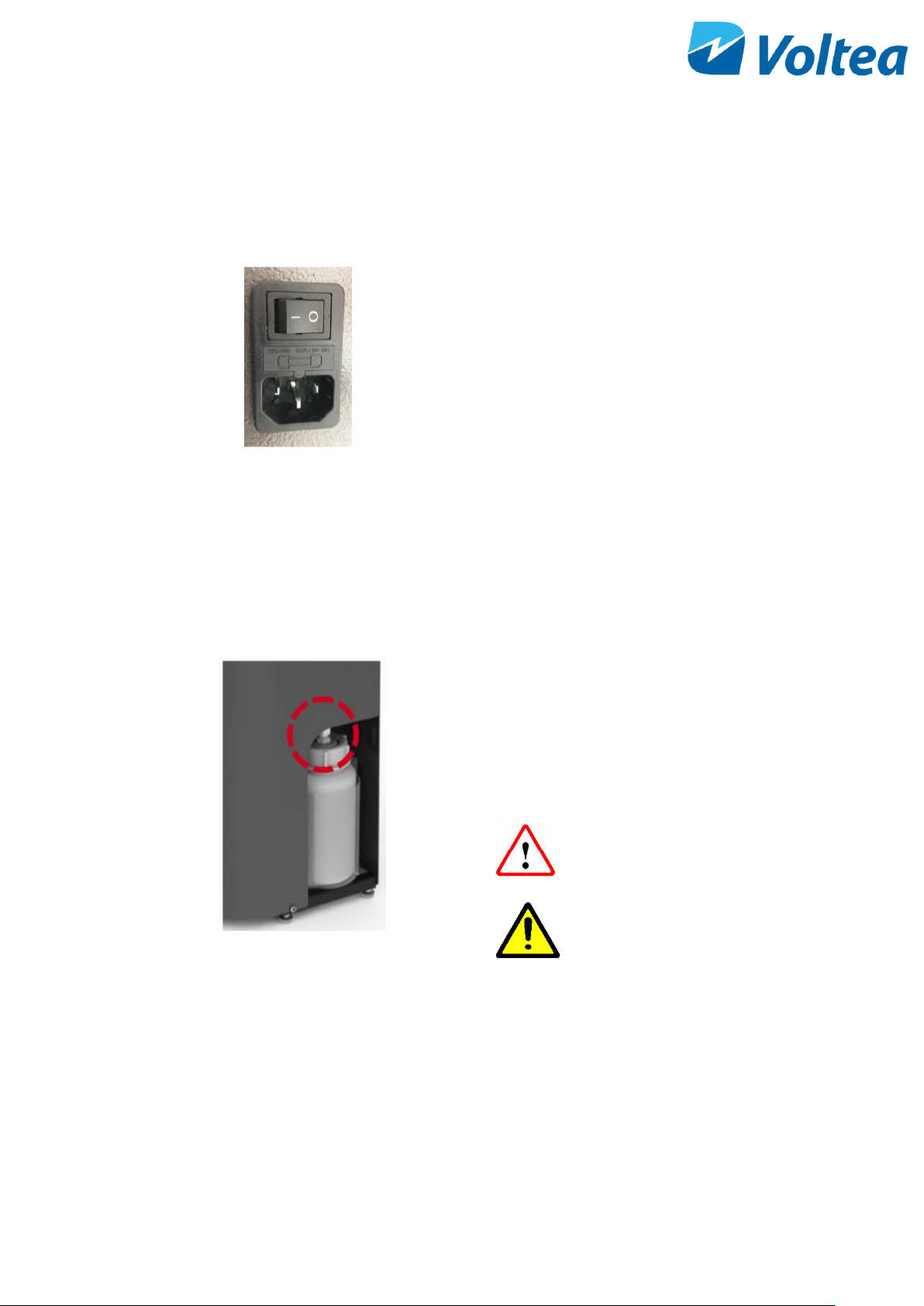
6.7 POWERING THE SYSTEM UP/DOWN
• A power cable is provided with the system.
• Connect the cable to the power connection on
side of unit.
• Turn the switch on to power the system.
NOTE: DiUse systems are specific to either 110 V or 240
V. If in doubt about system specifications, please contact
Voltea.
6.8 REPLACEMENT OF CIP SOLUTION
• Loosen the white tube gland by rotating the
gland nut (topmost piece, circled in red), whilst
holding the bottle steady.
• After the gland nut is loose, unscrew the lid of
the CIP container.
Acid may splash. Avoid
contact with eyes.
CAUTION!
If using citric acid powder
always use distilled or
sterile water for CIP
solution preparation.
 Loading...