

Voltacon 4KVA, 5KVA User Manual

1KVA-5KVA
INVERTER / CHARGER
Version: 1.2
User Manual
AUTONOMOUS SOLAR INVERTER
VOLTACON UK LIMITED | 5 ARGOSY COURT WHITLEY BUSINESS PARK | CV3 4GA | COVENTRY | UNITED KINGDOM
5 Years Manufacturer's Warranty
PARALLEL OPERATION
1
4KVA/5KVA Parallel Installation Guide
1. Introduction
This inverter can be used in parallel with two different operation modes.
1. Parallel operation in single phase with up to 4 units. The supported maximum output power is
16KW/20KVA.
2. Three units work together to support three-phase equipment, one inverter per phase. The supported
maximum output power is 12KW/15KVA.
NOTE: If this unit is bundled with share current cable and parallel cable, this inverter is default supported
parallel operation. You may skip section 3. If not, please purchase parallel kit and install this unit by
following instruction from professional technical personnel in local dealer.
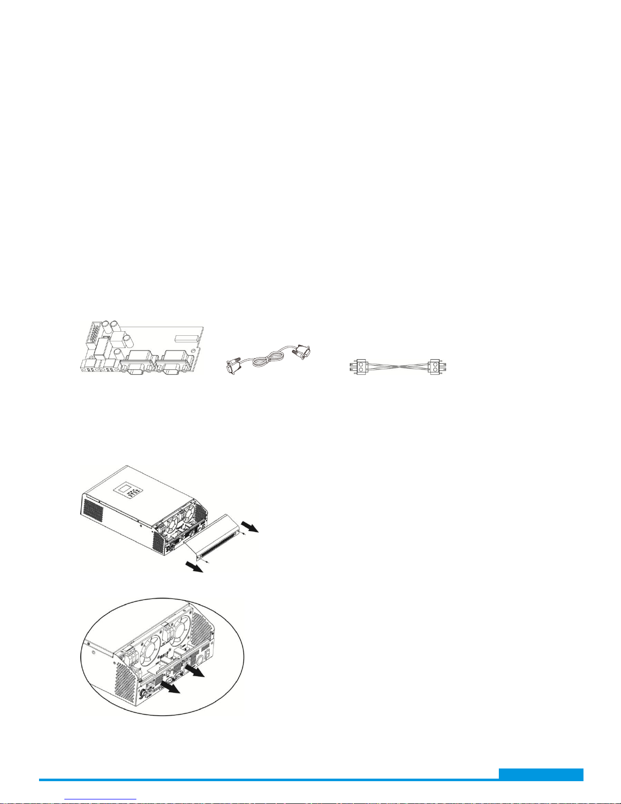
2. Package Contents
In parallel kit, you will find the following items in the package:
Parallel board Parallel communication cable Current sharing cable
3. Parallel board installation
This installation steps are only applied to 4K/5K models.
Step 1: Remove wire cover by unscrewing all screws.
Step 2: Remove communication board by unscrewing two screws as below chart.
www.voltacon.com
info@voltacon.com
2
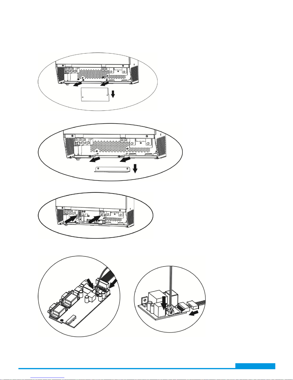
Step 3: Remove two screws as below chart and remove 2-pin and 14-pin cables. Take out the board
under the communication board.
Step 4: Remove two screws as below chart to take out cover of parallel communication.
Step 5: Install new parallel board with 2 screws tightly.
Step 6: Re-connect 2-pin and 14-pin to original position.
Parallel board Communication board
www.voltacon.com
info@voltacon.com
3
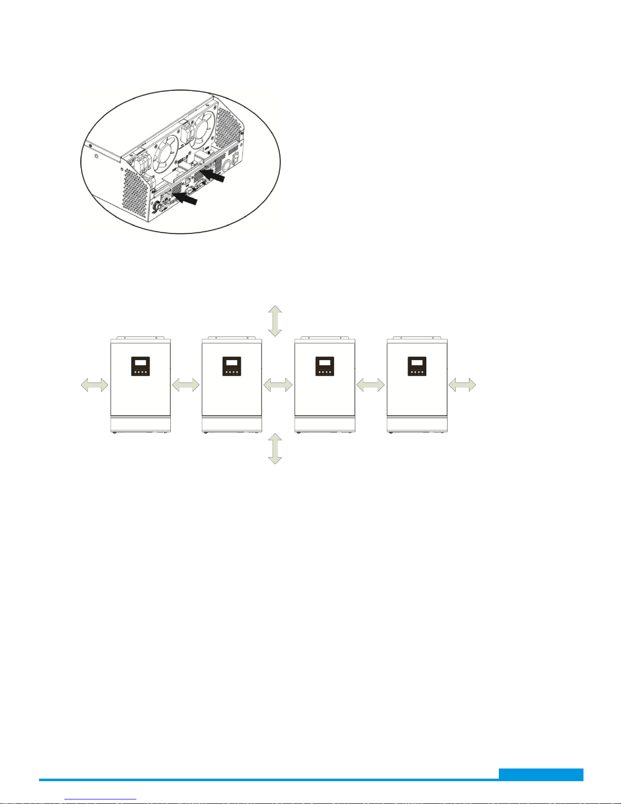
Step 7: Put communication board back to the unit.
Step 8: Put wire cover back to the unit. Now the inverter is providing parallel operation function.
4. Mounting the Unit
When installing multiple units, please follow below chart.
500mm 500mm 500mm 500mm500mm
500mm
500mm
NOTE: For proper air circulation to dissipate heat, allow a clearance of approx. 50 cm to the side and approx.
50 cm above and below the unit. Be sure to install each unit in the same level.
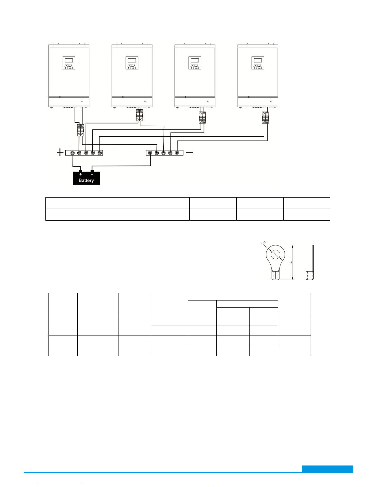
5. Battery Connection
WARNING! Be sure that all inverters will share the same sets of batteries. Otherwise, the inverters will
transfer to fault mode.
WARNING: Be sure the length of all battery cables is the same. Otherwise, there will be voltage
difference between inverter and battery to cause parallel inverters not working.
Follow below chart to connect batteries. All battery cables are connected from inverters to batteries via
the same BUS bar.
www.voltacon.com
info@voltacon.com
4
Recommended battery capacity
Inverter parallel numbers 2 3 4
Battery Capacity 400AH 600AH 800AH
NOTE: Recommended spec of cable from inverter to BUS bar and breaker is
listed as below. The cable used from BUS bar to battery should be X pcs of
cable from inverter to BUS bar and breaker. X indicates the number of
inverters connected in parallel.
Recommended battery cable and terminal size:
Model
Typical
Amperage
Battery
capacity
Wire Size
Ring Terminal
Torque
value
Cable
mm2
Dimensions
D (mm) L (mm)
4KVA 67A 200AH
1*4AWG 22 6.4 33.2
2~ 3 Nm
2*8AWG 14 6.4 29.2
5KVA 84A 200AH
1*4AWG 22 6.4 33.2
2~ 3 Nm
2*8AWG 14 6.4 29.2
Breaker
BUS Bar BUS Bar
Ring terminal:
www.voltacon.com
info@voltacon.com
 Loading...