

VOLTA FBW II Series, FBW 301, FBW 1701, FBW 2101, FBW 721 Instruction Manual
...
Welding & Fabrication Tools
FBW-Flat Butt Welding
System - Model II
Instruction Manual
The Next Step in Belting

Table of Contents
Page
How to use this manual
Symbols used in this manual
1. Introduction
2. Technical Specifications
2.1. FBW (Flat Butt Welding System Model II) Layout
2.2. The Storage Case
2.3. The Electrical System
2.4. Care and Maintenance
2.5. Safety Precautions
2.6. Warning Notice for Welding Tools
3. Welding Instruction
3.1. Preparing the Temperature Controller
3.2. Preparing the Pliers
3.3. Preparing the Belt
3
3
3
4
5
6
7
7
7
8
8
9
9
9
10
3.4. Welding the Belt
3.5. Trimming and Checking the Weld
4.
Welding Texture Top Belts
4.1.
Saw Tooth (IST) & Nub Top (NT)
4.2.
MiniCleat (MC)
4.3.
Spikes (SP)
4.4. Cresent top (CT)
5. Instructions for Splicing Reinforced Flat Belts
6. Instructions for Welding Narrow Belts
7. Instructions for Welding H Material Belts
8. Welding Positive Drive Belts
8.1. Instructions for Welding SuperDrive™ H/M Material Belts
8.2. Instructions for Welding SuperDrive™ Belts Using FBW Adapter
8.3. Positioner for Welder
8.4. Welding DualDrive
8.5. Welding Mini SuperDrive™ and Mini DualDrive™ Belts
TM
Belts
11
12
13
13
14
15
17
18
19
19
20
20
22
22
23
25
8.6. Welding Mini SuperDrive™ MiniCleat Belt
8.7. Welding DualDrive™ SP (DDSP) Belts and DDSP Lace
8.8. Welding Volta Hinge Lace
9. General Tips
10. Troubleshooting Guide
11. FBW System Model II Shinko Controller and Welder Electrical Diagram
12. Calibrating the FBW Welder System Model II Shinko Controller
13. Pitch Gauge Measuring Tool for the Positive Drive Belts
27
29
31
33
33
34
35
37
Thank you for buying the Volta FBW Welding Kit. If you have any questions about the use of this
tool please contact our Technical Service Department at email: sales@voltabelting.com or visit our
website www.voltabelting.com.
How to Use this Manual
This manual has been designed to provide the operator with all the necessary information on how to use the above tool
correctly. Warnings in the manual should be carefully followed for your personal safety. Be sure you carefully read the
instructions in this manual before using the tool. This will ensure use in compliance with safety standards.
Symbols Used in the Manual
This symbol is used for important Notes & Tips
This symbol is used to warn you of actions that are dangerous for the operator.
Read the associated warnings and instructions carefully.
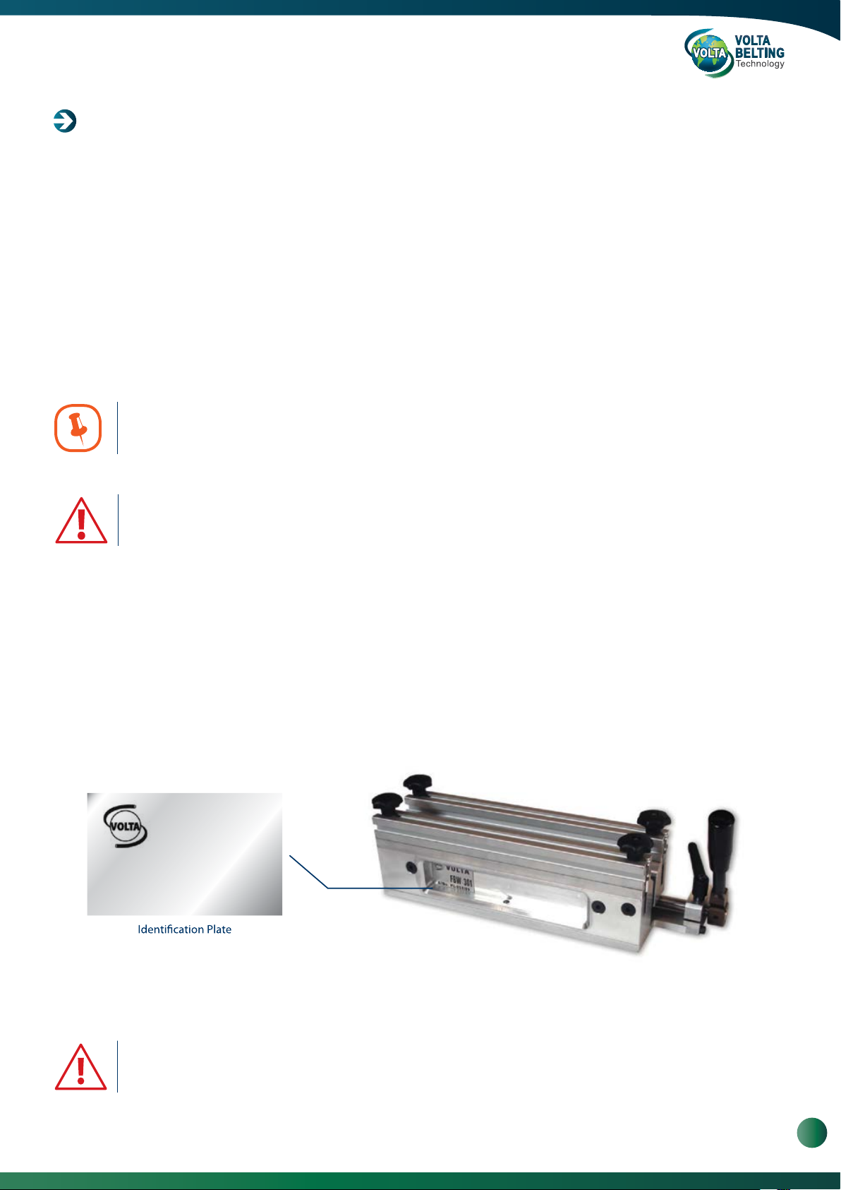
Identification Data
The identification plate is on the front of the clamp. You should include the model and serial number in all inquiries to
Volta Belting about this tool.
VOLTA
FBW 301
S/No. PL. 067/09
Example
Important: the identification plate should never be removed.
The data on the plate should not be modified.
www.voltabelting.com
3

Welding & Fabrication Tools FBW-Flat Butt Welding System Model II
1. Introduction
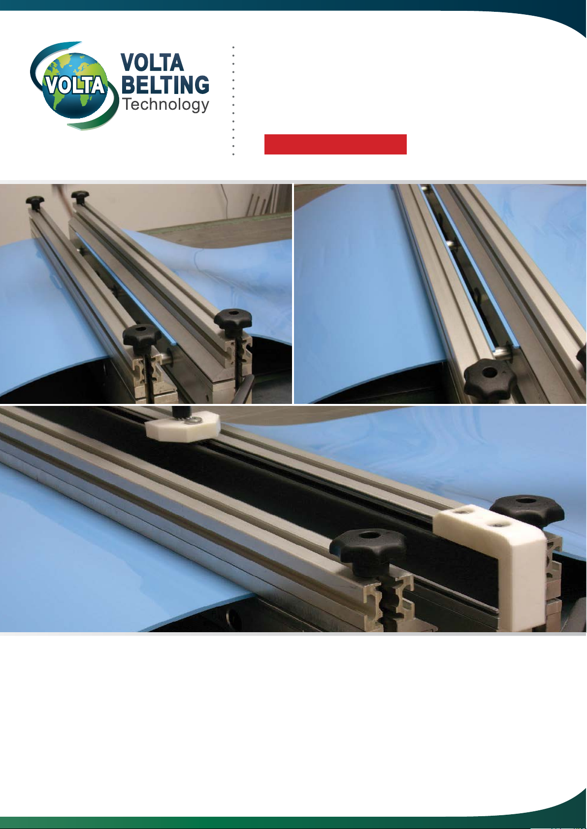
The FBW Welding Kit is designed to splice Volta
flat conveyor belts of up to 2300mm/ 90" wide.
FBW Welding Kit
The FBW Welding Kit is available in a variety of sizes and voltage/power ratings. The model number indicates
the width of belt that may be welded on a 90° joint. For example, the Model FBW 301 welds a 300mm (12”) wide belt
and the model FBW 1301 welds a belt that is 1300mm (51”) wide.
Qty. Description FBW Standard Welding Kit Components
No.
1 Case for FBW
1
2
1 Pliers
3
1 Welding Accessories (Welder, Control Box - Shinko)
4
1 SD Cutting Bar
5
1 Locator Bar
6
1 V Trim knife
1 Temperature Controller Instructions
1 FBW Welding Instructions Manual
3
4
5
2
3
6
FBW Case see picture at the top of the page
Models 301, 721, 1061 and 1301 may be operated by one person. The FBW 1701, 2101 and 2301require two
operators for correct and safe operation because of the length and weight of the Welder. The FBW Welding Kit is
supplied in a storage case to store the system components. Store only the FBW Welding components in this box to
avoid damage of the items.
Qty. Description FBW Positive Drive (PD &Mini) Welding Kit Components
No.
1 1
2 1
3 1
4 1
5 1
6 1
7 2
8
9102 Stopper for the DD /DDSP
Welding Accessories (Welder, Control Box - Shinko)
2 PD1” Adapter Set
1 Temperature Controller Instructions
1
2
FBW Welding Instructions Manual
Case for FBW
Pliers
SD Cutting Bar
Locator Bar
V Trim knife
DD Adapter
Positioner for welder*
10
2
3
4
5
7
8
3
9
6
Note: Positioner for welder* available in the FBW-1301 and FBW-1701 PD & Mini welding kits only.
FBW Case see picture at the top of the page
4
Volta Belting Technology Ltd.
2. Technical Specifications
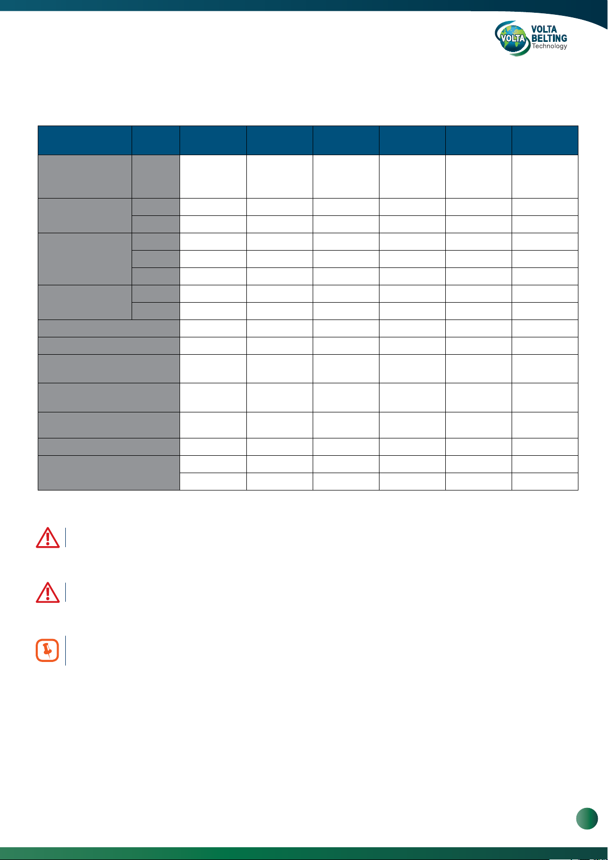
Table 1: FBW Welder System Specifications
FBW
301
110 / 230 V
Electricity
Maximum Current
Fuse
AC plug
Pliers Weight lb/ kg 13 / 6 35 /16 48 / 22 82 / 37 106 / 48* 121 / 55*
Total Weight lb/ kg 22 / 10 70 / 32* 92 / 42* 181 / 82** 225 / 102** 255 / 116**
Max. Belt Width at 90° in/ mm 24 / 300 28 / 720 41.7 / 1060 51 / 1300 66.9 / 1700 82.5 / 2100
Max. Belt Width at 45° in/ mm 6 / 150 15.7 / 400 24.4 / 620 33 / 845 45.7 / 1160 56 / 1420
Belt Thickness: in/ mm
Preheating in minutes 15 15 15 15 15 15
110 VAC 3.7 amps 7.3 amps 10 amps 12 amps N/A N/A
230 VAC 1.8 amps 3.6 amps 5 amps 5.9 amps 7.4 amps 8.7 amps
Type slow-blow slow-blow slow-blow slow-blow slow-blow slow-blow
110 VAC 10 amp 10 amps 15 amps 15 amps N/A N/A
230 VAC 10 amp 10 amps 10 amps 10 amps 10 amps 15 amps
110 VAC yes yes yes yes N/A N/A
230 VAC yes yes yes yes yes yes
Single phase
400 W
0.06-0.2 /
1.5-5
FBW
721
110 / 230 V
Single phase
800 W
0.06-0.2 /
1.5-5
FBW
1061
110 / 230 V
Single phase
1100 W
0.06-0.2 /
1.5-5
FBW
1301
110/ 230 VAC
Single phase
1300 W
0.06-0.2 /
1.5-5
FBW
1701
230 VAC
Single phase
1700 W
0.06-0.2 /
1.5-5
FBW
2101
230 VAC
Single phase
2000 W
0.06-0.2 /
1.5-5
Working Temperature
428 - 518°F 428 - 518°F 428 - 518°F 428 - 518°F 428 - 518°F 428 - 518°F
220 - 250°C 220 - 250°C 220 - 250°C 220 - 250°C 220 - 250°C 220 - 250°C
* This equipment is heavy and must be carried by two persons.
** This equipment is heavy and must be carried by a forklift.
In the USA, units are supplied with a 110 VAC North American Standard plug. In Europe, units are supplied
with a 230V German standard plug. Users must adapt the plug to the local electrical standards. This must be done
by a certified electrician and in compliance with local electrical codes and standards.
www.voltabelting.com
5
Welding & Fabrication Tools FBW-Flat Butt Welding System Model II
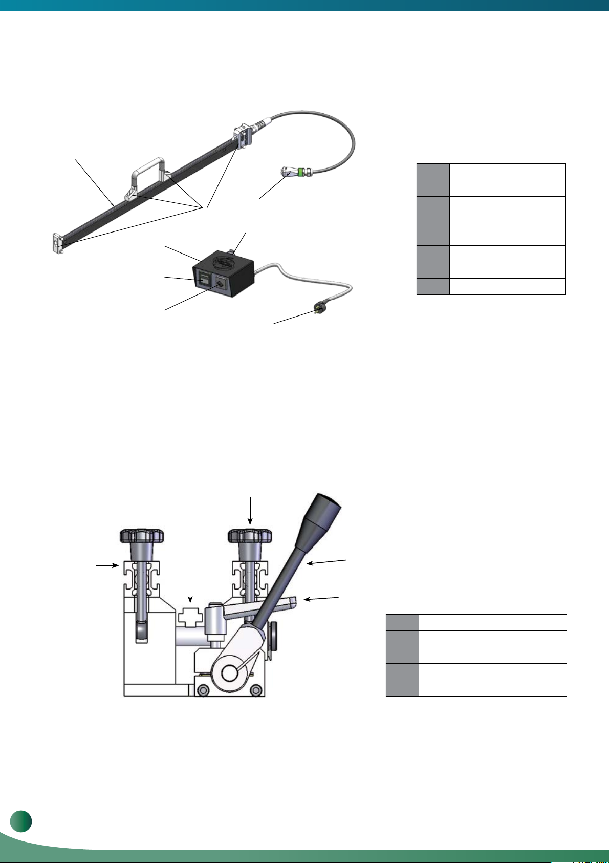
2.1. FBW Layout
1
8
2
7
3
4
5
6
1
Welder
2
Isolation Pad
3
Control Box (Shinko)
4
Temperature Control
5
Main Switch
6
Main Power
7
Output
8
Welder Input Plug
Figure 3: FBW Welder and Temperature Controller - Shinko
3
1
2
5
4
1
Crossbar
2
Locator Bar
3
Knob
4
Adjustable Lever
5
Operating Handle
6
Volta Belting Technology Ltd.
Figure 4: FBW Pliers

2.2. The Storage Case
The storage case is meant to protect the tools against dirt and damage during transportation. The case is designed to
store the entire FBW system. Tools and other items that do not belong to the FBW Welding System should not be
placed in the storage case. Loose, unsecured items may move around and damage the Teflon coating of the Welder.
Do not store chemicals in the FBW storage case - chemical fumes and possible spills may damage the wiring and
internal components
of the Controller.
2.3. The Electrical System
All metal parts of the FBW Welding System are grounded. Ensure that the electrical plug is connected to a power
source with an earth ground and a Residual-current device (RCD). The thermo-couple wires must not be disconnected
as this will cause uncontrolled heating and damage the Welder.
Electrical Shock Hazard - Never remove the ground from the power cord or
internal wiring.
2.4. Care and Maintenance
Keep the system dry and clean.
Occasionally apply a light coating of oil to sliding metal parts.
The quality of the finished weld is affected by the condition of the Welder. To obtain the highest quality results from your
Welder, always wipe the Welder’s flat surfaces with a clean cotton cloth to remove material and dirt immediately after welding.
When welding is completed, return the tools to their storage box. There is no need to wait for the Welder to fully cool
down. The partitions inside the box will ensure that the system does not move during transportation and guarantee the
tool’s long lasting functioning.
The Welder must be cleaned while hot. Because the temperature of the welder
is high, extra care must be taken to avoid burns. It is recommended that you
wear protective gloves.
www.voltabelting.com
7

Welding & Fabrication Tools FBW-Flat Butt Welding System Model II
2.5. Safety Precautions
Volta Belting accepts no liability for use of this tool in a manner other than that specified in this manual.
Volta Belting accepts no responsibility for unauthorized modifications performed on this tool.
This Instruction Manual and the warnings contained herein must be read carefully and kept clearly visible
in the vicinity of the FBW Welding Tool.
Failure to pay attention to these warnings can lead to accidents, injuries or damage to health.
2.6. Warning Notice for Welding Tools
1. Always use the original storage box to keep the welding tool when not in use. Always store tools in a
dry and secure environment.
2. Select and use the most appropriate welding tool for your application. The selection is based on
material dimensions.
3. Use the welding tool only at its rated voltage (See Table 1 - FBW Welder System Specifications).
4. Ensure that the unit is connected to an earth grounded power source. Failure to comply with this
requirement can cause electrical shock.
5. Do not use the welding tool in a damp or wet environment.
6. Do not carry the welder by its power cord or use it for unsuitable purposes.
7. Protect the cord from heat and sharp objects.
8. Do not pull on the power cord to remove the plug from its socket.
9. Always work in a well ventilated area when welding. Some materials can generate toxic fumes when
overheated.
10. Always weld on a non-combustible surface and be aware of surrounding materials. Heat may cause
fire or damage other materials.
11. Ensure that the surface of the welding bar is clean and in good condition.
12. Hold the Welder by the handles only. The Welder surface can be very hot and will cause burns.
13. If the unit requires repair, return it to Volta Belting or to your local Volta distributor.
8
Volta Belting Technology Ltd.

3. Welding Instructions
3.1. Preparing the Temperature Controller
a.
Connect the Welder to the Controller, and then connect the main power to the
power supply. Turn the Power Switch to “ON” and allow 15 minutes for the
Welder to warm up and the temperature to stabilize. The Welder is supplied
after factory adjustment and should not be altered unless there is a problem.
The Temperature Controller should be adjusted to 220°C (428°F) for all belt
types. If you need to readjust the temperature, please refer to Page 32.
3.2. Preparing the Pliers
Operating Handle
2
Cross Bar
3
1
Power Switch
Knobs (4 each)
a. Position the Pliers with the Operating Handle closest to
you.
b.
Loosen the 4 knobs securing the Crossbars. The two
knobs closest to the Operating Handle are hinged
and can be swung out and down to remove the
Crossbars.
c.
Remove the Crossbars and set them aside. FBW
models 1301, 1701 & 2101 are equipped with magnetic
crossbars. To remove these crossbars, slide or roll
them off the Pliers.
Apply strips of good quality double-sided tape on the
d.
upper surfaces of the Pliers’ jaws.
54
e.
Position the Locator Bar between the jaws of the
Pliers. Place the Locator Bar in the center of the
Pliers and over the Pliers Shafts. The belt locator has
reference marks for belt alignment, Each side of the
Belt Locator Bar has notes for different belt
thicknesses. One side is marked for 1.5 to 2.5 mm
belts and the opposite side for 3 to 5 mm belts.
Ensure that you have the correct side facing up.
f.
Move the Operating Handle to close the Pliers jaws
and lock in place using the Locking Lever. (By pulling
the lever up you can adjust the handle position).
www.voltabelting.com
9
Welding & Fabrication Tools FBW-Flat Butt Welding System Model II
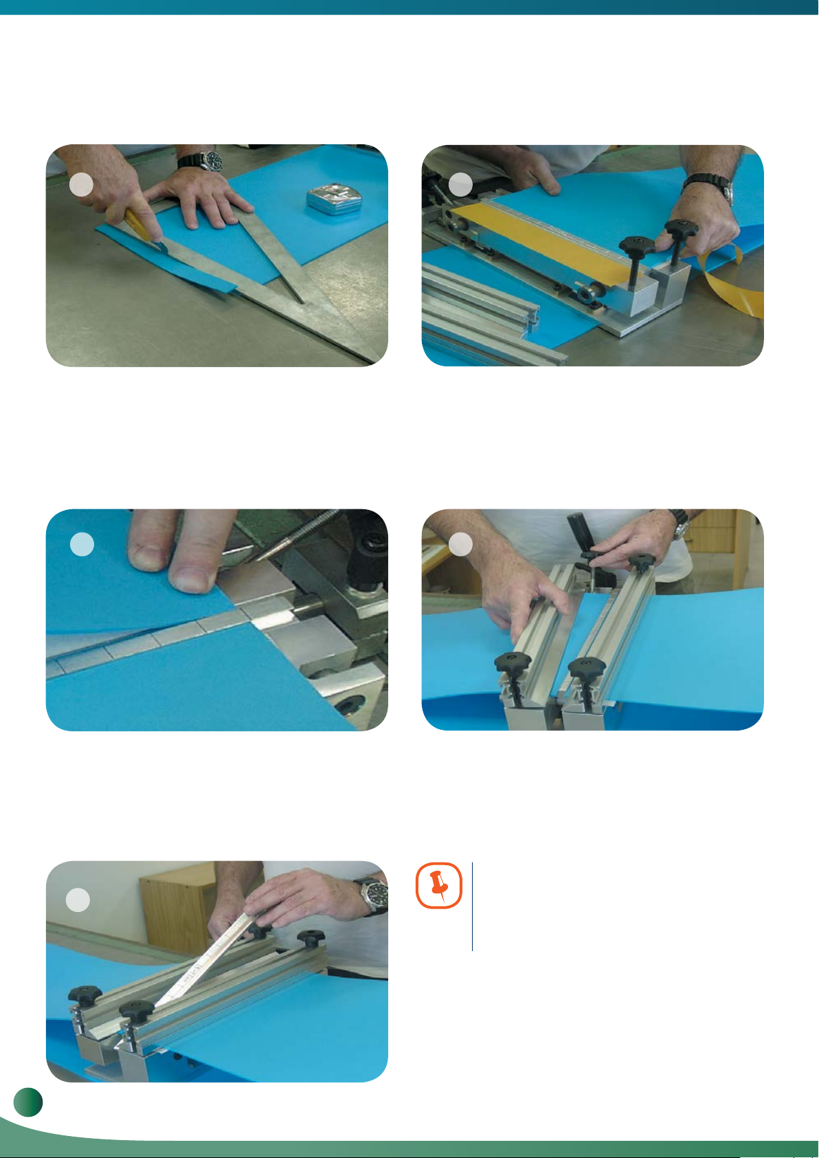
3.3. Preparing the Belt
6
Cut the two ends of the belt at 90°. Ensure that the
a.
cut is accurate and straight.
b.
Clean the belt ends with denatured alcohol. The
belt ends must be free of dirt and grease in order to
ensure a consistent, high quality weld.
8
7
c.
Remove the protective paper from one piece of the
doublesided tape and place one end of the belt against
the Locator Bar in line with a reference mark. Press the
belt onto the tape to ensure good adhesion. There
should be no gaps between the belt edge and the
Locator Bar. Gaps will produce an inconsistent weld
and lead to early failure of the weld.
9
Repeat this procedure for the opposite belt end. Make
d.
sure you align the edge of the belt with the reference
mark on the Locator Bar, to ensure a straight edge
between the two ends of the belt.
10
10
Volta Belting Technology Ltd.
Set the Crossbars in place and swing the Locking Bolt
e.
into position. Finger tighten the nuts. Be careful to
apply even pressure on Crossbars. Uneven pressure
will allow the belt to shift during welding and too much
pressure will cause the Crossbars to bend.
Note: If the belt is narrow in comparison
to the tool, add belt pieces to each side
of the belt to fill the gap. This will prevent
bending of the crossbar.
Open the Pliers and remove the Locator Bar. Leave the
f.
Pliers open The system is now ready for welding.

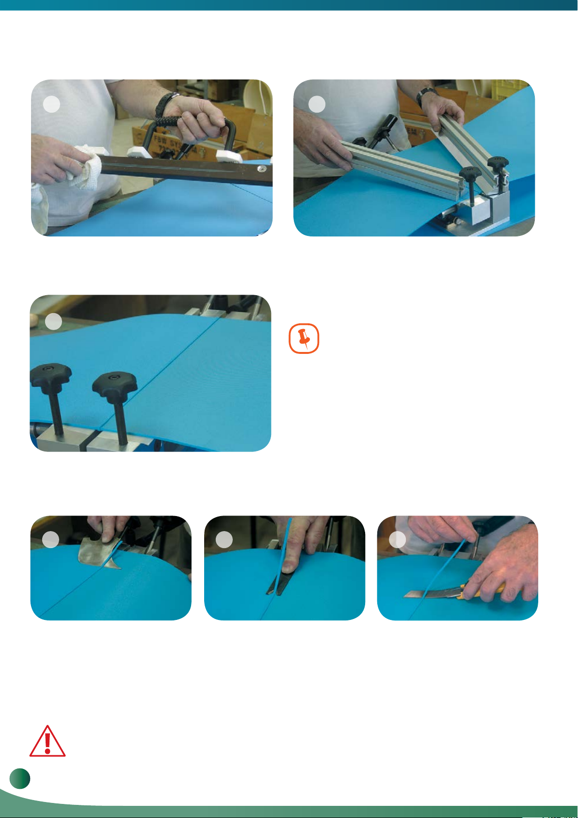
3.4. Welding the Belt
a. b.
Clean the belt and Welder. With the Welder cable
away from the operator, place the pre-heated Welder
between the two edges of the belt. Position the
Welder over the Pliers guide bars.
1211
Using the Operating Handle bring the two belt ends into
contact with the Welder. Apply very gentle pressure
and observe the melting of the material along both
sides of the Welder. Do not hold the Welder during the
welding process. The Welder should be free to move
with the belt. When the material is evenly melted along
the length of both sides of the Welder, move the
Operating Handle to open the Pliers. Quickly remove
the Welder and close the Pliers. This operation should
be performed quickly but without too much force.
13
c.
With the belt ends pressed together, lock the Adjusting
Lever. The weld requires approximately 5 minutes to
cool. The time required for cooling depends on the
thickness of the belt and the ambient temperature.
When removing the Welder, pull it straight up in a quick
movement. This will prevent the welder from pulling
melted material off of the belt ends.
14
d.
The cooling process can be sped up by directing
compressed air along the weld.
Amount of excess when belt ends
are properly melted.
www.voltabelting.com
11
Welding & Fabrication Tools FBW-Flat Butt Welding System Model II
15 16
e.
Clean the Welder using a clean, dry, lint-free soft Cotton
cloth while the Welder is hot. Leaving material on the
Welder will damage the Welders surface and reduce the
efficiency of the Welder and the quality of the welds.
f. When the belt is cooled, leave the Pliers closed and
remove the two Crossbars.
17
The following factors must be kept in mind
when welding:
•
The amount of pressure required to secure the ends of the
belt depends on the thickness and type of material being
welded.
During welding, air bubbles are formed in the melted ends.
•
The bubbles should be pressed out during the operation.
If too much pressure is applied during welding, the heat will
•
penetrate only a very narrow section along the edge of the
g. Welded belt with excess.
3.5. Trimming and Checking the Weld
Using a Leister Knife or other appropriate tool, trim the excess from the top of the belt.
a.
18 19 20
belt. When the Pliers are closed this small amount of melted
material will be pushed out. To ensure a quality weld, the
heat must penetrate a wide section of the belt.
Using Leister Knife to trim
excess from weld
b.
Separate the belt from the Pliers and turn it over placing
the trimmed surface on the Pliers. Trim the excess from
the bottom of the belt.
Use a finger guard when engaging in various activities that involve the use
of sharp objects. Handle the knife with care. Cut away from your body, not toward it.
12
Volta Belting Technology Ltd.
Using V-trimmer to trim
excess from weld
c.
Check the splice quality by bending the belt in both
directions. Check the quality of the splice across the
width of the belt and on both sides. A good weld will be
free of cracks and defects. In case of a bad splice repeat
the above steps (this will cause the loss of about 5 mm
of the belt’s length).
Using Utility knife to trim
excess from weld
 Loading...