

Welding & Fabrication Tools
FBW-Flat Butt Welding
System - Model II
Instruction Manual
The Next Step in Belting

Table of Contents
Page
How to use this manual
Symbols used in this manual
1. Introduction
2. Technical Specifications
2.1. FBW (Flat Butt Welding System Model II) Layout
2.2. The Storage Case
2.3. The Electrical System
2.4. Care and Maintenance
2.5. Safety Precautions
2.6. Warning Notice for Welding Tools
3. Welding Instruction
3.1. Preparing the Temperature Controller
3.2. Preparing the Pliers
3.3. Preparing the Belt
3
3
3
4
5
6
7
7
7
8
8
9
9
9
10
3.4. Welding the Belt
3.5. Trimming and Checking the Weld
4.
Welding Texture Top Belts
4.1.
Saw Tooth (IST) & Nub Top (NT)
4.2.
MiniCleat (MC)
4.3.
Spikes (SP)
4.4. Cresent top (CT)
5. Instructions for Splicing Reinforced Flat Belts
6. Instructions for Welding Narrow Belts
7. Instructions for Welding H Material Belts
8. Welding Positive Drive Belts
8.1. Instructions for Welding SuperDrive™ H/M Material Belts
8.2. Instructions for Welding SuperDrive™ Belts Using FBW Adapter
8.3. Positioner for Welder
8.4. Welding DualDrive
8.5. Welding Mini SuperDrive™ and Mini DualDrive™ Belts
TM
Belts
11
12
13
13
14
15
17
18
19
19
20
20
22
22
23
25
8.6. Welding Mini SuperDrive™ MiniCleat Belt
8.7. Welding DualDrive™ SP (DDSP) Belts and DDSP Lace
8.8. Welding Volta Hinge Lace
9. General Tips
10. Troubleshooting Guide
11. FBW System Model II Shinko Controller and Welder Electrical Diagram
12. Calibrating the FBW Welder System Model II Shinko Controller
13. Pitch Gauge Measuring Tool for the Positive Drive Belts
27
29
31
33
33
34
35
37
Thank you for buying the Volta FBW Welding Kit. If you have any questions about the use of this
tool please contact our Technical Service Department at email: sales@voltabelting.com or visit our
website www.voltabelting.com.
How to Use this Manual
This manual has been designed to provide the operator with all the necessary information on how to use the above tool
correctly. Warnings in the manual should be carefully followed for your personal safety. Be sure you carefully read the
instructions in this manual before using the tool. This will ensure use in compliance with safety standards.
Symbols Used in the Manual
This symbol is used for important Notes & Tips
This symbol is used to warn you of actions that are dangerous for the operator.
Read the associated warnings and instructions carefully.
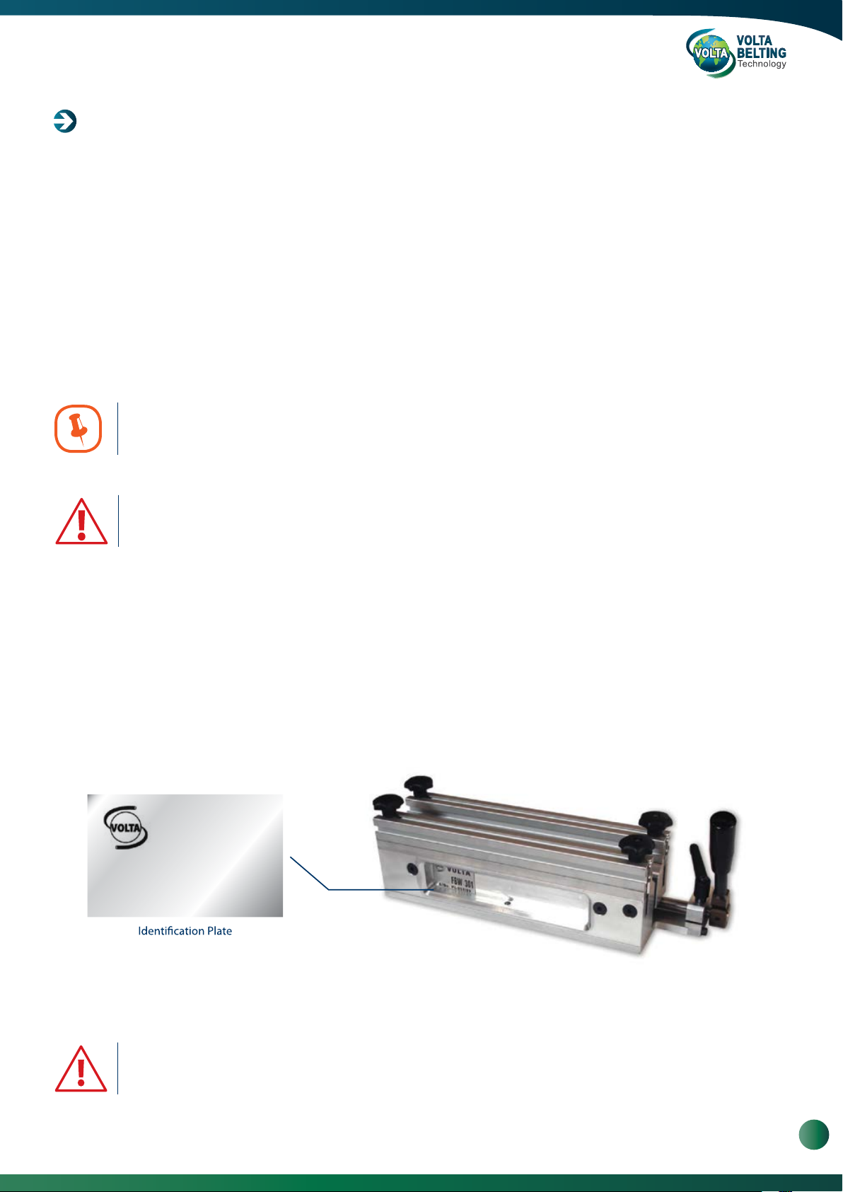
Identification Data
The identification plate is on the front of the clamp. You should include the model and serial number in all inquiries to
Volta Belting about this tool.
VOLTA
FBW 301
S/No. PL. 067/09
Example
Important: the identification plate should never be removed.
The data on the plate should not be modified.
www.voltabelting.com
3

Welding & Fabrication Tools FBW-Flat Butt Welding System Model II
1. Introduction
The FBW Welding Kit is designed to splice Volta
flat conveyor belts of up to 2300mm/ 90" wide.
FBW Welding Kit
The FBW Welding Kit is available in a variety of sizes and voltage/power ratings. The model number indicates
the width of belt that may be welded on a 90° joint. For example, the Model FBW 301 welds a 300mm (12”) wide belt
and the model FBW 1301 welds a belt that is 1300mm (51”) wide.
Qty. Description FBW Standard Welding Kit Components
No.
1 Case for FBW
1
2
1 Pliers
3
1 Welding Accessories (Welder, Control Box - Shinko)
4
1 SD Cutting Bar
5
1 Locator Bar
6
1 V Trim knife
1 Temperature Controller Instructions
1 FBW Welding Instructions Manual
3
4
5
2
3
6
FBW Case see picture at the top of the page
Models 301, 721, 1061 and 1301 may be operated by one person. The FBW 1701, 2101 and 2301require two
operators for correct and safe operation because of the length and weight of the Welder. The FBW Welding Kit is
supplied in a storage case to store the system components. Store only the FBW Welding components in this box to
avoid damage of the items.
Qty. Description FBW Positive Drive (PD &Mini) Welding Kit Components
No.
1 1
2 1
3 1
4 1
5 1
6 1
7 2
8
9102 Stopper for the DD /DDSP
Welding Accessories (Welder, Control Box - Shinko)
2 PD1” Adapter Set
1 Temperature Controller Instructions
1
2
FBW Welding Instructions Manual
Case for FBW
Pliers
SD Cutting Bar
Locator Bar
V Trim knife
DD Adapter
Positioner for welder*
10
2
3
4
5
7
8
3
9
6
Note: Positioner for welder* available in the FBW-1301 and FBW-1701 PD & Mini welding kits only.
FBW Case see picture at the top of the page
4
Volta Belting Technology Ltd.
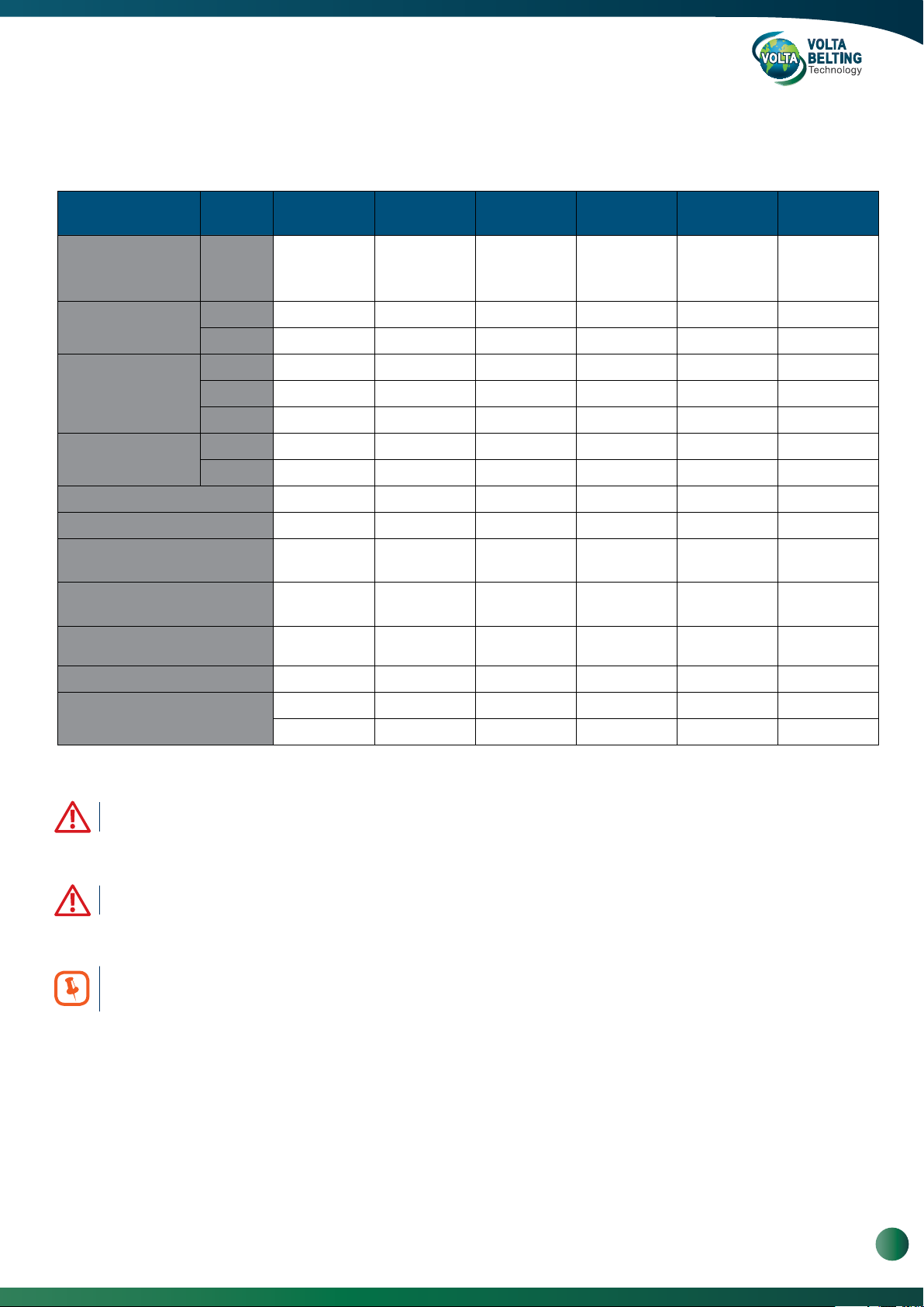
2. Technical Specifications
Table 1: FBW Welder System Specifications
FBW
301
110 / 230 V
Electricity
Maximum Current
Fuse
AC plug
Pliers Weight lb/ kg 13 / 6 35 /16 48 / 22 82 / 37 106 / 48* 121 / 55*
Total Weight lb/ kg 22 / 10 70 / 32* 92 / 42* 181 / 82** 225 / 102** 255 / 116**
Max. Belt Width at 90° in/ mm 24 / 300 28 / 720 41.7 / 1060 51 / 1300 66.9 / 1700 82.5 / 2100
Max. Belt Width at 45° in/ mm 6 / 150 15.7 / 400 24.4 / 620 33 / 845 45.7 / 1160 56 / 1420
Belt Thickness: in/ mm
Preheating in minutes 15 15 15 15 15 15
110 VAC 3.7 amps 7.3 amps 10 amps 12 amps N/A N/A
230 VAC 1.8 amps 3.6 amps 5 amps 5.9 amps 7.4 amps 8.7 amps
Type slow-blow slow-blow slow-blow slow-blow slow-blow slow-blow
110 VAC 10 amp 10 amps 15 amps 15 amps N/A N/A
230 VAC 10 amp 10 amps 10 amps 10 amps 10 amps 15 amps
110 VAC yes yes yes yes N/A N/A
230 VAC yes yes yes yes yes yes
Single phase
400 W
0.06-0.2 /
1.5-5
FBW
721
110 / 230 V
Single phase
800 W
0.06-0.2 /
1.5-5
FBW
1061
110 / 230 V
Single phase
1100 W
0.06-0.2 /
1.5-5
FBW
1301
110/ 230 VAC
Single phase
1300 W
0.06-0.2 /
1.5-5
FBW
1701
230 VAC
Single phase
1700 W
0.06-0.2 /
1.5-5
FBW
2101
230 VAC
Single phase
2000 W
0.06-0.2 /
1.5-5
Working Temperature
428 - 518°F 428 - 518°F 428 - 518°F 428 - 518°F 428 - 518°F 428 - 518°F
220 - 250°C 220 - 250°C 220 - 250°C 220 - 250°C 220 - 250°C 220 - 250°C
* This equipment is heavy and must be carried by two persons.
** This equipment is heavy and must be carried by a forklift.
In the USA, units are supplied with a 110 VAC North American Standard plug. In Europe, units are supplied
with a 230V German standard plug. Users must adapt the plug to the local electrical standards. This must be done
by a certified electrician and in compliance with local electrical codes and standards.
www.voltabelting.com
5
Welding & Fabrication Tools FBW-Flat Butt Welding System Model II
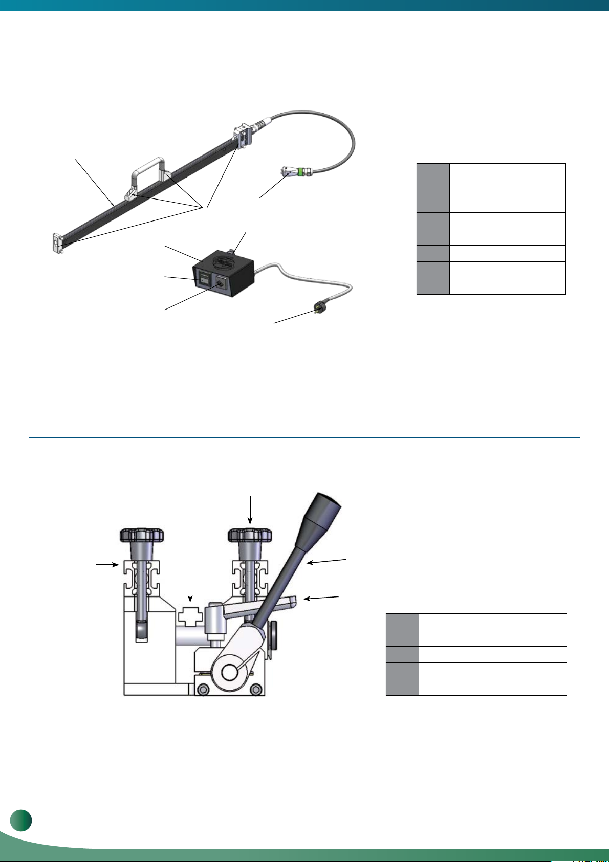
2.1. FBW Layout
1
8
2
7
3
4
5
6
1
Welder
2
Isolation Pad
3
Control Box (Shinko)
4
Temperature Control
5
Main Switch
6
Main Power
7
Output
8
Welder Input Plug
Figure 3: FBW Welder and Temperature Controller - Shinko
3
1
2
5
4
1
Crossbar
2
Locator Bar
3
Knob
4
Adjustable Lever
5
Operating Handle
6
Volta Belting Technology Ltd.
Figure 4: FBW Pliers

2.2. The Storage Case
The storage case is meant to protect the tools against dirt and damage during transportation. The case is designed to
store the entire FBW system. Tools and other items that do not belong to the FBW Welding System should not be
placed in the storage case. Loose, unsecured items may move around and damage the Teflon coating of the Welder.
Do not store chemicals in the FBW storage case - chemical fumes and possible spills may damage the wiring and
internal components
of the Controller.
2.3. The Electrical System
All metal parts of the FBW Welding System are grounded. Ensure that the electrical plug is connected to a power
source with an earth ground and a Residual-current device (RCD). The thermo-couple wires must not be disconnected
as this will cause uncontrolled heating and damage the Welder.
Electrical Shock Hazard - Never remove the ground from the power cord or
internal wiring.
2.4. Care and Maintenance
Keep the system dry and clean.
Occasionally apply a light coating of oil to sliding metal parts.
The quality of the finished weld is affected by the condition of the Welder. To obtain the highest quality results from your
Welder, always wipe the Welder’s flat surfaces with a clean cotton cloth to remove material and dirt immediately after welding.
When welding is completed, return the tools to their storage box. There is no need to wait for the Welder to fully cool
down. The partitions inside the box will ensure that the system does not move during transportation and guarantee the
tool’s long lasting functioning.
The Welder must be cleaned while hot. Because the temperature of the welder
is high, extra care must be taken to avoid burns. It is recommended that you
wear protective gloves.
www.voltabelting.com
7

Welding & Fabrication Tools FBW-Flat Butt Welding System Model II
2.5. Safety Precautions
Volta Belting accepts no liability for use of this tool in a manner other than that specified in this manual.
Volta Belting accepts no responsibility for unauthorized modifications performed on this tool.
This Instruction Manual and the warnings contained herein must be read carefully and kept clearly visible
in the vicinity of the FBW Welding Tool.
Failure to pay attention to these warnings can lead to accidents, injuries or damage to health.
2.6. Warning Notice for Welding Tools
1. Always use the original storage box to keep the welding tool when not in use. Always store tools in a
dry and secure environment.
2. Select and use the most appropriate welding tool for your application. The selection is based on
material dimensions.
3. Use the welding tool only at its rated voltage (See Table 1 - FBW Welder System Specifications).
4. Ensure that the unit is connected to an earth grounded power source. Failure to comply with this
requirement can cause electrical shock.
5. Do not use the welding tool in a damp or wet environment.
6. Do not carry the welder by its power cord or use it for unsuitable purposes.
7. Protect the cord from heat and sharp objects.
8. Do not pull on the power cord to remove the plug from its socket.
9. Always work in a well ventilated area when welding. Some materials can generate toxic fumes when
overheated.
10. Always weld on a non-combustible surface and be aware of surrounding materials. Heat may cause
fire or damage other materials.
11. Ensure that the surface of the welding bar is clean and in good condition.
12. Hold the Welder by the handles only. The Welder surface can be very hot and will cause burns.
13. If the unit requires repair, return it to Volta Belting or to your local Volta distributor.
8
Volta Belting Technology Ltd.

3. Welding Instructions
3.1. Preparing the Temperature Controller
a.
Connect the Welder to the Controller, and then connect the main power to the
power supply. Turn the Power Switch to “ON” and allow 15 minutes for the
Welder to warm up and the temperature to stabilize. The Welder is supplied
after factory adjustment and should not be altered unless there is a problem.
The Temperature Controller should be adjusted to 220°C (428°F) for all belt
types. If you need to readjust the temperature, please refer to Page 32.
3.2. Preparing the Pliers
Operating Handle
2
Cross Bar
3
1
Power Switch
Knobs (4 each)
a. Position the Pliers with the Operating Handle closest to
you.
b.
Loosen the 4 knobs securing the Crossbars. The two
knobs closest to the Operating Handle are hinged
and can be swung out and down to remove the
Crossbars.
c.
Remove the Crossbars and set them aside. FBW
models 1301, 1701 & 2101 are equipped with magnetic
crossbars. To remove these crossbars, slide or roll
them off the Pliers.
Apply strips of good quality double-sided tape on the
d.
upper surfaces of the Pliers’ jaws.
54
e.
Position the Locator Bar between the jaws of the
Pliers. Place the Locator Bar in the center of the
Pliers and over the Pliers Shafts. The belt locator has
reference marks for belt alignment, Each side of the
Belt Locator Bar has notes for different belt
thicknesses. One side is marked for 1.5 to 2.5 mm
belts and the opposite side for 3 to 5 mm belts.
Ensure that you have the correct side facing up.
f.
Move the Operating Handle to close the Pliers jaws
and lock in place using the Locking Lever. (By pulling
the lever up you can adjust the handle position).
www.voltabelting.com
9
Welding & Fabrication Tools FBW-Flat Butt Welding System Model II
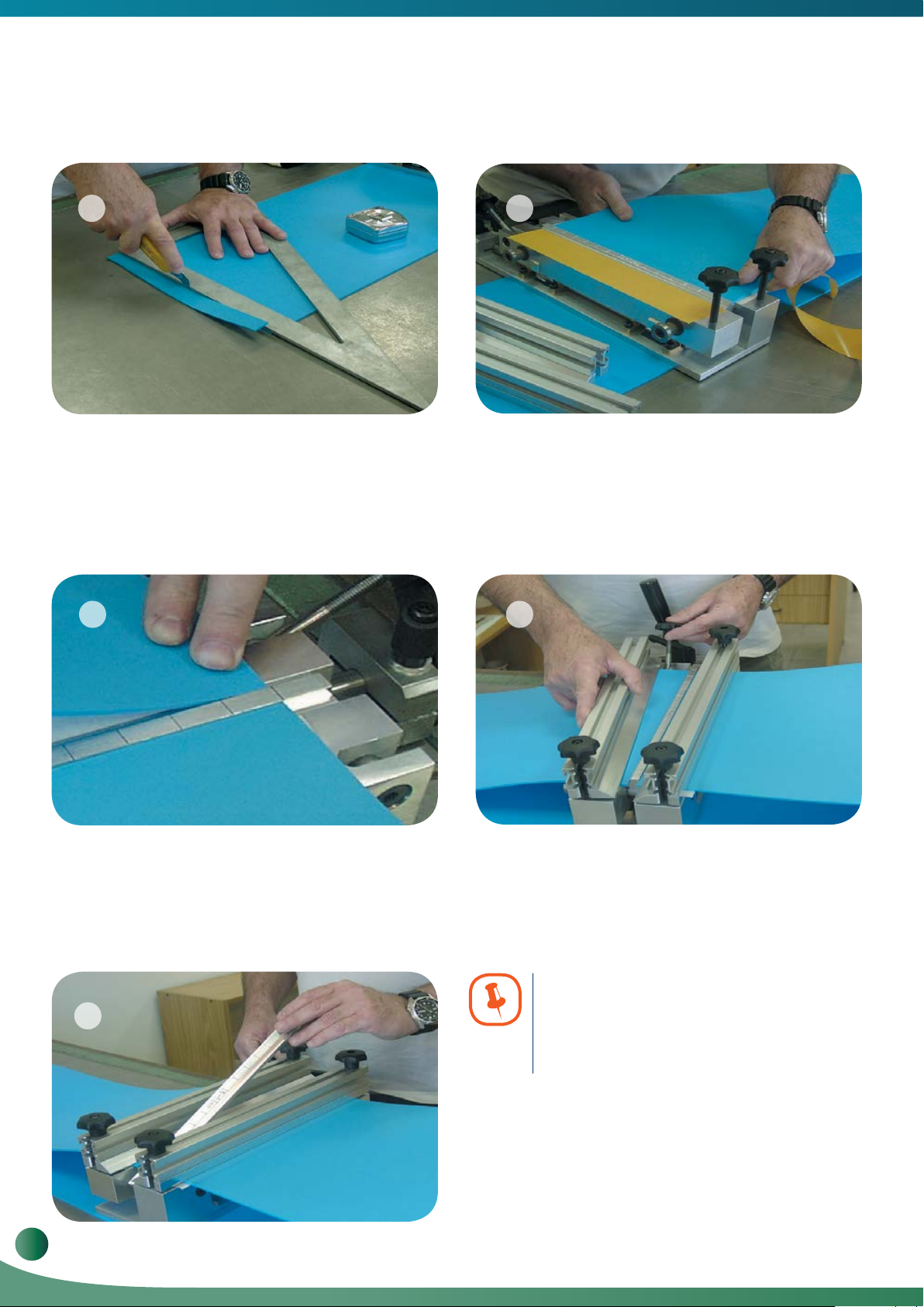
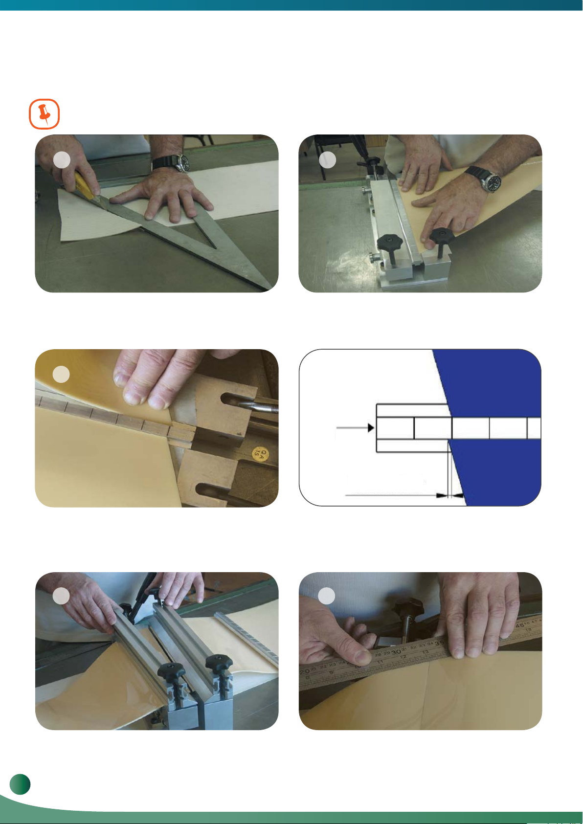
3.3. Preparing the Belt
6
Cut the two ends of the belt at 90°. Ensure that the
a.
cut is accurate and straight.
b.
Clean the belt ends with denatured alcohol. The
belt ends must be free of dirt and grease in order to
ensure a consistent, high quality weld.
8
7
c.
Remove the protective paper from one piece of the
doublesided tape and place one end of the belt against
the Locator Bar in line with a reference mark. Press the
belt onto the tape to ensure good adhesion. There
should be no gaps between the belt edge and the
Locator Bar. Gaps will produce an inconsistent weld
and lead to early failure of the weld.
9
Repeat this procedure for the opposite belt end. Make
d.
sure you align the edge of the belt with the reference
mark on the Locator Bar, to ensure a straight edge
between the two ends of the belt.
10
10
Volta Belting Technology Ltd.
Set the Crossbars in place and swing the Locking Bolt
e.
into position. Finger tighten the nuts. Be careful to
apply even pressure on Crossbars. Uneven pressure
will allow the belt to shift during welding and too much
pressure will cause the Crossbars to bend.
Note: If the belt is narrow in comparison
to the tool, add belt pieces to each side
of the belt to fill the gap. This will prevent
bending of the crossbar.
Open the Pliers and remove the Locator Bar. Leave the
f.
Pliers open The system is now ready for welding.

3.4. Welding the Belt
a. b.
Clean the belt and Welder. With the Welder cable
away from the operator, place the pre-heated Welder
between the two edges of the belt. Position the
Welder over the Pliers guide bars.
1211
Using the Operating Handle bring the two belt ends into
contact with the Welder. Apply very gentle pressure
and observe the melting of the material along both
sides of the Welder. Do not hold the Welder during the
welding process. The Welder should be free to move
with the belt. When the material is evenly melted along
the length of both sides of the Welder, move the
Operating Handle to open the Pliers. Quickly remove
the Welder and close the Pliers. This operation should
be performed quickly but without too much force.
13
c.
With the belt ends pressed together, lock the Adjusting
Lever. The weld requires approximately 5 minutes to
cool. The time required for cooling depends on the
thickness of the belt and the ambient temperature.
When removing the Welder, pull it straight up in a quick
movement. This will prevent the welder from pulling
melted material off of the belt ends.
14
d.
The cooling process can be sped up by directing
compressed air along the weld.
Amount of excess when belt ends
are properly melted.
www.voltabelting.com
11
Welding & Fabrication Tools FBW-Flat Butt Welding System Model II
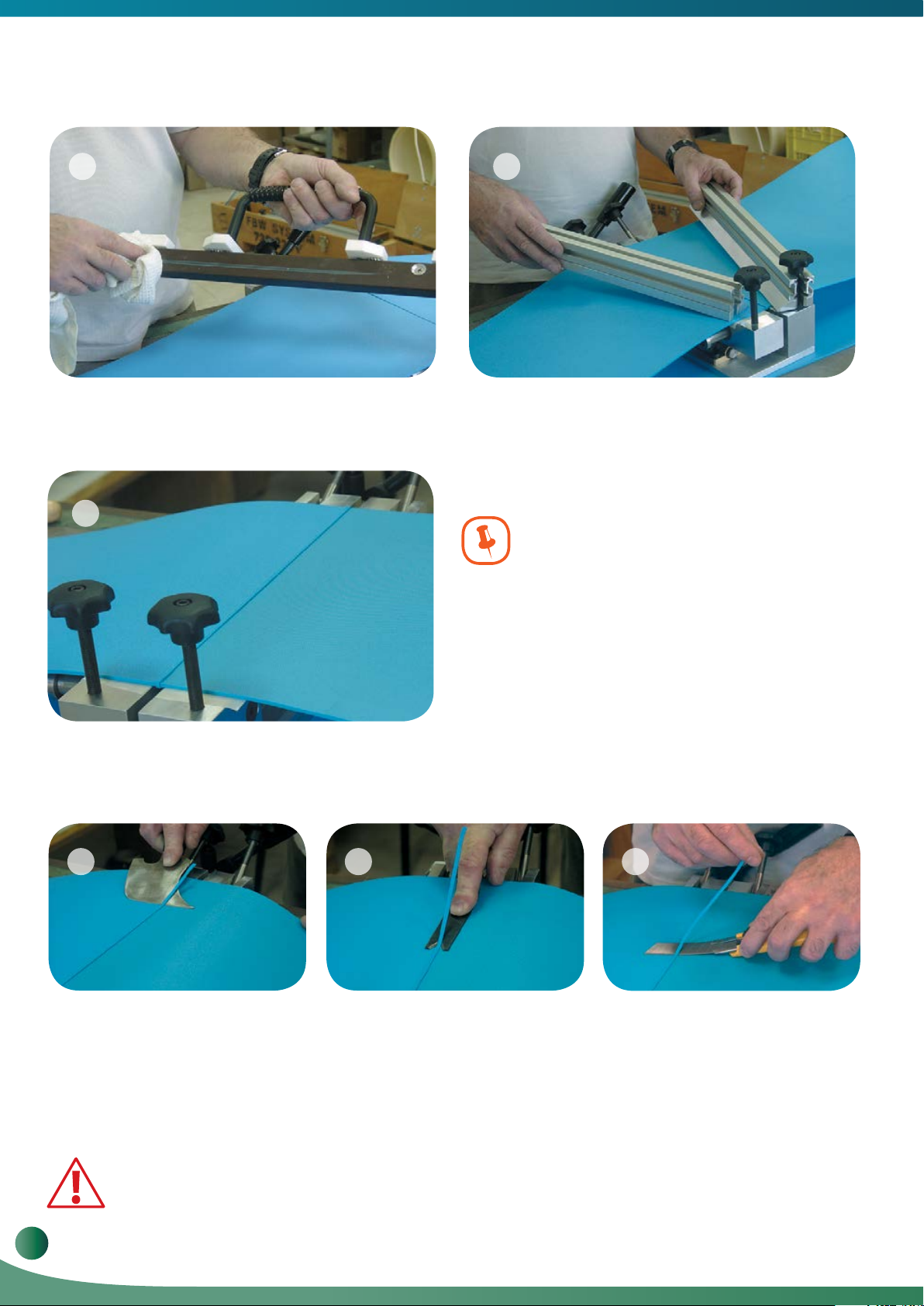
15 16
e.
Clean the Welder using a clean, dry, lint-free soft Cotton
cloth while the Welder is hot. Leaving material on the
Welder will damage the Welders surface and reduce the
efficiency of the Welder and the quality of the welds.
f. When the belt is cooled, leave the Pliers closed and
remove the two Crossbars.
17
The following factors must be kept in mind
when welding:
•
The amount of pressure required to secure the ends of the
belt depends on the thickness and type of material being
welded.
During welding, air bubbles are formed in the melted ends.
•
The bubbles should be pressed out during the operation.
If too much pressure is applied during welding, the heat will
•
penetrate only a very narrow section along the edge of the
g. Welded belt with excess.
3.5. Trimming and Checking the Weld
Using a Leister Knife or other appropriate tool, trim the excess from the top of the belt.
a.
18 19 20
belt. When the Pliers are closed this small amount of melted
material will be pushed out. To ensure a quality weld, the
heat must penetrate a wide section of the belt.
Using Leister Knife to trim
excess from weld
b.
Separate the belt from the Pliers and turn it over placing
the trimmed surface on the Pliers. Trim the excess from
the bottom of the belt.
Use a finger guard when engaging in various activities that involve the use
of sharp objects. Handle the knife with care. Cut away from your body, not toward it.
12
Volta Belting Technology Ltd.
Using V-trimmer to trim
excess from weld
c.
Check the splice quality by bending the belt in both
directions. Check the quality of the splice across the
width of the belt and on both sides. A good weld will be
free of cracks and defects. In case of a bad splice repeat
the above steps (this will cause the loss of about 5 mm
of the belt’s length).
Using Utility knife to trim
excess from weld

4. Welding Texture Top Belts
4.1 Saw Tooth (IST) & Nub Top (NT)
For welding these textured top belts IST-Saw Tooth and NT-Nub Top use the same adaptor as for the flat belts.
No special adaptors required.
If you haven’t welded this product before, weld a section of a trial belt before welding your Volta conveyor belt.
Follow the instructions from Page 9 to prepare the Temperature Controller and the Pliers.
1. Welding IST-Impression Saw Tooth Belt
1 2
Cut the two ends of the belt at 90o following the instructions from the sketch below:
Center line of IST
&HQWHUOLQHRI,67
/HIWVLGH&HQWHUOLQHPP
Left side: Center line +1mm
Right side: Center line +1mm
5LJKWVLGH&HQWHUOLQHPP
2. Welding NT-Nub Top Belt
3 4
Position both sides of the belt on the Pliers
•
with the belts’ pattern facing up.
Weld the belt according to the FBW
•
Instructions Manual Page 10-12.
Trim out 1 row of Nub Top Texture on all the
width of the belt from both sides :
Cut the belt un the middle of the trimmed
•
Nub Top area at 90
Position both sides of the belt on the Pliers
•
with the belts’ pattern facing up.
Weld the belt according to the FBW
•
Instructions Manual Page 10-12.
o
.
www.voltabelting.com
13

Welding & Fabrication Tools FBW-Flat Butt Welding System Model II
4.2. Welding MiniCleat (MC)
Required Tools:
FBW Welding Kit
MC Adapter Set for FBW - 301 Cat. #813072510
MC Adapter Set for FBW - 721 Cat. #81307241
MC Adapter Set for FBW - 1061 Cat. #81310601
MC Adapter Set for FBW - 1301* Cat. #81313008
Positioner for welder** Cat.#81626342
V Trim Knife Cat. #8153108
Utility Knife
* Non-standard
** Positioner for welder FBW - 1301 and FBW - 1701 only.
Instructions on Page 22.
You must be familiar with the instructions for welding with FBW before continuing
with this procedure.
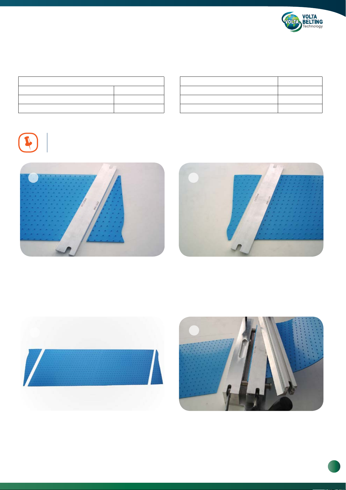
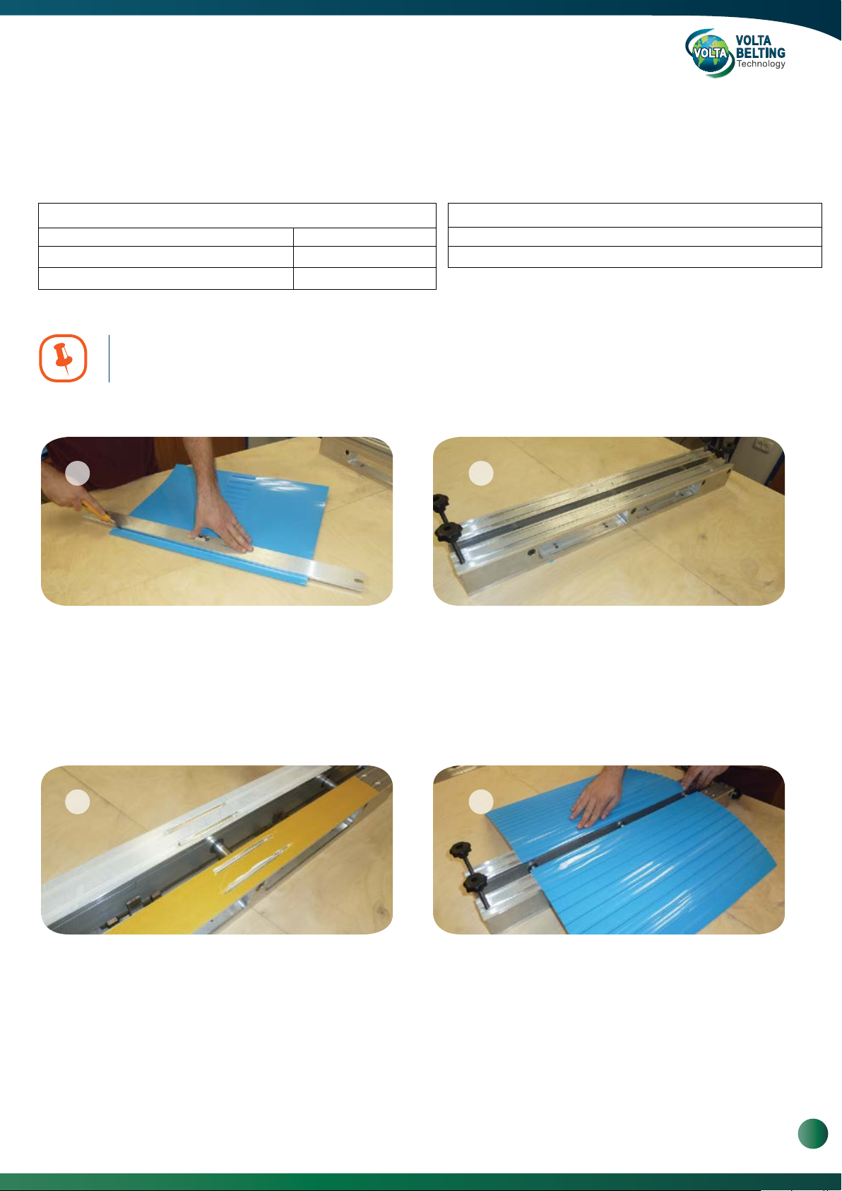
1 2
To ensure correct position on the pliers and right pitch of
thepattern, place the adapter on the belt and cut the two
ends of the belt along the “Cutting” side of the Adapter.
3
Position and then tighten the FBW Crossbars. Weld the
belt according to the FBW Instructions Manual.
Position both sides of the belt on the Pliers with the belts’
patten facing up. Position the Adapters onto the Belt.
Align the belt patten to the Adapter grooves.
4
Trim and check the weld. A good weld will be free of cracks
and defects.
14
Volta Belting Technology Ltd.
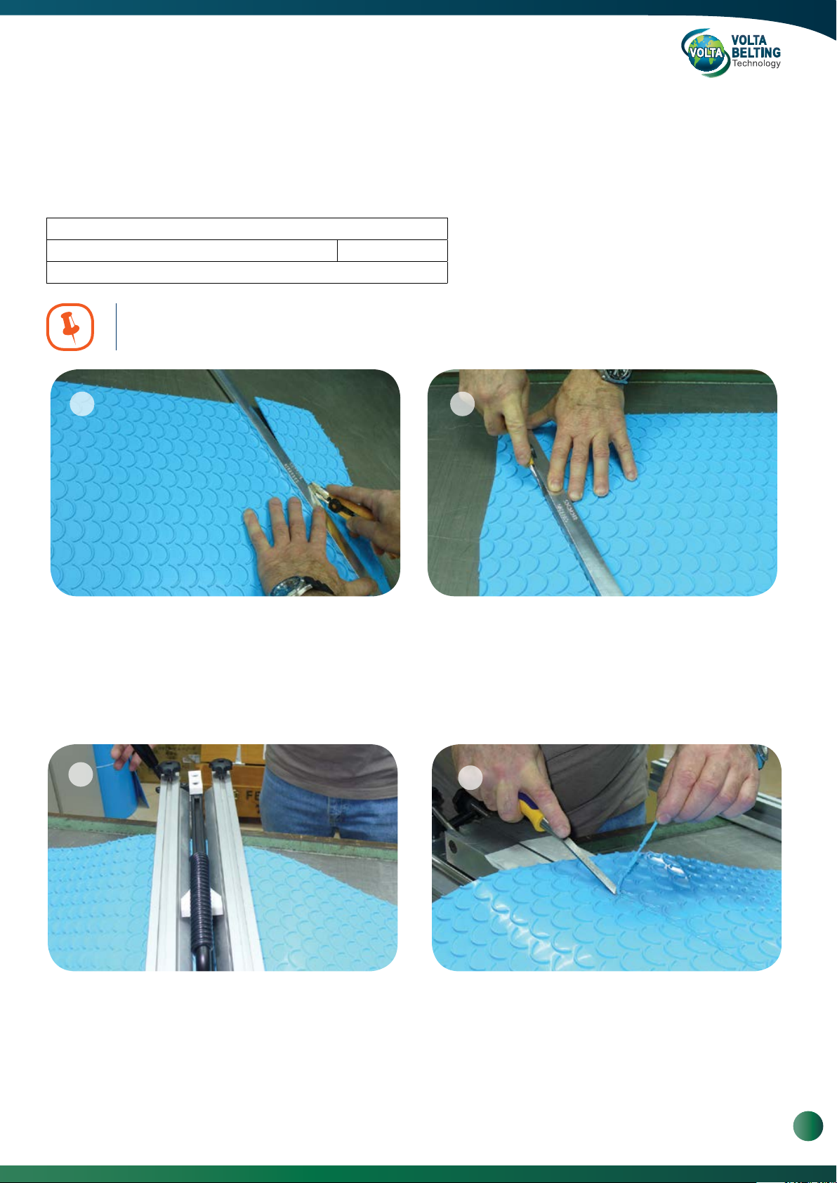
4.3. Welding Volta Spikes (SP)
21
Required Tools:
FBW Welding Kit
Spikes Adapter Set for FBW - 301 Cat. #813072535
Spikes Adapter Set for FBW - 721 Cat. #81307248
Spikes Adapter Set for FBW - 1061 Cat. #81310608
You must be familiar with the instructions for welding with FBW before continuing
with this procedure.
1 2
Spikes Adapter Set for FBW - 1301* Cat. #81313011
Positioner for welder** Cat. #81626342
V Trim Knife Narrow Cat. #8153108
Utility Knife
* Non-standard
** Positioner for welder FBW - 1301 and FBW - 1701 only.
Instructions on Page 22.
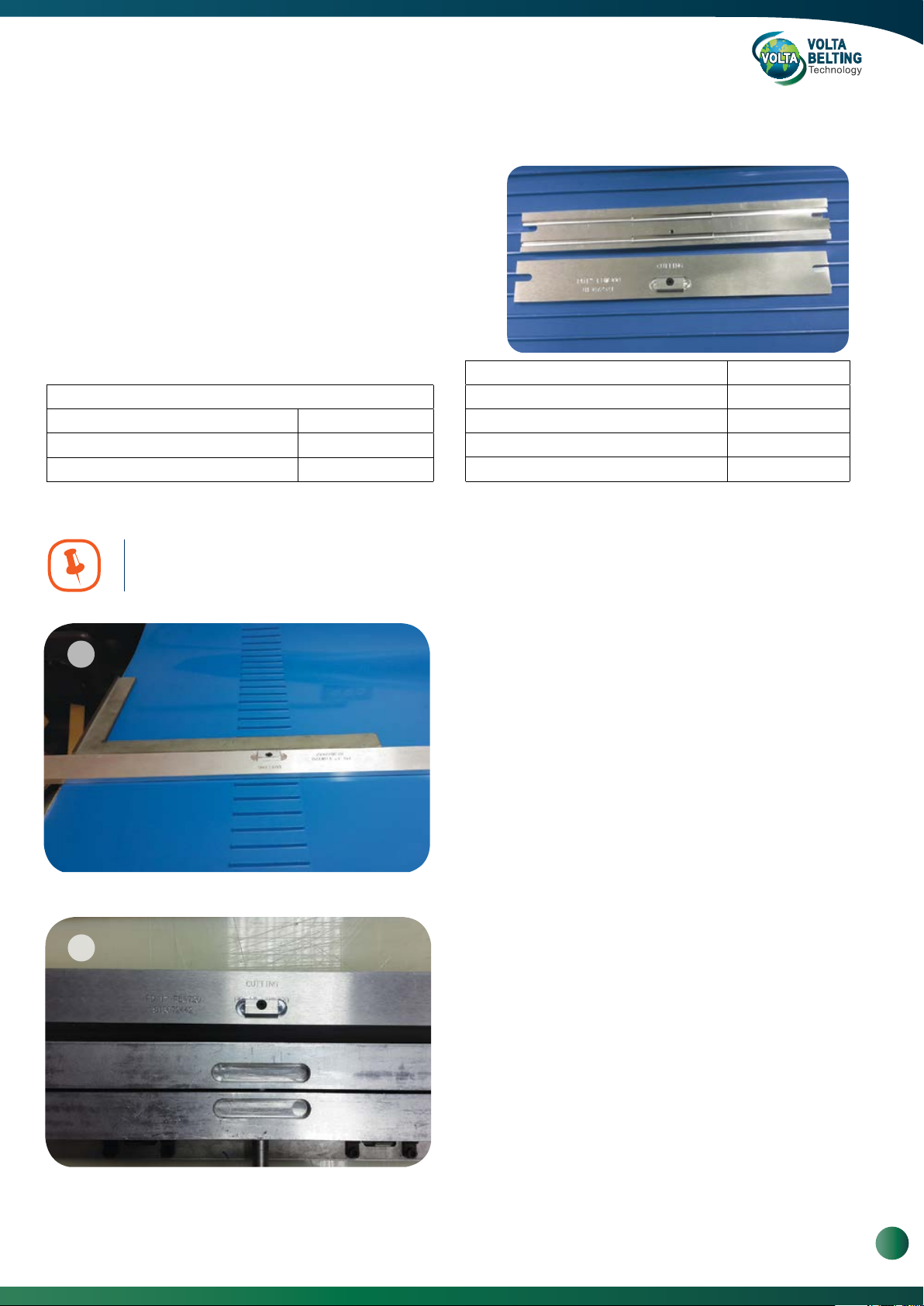
Insert the Cutting Bar at an angle between the Patterns
when the “Cutting” engraving (on the bar) and the belt
scrap is on the right-hand side. Push the cutting bar
toward the “Cutting” side and cut the first side with a
sharp knife. Measure the belt length and mark other end.
3
The weld is performed at an angle alongside the pattern.
There will be about 15 mm difference on the final length
of the belt according to the cutting line between the
patterns.
Rotate the cutting bar 180 degree, and insert the Cutting
Bar as close to the required size. Make sure that the
scrap and the “Cutting” engraving (on the bar) are on
your right-hand side. Add or deduct from the length of the
belt according to the position of the pattern.
4
Position the adapter on top of the belt with the «Welding»
side facing outward, position the belt and the adapter on
the FBW.
www.voltabelting.com
15

Welding & Fabrication Tools FBW-Flat Butt Welding System Model II
5
Insert the cross bar on the first side and repeat the same
stages on the other side. As the cut is in an angle, position
the belts ends according to reinforced belt joining
instructions (Page 13). Weld the belt according to the
instructions as described in the FBW Users Manual.
6
After the belt is cooled down, trim the weld with the ‘V’
shape knife. Use liquid soap to improve the cut if
required. Turn the belt and position it on top of the cutting
bar in a way that the spikes are inserted to the grooves,
this will allow you an easy trim of the underside. Check
the weld and perform “cosmetic” finish if necessary. A
good weld will be free of cracks and defects.
16
Volta Belting Technology Ltd.
4.4. Welding Cresent top (CT)
The weld is performed at an angle alongside the crescent pattern. There will be a 20 mm difference on the final length of
the belt according to the cutting line between the patterns.
Required Tools:
FBW Welding Kit
CT Cutting Bar for all FBW welding tool sizes Cat. # 81626365
Wood Chisel 6 mm (¼”)
You must be familiar with the instructions for welding with FBW before continuing
with this procedure.
1 2
Place the belt with the pattern facing to the left as shown
in the picture. Insert the Cutting Bar at an angle between
the patterns when the “Cutting” engraving (on the bar) and
the belt scrap is on the right-hand side. Cut the belt with a
sharp knife. If the belt is wider than the adapter, cut the
belt in two steps.
3
21
Weld the belt according to the instructions as described
in the FBW Intruction Manual (Page 13). When welding
belts made of L material, be careful and use less
pressure during the melting process and tightening after
melting.
Go to the other side of the belt and insert the Cutting Bar
as close to the required size. Make sure that the scrap and
the “Cutting” engraving (on the bar) are on your right-hand
side. To carry out this step, please stand on the opposite
side of the belt. Add or deduct from the length of the belt
according to the position of the pattern.
4
22
After cooling the belt, trim the weld with a wood chisel
when the flat side is facing the belt. Use liquid soap to
improve the cut if required. Turn the belt and trim the
bottom weld as usual. Check the weld and perform
“cosmetic” finish if necessary. A good weld will be free of
cracks and defects.
www.voltabelting.com
17
Welding & Fabrication Tools FBW-Flat Butt Welding System Model II
5. Instructions for Splicing Reinforced Flat Belts
Reinforced belts must be spliced in an angle (15° - 45°).
1 2
a. Prepare the Control Box and Pliers.
b. Cut both ends of the belt to the desired angle.
3
Position the second belt end on the opposite Pliers base.
c.
Ensure that there is an offset of 1 mm. This offset will
compensate for the material melted during welding and
ensure a smooth Straight edge.
Align the sharp upper edge of the belt with a reference
d.
mark on the Belt Locator Bar and press the belt onto the
doublesided tape.
Locator Bar
1 mm offset
4 5
f. Mount the Crossbars on the Pliers. Perfom weld as per
welding instructions.
18
Volta Belting Technology Ltd.
g. After trimming the weld, check that the belt edge is
aligned. A small disalignment may be trimmed.

6. Instructions for Welding Narrow Belts
The FBW models 301, 721 and 1061 can be used to weld narrow belts from 150 mm, by using double-sided tape
and without assembling the Crossbars. Observe the following rules:
a. Use good quality tape and make sure it is thoroughly adhered to the Pliers.
b. When welding reinforced belts, work upside down with the fabric facing upwards.
c. If the belt still moves while welding, raise the welding temperature by 15°C to 20°C to allow an easier melting of
the material and reduce the pressure required. When you finish, return the Temperature Controller to 220° C.
7. Instructions for Welding H Material Belts
The procedures for welding M and H family materials are basically the same. However when welding H family belts
it is necessary to be extra careful. The following are specific areas to watch out for:
a. When welding H material belts, and especially belts 4 mm thick or more, in ambient conditions of low
temperature and high humidity, it is necessary to warm the belt ends before welding.
b. With the belt ends secured in the Pliers, use a Leister Hot Air Gun to direct hot air over the belts’ ends for
approximately 2 minutes.
c. Without delay continue with the standard welding procedures described above.
d. If you do not have a Leister Hot Air Gun, you can place the Welder in the Pliers over the Pliers supports. Close
the Pliers without bringing the belt ends into contact with the Welder at least for a minute. The heat from the
Welder will warm the belt ends before you begin to weld.
e. When you bring the belt ends in contact with the Welder, press gently until the two ends have an even melt
along the entire length of both sides of the Welder. At this point stop pressing and maintain this position for
approximately 20 seconds. This allows the heat from the Welder to penetrate farther into the “H” material providing
a sufficiently large softened area to ensure a good weld. Open the Pliers quickly and with a “snap”, which will
prevent material from sticking to the Welder.
Release pressure, remove the Welder continue with the standard welding procedures described above.
f. Using the Operating Handle, quickly close the pliers, because the H material cools down quickly. When working
with H material belts, especially those that are 4 mm or thicker, apply extra pressure when closing the belt. This is
needed to force any air bubbles out of the joint. However, remember that applying too much pressure will reduce
the quality of the weld by forcing all of the melted material out of the area of the joint and leaving only cold
material.
g. The splice must be left to cool for at least 10 minutes after welding. Checking the splice by bending it too soon
will weaken or break the splice.
h. Because of the care needed to ensure a quality weld, it is important to perform several trial welds before
welding a belt. This will allow you to get the feel for the pressure required while welding and closing the Pliers after
welding. If you still have problems, please contact Volta for aditional technical advice.
www.voltabelting.com
19
Welding & Fabrication Tools FBW-Flat Butt Welding System Model II
8. Welding Positive Drive Belts
8.1. Instructions for Welding SuperDrive™ H/M Material Belts
Using FBW-301, FBW-721, FBW-1061 or FBW-1301.
21
It is Essential to carry out several welding trails to become familiar with welding the
Positive Drive conveyor belts.
22
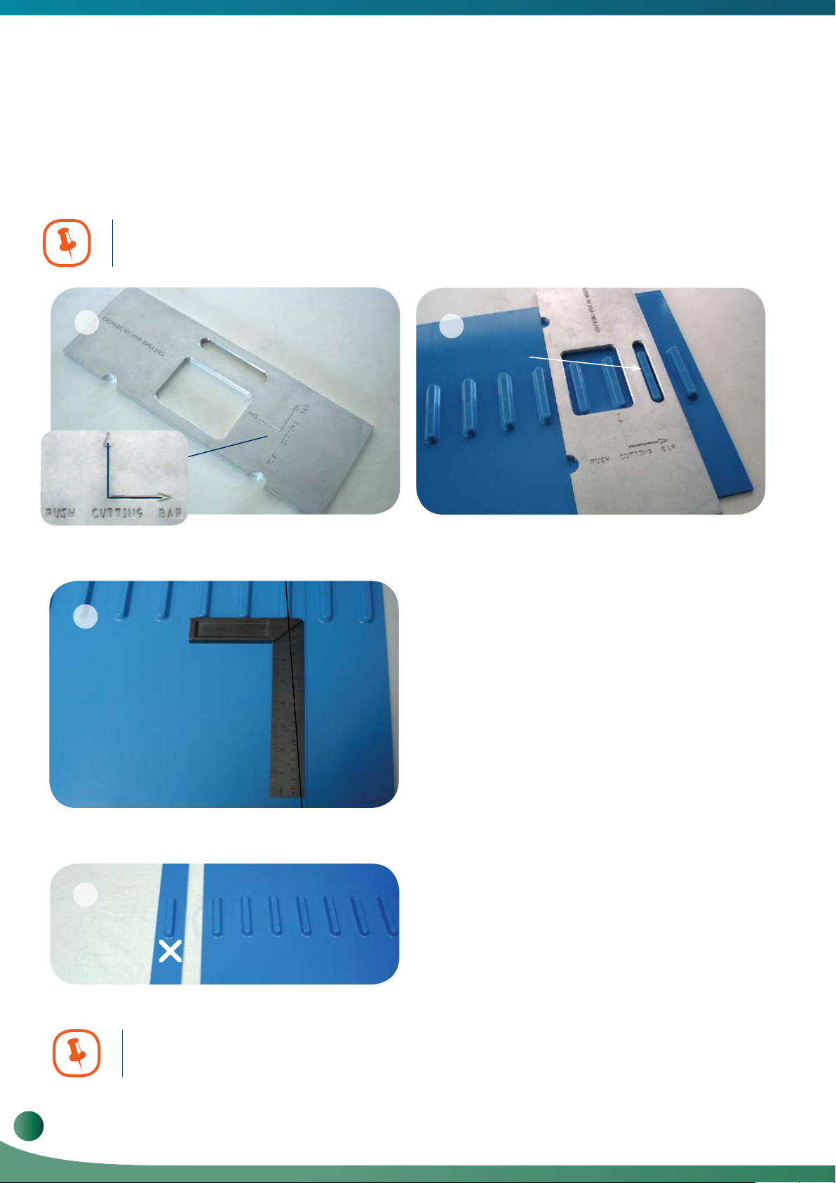
1
PUSH CUT TING BAR
The cutting bar is marked with positioning arrows as
1.
per photo 1.
3
2
No Gap
a.
Use the Cutting Bar to cut the belt between the teeth,
to ensure a 90º cut and the correct pitch. Push the
cutting bar away from you and then against the right
side until the single tooth stencil fits exactly in line with
the tooth, giving you a perfect 90º position for marking
your line.Draw a line and then check that the line is
parallel to the teeth. Photo’s 2 & 3. When cutting the
belt this line will help us to make sure that the cut is
square.
4
Tip. Use double sided tape on the bottom side of the cutting bar to prevent
slippage while cutting.
20
Volta Belting Technology Ltd.
Reposition the cutting bar make a clean cut using a
b.
sharp knife. When cutting the SD, we will have 2
ends one usable and one unusable (Photo 4, 5, 6)
this is due to the fact that we did not cut in the middle
of the pitch.
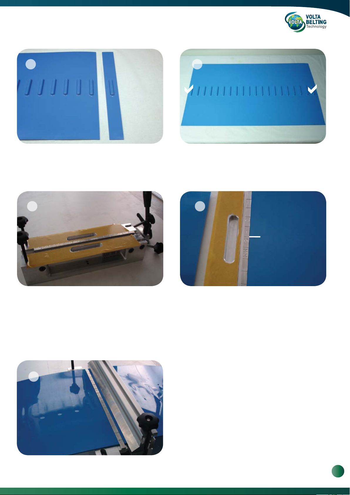
5 6
Now you must turn the cutting bar 180º and cut the
c.
second end of the belt so the scrap/unusable piece will
not be part of the belt. Both egdes of the belt must be
cut so that both the final ends are usable (1/2
pitch+2 to 3mm).
d.
7
Place double-sided tape on both sections of the Pliers.
2. 3.
Cut the tape away from the teeth grooves in the base.
The end result is that both ends of the belt will have a
combined pitch of SuperDrive™ tooth pitch + 3-4mm.
When welding the belt, those 3-4mm will melt and the
final pitch should be the exact pitch needed.
A pitch of - (Minus) 1 to 2mm is acceptable.
8
Position the locator bar as per normal operation of 3mm
-5mm belt, and then slide it until one of the positioning lines
is in the center of the groove. (Photo 8)
Remove the protective paper from the double-sided tape on one side and position the belt. The difference in working
4.
with the SuperDrive™ belt is that you must position the teeth over the groove before bringing the rest of the belt into
contact with the tape. To make this easier mark the center of the tooth on the top side of the belt and aline it against the
central positioning line.Press the belt against the locator bar and onto the tape to ensure a firm, consistant contact
(Photo 8).
Position the second belt end against the locator bar and fix
5.
the belt with the cross bar. (Photo 9)
9
Position the FBW Welder in place. Weld the belt
6.
according to the welding instructions in the FBW Manual.
Check the weld for any cracks or bubbles, if needed cut the
7.
belt and rejoin it (you will lose about 80mm from the belt length).
8.
Check the pitch; pitch larger than normal is not acceptable,
however welding results with pitch up to 2mm shorter is
acceptable.
www.voltabelting.com
21
Welding & Fabrication Tools FBW-Flat Butt Welding System Model II
8.2. Instructions for welding SuperDrive™ Belts Using FBW Adapter
For owners of the FBW-721 FBW-1061 and FBW-1301, Volta has prepared an Adapter kit for welding SuperDrive™
21
‘H’ and ‘M’ material belts.
For FBW-301
Cutting Bar, SuperDrive™ H/M (Fig. 1)
Adapter Bar, SuperDrive™ H/M (Fig. 2)
Locator Bar Spacer, SuperDrive™ H/M (Fig. 3)
Positioner for welder (Fig. 4)
Cutting Bar -
SuperDrive™ H/M
FBW Adapter Bar -
SuperDrive™ H/M
Cat. #8162567
Cat. #81307252
Cat. #81625902
Fig. 2Fig. 1
22
For FBW-721 For FBW-1061 FBW-1301
Cat. #8 1625901 Cat. # 81625907 Cat. #81626192
Cat. #81307242 Cat. # 81310602 Cat. #81313001
Cat. # 81625903 Cat. # 81625905 Cat. #81625906
Cat.#81626342
Fig. 3
Locator Bar Spacer
- SuperDrive™ H/M
Fig. 4
Positioner for
welder
Welding Instructions:
Apply double-sided tape to the exposed surface of the
a.
Use the Cutting Bar to cut the belt between the teeth.
To ensure a 90° cut, Repeat stages a-d on page 15-16.
Position the Locator Bar Spacer and the Adapters on
b.
the Pliers Base. Raise the two hinged Locking Screws
to a vertical position and close and lock the Pliers
(see figure below).
FBW with adapters and
Locator Bar Spacer
FBW Pliers with adapters and Locator Bar Spacer in place
Locking Screws
c.
Adapters and cut away the tape from the SuperDrive™
tooth grooves.
Remove the protective paper from the double-sided tape
d.
on one side and position the belt. The difference in working
with the SuperDrive™ belt is that you must position the tooth
over the groove before bringing the rest of the belt into contact
with the tape. Press the belt onto the tape to ensure a firm
and consistent contact.
Release the Pliers and adjust the Locator Bar so that the
e.
belt edge matches one of the scribe marks and re-lock
the Pliers.
f.
Position the other belt end using the scribe mark on the
Locator Bar Spacer to align the belt.
g.
Continue the welding process as for a standard flat belt.
8.3. Positioner for Welder
Is available in the kits FBW1301 and FBW1701 PD & Mini and is used for welding all the Volta belts where an adapter
is needed .
- Prior heating the wand connect both Positioners to both end of the wand. (Pic.1)
- The adaptors of the DD, DDSP, 1" pitch positive drive belts and impression top belts elevate the belt.
21
The Positioners keep the welder leveled with the top bars. (Pic.2)
22
Volta Belting Technology Ltd.

8.4. Welding DualDriveTM with FBW and Adapter
To ensure an accurate and efficient weld of DualDriveTM belts when splicing with the FBW Welder, choose the DD
Adapter suitable to your FBW Tool from the table below. If you haven’t welded this product before, weld a section
of a trial belt before welding your Volta conveyor belt.
Required Tools:
FBW Welding Kit
DD Adapter Set for FBW - 301 Cat. #813072530
DD Adapter Set for FBW - 721 Cat. #81307245
DD Adapter Set for FBW - 1061 Cat. #81310605
You must be familiar with the instructions for welding with FBW before continuing
with this procedure.
1 2
DD Adapter Set for FBW - 1301* Cat. #81313005
DD Adapter Set for FBW - 1701*
V Trim Knife Cat. #8153105
Stoppers (2 units) Cat. #81626340
Positioner for welder**
* Non-standard
** Positioner for welder FBW - 1301 and FBW - 1701 only.
Instructions on Page 22.
Cat. #813013019
Cat. #81626342
To keep the correct pitch, place the stopper on the welder.
Loosen the screws of the Stoppers and place them in the
groove on the end sides of the Welder.
Tightly secure the screws.
Do not assemble/disassemble stoppers when welder is hot.
3
Place the adapter on the belt and push the cutting bar
against the tooth towards the cutting side. Cut the first end
of the belt along the “Cutting” side. Turn the cutting bar
180º and cut the second end of the belt.
4
For the FBW-721 and FBW-1061 apply about 10cm of
double sided tape on the center plier base, this will hold the
adaptors in place.
www.voltabelting.com
23

Welding & Fabrication Tools FBW-Flat Butt Welding System Model II
21
5
Position the Adapters onto the Pliers with the “Cutting”
sides facing outwards. Position both sides of the belt on
the Pliers. The belts’ teeth should face down and
interlock with the grooves of the adapters.
7
22
6
Position the crossbar without tightening the knobs. Close
the plier and push the two ends together, this will align the
two ends of the belt with the adaptors. Now tighten the
FBW Crossbars.
8
Position the FBW Welder in place. Apply consistent and
gentle pressure until the Stoppers do not allow you to
continue. Immediately open the Pliers. Weld the belt
according to the welding instructions in the FBW Manual.
24
Volta Belting Technology Ltd.
Trim and check the weld. A good weld will be free of
cracks and defect. Pitch tolerance should be +0 mm,
-1mm.
8.5. Welding Mini SuperDrive™ and Mini DualDrive™
To ensure an accurate and efficient weld of Mini SuperDriveTM
and Mini DualDriveTM belts when splicing with the FBW Kit,
choose the MSD/MDD Adapter suitable to your FBW Tool from
the table below.
If you haven’t welded this product before, weld a section of a trial
belt before welding your Volta conveyor belt.
Required Tools:
FBW Welding Kit
PD 1” Adapter Set for FBW - 301 Cat. #813072541
PD 1” Adapter Set for FBW - 721 Cat. #813072442
PD 1” Adapter Set for FBW - 1061 Cat. #813106042
An operator must be made familiar with the standard practice for welding with an
FBW prior to continuing with this procedure.
1
PD 1” Adapter Set for FBW - 1301* Cat. #81313017
PD 1” Adapter Set for FBW - 1701* Cat. #81313024
Positioner for welder** Cat.#81626342
V Trim Knife Narrow Cat. #8153108
Utility Knife
* Non-standard
** Positioner for welder FBW - 1301 and FBW - 1701 only.
Instructions on Page 22.
Select the PD 1” Adapter suited to your existing tool.
Place the adapter on the belt and cut each end of the belt
in turn using the adapter edge marked “Cutting”. This
ensures the correct tooth pitch. Take great care to ensure
that the cut is accurate and straight.
Position both Adapters onto the FBW belt clamp so that
2
the location lugs fit into the existing SuperDriveTM slots.
Ensure that the Adapters are aligned with each other.
Small sections of double-sided tape are essential to fix
the adapters onto the clamp bed.
www.voltabelting.com
25

Welding & Fabrication Tools FBW-Flat Butt Welding System Model II
3
Double-sided adhesive tape should be applied to the top
of the adaptors as indicated in the photo.
It is important that the whole belt width will be taped
using the double sided adhesive tape. The tape should
be trimmed to fit the pattern of the grooves.
4
Position both sides of the belt so that the teeth face down
and mesh with the adapter grooves.
5 6
Position and tighten the FBW Crossbars over both belt
edges. Weld the belt according to the FBW User Manual
Instructions.
Trim and check the weld. A good weld will be free of cracks
and defect. Pitch tolerance should be +0 mm, -1.0 mm.
26
Volta Belting Technology Ltd.
8.6. Welding Mini SuperDrive™ MiniCleat
To ensure an accurate and efficient weld of Mini SuperDrive™-MiniCleat belts when splicing with the FBW Kit, choose the
Adapter suitable to your FBW Tool from the table below. If you haven’t welded this product before, weld a section of a trial
belt before welding your Volta conveyor belt.
Required Tools:
FBW Welding kit (one of the following, according to your tool)
PD 1” Adapter Set for FBW 300/301 Cat. #813072538
PD 1” Adapter Set for FBW 720/721 Cat. #813072440
PD 1” Adapter Set for FBW 1060/1061 Cat. #813106040
You must be familiar with the instructions for welding with FBW
before continuing with this procedure.
1 2
PD 1” Adapter Set for FBW 1300/1301* Cat. #81313017
PD 1” Adapter Set for FBW 1700/1701* Cat. #81313020
MSD-MC Accessories Set Cat. #8153107MSDMC
* Non-standard
Choose the PD 1” Adapter that fits your pliers. Place the
adapter on the MSD side of the belt and cut the two ends
of the belt along the “Cutting” side. You must use this side
for cutting the belt to ensure correct pitch of the teeth.
Make sure that the cut is accurate and straight.
3 4
Place double sided tape on the top surface of the
adapters and carefully trim the tape along the MSD
grooves in the adapters with a utility knife. The double
sided tape will help achieve a better, bubble free, weld.
Position the Adapters onto the Pliers so the location block
is inserted into the SuperDrive slots on the pliers. Make
sure the Mini SuperDrive grooves in both adapters are
aligned. It is recommended to use small strips of double
sided tape to secure the adapters onto the Pliers.
Position both sides of the belt on the Pliers. The belt’s
MSD teeth should face down and interlock with the
grooves of the adapters.
www.voltabelting.com
27

Welding & Fabrication Tools FBW-Flat Butt Welding System Model II
5 6
>4mm
If the position of the MiniCleat is less than 4mm to the belt
edge, it is recommended to remove the MiniCleat from
the belt edge using the straight trim knife.
7 8
FBW inner side
Place a MDD belt (see figure 12) over the MSD-MC,
make sure the MDD tooth is close to the edge of the
FBW's inner side but does not exceed the edge. The
purpose of the MDD teeth is to apply pressure near the
welded edge to the belt to prevent the belt from moving
during the welding.
MDD "press pad" to be used as adapter
9 10
Rub a small amount of soap on the MiniCleat and on the
blade of the straight trim knife (see figure 11). Close the
FBW sides to use the second adaptor as an anvil while
carefully cutting the MiniCleat away from the belt.
4mm support strips
An alternative to using MDD as "press pad", a strip
(see figure 7) is to use a plain 4mm thik belt strip
Position and tighten the FBW Crossbars. Weld the belt
according to the FBW User Manual Instructions.
11 12
The Straight trim knife is used for cutting a Mini Cleat
away from the belt. Cat. #8153107
28
Volta Belting Technology Ltd.
Trim and check the weld. A good weld will be free of
cracks and defect. Pitch tolerance should be +0 mm,
-1.0 mm.
In order to maintain the pressure applied by means of the
FBW crossbars on the belt, we recommend using
sections of MDD belt as "press pads" with a width of
exactly 3 teeth pitch as shown in figure.

8.7.
Welding DualDrive™ SP (DDSP) Belts and DDSP Lace
To ensure an accurate and efficient weld of DualDrive
product before, weld a section of a trial belt before welding your Volta conveyor belt.
* For welding DD SP Lace follow the same instructions as seen on pages 24-25.
TM
SP belts, use FBW DualDriveTM SP Adapter Kit. If you haven’t welded this
Required Tools:
FBW Welding Kit
DDSP Adapter Set for FBW - 301 Cat. #81626317
DDSP Adapter Set for FBW - 721 Cat. #81626327
DDSP Adapter Set for FBW - 1061 Cat. #81626332
You must be familiar with the instructions for welding with FBW before
continuing with this procedure.
1
DDSP Adapter Set for FBW - 1301* Cat. #81626337
Stoppers (2 units) Cat. #81626340
Positioner for welder** Cat. #81626342
V Trim Knife Narrow Cat. #8153108
Utility Knife
* Non-standard
** Positioner for welder FBW - 1301 and FBW - 1701 only.
Instructions on Page 22.
2
To keep the correct pitch, place the stopper on the
welder. Loosen the screws of the Stoppers and place
them in the groove on the end sides of the Welder. Tightly
secure the screws.
Do not assemble/disassemble stoppers when welder is hot.
3
Heat up the Welder. Choose the DualDriveTM SP Adapter
that fits to the Pliers (see Required Tools above). Cut the
two ends of the belt along the side marked Cutting.
Ensure that the cut is accurate and straight.
4
narrow side
Apply strips of good quality Double-Sided Tape on the
Adapters on the grooved surfaces from the narrow side
inwards. Trim the unnecessary tape from the grooves.
www.voltabelting.com
29

Welding & Fabrication Tools FBW-Flat Butt Welding System Model II
5
22
Position the Adapters onto the Pliers with the narrow sides
facing inwards. Position both sides of the belt on the Pliers.
The belts’ teeth should face down and interlock with the
grooves of the adaptors, tighten the FBW Crossbars.
7
6
Position the FBW Welder in place. Apply consistent and gentle
pressure until the Stoppers do not allow you to continue.
Immediately open the Pliers. Weld the belt according to the
welding instructions in the FBW Manual.
8
Trim the excess from both sides of the belt. Apply soapy
water for easier trimming.
30
Volta Belting Technology Ltd.
Trim and check the weld. A good weld will be free of cracks
and defects. Pitch tolerance should be +0.8 mm, -0.8 mm.

8.8. Welding Volta Hinge Lace with FBW
There are occasions when it may be necessary to splice the flat belt using Volta Hinge Lace. This hinge lace is suitable for
belt thicknesses of 2.5 to 4 mm. When working with lace, it is important that you work according to the following instructions.
If you haven’t welded this product before, weld a section of a trial belt before welding your Volta conveyor belt.
You must be familiar with the welding instruction in the FBW Manual before
continuing with this procedure.
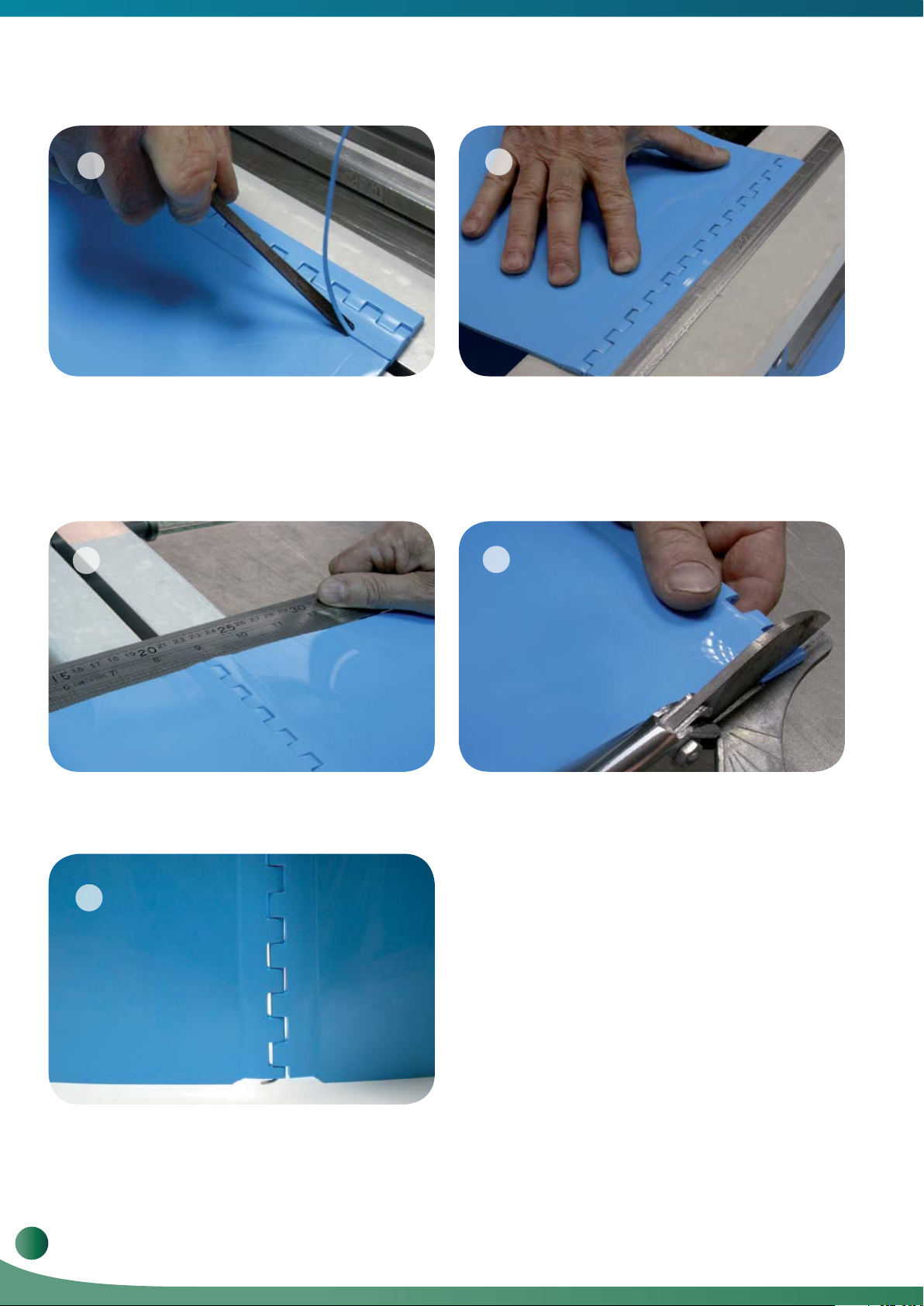
1 2
Cut the belt to the required length taking into consideration
the lace. Join the lace and cut to the belt’s width.
3
Position the lace as you did the belt. Make sure the lace
sides interlock and the flat side faces down. The lace
should be symmetrically aligned to the belt.
Position one side of the belt on the Pliers according to
the welding instructions in the FBW Manual. Remember
to use double-sided tape for this task.
4
Weld the belt to the lace according to the welding
instructions for FBW. The thicker the belt, the longer the
melt should be to match the thickness of your belt.
www.voltabelting.com
31
Welding & Fabrication Tools FBW-Flat Butt Welding System Model II
21
5
Heat a Round Chisel with the Leister Hot Air Gun and trim
the excess from the top of the belt, or apply some soapy
water for easier trimming. You may use a V-Knife or a
Lesiter Knife to trim the excess from the bottom of the belt.
7
22
6
Repeat from Step 3 to weld the other end of the belt.
8
Make sure the lace and the belt are symmetrically aligned.
9
Belt with Volta Hinge Lace.
32
Volta Belting Technology Ltd.
Trim the lace approximately 5 mm from each side. Insert
a hinge pin into the slit and check its symmetry and
adequacy.

9. General Tips
Before splicing “H” family belts, FELW 1.6, FELW-2, FRL 2 or belts with special adapters, it is strongly recommended that you
spend a few minutes practicing before welding the actual belt.
10. Troubleshooting Guide
Symptom Possible cause Suggested solution
Unstable temperature
reading
Welder overheating Thermocouple Contact a qualified technician.
Irregularity in the excess Belt not cut properly. Re-cut and re-weld.
Belt moves during
welding
Bubbles in the joint Welder Temperature is too high.
Bad or inadequate joint
on “H” material belts
Thermocouple Contact a qualified technician.
Low quality double-sided tape. Use a high-quality double-sided tape.
Inadequate or uneven pressure on the
Crossbars.
Insufficient pressure when closing the Pliers
after removing the Welder, or too slow an
action.
Pressing too hard when closing the Pliers
after welding.
Too slow an operation when closing the
Pliers after welding.
Make sure the Crossbars have been properly tightened.
Refer to Welding Instructions.
Ensure that the Temperature Controller has been
properly setup.
Perform a number of trial welds to improve closing
pressure and/ or speed.
Reduce pressure when closing the Pliers. Refer to
Page 14, Instructions for Welding “H” Material.
Repeat the procedure to increase speed Refer to
Page 14, Instructions for Welding “H” Material.
www.voltabelting.com
33
Welding & Fabrication Tools FBW-Flat Butt Welding System Model II
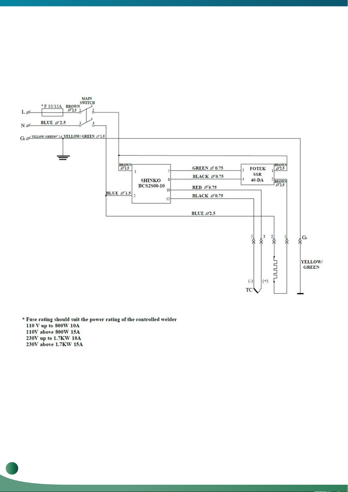
11. FBW Controller and Welder Electrical Diagram
Model SHINKO-BCS2S00-10
34
Volta Belting Technology Ltd.
FBW Welder and Temperature Controller Electrical Schematic
12. Calibrating the FBW/PDW Welder Control box & Welder Bar
These instructions apply to Temperature Controller Model
SHINKO-BCS2S00-10
Before calibrating the welder, make sure it is not plugged to a power source and that the
Welder Bar is at room temperature.
Connect the Welder-Bar to the controller and secure the latch on the connector.
Place the Welder Bar up-right on an even surface where it is safe for it to heat up.
DO NOT Touch the Welder Bar as it heats up. Use protective gloves and use the bar
handle to hold the Welder Bar.
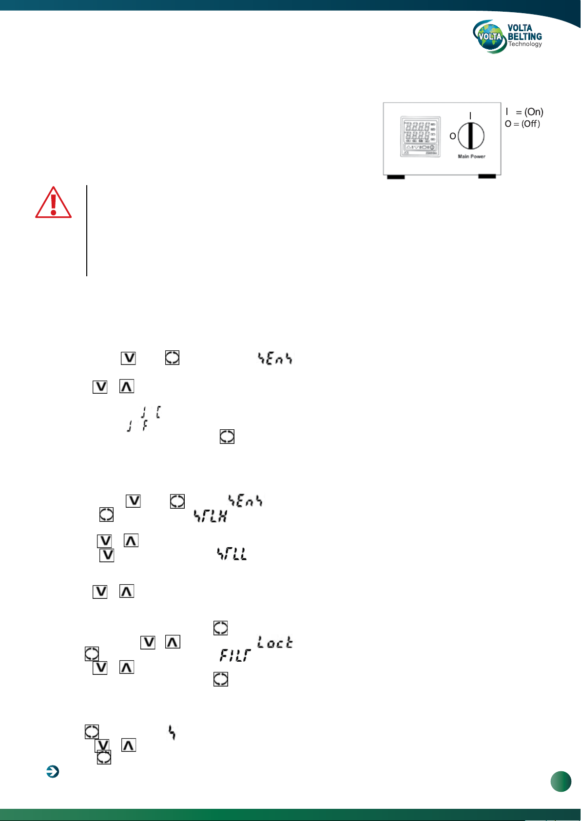
1. Temperature Scale Selection
Select Fahrenheit or Celsius temperature scales.
a. Plug the control box to an appropriate outlet and Turn the Main Power switch on to ‘I’ and wait until the measured
temperature is displayed on the PV line & the SV line displays the temperature set value. This state is referred to from here
on as the "Normal Display".
b. Press and hold & then for 3 seconds until appears in the PV line.
On the SV line the selected Thermocouple Type and temperature scale are shown.
c. Use the or to scroll through the thermocouple & scale options. There are about 20 options to scroll through.
CHOOSE:
either thermocouple
or thermocouple
d. To save your selection long press on the key until the display returns to Normal display.
= Centigrade (°C) scale.
= Fahrenheit (°F) scale.
2. Temperature Limit Setting
Sets the Welder’s maximum allowable temperature.
Select the Welder limits temperature.
a. Press and holdd & then keys until appears in the PV line.
b. Press the button. The symbol will appear in the PV line.
The value on the SV line is the maximal allowable set temperature value.
c. Press on or to set the maximum allowable temperature (250°C / 482°F).
d. Press the button once. The symbol will appear in the PV line.
The value on the SV line is the minimal allowable set temperature value.
NOTE: There could be a minus (-) sign to the left of the value.
e. Use the or keys to set the minimum allowable temperatures are between
0°C / 0°F – (factory settings) to 200°C / 390°F.
Setting higher minimum may prevent error in setting the desired working temperature.
f. To save your selection press & hold on until the display changes back to Normal display.
g. Press and hold both & for 3 seconds until appears in PV line.
h. Press several times until the symbol appears in the PV line.
i. Use the or keys to set the value to (1.0).
j. To save your selection press & hold on until the display changes back to Normal display.
3. Welder Working Temperature
Set the Welder operating temperature.
a. Press until the symbol appears on the PV line.
b. Press on or to set the desired temperature (220°C / 428°F).
c. Press on key once to save and return to the Normal display.
Turn the Main Power switch off to “O”.
www.voltabelting.com
35

Welding & Fabrication Tools FBW-Flat Butt Welding System Model II
4. Temperature Correction (Off-Set)
This step provides compensation the difference between the actual temperature on Welder Bar and that measured by
the controller.
This procedure should be performed if:
• A major system component was replaced i.e. control box/controller Welder Bar/heating element.
• Change of temperature scale from °C to °F or wise-versa.
Calibrated industrial face thermometer capable of measuring temperatures in the range 150°C / 300°F to 300°C / 570°F, is
required for this step.
a. Turn the main switch on the control box on "I" and wait until the display turns to Normal.
b. Press and hold both & keys for 3 seconds until appears in the PV line and 4 non-blinking dots on the SV
line.
c. Press several times until the symbol appears on the PV line.
d. Using the or keys, set the value on SV line to 50. Make sure it is not (-50).
e. To save your selection press & hold on until the display changes back to Normal display.
f. Wait for the PV line to stabilized (even if it's not equal to the SV Line).
g. Use the thermometer and measure the temperature on the surface of the Welder Bar at a point between 200 to 250mm (8" to
10") from the cable entry side.
A large difference can be expected between this measure and the value displayed on the PV line.
Make sure you measure the temperature at about the same point every time.
h. Subtract the thermometer temp from the temperature displayed on the PV line.
Record this value (it may be negative).
If this value is less than 5°C / 9°F offset calibration is completed.
i. Press and hold both & keys for 3 seconds until appears in the PV line and 4 non-blinking dots on the SV
line and then Press
several times until the symbol appears on the PV line.
j. If this is the first iteration the value 50 appears on the SV line (as set in step c. above).
k. Subtract the recorded value from the SV value (negative values are possible).
l. Using or to change the SV value to the value you calculated in (j.) above.
m. To save your selection press & hold on until the display changes back to Normal display.
n. Allow about 10 minutes for the welder temperature to stabilize.
o. Repeat the procedure form step (g.) above.
Example:
Temperature Controller PV display shows a temperature of 428°F.
Welder temperature is measured as being 394°F.
On our first iteration the difference is 428-394 = 34.
Performing step (h.) we get the value 50.
50-34 = 16 we decrease the SV Value to 16.
And press & hold
Waiting for the temperature to stabilize it again shows 428 on the PV line.
We now measure a temperature of 408°F i.e. the difference is 20.
At Step (h.) the SV value is 16 (16-20) = -4. We decrease the SV value to (-4).
to return to normal display.
5. Auto Tuning
This step calibrates the Temperature Controller to a new Welder.
Perform the Auto-tune procedure in the following cases:
• You performed Temperature Correction (Off-Set) (section 4 above).
• The controller or the Welder Bar/heating element are replaced.
• There's a significant difference of the environment (indoor vs outdoor etc.).
a. Make sure the Welder Bar is properly connected and the latch connector is secured.
b. Make sure it is safe to let the Welder Bar to heat up.
c. Make sure the Welder Bar temperature is below 150°C / 300°F.
d. Turn the Main Power switch on “I”.
e. Press and hold & then for 3 seconds until (red) appears in the PV line and Four (4) non-blinking lights appears
on the SV line.
f. Press until the (green) appears on the SV Line.
g. Press to start the Auto Tuning cycle.
h. The display changes to Normal Display.
i. An orange "AT" is blinking on the Left side of the display.
j. Wait until the "AT" stops blinking (this process may take about 30 min.)
• Should an "Err" message appear on the display (sometimes with a code):
Turn the Power switch off "O" wait for the bar to cool and repeat from step (d.) above.
36
k. When the "AT" indication extinguishes the Welder Bar is ready for work.

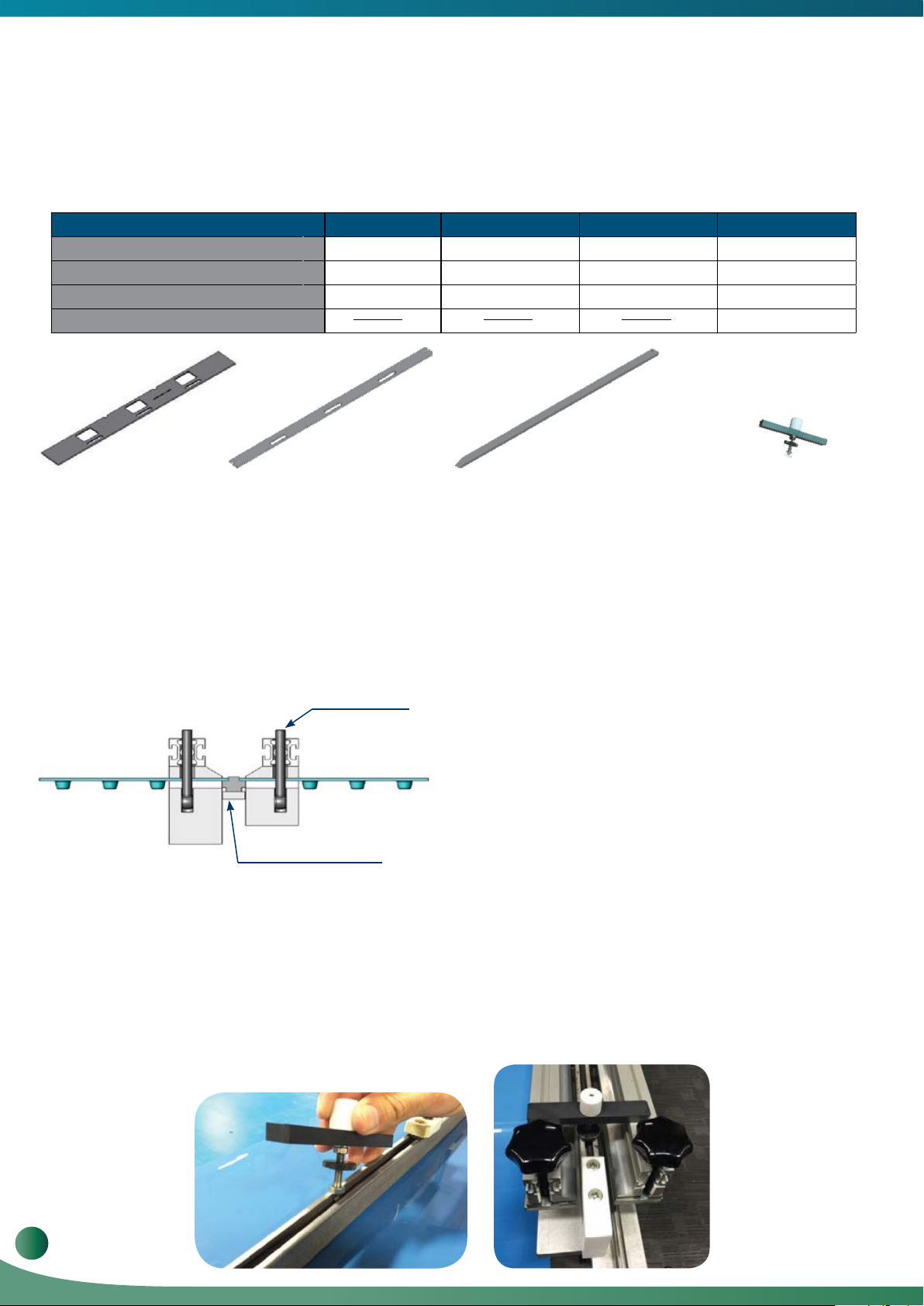
13. Pitch Gauge Measuring Tool for Volta Positive Drive Belts
UPPER
LOWER
1
2
3A
WELD
PITCH IS TOO BIG
3B
WELD
PITCH IS TOO SMALL
3C
WELD
PITCH IS OK
Volta Positive drive belts need to be welded endlessly while maintaining a correct pitch tolerance between the teeth
closest to the weld. A small tool has been developed to ensure this.
The Pitch Gauge Measuring Tool is not included in the FBW Welding kit.
This tool can be purchased as a separate unit - Cat.No. - 81307570.
22
Positive Drive Pitch Gauge Tool Instructions
Replacing the belt type gauge
blocks:
Remove the four bolts using the
supplied 3mm Allen key and
reconnect upper and lower to the
desired belt type gauge block.
Calibrating the gauge:
1. Unfasten the knob and place
the gauge blocks on two adjacent
belt teeth. (Not the teeth adjacent
to the weld).
2. Push the gauge base to the
position so it sits firmly to the
outer side of the gage block. (The
gauge blocks should sit firmly on
both teeth). Tighten the knob to
lock the gauge in place.
3. Checking the weld:
Place the gauge on the two closest teeth on both sides of the weld.
The gauge should sit firmly on both teeth. If there is a small gap as seen in picture 3a the pitch is within the allowed
tolerance. In case the gauge doesn’t sits firmly on the teeth refer to pictures 3b and 3c.
www.voltabelting.com
37

With Volta Tools You Can Never Go Wrong!
•
Fast and simple belt installation.
• Unique and versatile design - compact, rugged and easy-to-use.
• Designed for both shop and field use.
• Light-weight construction.
• Usually does not require cooling water or air pressure.
• Convenient design and method of storing and carrying your tools.
• Welds and fabrications are strong, reliable and will last as long as your belt life.
Corporate Headquarters
Sales and Manufacturing
sales@voltabelting.com
Volta Belting makes no warranty with respect to any of its products for a particular purpose.
See Volta General Terms and Conditions.
USA
Tel: +1 973 276 7905
Fax: +1 973 276 7908
Toll Free: 1-877-VOLTAUS
EUROPE
Tel: +31-546-580166
Fax: +31-546-579508S
www.volta-belting.com
Copyright© Volta Belting Technology Ltd.
CAT612EN00 - Ver.A.June 2019
 Loading...