

Page 1

LOW-VOLTAGE TRANSFORMER
INST
ALLATION GUIDE
Models:
VTR-100SL-SS
ATTENTION:
Please read this installation guide carefully to
ensure safe and efcient operation of this Power
Supply
Page 2
SAFETY GUIDELINES
Low voltage installation and maintenance is safe and presents
no risk for electric shock injury. However, there are regulations
that may apply and that should be followed by installers. The
following safety points may or may not be included in these
regulations - the installer is responsible for ensuring a compliant
installation.
◗ WARNING- RISK OF SHOCK. Install power unit at least 5 feet
(1.5m) from pool or spa and at least 10 feet (3.05m) from a
fountain.
◗ WARNING- install power unit in or on non-combustible materials
only.
◗ Power supply must be connected (using supplied power cord) to
GFCI-protected receptacle with an In-use cover.
◗ All VOLT
®
power supplies are indoor and outdoor rated, but we
recommend that the transformer be mounted outdoors. If mount-
ing indoors, check for local electrical codes that may apply.
◗ Power supply must be mounted in a vertical orientation with the
bottom plate at least 1 foot above the ground.
◗ In hot climates, avoid mounting in direct sunlight. Power unit will
get hot regardless of climate. This is normal for operation.
www.voltlighting.com
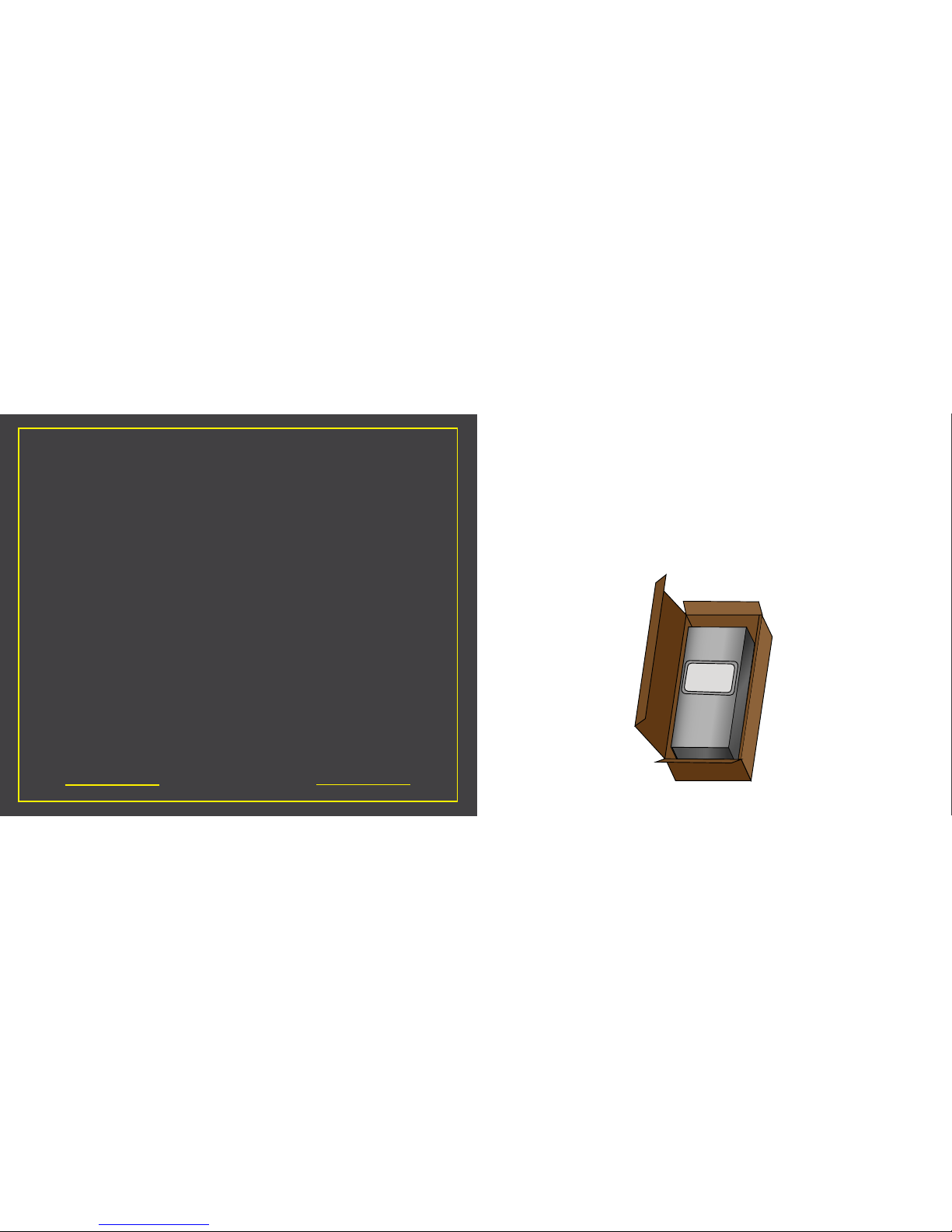
Open the shipping carton and carefully remove the
transformer, accessories, and hardware. Note that
transformer mounting hardware is not included. Inspect
contents for any damage that may have occured during
shipping.
Mounting Hardware
not included
Page 3

Your general capacity should have been determined prior to
purchasing your transformer. Circuit loads should not exceed 80%
of capacity. As a general rule, total light xture wattage should
not exceed 80% of transformer capacity. To determine your
total wattage, simply add up the wattage of all xture lamps.
This number should be 20% less than the transformer’s wattage
capacity. If you need help with this, give customer service a call
at 813-978-3700. If you are over capacity, your installation may
require a secondary or larger transformer.
DETERMINE THE LOAD
www.voltlighting.com
Notes:
_______________________________________________________
_______________________________________________________
_______________________________________________________
_______________________________________________________
_______________________________________________________
_______________________________________________________
_______________________________________________________
_______________________________________________________
_______________________________________________________
_______________________________________________________
_______________________________________________________
_______________________________________________________
_______________________________________________________
_______________________________________________________
_______________________________________________________
_______________________________________________________
_______________________________________________________
Page 4
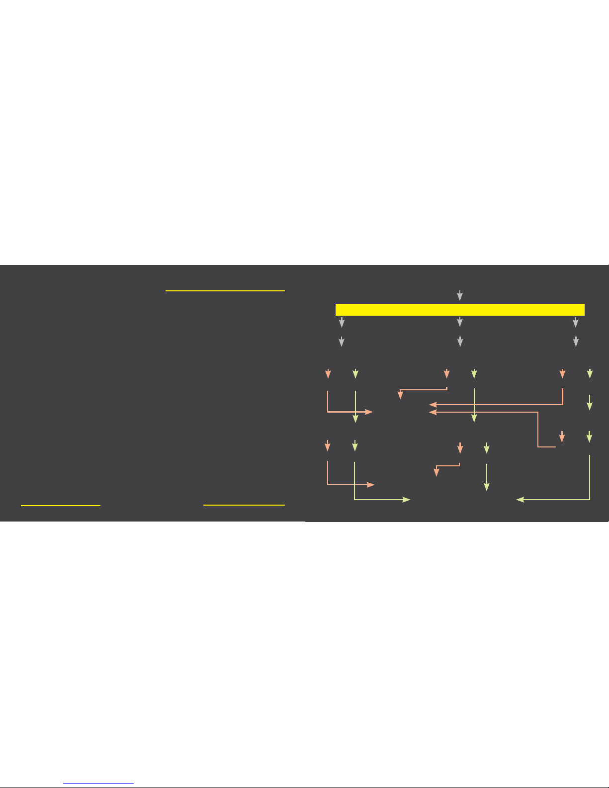
Will you be using Halogen or LED xtures?
What gauge cable do I need in order to run my Landscape Lighting System?
HALOGEN
Is the length of your
farthest run more than
100 feet?
Is the length of your
farthest run more than
100 feet?
Is the length of your
farthest run more than
100 feet?
12/2 Gauge cable
should be sucient for
your needs
10/2 Gauge cable should be
sucient for your needs
8/2 Gauge cable should be sucient for
your needs
Is the length of your
farthest run more than
200 feet?
Is the length of your
farthest run more than
200 feet?
Is the length of your
farthest run more than
200 feet?
BOTH LED
NO
NO
NO
NO
NO
NO
YES
YES
YES
YES
YES
YES
On the right, there is a diagram to help you determine what size
cable is needed for your lighting job. If you have questions or
concerns regarding this, you can give customer service a call at
(813)-978-3700 to speak with a live representative.
DETERMINE WIRE GAUGE
www.voltlighting.com
IMPORTANT! Please note that we do not
recommend any runs longer than 300 ft.
for low voltage lighting.
Page 5
Ready to Install?
If you have already designed your system, and mounted
your transformer, use the Quick Start Guide Steps
starting on the next page.
START HERE
www.voltlighting.com
Quick Start Guide Steps
1. Read the safety instructions and unpack your transformer.
2. Mount your transformer.
3. Run wires from transformer location to xtures or hubs.
4. Attach all wires to transformer terminals. For each paired wire, attach one
side to a common terminal and the other side to the voltage terminal.
5. Check that all of your connections are secure.
6. Plug in your transformer.
7. Flip the ON/OFF breaker switch upward to power on your transformer.
8. Check that your transformer pilot light and timer pilot light are both on.
9. Turn your timer clockwise to manual “On” mode.
10. Check that all of your xtures are on and functioning properly.
11. Measure the voltage at xtures or hubs.
12. If needed, use another voltage terminal (some transformers only have
one).
13. Set your timer to the desired function.
14. Close the transformer door using the locking mehanism to seal the unit
from weather and debris.
15. At Dusk, make any last minute adjustments to your xtures. Bury the
wire only after you have made these adjustments.
Page 6
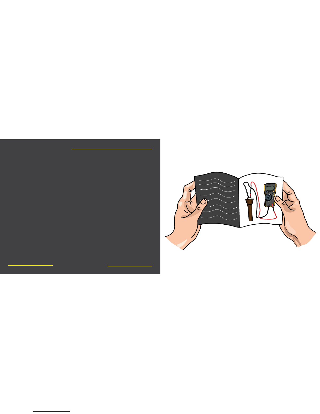
Read and understand the safety guidelines printed on back
of the front cover of this guide. If you have questions or
need help please call our help hotline at 813-978-3700 or
consult a licensed electrician in your area for any issues
requiring work on line voltage applications.
Quick Start Step 1
www.voltlighting.com
HOLD
MIN MAX
RANGE
AUTO-V
LoZ
OFF
V
Hz
V
mV
A
COM
+
V
AC
12.00
Page 7
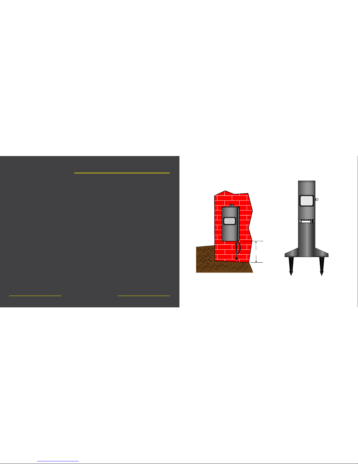
The transformer can be mounted directly to the wall or on the
optional pedestal. If mounting directly to the wall, be sure
to use wall anchors to insure your transformer is secure. With
either method, be sure that you are within 5 feet of a GCFI
protected outlet with an In-Use cover.
Quick Start Step 2
www.voltlighting.com
1’ Min.
Mounting Method 1:
Wall Mount
Mounting Method 2:
Pedestal Mount
4
H
r
s
6
H
r
s
8
H
r
s
1
0
H
r
s
O
F
F
O
N
D
a
w
n
D
u
s
k
-
2
H
r
s
Page 8
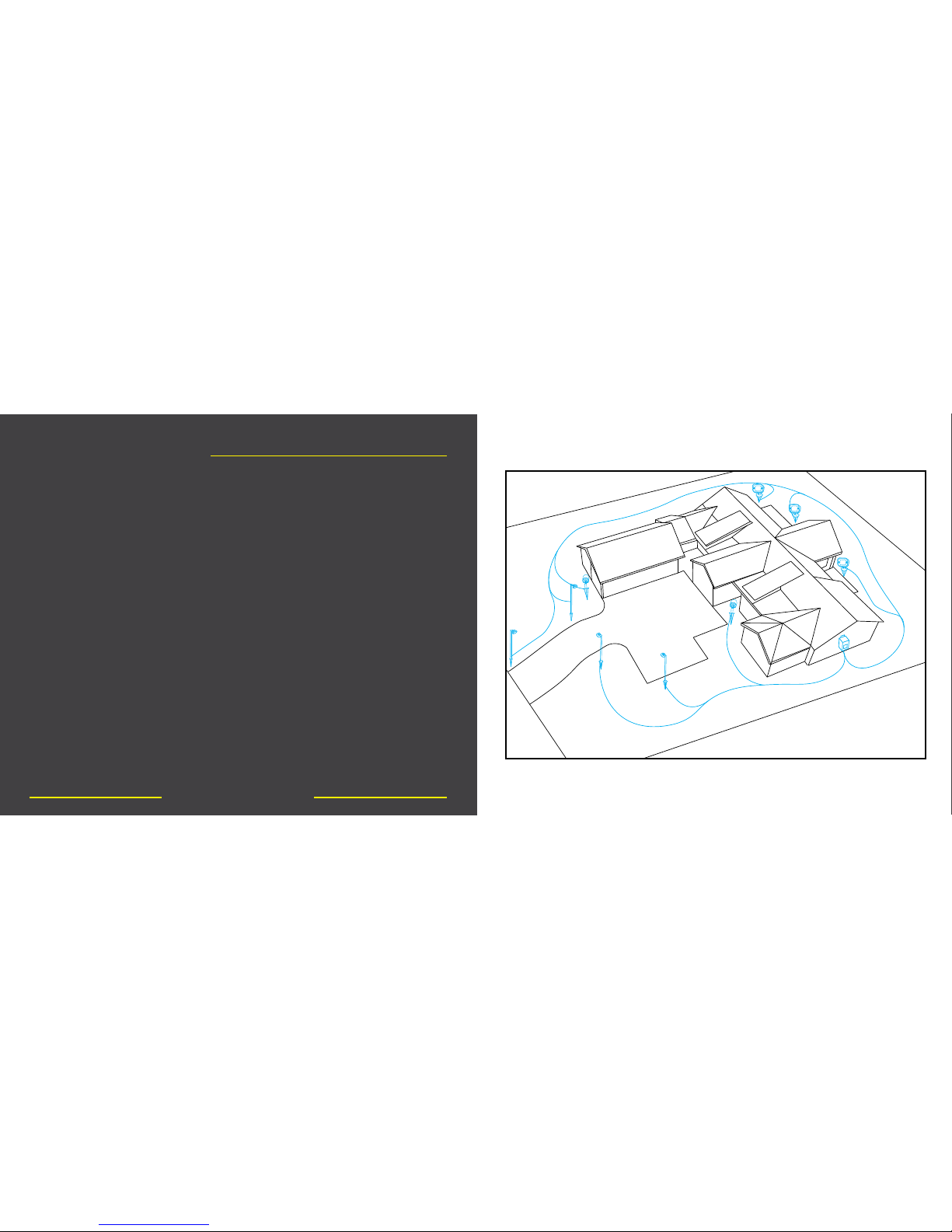
With your plans or layout in hand, run your wires from your
transformer to your hub and/or xture locations. Leave
extra slack as you may want to adjust xtures at night to
achieve your desired effect.
Quick Start Step 3
www.voltlighting.com
Page 9
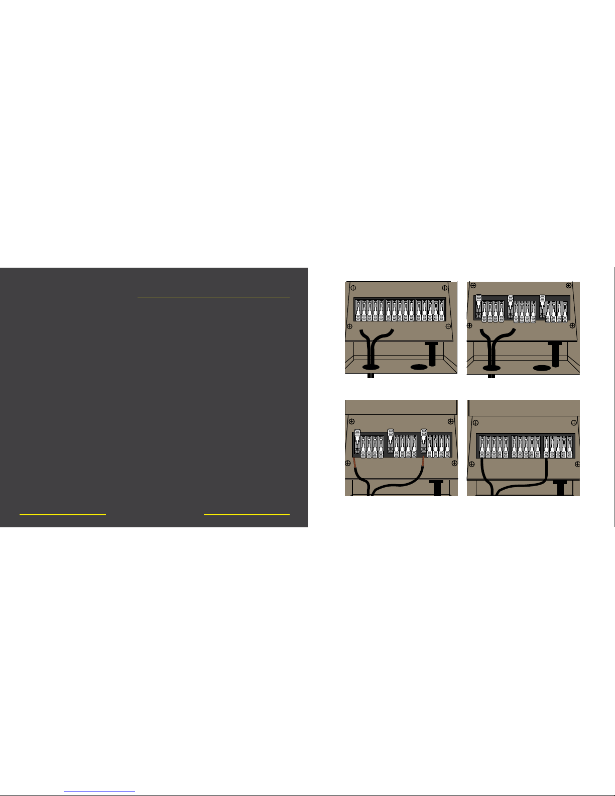
Attach all of your wires to the transformer. Using the
common and voltage terminals split each wire and t one
side into the common and one side into your desired voltage
terminal (some transformers will only have one terminal).
1. Fish the wire through wire slots and into the transformer.
2. Flip up the easy connect lever which will allow wire entry.
3. Bare the lead ends of your wires to allow metal to metal
contact within the connector.
4. Slide one side of the wire into the common terminal and one
side into the voltage terminal, then clamp both levers down onto
the wires. Check for a strong connection by rmly pulling on the
wire.
Quick Start Step 4
www.voltlighting.com
4
H
r
s
6
H
r
s
8
H
r
s
1
0
H
r
s
O
F
F
O
N
2
H
r
s
D
a
w
n
D
u
s
k
-
4
H
r
s
6
H
r
s
8
H
r
s
1
0
H
r
s
O
F
F
O
N
2
H
r
s
D
a
w
n
D
u
s
k
-
1 2
3 4
Page 10
Firmly pull each individual wire to ensure that they are all
completely secure. If you have an issue with a wire that is
not secure, try snipping the end and baring less wire at the
end before remaking your connection.
Quick Start Step 5
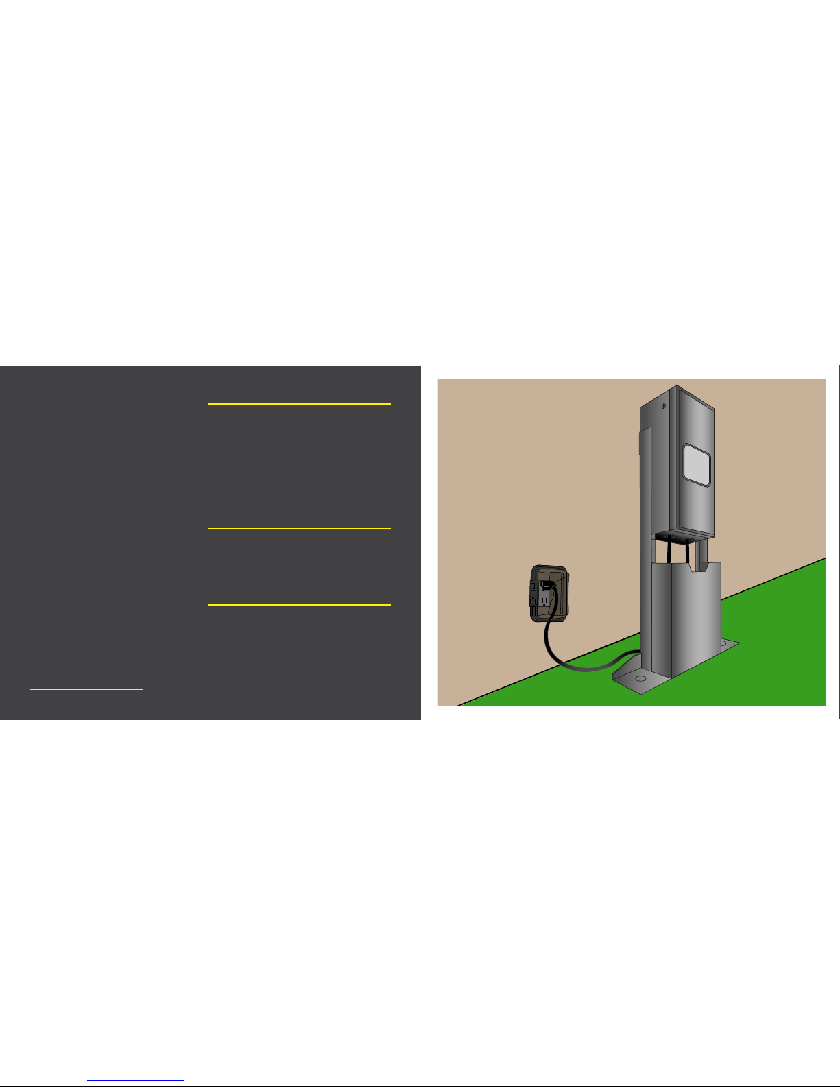
Plug in your transformer at a GFCI protected outlet with
an In-Use cover.
Quick Start Step 6
Flip the transformer’s internal breaker upward to the on
position to power on the unit.
Quick Start Step 7
www.voltlighting.com
Page 11
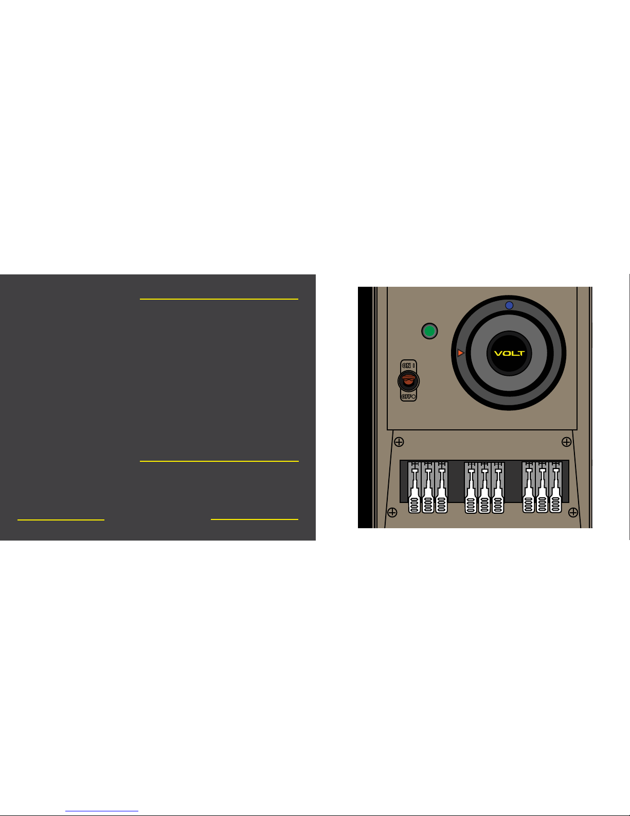
Check that both pilot lights are on inside your transformer
power unit. The main pilot light for your transformer is
green and right above the internal breaker. If it is not on,
your transformer is not receiving power. Check that the
breaker for your GFCI outlet is on. For any line voltage
issues, contact a licensed electrician.
The timer’s pilot light is blue and towards the top of the
timer. Be sure that the timer pilot light is also on to ensure
proper timer function.
Quick Start Step 8
Turn your timer clockwise to the manual “ON” setting by
aligning the word “ON” with the orange triangle on the left.
Quick Start Step 9
www.voltlighting.com
4
H
r
s
6
H
r
s
8
H
r
s
1
0
H
r
s
O
F
F
O
N
2
H
r
s
D
a
w
n
D
u
s
k
-
Page 12
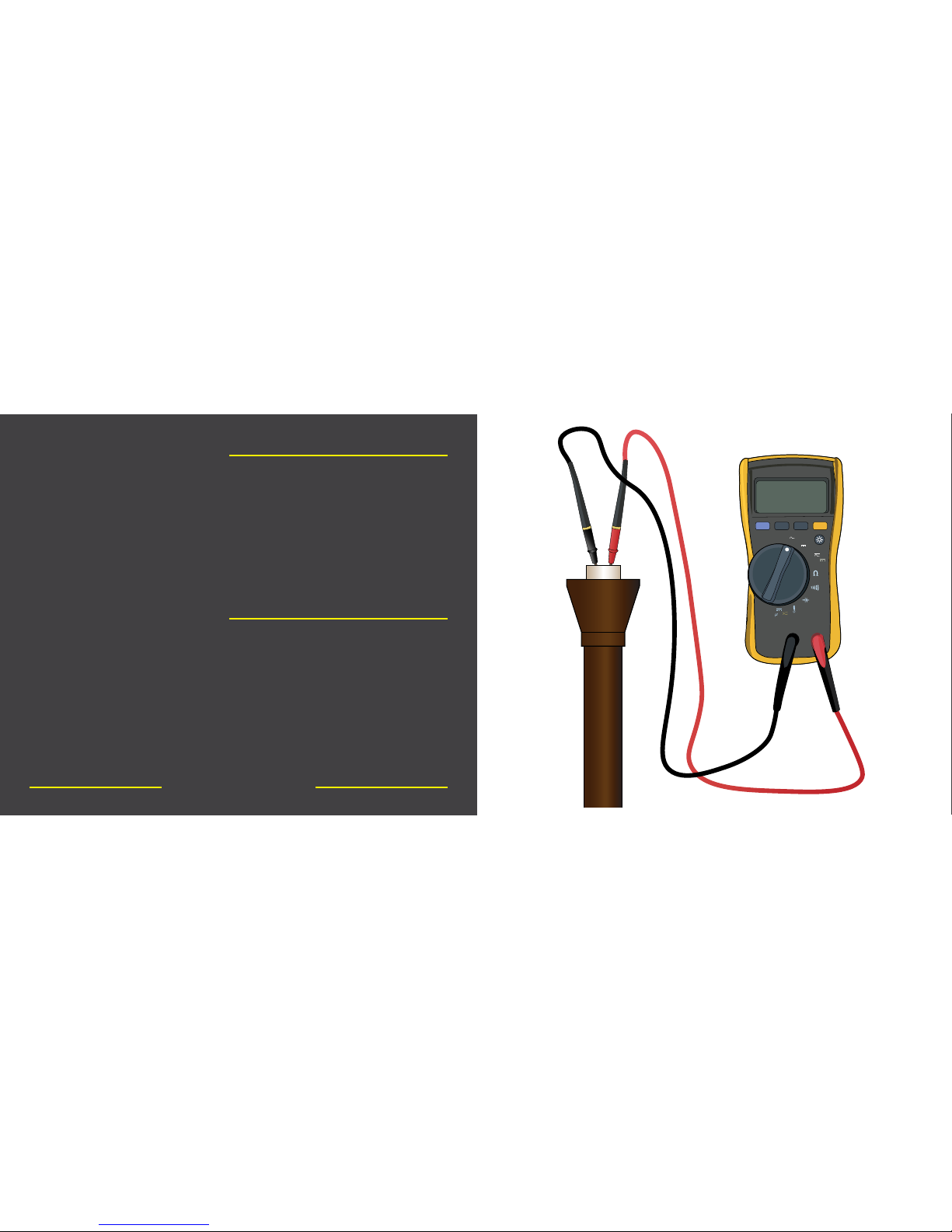
Using a volt meter, measure the voltage at your xtures by
removing the lamp and using the probes in the bulb receptacle.
Be sure that all other lamps are installed at the time of testing.
For integrated xtures, test voltage at the closest connection
point to the lighting xture. A good range is typically between
10.8 -15 volts for LED lighting xtures.
Quick Start Step 11
www.voltlighting.com
Go around and check that all of your xtures are on and
functioning properly. Flickering or xtures that aren’t powered
on could present a connection problem at the xture or lamp. If
a failed lamp is suspected, try replacing it with another that is
working in a different location. This will help you to troubleshoot
where the problem is.
Quick Start Step 10
HOLD
MIN MAX
RANGE
AUTO-V
LoZ
OFF
V
Hz
V
mV
A
COM
+
V
AC
12.00
Page 13
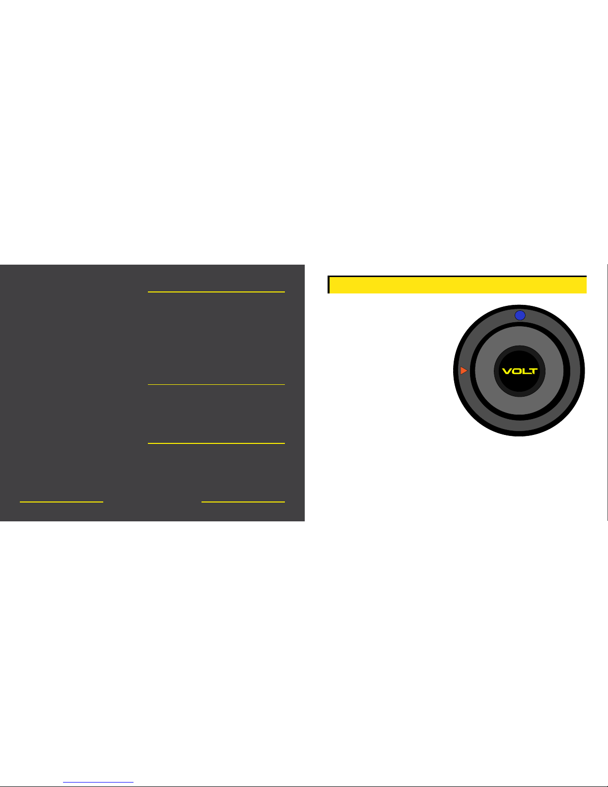
Set your timer to the desired function for everyday use.
The next page will show you in detail the various timer
functions.
Quick Start Step 13
Close the transformer door ensuring a tight seal.
Quick Start Step 14
www.voltlighting.com
If needed, you can adjust your xture voltage by using a higher
voltage at the transformer terminal.
CAUTION: When adjusting low voltage wires, be sure to unplug
your transformer prior to switching terminals
.
Quick Start Step 12
4
H
r
s
6
H
r
s
8
H
r
s
1
0
H
r
s
O
F
F
O
N
2
H
r
s
D
a
w
n
D
u
s
k
-
2 Hrs: Function that keeps lights
on for 2 hours after dusk.
4 Hrs: Function that keeps
lights on for 4 hours after dusk.
6 Hrs: Function that keeps
lights on for 6 hours after dusk.
8 Hrs: Function that keeps
lights on for 8 hours after dusk.
10 Hrs: Function that keeps
lights on for 10 hours after dusk.
OFF: Manual off function
ON: Manual on function
Dusk - Dawn: Photocell function that turns transformer on at dusk
and off at dawn.
Pilot Light: This lets you know that the timer has power and is
functioning properly. Note that it will take a few seconds to light
up.
TIMER FUNCTIONS
Page 14

15486 N. Nebraska Avenue | Lutz, FL 33549 | 1-813-978-3700
www.voltlighting.com
 Loading...