

Volt 1KTS, 1.5KTS, 2KTS, 3KTS, 4KTS User Manual
...
Solar Grid Tie Inverter
User Manua
l
1
1. Notes
This manual is an integral part of the inverter. Please read this manual carefully before installation,
operation or maintenance and it’s for future reference.
1.1 Scope
1KTS 1.5KTS 2KTS 3KTS
4KTS 5KTS 6KTS 7KTS
Please keep this manual where it will be accessible at all times.
1.2 Target Group
This manual is to be read by qualified installer and PV system user. The tasks described in this manual
must only be performed by qualified technical service personnel.
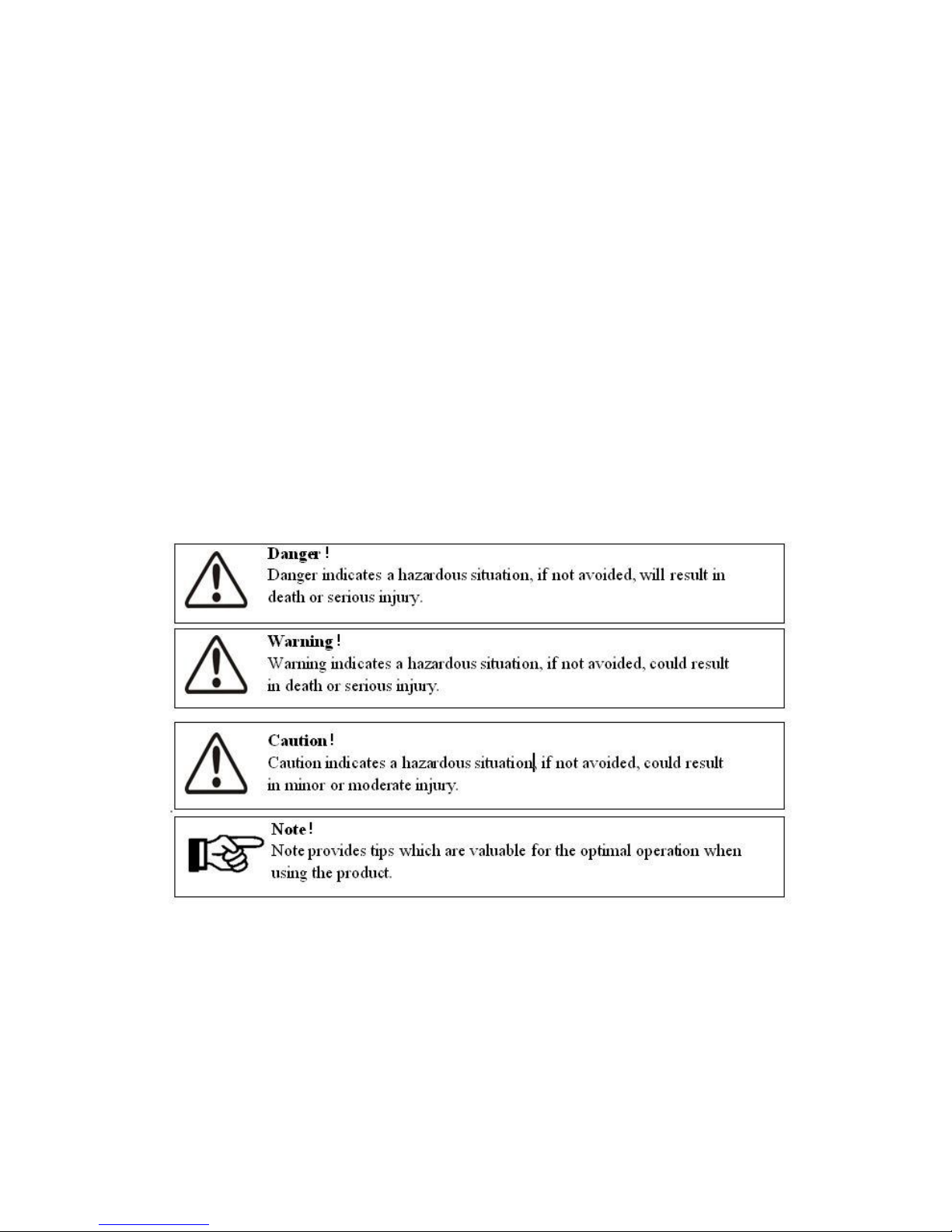
1.3 Symbols Used
Some symbols are used in this manual in order to ensure safety of p ersonal and property. Please read
the following symbols carefully.
2. Safety
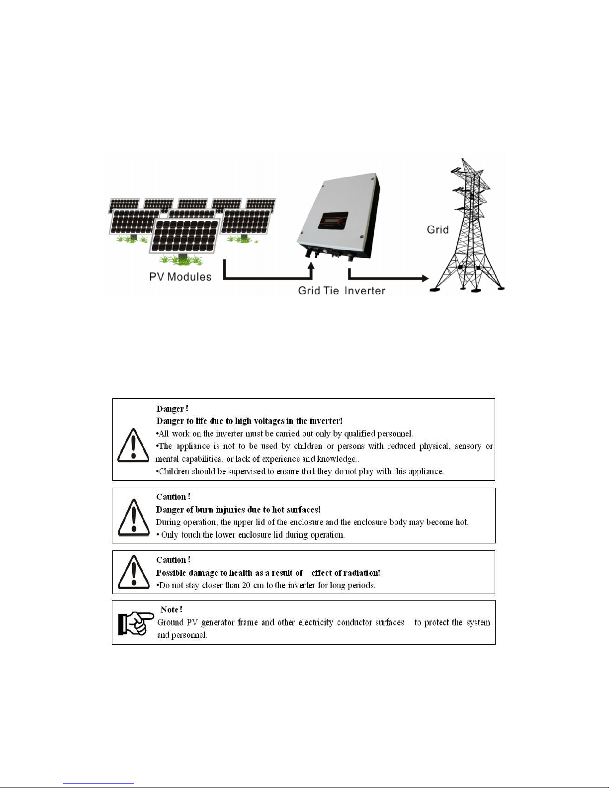
2.1 Appropriate Usage
The Series is a Solar PV inverter which converts the DC current from a PV generator into
AC current and feeds it into the public grid.
2
Figure 1 Solar PV Grid-tied System
2.2 Important Safety Instructions
3
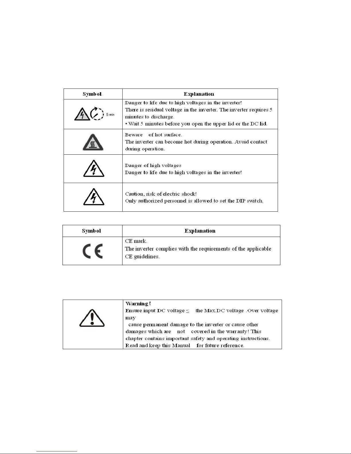
2.3 Explanation of Symbols
This section gives an explanation of all the symbols shown on the inverter and on the type label.
●Symbols on the Inverter
● Symbols on the Type Label
● Important Safety Instructions
When using the product, please read follow information below to avoid fire, lightning or other
personal injury:

4
● Before using the Series inverter, read all instructions and cautionary markings on the
Series inverter, and all appropriate sections of this guide.
●Use only a accesories recommended or sold by , otherwise may result in risk of fire, electric shock,
or injury to persons.
● To avoid risk of fire and electric shock, make sure that existing wiring is in good condition and
cables used are not undersized. Do not operate the Series inverter with damaged or substandard
wiring.
● Do not disassemble the S eries inverter. It contains no user-serviceable parts. See Warranty
for instructions on obtaining service. Attempting to service the Series inverter, the user may result
in risk of electric shock or fire and will void the warranty.
● To reduce the risk of electric shock, authorized service personnel must disconnect both AC and DC
power from the Series inverter before attempting any maintenance or cleaning or working on any
circuits connected to the Series inverter. Turning off controls alone will not reduce this risk.
● Keep away from flammable, explosive materials to avoid fire disaster.
● The installation location should not be close to humid or corrosive substance.
● To avoid electric shock, please do not disassemble the inverter as there are high-voltage
capacitances installed inside the inverter. Fatal High-voltage will remain in the inverter for 5 minutes
after its disconnection from grid or PV plant.
● To reduce the chance of short-circuits, authorized service personnel must use insulated tools when
installing or working with this equipment.
3.Introduction
3.1 Basic Features
Congratulations on your purchase of a series inverter. The Series inverter is one of the finest inverter
on the market today, incorporating state-of-the-art technology, high
reliability, and
convenient control
features.
Advanced MCU ( Microcontroller Unit) control technology.
Utilize the latest high-efficiency power component.
Optimal MPPT technology.
Advanced anti-islanding solutions.
5
Excellent protections.
IP65 protection level.
Efficiency up to 97.6%.
Total Harmonic Distortion (THD)<3%.
Safe & Reliable: transformer less design with software and hardware protection.
Friendly HMI ( Human Machine Interface).
LED status indication.
LCD display of technical data, Human-Machine interaction through press key.
RS485/RS232 communication interface.
PC remote control.
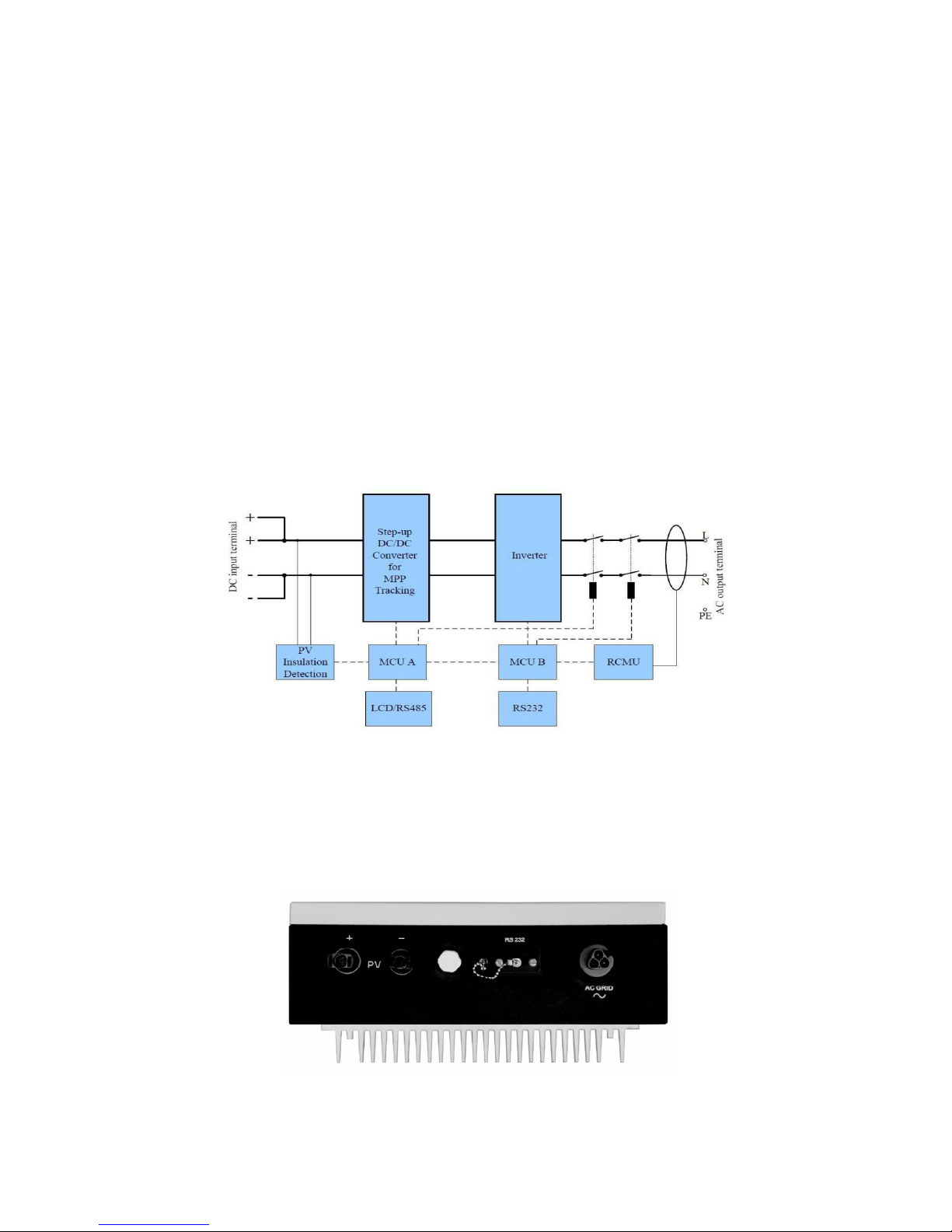
3.2 Electrical block diagram
Figure 2 Electrical block diagram
●Terminals on the inverter
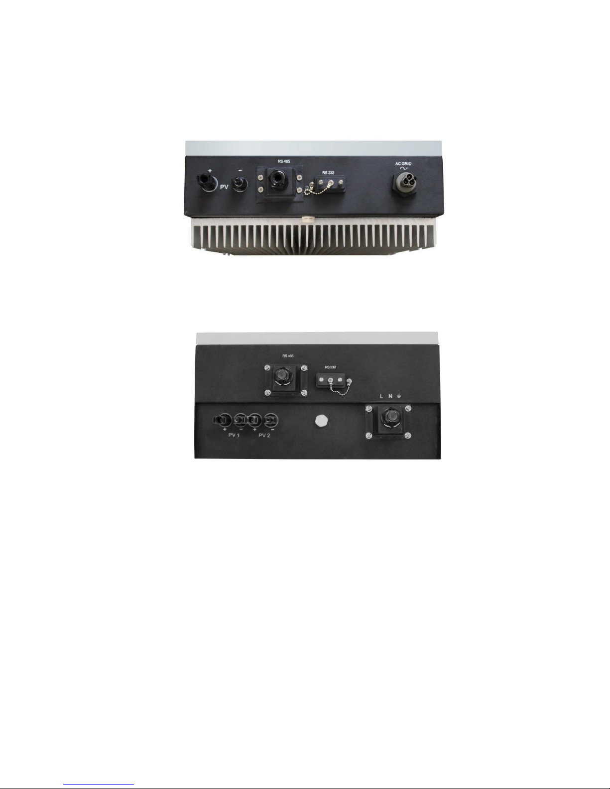
6
Figure 3 Terminals of PV inverters 1KTS/ 1.5KTS
t
Figure 4 Terminals of PV inverters 2KTS/
3KTS
Figure 5 Terminals of PV inverters 4KTS / 5KTS / 6KTS/ 7KTS
3.3 Dimensions and Weight
●Dimension
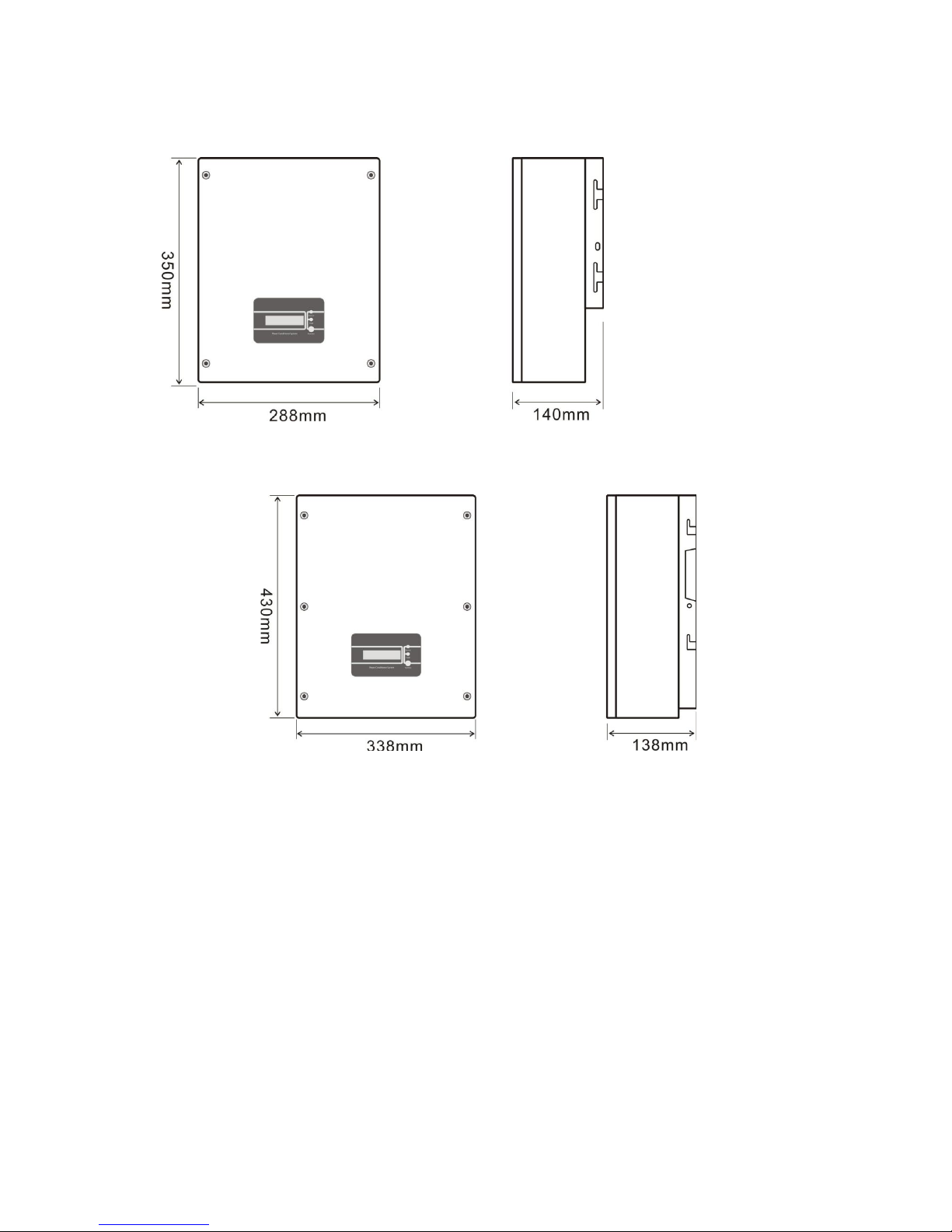
7
Figure 6 1KTS/ 1.5KTS
Figure 7 2KTS/ 3KTS
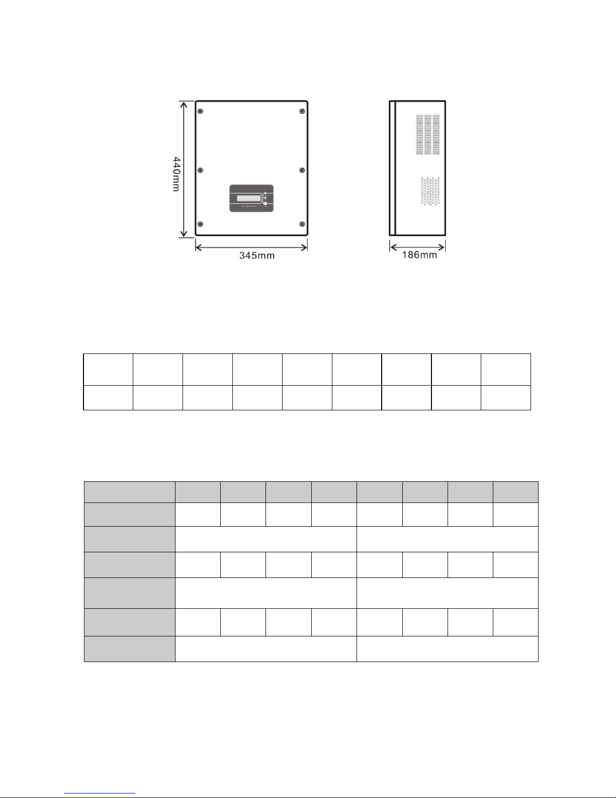
8
Figure 8 4KTS / 5KTS / 6KTS/ 7KTS
●Weight
Table 1 Weight in kilo grams, kgs
Model
1KTS 1.5KTS 2KTS 3KTS 4KTS 5KTS 6KTS 7KTS
Weight
[kgs]
11Kgs 11.5Kgs 15Kgs 15.5Kgs 21Kgs 21.5Kgs 22.5Kgs 23Kgs
4. Technical Data
4.1 Input (DC)
Model
1KTS 1.5KTS 2KTS 3KTS 4KTS 5KTS 6KTS 7KTS
Max. DC power [W] 1100
1600
2300
3200
4200
5400
6100
7000
Max. DC voltage
[V]
500
550
Max. input Current
[A]
8.8
9.7
11
13
21
26
32
37
Number of MP
P
trackers / Strings per
MPP tracker
1 / 1
1 / 2
MPPT voltage range
(at rated power) [V]
120-425
160-425
200–500
210-500
180-500
180-500
180-500
180-500
Shutdown voltage /
Start voltage [V]
70 / 100
70/100
 Loading...