

Page 1

SIGNATURE SERVER® SERVING EQUIPMENT
Hot Food Stations
Bain Marie Stations
Refrigerated Cold Stations
Non Refrigerated Cold Stations
Frost Top Stations
Entree Carts
Hot/Cold Stations
Milk Stations
Beverage Stations
Utility Stations
Cashier Stations
ENGLISH
Operator’s Manual
Thank you for purchasing this Vollrath serving equipment. Before operating the unit, read and familiarize yourself with the following operating and safety
instructions. SAVE THESE INSTRUCTIONS FOR FUTURE REFERENCE.
RegisteR youR pRoduct on-line at www.vollRath.com
Item No. 2350100-1 en Rev 08/14
Page 2

Safety PrecautionS
To ensure safe operation, read the following statements
and understand their meaning. This manual contains safety
precautions which are explained below. Please read carefully.
NOTE:
When moving or transporting this unit use caution to not damage the
electrical power cord.
lighting information (Some modelS)
If lighting is used, it is recommended that plastic coated type lamps or
equivalent are used to reduce the possibility of breakage.
WARNING
Warning is used to indicate the presence of a hazard that can
cause severe personal injury, death, or substantial property
damage if the warning is ignored.
CAUTION
Caution is used to indicate the presence of a hazard that will or
can cause minor personal injury or property damage if the caution
is ignored.
NOTE
Note is used to notify people of installation, operation, or
maintenance information that is important but not hazard-related.
For Your Safety!
These precautions should be followed at all times. Failure to follow
these precautions could result in injury to yourself and others.
To reduce risk of injury or damage to the unit:
Plug only into grounded electrical outlets matching the nameplate
rated voltage.
Do not use an extension cord with this equipment. Do not plug this
equipment into a power strip or multi-outlet power cord.
Unit should only be used in a at, level position.
ENGLISH
Unplug unit and let it cool before cleaning or moving.
Do not spray controls or outside of unit with liquids or cleaning
agents.
Unplug when not in use.
Keep unit and power cord away from open ames, electric burners
or excessive heat.
Do not operate unattended.
Closely supervise units operating in public areas and/or around
children.
Do not use food pans deeper than 4” (10 cm).
Do not operate if unit has been damaged or is malfunctioning in any
way.
Do not place any objects inside the air intake or exhaust panels.
Do not place weight on controls.
Do not operate hot well without water.
function and PurPoSe
This unit is intended and designed to keep food at proper serving
temperatures. Hot food stations are not intended or designed to cook raw
food or to reheat prepared food. Cold food stations are not intended or
designed to cool or chill food. Food must be prepared and placed in food
stations at proper serving temperatures.
unit inStallation
This unit is to be used on a at, level surface. If this unit has controls and
drains they need to be accessible at all times of operation. If the unit has a
vent the vent needs to face an open area so that air can circulate.
NOTE:
Do move the unit by pushing or pulling on the breath guard.
There must be a minimum of 24” (61 cm) of space between one side
of solid surfaces and on two sides for heating units.
There must be a minimum of 24” (61 cm) of space between the vents
and any solid surfaces for units with vents.
Sufcient airow must be allowed around the unit. Blocking the
airow could cause the unit to overheat.
oPeration
drain ValVe and acceSS door - all modelS
B
A
E
D
C
Figure 1. Drain Valve and Drain Valve Access Door
A
DRAIN VALVE ACCESS DOOR. Covers the drain opening.
B
DRAIN VALVE OPENING. Access opening for the drain
valve.
C
DRAIN VALVE. Used to empty water from the well(s).
D
DRAIN VALVE CLOSED position. When the valve is in this
position the drain is closed.
E
DRAIN VALVE OPEN position. When the valve is in this
position the drain valve is open.
WARNING
2
unPacking the equiPment and initial SetuP
Carefully remove crating or packaging materials from the unit. Dispose of
all packaging, materials in an environmentally responsible manner.
Free the power cord from its secure shipping location. It is usually coiled
inside the cabinet.
OperatOr’s Manual
Burn Hazard.
Do not touch heating surfaces, liquid, or food while
unit is heating or operating.
Hot food, steam and liquids can burn skin. Allow the hot liquid,
spillage pans and trays to cool before handling. Use gloves, mitts or
pot holders if it is necessary to handle hot pans.
Page 3
A
WARNING
Electrical Shock Hazard.
Keep water and other liquids from entering the
inside of the unit. Liquid inside the unit could cause
an electrical shock. Do not damaged power cord.
Do not over ll wells, pans or trays. Liquid could contact the
electrical components and cause a short circuit or an electrical
shock. Unplug unit before performing service, draining or removing
spillage pans and trays. Do not spray water or cleaning products.
Do not use a power cord that has been modied or damaged.
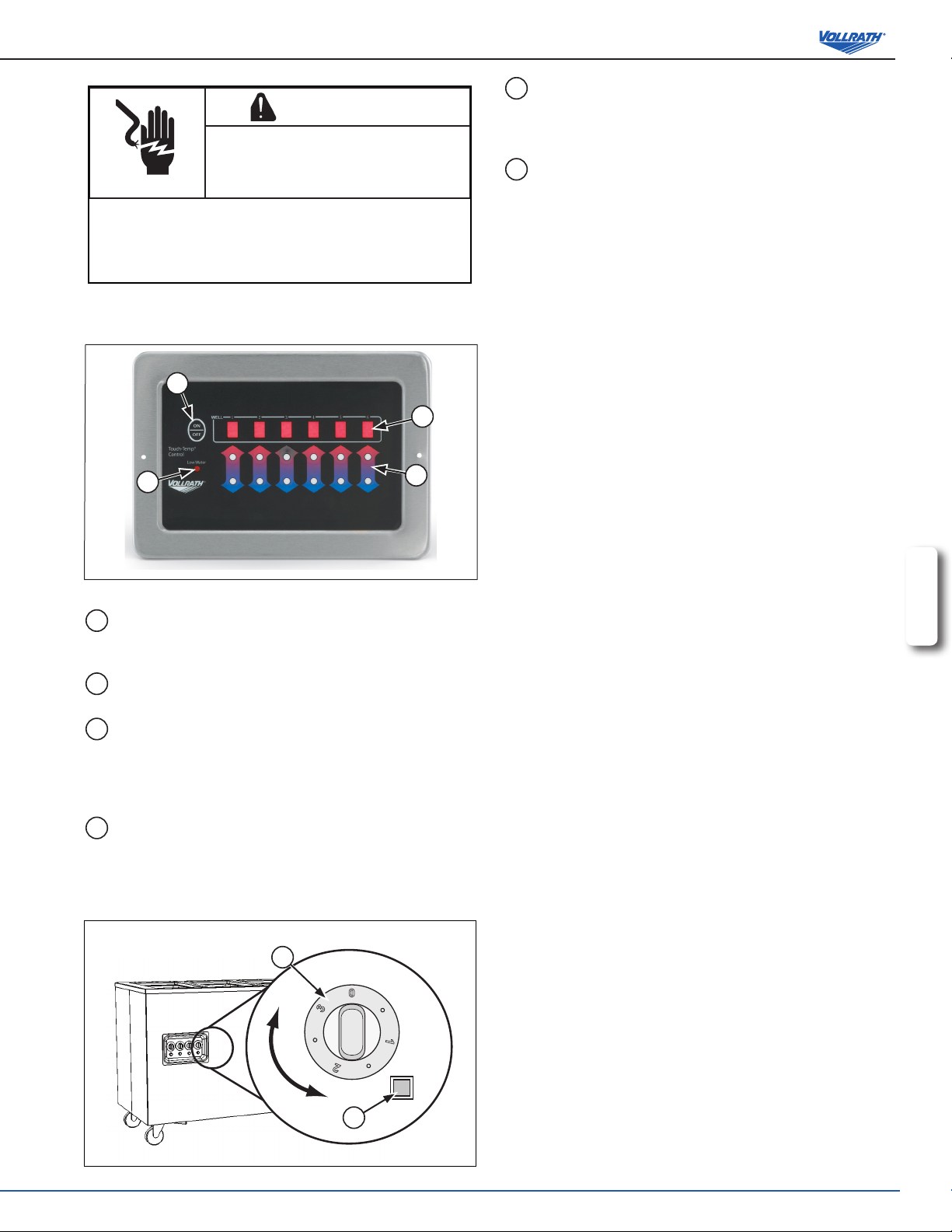
digital hot Station controlS
(The discontinued Touch Panel Control is shown in the back of this manual.)
A
B
D
C
B
hot Station oPeration
1. Open the valve access door (A) and check that the drain valve (C) is in
2. Fill each well with about 2 quarts (1.9 lt), until water level is
3. Plug electrical power cord into a grounded outlet matching the nameplate
4. Preheat the water in the wells by covering wells with empty food
5. Remove empty food containers or covers. Place containers rated for hot
6. Place covers on food containers. Leave covers on food containers unless
7. Set the heat setting switch(es) (C) to maintain proper hot holding
TEMPERATURE CONTROL dial. Used to set or adjust the
temperature of the well. The higher the number the higher the
temperature, the lower the number the lower the temperature.
The “0” position is off.
POWER light. Illuminates when the well is in the heating mode.
the closed position (D). See Figure 1.
approximately 3/8” (.95 cm) deep. Do not overll. Always maintain water
in well.
rated voltage.
containers or covers. Turn the power switch (A) to the “ON” position and
set the heat setting switch(es) (C) to the maximum setting. See Figure 2.
Or, turn the temperature control (A) to the maximum heat setting. See
Figure 3. Preheat for 45 minutes. The water will be boiling.
food that contain hot food into the preheated wells. Do not use food pans
deeper than 4” (10 cm).
serving food.
temperature for food safety. Regularly check food temperature.
ENGLISH
Figure 2. Digital Hot Station Controls
A
ON/OFF switch. Press and hold the ON/Off switch for two (2)
seconds to turn the unit On or OFF. The wells will be set to the
previously used setting.
B
WELL SETTING DISPLAY. Illuminates with the well heat
setting.
C
HEAT SETTING SWITCHES. Used to set or adjust the
temperature of the well. Push and hold arrows for each well
until the desired setting appears on the well setting display. The
“0” position is off. The heat settings range between 0 and 9.
0 = Off --- 9 = High.
D
LOW WATER light. Illuminates when the well needs water. If
the light illuminates during operation, clean fresh water must be
added to the well.
dial control hot Station controlS
A
0
3
○
○
1
○
2
NOTE:
Monitor food temperature closely for food safety. The United States
Public Health Service recommends that hot food be held at a minimum
of 140 ºF (60 ºC) to help prevent bacteria growth. Maintain correct water
level and temperature setting. Periodically remove food container and
check the water level. Add water if needed.
8. When nished using the unit. Turn the heat setting switch(es) (C) to
“0” setting, turn the power switch (A) to the “OFF” position and unplug.
See Figure 2. Or, turn the temperature control (A) to the “0” setting and
unplug. See Figure 3. When removing hot food containers from unit use
gloves, mitts or pot holders to protect hands.
9. Allow the unit and water to cool completely.
10. Open access the drain valve access door (A). See Figure 1.
11. Place a suitable container directly under the drain valve (C). Turn the
drain valve (C) to the open position (E) monitoring the ow of liquid going
into the container. Use caution to avoid spills that may create a slippery
condition. Turn drain valve (C) to the closed position (D) off before the
container is full. Dispose of the drained water. This procedure may need
to be repeated.
12. Turn drain valve (C) to the closed position (D) and close the drain valve
access door (B).
Figure 3. Manual Hot Station Controls
B
OperatOr’s Manual
3
Page 4

refrigerated WellS and froSt toP controlS and oPeration
A
NOTE:
Monitor food temperature closely for food safety. The United States
Public Health Service recommends that cold food be held at a
maximum of 41 ºF (5 ºC) to help prevent bacteria growth.
6. When nished using the unit. Turn the ON/OFF switch (A) to the
“OFF” position and unplug. See Figure 4.
7. Open access the drain valve access door (A). See Figure 1.
8. Place a suitable container directly under the drain valve (C). Turn the
drain valve (C) to the open position (E) monitoring the ow of liquid
going into the container. Use caution to avoid spills that may create
a slippery condition. Turn drain valve (C) to the closed position (D)
off before the container is full. Dispose of the drained water. This
procedure may need to be repeated.
9. Turn drain valve (C) to the closed position (D) and close the drain
valve access door (B).
Figure 4. Refrigerated Well and Frost Top Control
A
ON/OFF switch. Set switch to the up position for “ON”.
Set switch to the down position for “OFF”. The switch will
illuminate when in the “ON” position.
1. Open the valve access door (A) and check that the drain valve (C) is
in the closed position (D). See Figure 1.
2. Plug electrical power cord into a grounded outlet matching the
nameplate rated voltage.
3. Turn the ON/OFF switch (A) to the “ON” position. See Figure 4. This
unit does not have an adjustable temperature setting. Allow the unit
to run for approximately 30 minutes. For the best performance when
using ice with this unit, allow unit to run for approximately 2 hours
before adding ice. This will help the ice remain solid.
4. Place containers of properly chilled food into the pre-chilled unit.
ENGLISH
5. Regularly check the food temperature.
troubleShooting
Problem It might be caused by Course of Action
Switch does not light up when in the “ON”
position.
Unit does not get to correct temperature or
to a high temperature.
cleaning
all modelS
To maintain the appearance and increase the service life, clean your
equipment daily.
1. Turn off and unplug the unit.
2. Begin cleaning after hot well units have completely cooled or cold well
units have been drained.
3. Wipe the unit exterior with a clean damp cloth.
4. Do not use abrasive materials, scratching cleansers or souring pad to
clean the unit. These can damage the nish.
5. Thoroughly wipe off any mild soap or chemical cleaners. Residue
could corrode the surface of the unit.
Unit is not plugged in. Plug unit in.
Low or incorrect voltage to unit. Verify that voltage rating in unit matches the source voltage. If not
have qualied electrical personal install proper source voltage.
No water or incorrect water level. Add water to correct level.
4
OperatOr’s Manual
Page 5

diScontinued touch Panel control featureS and function
1
11
15
13
6
12
16
14
8
9
10
2
4
5
7
3
The discontinued touch panel control features and function are described below.
Figure 5. Discontinued Touch Panel Control
1. Electronic control panel.
2. Individual well Start/Stop switch. Push and hold to turn individual well on
and set heat level. Push again to turn well off.
3. Well indicator light. Lights when well is activated.
4. Well temperature display switch. Push and hold to display heat setting
selected for each individual well.
5. Master Start/Stop switch. Push to turn off all the wells at one time. Green
light indicates that the master switch may be used to reactivate all the
wells at the previous setting.
6. Heat setting display. Red lights indicate setting selected.
7. Clock. Used for time of day setting and Start/Stop programming.
8. Hour Set.
9. Minute Set.
10. Automatic Programming Start switch. Push to activate auto Start/Stop
Program. Clock must be set and operating to use this function.
11. Auto Start set switch.
12. Auto Stop set switch.
13. Preheat switch. Sets automatic 45 minute preheat when in automatic
mode. When used outside of automatic mode, pressing the automatic
preheat switch will give a 45 minute preheat at the high setting and then
revert to the selected temperature. Press for one second to engage.
14. Automatic heat switch. Used to set well heat setting when using auto
mode.
15. Auto start time display. Push to display start time preset.
16. Auto stop time display. Push to display stop time preset.
Control Panel Operation (Refer to Touch
Panel control diagram)
Start/Set Wells:
1. Push (2) and hold until desired heat setting (6) is displayed. (3) lights to
indicate well is on.
2. Push (4) to display heat setting for well.
3. Repeat for remaining wells.
Stop/Turn off Wells:
1. Push (2) to turn off well. (3) turns off to indicate well is off
OR
2. Push (5) to turn off all wells at once. This option allows you to
reactivate all of the wells at the previous setting by pressing (5).
Preheat Function:
1. Push (13) either before or after setting individual well. The unit will
operate on HIGH for 45 minutes and then revert to the previously
selected setting. If (4) is pushed while in pre-heat mode, (6) will
display the HIGH indicator light #9 and the light for the level previously
selected.
2. Push (13) a second time to remove the unit from preheat mode.
Set Clock:
NOTE: the clock does not need to be set for normal operation.
1. Push (8) to set hour. PM is indicated by a light in the upper right hand
corner of the window.
2. Push (9) to set minute.
Set Wells for Auto Mode:
NOTE: This can only be used with the auto START/STOP program.
1. Push (14) SET/HEAT/DISPLAY switch. “A” will appear in the left half
of the display window (7).
2. Push (2) INDIVIDUAL WELL SET/HEAT/DISPLAY switch for wells
that are to be activated at the start time. Hold until desired setting is
reached.
3. Push (14) to program desired well settings.
Temperatures may be reset by repeating this procedure. Automatic
heat settings may be set while unit is operating. Once entered, heat
settings remain until changed or the power is interrupted.
ENGLISH
OperatOr’s Manual
5
Page 6

Set Preheat in Auto Mode:
1. Push (14) SET/HEAT/DISPLAY switch. “A” will appear in the left half of
display window (7).
2. Push (13) PREHEAT. “P” will appear in the right half of display (7)
3. Repeat procedures to remove from preheat mode.
Check Auto Mode Heat Settings:
1. Push (14) SET/HEAT/DISPLAY switch. . “A” will appear in the left half of
display window (7).
2. A green light (3) will come on above each well that has been preset.
3. Push (4) below each well to view programmed setting.
4. If PREHEAT has been selected, the HEAT DISPLAY SETTING (6) will light
#9 and programmed setting.
5. Push (14) and unit will return to AUTO mode
Program Auto Start Time:
Program Auto Stop Time:
NOTE: Clock function must be set to use this feature.
1. Push (12) AUTO STOP button to clear display (7). 00:00 will appear in the
display window.
2. Push (8) to set desired hour.
3. Push (9) to set minute. The display will advance in 5-minute increments.
4. Push (10) AUTO START button. The time of day will appear in the display
window. The green stop time indicator light will ash to indicate start time
has been programmed.
The MASTER START/STOP light will come on when stop time has been
reached and the wells have turned off.
Check Auto Start/Stop Time:
1. Push (15) to see start time in display.
2. Push (16) to see stop time in display
NOTE: Clock function must be set to use this feature.
1. Push (11) AUTO SET button to clear display (7). 00:00 will appear in the
display window.
2. Push (8) to set desired hour.
3. Push (9) to set minute. The display will advance in 5-minute increments.
4. Push (10) AUTO START button. The time of day will appear in the display
window. The green start time indicator light will ash to indicate start time
has been programmed. The light will turn off when start time has been
reached.
Cancel Auto Start/Stop Time:
1. Push (11) auto set button to clear display.
2. Push (12) auto stop button to clear display.
Repeat Auto Start/Stop Times:
After unit has cycled off from the AUTO MODE, push (10) to repeat times and
heat settings. Green start and stop time indicator lights will ash
SerVice and rePair
There are no user serviceable parts within this appliance. To avoid serious injury or damage, never attempt to repair the equipment or replace a damaged power cord
yourself. Do not send equipment directly to The Vollrath Company, LLC. Please contact Vollrath Technical Service from the list below.
VOLLRATH Technical Service • 1-800-628-0832 • Email: techservicereps@vollrathco.com
When contacting Vollrath Technical Service please be ready with the item number, model number (if applicable), serial number, and proof of purchase showing the
date the unit was purchased.
Warranty Statement for the Vollrath co. l.l.c.
This warranty does not apply to products purchased for personal, family or household use, and The Vollrath Company LLC does not offer a written warranty to
purchasers for such uses.
The Vollrath Company LLC warrants each of its products listed below against defects in materials and workmanship for the applicable period provided below. All
other products manufactured or distributed by The Vollrath Company LLC are warranted against defects in materials and workmanship for a period of one year. In
all cases, the warranty runs from the date of the end user’s original purchase found on the receipt. Any damages from improper use, abuse, modication or damage
resulting from improper packaging during return shipment for warranty repair will not be covered under warranty.
Refrigeration compressors – The warranty period is 5 years.
For refrigeration compressors and the second year of the warranty on Cayenne® Heat Strips and mixers, The Vollrath Company LLC will provide the part only;
and the buyer will be responsible for all labor charges incurred in performing the repair or replacement.
Replacement parts – The warranty period is 90 days.
Warranty does not cover: Glass, Breath Guard Glass
For complete warranty information, product registration and new product announcement, visit www.vollrath.com.
The Vollrath Company, L.L.C.
1236 North 18th Street
Sheboygan, WI 53081-3201
U.S.A.
www.vollrath.com
Main Tel: 800.628.0830
Fax: 800.752.5620
Technical Services: 800.628.0832
Service Fax: 920.459.5462
Canada Service: 800.695.8560
© 2014 The Vollrath Company, L.L.C.
Item No. 2350100-1 en Rev 08/14
 Loading...