

Page 1

Model O431
OPERATORS MANUAL
Manual No. 513635 Rev.5
Page 2

Page 3

Owner’s Manual
For O431
High Capacity Floor Model
Cabinet - Pressure Soft Serve Machine
This manual provides basic information about the machine. Instructions and suggestions are
given covering its operation and care.
The illustrations and specifi cations are not binding in detail. We reserve the right to make
changes to the machine without notice, and without incurring any obligation to modify or provide new parts for machines built prior to date of change.
DO NOT ATTEMPT to operate the machine until instructions and safety precautions in this
manual are read completely and are thoroughly understood. If problems develop or questions
arise in connection with installation, operation, or servicing of the machine, contact the company at the following location:
STOELTING Ph: 800-558-5807
502 Hwy. 67
Kiel, WI 53042 Fax: 920-894-7029
© 2013 Stoelting, LLC, All Rights Reserved
Page 4

A Few Words About Safety
Safety Information
Read and understand the entire manual before
operating or maintaining Stoelting equipment.
This Owner’s Manual provides the operator with information for the safe operation and maintenance of
Stoelting equipment. There are hazards associated
with the operation of this machine. For this reason
safety is emphasized throughout the manual. To highlight specifi c safety information, the following safety
defi nitions are provided to assist the reader.
The purpose of safety symbols is to attract your attention to possible dangers. The safety symbols, and
their explanations, deserve your careful attention
and understanding. The safety warnings do not by
themselves eliminate any danger. The instructions
or warnings they give are not substitutes for proper
accident prevention measures.
If you need to replace a part, use genuine Stoelting
parts with the correct part number or an equivalent
part. We strongly recommend that you do not use
replacement parts of inferior quality.
Safety Alert Symbol:
This symbol Indicates danger, warning or caution. Attention is required in order to avoid serious personal
injury. The message that follows the symbol contains
important information about safety.
Signal Word:
Signal words are distinctive words used throughout
this manual that alert the reader to the existence and
relative degree of a hazard.
WARNING
The signal word “WARNING” indicates a potentially
hazardous situation, which, if not avoided, may result
in death or serious injury and equipment/property
damage.
CAUTION
The signal word “CAUTION” indicates a potentially
hazardous situation, which, if not avoided, may result
in minor or moderate injury and equipment/property
damage.
CAUTION
The signal word “CAUTION” not preceded by the
safety alert symbol indicates a potentially hazardous
situation, which, if not avoided, may result in equipment/property damage.
NOTICE
The signal word “NOTICE” indicates information or
procedures that relate directly or indirectly to the
safety or personnel or equipment/property.
Page 5

TABLE OF
CONTENTS
Section Description Page
1 Description and Specifi cations
1.1 Description and Specifi cations ...................................................................1
1.2 Specifi cations .............................................................................................2
2 Installation Instructions
2.1 Safety Precautions .....................................................................................3
2.2 Shipment and Transit ..................................................................................3
2.3 Machine Installation ....................................................................................3
2.4 Installing Permanent Wiring ........................................................................3
2.5 Mix Pump ....................................................................................................4
A. Mix Pump Hose Installation..................................................................................4
B. Mix Pickup Hose Installation ................................................................................4
C. Mix Low Level Indicator Adjustment .....................................................................6
3 Initial Set-Up and Operation
3.1 Operator’s Safety Precautions ...................................................................7
3.2 Operating Controls and Indicators ..............................................................7
3.3 Disassembly of Machine Parts ...................................................................9
A. Disassembly of Front Door ...................................................................................9
B. Disassembly of Auger ..........................................................................................9
3.4 Cleaning Disassembled Parts ....................................................................10
3.5 Sanitizing Machine Parts ............................................................................10
3.6 Cleaning the Machine .................................................................................10
3.7 Assembling Machine ..................................................................................10
3.8 Sanitizing ....................................................................................................11
3.9 Initial Freeze Down and Operation .............................................................12
A. Adding Mix ...........................................................................................................12
B. Preparing the IntelliTec Control ............................................................................12
C. Initial Freeze Down ..............................................................................................12
D. Adjusting the IntelliTec Control .............................................................................12
E. Serving Product....................................................................................................13
3.10 Normal Freeze Down and Operation ..........................................................13
3.11 Mix Information ...........................................................................................13
3.12 Operation of Mix Pump ...............................................................................14
3.13 Mix Pump Cleaning ....................................................................................14
3.14 Disassembly and Inspection of Removable Parts ...................................... 15
Page 6

Section Description Page
4 Maintenance and Adjustments
4.1 Machine Adjustment ...................................................................................17
4.2 Product Consistency Adjustment ................................................................17
4.3 Locking the Control Panel ..........................................................................17
4.4 Obtaining Readings and Modifying Settings (Service Personnel Only) ......17
4.5 Readings (Service Personnel Only) ...........................................................18
4.6 Adjustments (Service Personnel Only) .......................................................19
4.7 Other Settings (Service Personnel Only) ....................................................19
4.8 Overrun Adjustment ....................................................................................20
4.9 Mix Pump Hose Reposition ........................................................................21
4.10 Mix Pump Hose Replacement ....................................................................21
4.11 Cab Temperature Adjustment .....................................................................22
4.12 Drive Belt Tension Adjustment ....................................................................22
4.13 Condenser Cleaning (Air-Cooled Machines) ..............................................23
4.14 Preventative Maintenance ..........................................................................23
4.15 Extended Storage .......................................................................................23
5 Troubleshooting
5.1 Error Codes ................................................................................................25
5.2 Troubleshooting - Error Codes ...................................................................25
5.3 Troubleshooting - Machine .........................................................................27
5.4 Troubleshooting - Mix Pump .......................................................................28
6 Replacement Parts
6.1 Brushes, Decals and Lubrication ................................................................31
6.2 Spigot Extension .........................................................................................31
6.3 Auger Shaft and Faceplate Parts ...............................................................32
6.4 Cab Tubing Assembly .................................................................................33
Page 7
SECTION 1
DESCRIPTION AND SPECIFICATIONS
1.1 DESCRIPTION
The Stoelting O431 fl oor model machine is pressure fed.
The machine is equipped with fully automatic controls to
provide a uniform product. The machine is designed to
operate with almost any type of commercial soft-serve
or non-dairy mix available, including ice milk, ice cream,
yogurt, and frozen dietary desserts.
This manual is designed to assist qualifi ed service per-
sonnel and operators in the installation, operation and
maintenance of the Stoelting O431 pressure machine.
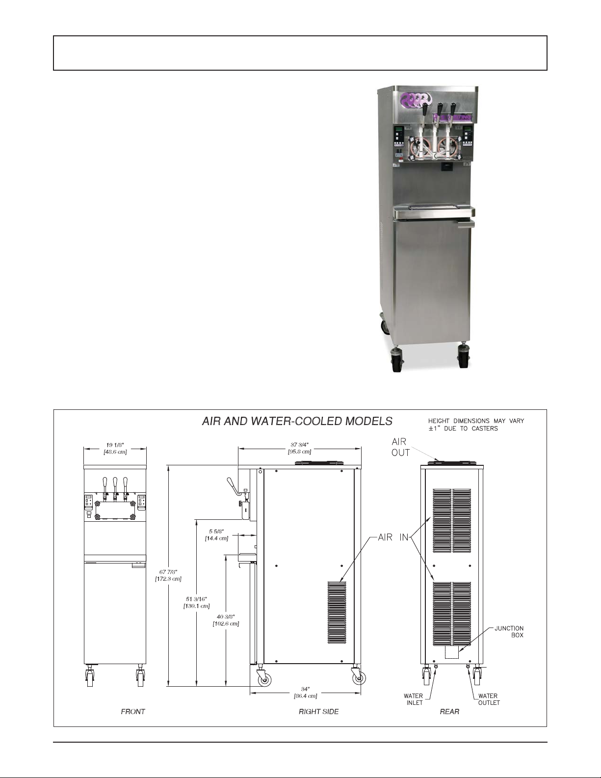
Figure 1-1 Model O431 Freezer
Owner’s Manual #513635 Rev.5 1 O431B Model Machines
Page 8

1.2 SPECIFICATIONS
Model O431B
Dimensions Machine with crate
width 19-1/8’’ (48,6 cm) 27’’ (68,6 cm)
height 67-7/8’’ (172,4 cm) 78’’ (198,1 cm)
depth 37-3/4’’ (95,9 cm) 48’’ (121,9 cm)
Weight 500 lbs (226,7 kg) 650 lbs (294,8 kg)
Electrical 1 Phase, 208-240 VAC, 60Hz
Air Cooled Water Cooled
running amps
connection type
International Option 1 Phase, 220-240 VAC, 50Hz or 3 Phase, 380-415 VAC, 50Hz
Compressor 15,000 Btu/hr Scroll™ Compressor
Drive Motor Two - 3/4 hp
Air Flow Air cooled units require 3” (7,6 cm) air space on both sides and back.
Plumbing Fittings Water cooled units require 1/2” N.P.T. water and drain fi ttings.
Hopper Volume Two - 5.5 gallons (20,82 liters)
Freezing Cylinder
Volume
17A 15A
NEMA L6-30P NEMA L6-30P
Two - 1 gallon (3,79 liters)
Owner’s Manual #513635 Rev.5 2 O431B Model Machines
Page 9
SECTION 2
INSTALLATION INSTRUCTIONS
2.1 SAFETY PRECAUTIONS
Do not attempt to operate the machine until the safety
precautions and operating instructions in this manual are
read completely and are thoroughly understood.
Take notice of all warning labels on the machine. The labels have been put there to help maintain a safe working
environment. The labels have been designed to withstand
washing and cleaning. All labels must remain legible for
the life of the machine. Labels should be checked periodically to be sure they can be recognized as warning labels.
If danger, warning or caution labels are needed, indicate
the part number, type of label, location of label, and quantity
required along with your address and mail to:
STOELTING, INC.
ATTENTION: Customer Service
502 Hwy. 67
Kiel, Wisconsin 53042
2.2 SHIPMENT AND TRANSIT
The machine has been assembled, operated and inspected
at the factory. Upon arrival at the fi nal destination, the
entire machine must be checked for any damage which
may have occurred during transit.
With the method of packaging used, the machine should
arrive in excellent condition. THE CARRIER IS RESPONSIBLE FOR ALL DAMAGE IN TRANSIT, WHETHER
VISIBLE OR CONCEALED. Do not pay the freight bill
until the machine has been checked for damage. Have
the carrier note any visible damage on the freight bill. If
concealed damage and/or shortage is found later, advise
the carrier within 10 days and request inspection. The
customer must place a claim for damages and/or shortages in shipment with the carrier. Stoelting, Inc. cannot
make any claims against the carrier.
B. Install the four casters. Turn the threaded end
into the machine until no threads are showing. T o
level, turn out casters no more than 1/4” maximum,
then tighten all jam nuts.
C. The machine must be placed in a solid level
position.
NOTE
Accurate leveling is necessary for correct drainage
of freezing cylinder and to insure correct overrun.
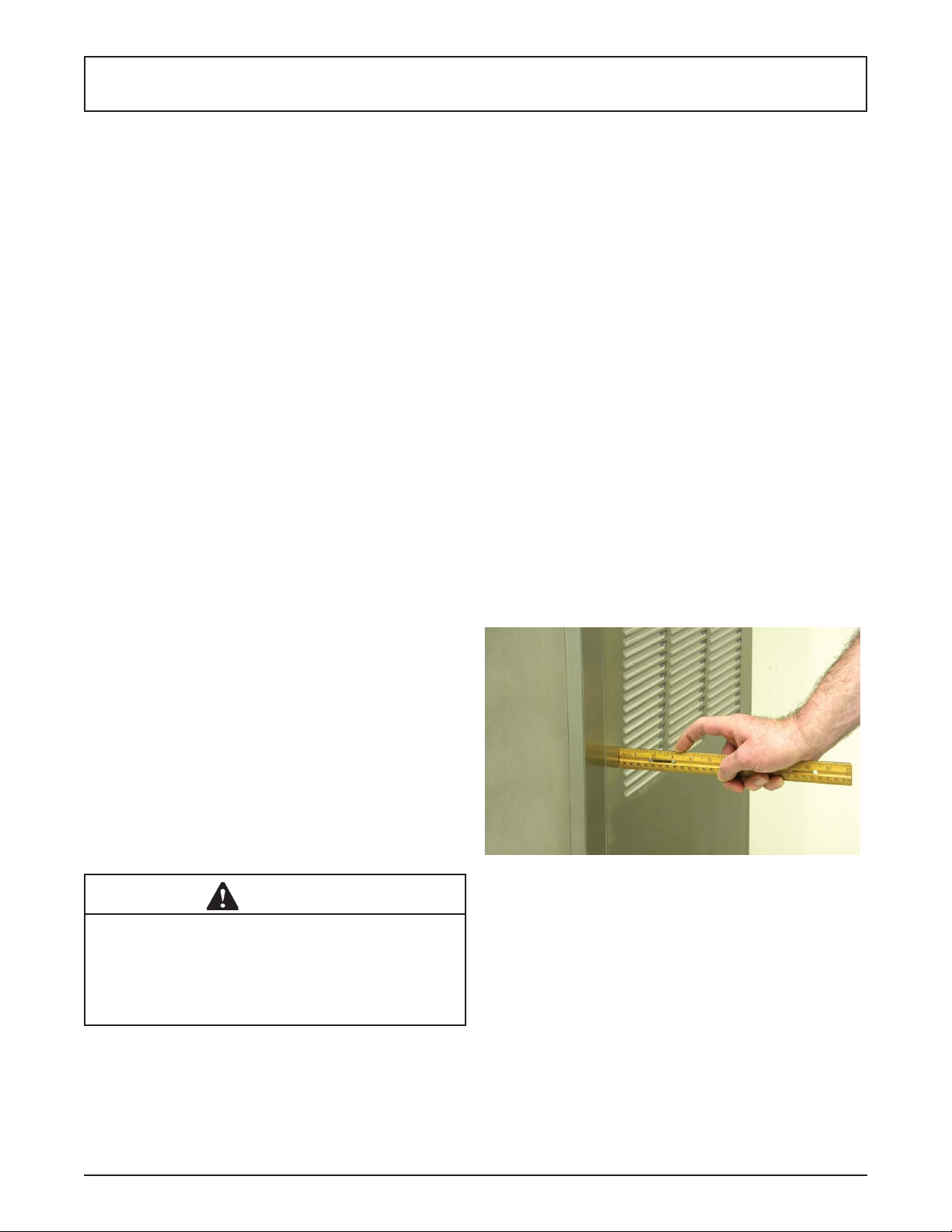
D. Machines with air-cooled condensers require 3”
(7,6 cm) air space on both sides and back for
proper circulation. (Fig. 2-1)
E. Machines that have a water-cooled condenser
require 1/2” NPT supply and drain fi ttings.
F. In air-cooled machines, use a voltmeter to
measure incoming voltage. If the supply voltage
is 215 or less, then the buck-boost transformer
must be connected to the fan motor. Refer to the
wiring diagram located behind the header panel
to connect.
NOTE
Supply voltage must be checked to make sure the
fan motor operates properly.
2.3 MACHINE INSTALLATION
Figure 2-1 Space and Ventilation Requirements
WARNING
Installation must be completed by a qualifi ed
electrician/refrigeration specialist.
Incorrect installation may cause personal injury,
severe damage to the machine and will void factory warranty.
Installation of the machine involves moving the machine
close to its permanent location, removing all crating, setting in place, assembling parts, and cleaning.
A. Uncrate the machine.
Owner’s Manual #513635 Rev.5 3 O431B Model Machines
2.4 INSTALLING PERMANENT WIRING
If permanent wiring is required by local codes, the following procedure must be performed:
A. Refer to the nameplate on the side panel of the
machine for specifi c electrical requirements. Make
sure the power source in the building matches
the nameplate requirements.
B. Remove the back panel and the junction box
cover located at the bottom of the machine.
C. Install permanent wiring according to local code.
Page 10
6” (15cm)
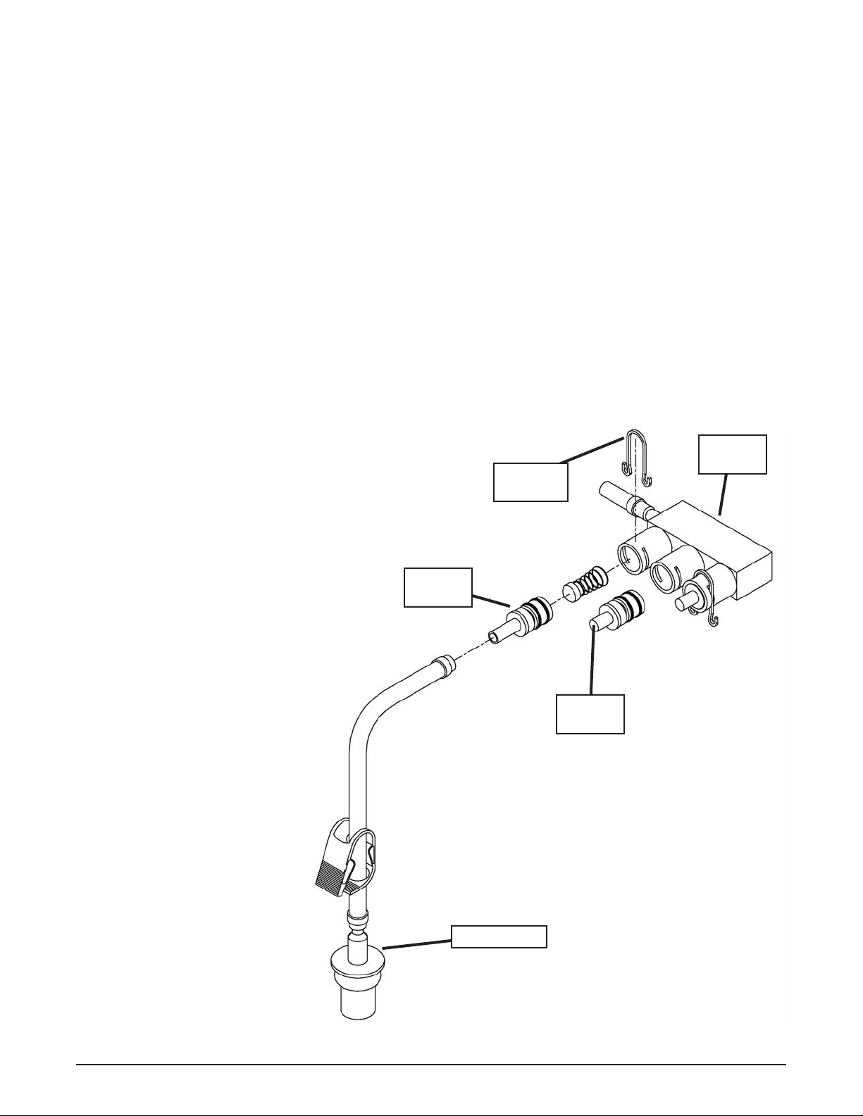
Figure 2-2 Mix Hose Installation
2.5 MIX PUMP
A. MIX PUMP HOSE INSTALLATION
Follow the steps below to install the mix pump hose in
the cabinet part of the machine.
1. Turn the mix pump on. The switch is located at
the top of the cabinet.
2. Feed one end of the mix pump hose into the
entering or pickup hose side (left) of black cover
(Fig 2-2).
NOTE
Feed the tube into the clamp so the natural curve of
the tube is towards the outside of the black cover.
This prevents the hose from looping around the
black cover twice.
3. Gently push the hose into the black cover until it
begins to feed.
4. Allow the hose to feed itself through the pump
until about 6” (15cm) remains on the entering
side.
5. Turn the pump off.
6. Connect the mix pump hose to the elbow fi tting
(located on the left side of the mix line manifold)
using a small hose clamp. Be careful not to twist
the mix hose.
7. Turn the pump on.
8. Allow the remaining 6” (15cm) of tubing to feed
through pump until the hose adapter prevents
further feeding.
9. Turn the pump off.
CAUTION
Risk of Product Damage
Air/Mix Tee must remain below the black cover
clamp. If the T ee is above the pump, mix may drain
into the air compressor resulting in pump damage.
10. Connect the free end of the mix pump hose to
the 3-way Tee (Fig. 2-3). When all connections
are complete, the 3-way Tee must be lower than
the black pump housing.
B. MIX PICKUP HOSE INSTALLATION
The O431 machine may be connected to the standard mix
container or up to three prepacked mix bags. Follow the
instructions below that match your confi guration.
Standard Connection:
1. Connect a 2” (5cm) length of 3/8” (9,5mm) ID
plastic food grade tubing to the mix pickup
assembly. Secure with hose clamps. Place the
assembly through the hole in the cover and install
the retaining clip.
Owner’s Manual #513635 Rev.5 4 O431B Model Machines
Page 11
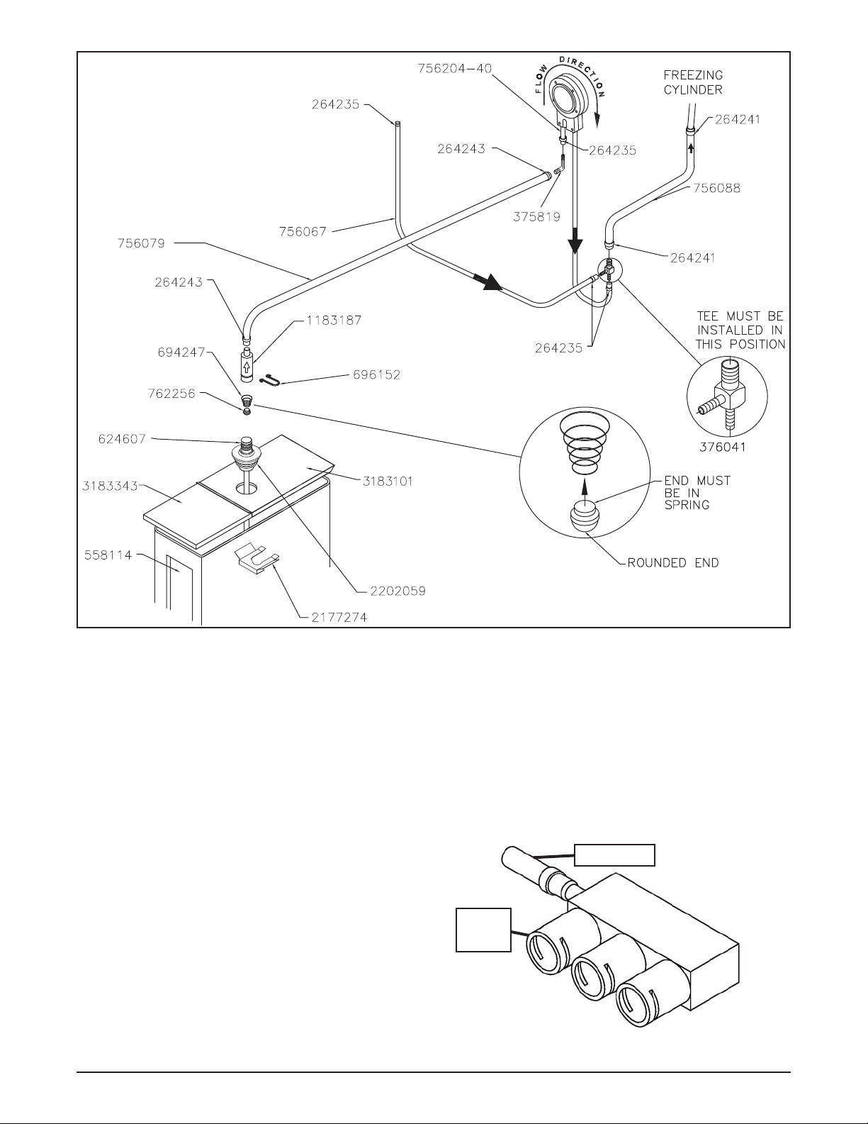
Figure 2-3 Mix Pump Connections for Standard Mix Container
2. Connect the free end of the tubing to the mix check
valve. Observe the direction of the check valve
fl ow arrow. Secure with a hose clamp. Connect a
24” (61cm) length of 3/8” (9,5mm) ID plastic food
grade tubing to the free end of the check valve
and secure with a hose clamp.
3. Connect the elbow fi tting to the free end of the
tubing. Connect the opposite end of the elbow
to 1/4” ID tan tubing on the left side of the pump
head. Secure with hose clamps (Fig. 2-3).
When Using Bag Connection System (BCS) with Three
Bags (optional kit #2183987):
The position of the three bags in the mix container is
important. The bag that is connected nearest the outlet
of the manifold will drain last and should be placed at
the back of the mix container. The mix low level indicator
relies on proper bag placement.
1. Connect 3/8” (9,5mm) ID plastic food grade tubing
to a bag adapter. Secure with hose clamps.
Owner’s Manual #513635 Rev.5 5 O431B Model Machines
2. Slide the hose clip over free end of 3/8” (9,5mm)
ID plastic food grade tubing. Attach the free end
of the tubing to a manifold adapter. Secure with
a large hose clamp or equivalent.
3. Push the manifold adapter with spring and valve
into the left port (nearest the manifold outlet) of
the mix inlet manifold and secure with a retaining
clip. (Fig. 2-5).
Mix Outlet
Drains
Last
Figure 2-4 BCS Mix Inlet Manifold
Page 12
4. Repeat steps 1 to 3 for the middle port and for
the right port of the mix inlet manifold.
5. Place three mix bags into the mix container.
6. Connect the bag adapter attached to the left side
of the manifold (closest to the mix outlet) to the
mix bag in the back of the mix container.
7. Connect the bag adapter attached to the middle
of the manifold to the mix bag in the middle of
the mix container.
8. Connect the bag adapter attached to the right
side of the manifold (farthest from the mix outlet)
to the mix bag in the front of the mix container.
When Using Bag Connection System (BCS) with One
or Two Bags (optional kit #2183987):
When connecting one or two bags, the manifold adapters must be installed closest to the manifold outlet and
the manifold plug(s) must be placed farthest from the
manifold outlet.
1. Connect 3/8” (9,5mm) ID plastic food grade tubing
to a bag adapter. Secure
with hose clamps.
2. Slide the hose clip
over the free end of
the tubing. Attach the
free end of the tubing
to a manifold adapter.
Secure with a large hose
clamp.
3. Push the manifold
adapter with spring and
valve into the left port
(nearest the manifold
outlet) of the mix inlet
manifold and secure
with retaining clip. (See
Figure 2-5).
4. If using two mix bags,
repeat steps 1 to 3 for
the middle port.
5. Install a manifold plug
into each empty inlet and
secure with a retaining
clip.
6. Place the mix bag(s) into
the mix container.
7. Connect the bag adapter
attached to the left side
of the manifold (closest
to the mix outlet) to the
mix bag in the back of
the mix container.
Manifold
Adapter
C. MIX LOW LEVEL INDICATOR ADJUSTMENT
The sensitivity of the “Mix Low” indication that displays on
the control panel can be adjusted to operator preference.
If more advanced notice of low mix is required, loosen the
black adjustment knobs located on the sensor brackets
at the back of the machine cabinet and slide the bracket
upwards. If the “Mix Low” message appears while there
is still suffi cient mix in the container, slide the bracket
downward. Be sure to tighten the adjustment knobs after
properly positioning the sensor.
Mix Inlet
Retaining
Clip
Manifold
Plug
Bag Adapter
Manifold
Figure 2-5 Bag Connection System (Optional)
Owner’s Manual #513635 Rev.5 6 O431B Model Machines
Page 13
SECTION 3
INITIAL SET-UP AND OPERATION
3.1 OPERATOR’S SAFETY PRECAUTIONS
SAFE OPERATION IS NO ACCIDENT; observe these
rules:
A. Know the machine. Read and understand the
Operating Instructions.
B. Notice all warning labels on the machine.
C. Wear proper clothing. Avoid loose fi tting garments,
and remove watches, rings or jewelry that could
cause a serious accident.
D. Maintain a clean work area. Avoid accidents by
cleaning up the area and keeping it clean.
E. Stay alert at all times. Know which switch, push
button or control you are about to use and what
effect it is going to have.
F. Disconnect power for maintenance. Never
attempt to repair or perform maintenance on the
machine until the main electrical power has been
disconnected.
G. Do not operate under unsafe operating conditions.
Never operate the machine if unusual or excessive
noise or vibration occurs.
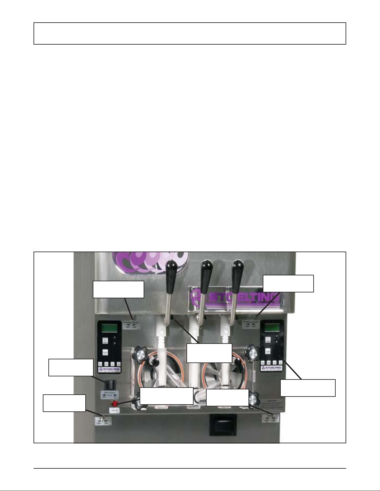
3.2 OPERATING CONTROLS AND INDICATORS
Before operating the machine, it is required that the operator know the function of each operating control. Refer
to Figure 3-1 for the location of the operating controls on
the machine. For the information regarding error codes
displayed on the control panel, refer to the troubleshooting
section of this manual.
A. MAIN FREEZER POWER SWITCH
The Main Freezer Power switch is a two position rocker
switch that supplies power to the IntelliT ec control, freezing cylinder circuits lower cabinet refrigeration system.
When the switch is placed in the ON position, the cabinet
refrigeration system will run until the preset temperature
is reached; then it will cycle ON and OFF to maintain that
temperature. Power to the freezing cylinders can then be
controlled with the Freezing Cylinder OFF/ON switch.
B. FREEZING CYLINDER OFF/ON SWITCH
The Freezing Cylinder OFF/ON switch is a two position
toggle switch used to supply power to each freezing cylinder control circuit. When the switch is in the OFF position,
the freezing cylinder’s refrigeration system and auger will
not operate. When the switch is in the ON position, the
machine will be operational.
Main Freezer
Power Off/On
Pump Power
Off/On
Freezing
Cylinder Off/On
Dispense
Rate Adjustor
Cab Off
Indicator Light
Figure 3-1 Machine Controls
Pump Power
Off/On
Freezing
Cylinder Off/On
IntelliT ec Control
(See Figure 3-2)
Owner’s Manual #513635 Rev.5 7 O431B Model Machines
Page 14

C. SPIGOT SWITCH
The spigot switch is mounted to the spigot cam assembly
behind the header panel. When the spigot is opened to
dispense product, the spigot switch opens and the “Serve
Mode” begins.
D. DISPENSE RATE ADJUSTOR
The dispense rate adjustor is located under the header
panel, to the immediate right of each spigot handle. Turning
the knob counterclockwise will decrease the dispense rate.
E. CAB OFF INDICATOR LIGHT
A fl ashing light indicates the Main Freezer Power Switch
is in the OFF position; no refrigeration is being supplied
to the cab. Place the Main Freezer Power switch in the
ON position for cab refrigeration.
F. PUMP SWITCH
The pump motor switch is the toggle switch located in
the upper left-hand side of the refrigerated cab. When
the switch is placed in the OFF position, the pump will
not run. When the switch is placed in the ON position,
the pump will run until the preset pressure is reached. It
then cycles on and off as product is drawn to maintain
that pressure.
G. PUSH TO FREEZE BUTTON
The PUSH TO FREEZE button is a snap switch used to
initiate “Serve Mode”.
NOTE
After the PUSH TO FREEZE button is pressed,
the drive motor starts. After a 3-second delay, the
compressor will start.
H. LEDS
The membrane switch (touchpad) features two lights: a
green LED and an amber LED. The green LED is lit during “Serve Mode”. During freeze down, it is not lit. When
product consistency approaches 75% in the freezing
cylinder, the green LED fl ashes. The amber LED is on
during all other modes. Both LEDs alternatively fl ash if
an error occurs or if the freezing cylinder is off.
I. CLEAN BUTTON
The CLEAN button is a snap switch. When the button is
pressed, the freezing cycle stops and the drive motor will
start. A CLEAN message will display on the LCD screen
along with a 5-minute countdown timer. To exit the CLEAN
mode, turn the Freezing Cylinder OFF/ON switch to the
OFF position or press the CLEAN button again. If the
machine is left in CLEAN for more than 20 minutes, an
error code (E4) will be displayed on the display panel.
Place the Freezing Cylinder OFF/ON switch in the OFF
position and back in the ON position to clear this error.
J. DRIVE MOTOR OVERLOAD
The internal drive motor overload will trip if the drive
motor is overloaded. It will reset after approximately 1012 minutes. If the drive motor continues to trip, refer to
Troubleshooting in Section 5.
K. MIX LOW LIGHT INDICATOR
A MIX LOW message will appear on the LCD display to
alert the operator of a low mix condition. The message
will display when there is approximately one gallon of
mix left in the mix container or when one bag of the Bag
Connection System (BCS) is empty . When the MIX LOW
message is displayed, refi ll the container or replace a
bag immediately.
L. MENU NAVIGATION BUTTONS
The Menu Navigation Buttons allow the user to display
information regarding the machine’s status of operation
as well as adjust product consistency (Fig. 3-2).
Selection Button (SEL) The SEL button is used in
combination with the up arrow button to enter into
the settings of the IntelliT ec control. This button is
also used to navigate through the control settings
menu.
Set Button (SET) The SET button is used to save
a change made to the product consistency setting.
It is also used to save changes when modifying
control settings.
Left Arrow Button (
pressed for 5 seconds, the display will remain lit.
T o turn the light off, press the left arrow button for
5 seconds. The left arrow button is used primarily
to navigate through the control settings.
Up Arrow Button () After pressing the SET
button, the up arrow button will change the value
of the product consistency setting. This button
is used primarily to navigate through the control
settings.
) If the left arrow button is
Push to Freeze
Green LED
Amber LED
Clean Button
SEL Button
SET Button
Left Arrow Button
Up Arrow Button
Figure 3-2 IntelliTec Control
Owner’s Manual #513635 Rev.5 8 O431B Model Machines
Page 15

3.3 DISASSEMBLY OF MACHINE PARTS
WARNING
Moving machinery can grab, mangle and dismember. Place the Main Freezer Power Of f/On switch in
the OFF position before disassembling for cleaning
or servicing.
Before using the machine for the fi rst time, complete
machine disassembly, cleaning and sanitizing procedures need to be followed. Routine cleaning intervals
and procedures must comply with the local and state
health codes. Inspection for worn or broken parts should
be made at every disassembly of the machine. All worn
or broken parts should be replaced to ensure safety to
both the operator and the customer and to maintain good
machine performance and a quality product. Check the
wear line on the auger fl ights on a regular basis (Fig.
3-3) and replace as needed. Frequency of cleaning must
comply with the local health regulations.
Figure 3-4 Removing O-Ring
6. Remove all o-rings from parts by fi rst wiping off
the lubrication using a clean towel. Then squeeze
the o-ring upward to form a loop (Fig. 3-4). Roll
the o-ring out of the groove.
CAUTION
Do not use any type of sharp object to remove the
o-rings.
Wear Line
Figure 3-3 Auger Flight Wear
T o disassemble the machine, refer to the following steps:
A. DISASSEMBLY OF FRONT DOOR
1. Turn the Main Freezer Power Off/On switch to
the OFF position.
2. Remove the knobs on the front door.
3. Remove the front door by pulling it off the studs.
4. Remove the air bleed valve by unscrewing the
knob while holding the valve stem from behind.
Remove the compression spring and push the
air bleed valve through the rear of the front door.
5. Remove the spigots through the bottom of the
front door.
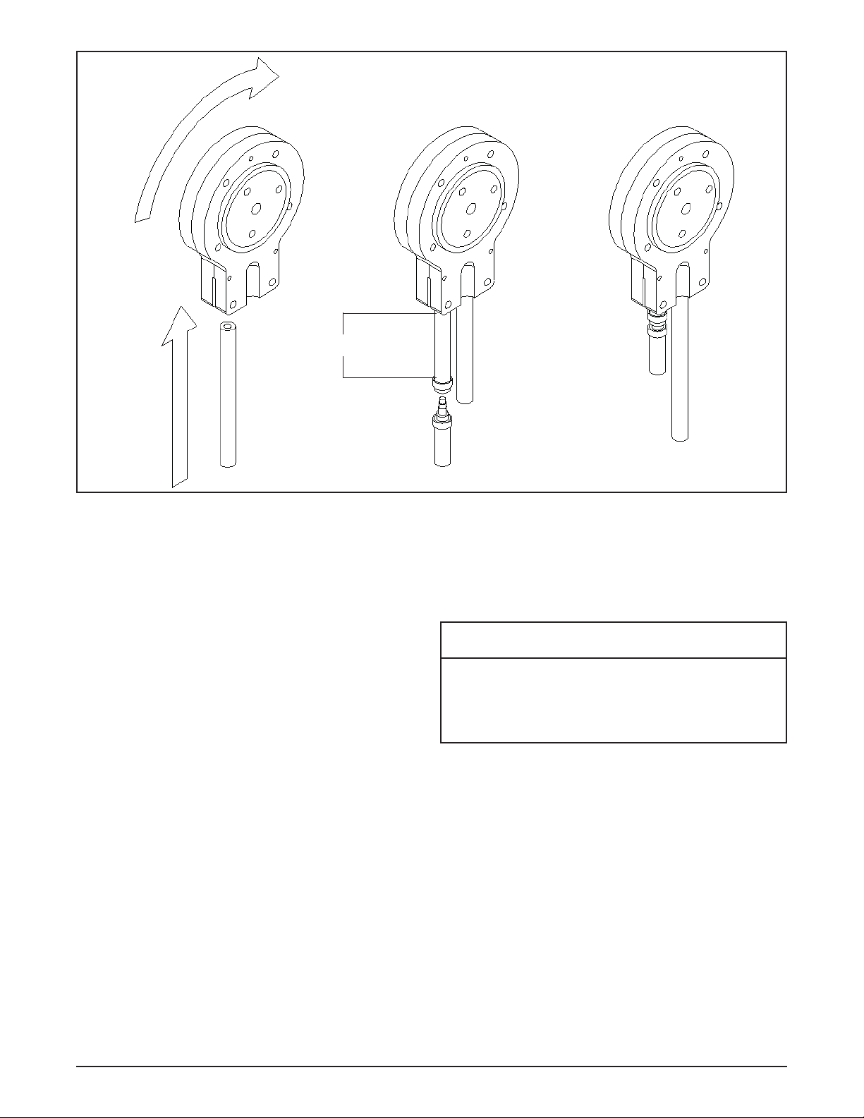
B. DISASSEMBLY OF AUGER
1. Remove the front auger support and bushing.
2. Remove the auger assembly from the machine.
Pull the auger out of the machine barrel slowly.
As the auger is being pulled out, carefully remove
each of the plastic fl ights with springs.
3. Keep the rear of the auger tipped up once it is
clear of the freezing cylinder to prevent the rear
seal assembly from dropping.
4. Wipe the hex drive anti-seize off of the hex end
of the auger with a paper towel. Remove the rear
seal assembly (Fig. 3-5).
5. Unscrew the springs from the auger fl ights.
Remove O-Ring
From Inside Insert
Figure 3-5 Rear Seal Assembly
Owner’s Manual #513635 Rev.5 9 O431B Model Machines
Page 16
3.4 CLEANING DISASSEMBLED PARTS
Disassembled machine parts require complete cleaning,
sanitizing and air drying before assembling. Local and state
health codes will dictate the procedure required. Some
state health codes require a four sink process (pre-wash,
wash, rinse, sanitize, air dry), while others require a three
sink process (without the pre-wash step). The following
procedures are a general guideline only. Consult your
local and state health codes for the procedures required
in your location.
A. Disassemble all parts. (Refer to Section 3.4 for
the disassembly of machine parts.)
B. Place all front door and auger parts in clean 90° to
1 10°F (32°C to 43°C) water and wash thoroughly
(four sink procedure only).
C. Place all parts in 90° to 110°F (32°C to 43°C) mild
detergent water and wash thoroughly.
D. Rinse all parts with clean 90° to 110°F (32°C to
43°C) water.
E. Sanitize all machine parts following procedures
outlined below.
3.5 SANITIZING MACHINE PARTS
A. Use a sanitizer, mixed according to manufacturer’s
instructions, to provide a 100 parts per million
strength solution. Mix sanitizer in quantities of
no less than 2 gallons of 90° to 110°F (32°C to
43°C) water. Any sanitizer must be used only in
accordance with the manufacturer’s instructions.
B. Place all parts in the sanitizing solution for 5
minutes, then remove and let air dry completely
before assembling in machine.
3.7 ASSEMBLING MACHINE
T o assemble the machine parts, refer to the following steps:
NOTICE
Petrol-Gel sanitary lubricant or equivalent must be
used when lubrication of machine parts is specifi ed.
NOTICE
The United States Department of Agriculture and
the Food and Drug Administration require that lubricants used on food processing equipment be certifi ed for this use. Use lubricants only in accordance
with the manufacturer’s instructions.
A. Assemble all o-rings onto parts dry, without
lubrication. Then apply a thin fi lm of sanitary
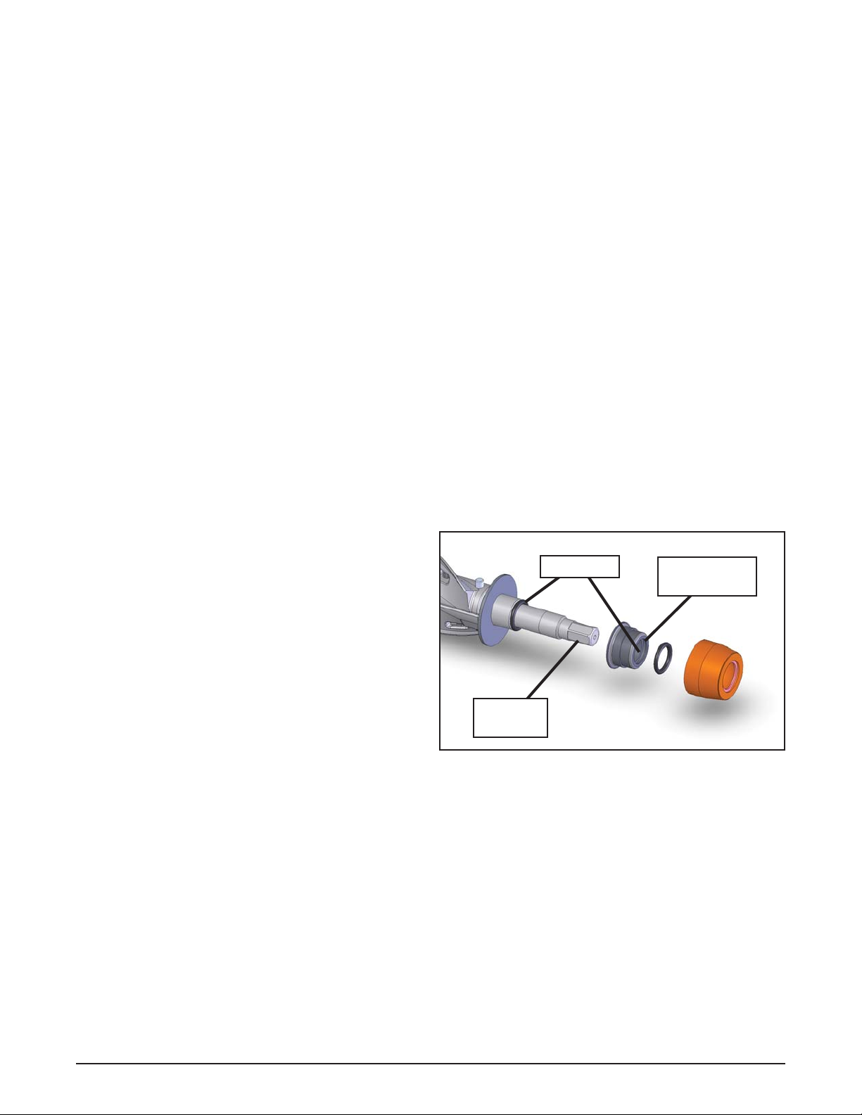
lubricant to exposed surfaces of the o-rings.
B. Lubricate the rear seal area on the auger shaft
with a thin layer of sanitary lubricant. Install the
rear seal o-ring. Lubricate the outside of the rear
seal o-ring with sanitary lubricant.
C. Install the stainless steel rear seal adapter into
the rear seal dry (without lubricant). Lubricate the
inside surface of the rear seal adapter, including
the adapter o-ring, and install it onto the auger
shaft. DO NOT lubricate the outside of the rear
seal adapter (Fig. 3-6).
Petrol-Gel
Place O-Ring
Inside Insert
3.6 CLEANING THE MACHINE
The exterior should be kept clean at all times to preserve
the luster of the stainless steel. A high grade of stainless
steel has been used on the machine to ease cleanup. To
remove spilled or dried mix, wash the exterior with 90° to
110°F (32°C to 43°C) soapy water and wipe dry.
Do not use highly abrasive materials, as they will mar the
fi nish. A mild alkaline cleaner is recommended. Use a soft
cloth or sponge to apply the cleaner. For best results, wipe
with the grain of the steel.
A. Clean the rear seal surface from inside of the
freezing cylinder.
B. Using sanitizing solution and the large barrel
brush provided, sanitize the freezing cylinder by
dipping the brush in the sanitizing solution and
brushing the inside of the freezing cylinder.
C. Remove the drip tray by pulling from the front
panel. Clean and replace the drip tray.
Owner’s Manual #513635 Rev.5 10 O431B Model Machines
D. Lubricate the hex drive end of the auger with
E. Screw the springs onto the studs in the plastic
F. Install the two plastic fl ights onto the rear of the
G. Install the remaining plastic fl ights, push the auger
Spline
Lubricant
Figure 3-6 Rear Seal Assembly
a small amount of hex drive anti seize. A small
container of anti seize is shipped with the machine.
fl ights. The springs must be screwed into the
fl ights completely to provide proper compression.
auger and insert it part way into the freezing
cylinder.
into the freezing cylinder and rotate slowly until
the auger engages the drive shaft.
Page 17
When sanitizing the machine, refer to local sanitary regulations for applicable codes and recommended sanitizing
products and procedures. The frequency of sanitizing
must comply with local health regulations. Mix sanitizer
according to manufacturer’s instructions to provide a 100
parts per million strength solution. Mix sanitizer in quantities of no less than 2 gallons of 90°F to 110°F (32°C to
43°C) water. Allow sanitizer to contact the surfaces to be
sanitized for 5 minutes. Any sanitizer must be used only
in accordance with the manufacturer’s instructions.
CAUTION
Figure 3-7 Front Door
H. Apply a thin layer of sanitary lubricant to the inside
and outside of the auger support bushing. Install
the bushing onto the auger support and install the
auger support into the front of the auger. Rotate
the auger support so that one leg of the support
points straight up.
H. Assemble the air bleed valve o-ring onto the air
bleed valve. Position the o-ring into the groove
close to the wide part. Apply a thin fi lm of sanitary
lubricant to the o-ring.
I. Insert the air bleed valve into the back of the front
door. Install the compression spring onto the air
bleed valve then screw the knob on fi nger tight.
J. Apply a thin layer of sanitary lubricant to the
o-rings on the spigot body and install the spigot
body through the bottom of the front door.
K. Apply a thin fi lm of sanitary lubricant to the door
seal o-ring and fi t it into the groove on the rear
of the front door.
M. Place the front door assembly on the mounting
studs and the push front door against the machine
carefully.
N. Secure the front door to the machine by placing
the knobs on the studs and tightening until fi nger
tight. Do not overtighten. Proper o-ring seal can
be observed through the transparent front door.
3.8 SANITIZING
Sanitizing must be done after the machine is clean and
just before the machine is fi lled with mix. Sanitizing the
night before is not effective. However , you should always
clean the machine and parts after using it.
NOTE
The United States Department of Agriculture and
the Food and Drug Administration require that all
cleaning and sanitizing solutions used with food
processing equipment be certifi ed for this use.
Risk of Product Damage
Avoid prolonged contact of sanitizer with machine
parts. Sanitizer may cause corrosion of stainless
steel parts if there is prolonged contact.
A. Prepare 2 gallons of sanitizing solution following
the manufacturer’s instructions. Pour it into a
clean container and place the container into the
cabinet. Put the mix pick-up tube in the sanitizer.
B. Place the mix pump switch in the ON position
and open the air bleed valve on the front door
by pushing the valve in and holding (see Figure
3-8).
Air Bleed
Valve
Figure 3-8 Air Bleed Valve
C. Let sanitizing solution fi ll the freezing cylinder to
the air bleed valve. Close the valve by pulling it
out to lock it into place.
D. Place the Main Power OFF/ON and Freezing
Cylinder OFF/ON switches in the ON position.
Press the CLEAN button.
E. Check for leaks when the freezing cylinder is fi rst
pressurized with sanitizing solution.
1. Check for leaks at the front door seals.
2. Check the drain tray located in the front panel
for leaks coming from the rear of the rear auger
seal.
3. Check the inside of the cab unit for leaks at
the hose connections.
Owner’s Manual #513635 Rev.5 11 O431B Model Machines
Page 18

F . Using a sanitized soft bristle brush (or equivalent)
dipped in sanitizing solution, clean the mix
container.
G. After fi ve minutes, open the spigot to expel
sanitizing solution. Drain all of the solution from
the machine.
H. When the solution has drained, press the CLEAN
button to stop the auger and place the Main Power
OFF/ON and Freezing Cylinder OFF/ON switches
in the OFF position. Allow the freezing cylinder
to drain completely.
The machine is now sanitized and ready for adding mix.
3.9 INITIAL FREEZE DOWN AND OPERATION
Every Stoelting soft serve machine needs to be set on site.
The following adjustment will provide optimal product
consistency while prolonging product life.
NOTE
The machine is designed for correct operation in
ambient temperatures between 50°F and 110°F.
T emperatures out of that range may cause refrigeration problems and product quality issues.
A. ADDING MIX
1. Sanitize the machine immediately before use.
2. Make sure the Freezing Cylinder OFF/ON switch
is in the OFF position.
3. Fill the mix container in the cab with at least 2.5
gallons of mix.
4. Attach the mix inlet probe to the container and
place the container in the refrigerated cab.
5. The mix pump switch is located inside the cab
unit. Place it in the ON position.
6. Place a container under the spigot and open the
spigot to allow the mix to fl ush out about 8 ounces
(0.23 liters) of sanitizing solution and liquid mix.
Close the spigot.
7. Open the air bleed valve on the front door by
pressing and holding. Hold the valve open until
the mix level in the freezing cylinder is 1/2” from
the air bleed valve.
B. PREPARING THE INTELLITEC CONTROL
8. On the IntelliT ec control, press and hold the SEL
button for 8 seconds. While still holding the SEL
button, press the up arrow () button. The LCD
will read “DISPLAY”.
9. Press the left arrow () button once. The display
will read “BASIC”.
10. Press the up arrow () button once. The display
will read “CutOut amps”.
1 1. Press the SET button. A cursor will start blinking
under the far right digit.
12. Change the value to 8.0. Press the left arrow ()
button to move the cursor. Press the up arrow ()
button to increase the digit. When a digit reaches
9, pressing the up arrow () button again will
change the value to 0.
13. After entering 8.0, press SET to save this value.
The LCD will read “CutOut Set -- OK”.
14. Press the SEL button. The LCD will read “CutOut
amps 8.0”.
15. Press the SEL button twice. The LCD will read
“DISPLAY”.
16. Press the up arrow () button to navigate to the
“°F” and “amps” readings.
C. INITIAL FREEZE DOWN
17. Place the Freezing Cylinder OFF/ON switch in
the ON position.
18. Press the PUSH TO FREEZE button.
NOTE
After the drive motor starts, there is a 3-second
delay before the compressor starts.
19. As the product freezes, the “amps” value on the
display will increase. When it reaches 2.8A, open
the spigot, take a 6-8 ounce sample and measure
the temperature. For most soft serve mixes,
the desired temperature is between 19.0°F and
19.5°F.
20. Draw samples at every increase of 0.2A until
reaching the desired consistency and temperature.
NOTE
Show the sample to the customer and make sure it
meets their required consistency and temperature.
21. Record the “amps” value.
22. Place the Freezing Cylinder OFF/ON switch in
the OFF position.
D. ADJUSTING THE INTELLITEC CONTROL
23. Press the SEL button. The display will read
“DISPLAY”.
24. Press the left arrow () button once. The display
will read “BASIC”.
25. Press the up arrow () button once. The display
will read “CutOut amps”.
26. Change the value to the recorded value by
pressing the SET button. A cursor will start blinking
under the far right digit.
27. Press the left arrow () button to move the cursor.
Press the up arrow () button to increase the digit.
When a digit reaches 9, pressing the up arrow
() button again will change the value to 0.
Owner’s Manual #513635 Rev.5 12 O431B Model Machines
Page 19

28. Press the SET button to save the value. The LCD
will read “CutOut Set -- OK”.
29. Press the SEL button. The LCD will read “CutOut
amps” along with the programmed value from the
previous step.
30. Press the SEL button three times. The LCD will
read “EXITMENU”.
31. Press the up arrow () button to exit the menu.
32. Adjustment to the control is completed.
E. SERVING PRODUCT
33. Place the Freezing Cylinder OFF/ON switch in
the ON position.
34. Press the PUSH TO FREEZE button.
35. When the product is at 75% consistency, the
display will read “SERVE”.
36. For normal dispensing, move the spigot handle
fully open.
37. The machine dispenses product at a reasonable
draw rate. If the machine is overdrawn, the result
is a soft product or a product that will not dispense
at all. If this occurs, allow the machine to run for
approximately 30 seconds before dispensing more
product. A dispense rate adjustor is located under
the header panel, to the immediate right of the
spigot handle. Turning the knob counterclockwise
will decrease the dispense rate.
38. Do not operate the machine when the MIX LOW
message is displayed. Refi ll the mix container
immediately.
NOTE
The machine has a standby and sleep mode. After
a preset number of freezing cycles, it will enter the
standby mode (followed by sleep mode) and remain
there until someone draws product or presses the
PUSH TO FREEZE button. In the sleep mode, the
machine will keep the product below 41°F (5°C).
Sleep modes do not take the place of cleaning
and sanitizing. Federal, State, and local regulatory
agencies determine frequency of cleaning and
sanitizing.
E. Place the mix pump switch in the ON position.
F. Place a container under the spigot and open the
spigot to allow the mix to fl ush out about 8 ounces
(0.23 liters) of sanitizing solution and liquid mix.
G. Open the air bleed valve on the front door by
pressing and holding. Hold the valve open until
the mix level in the freezing cylinder is 1/2” from
the air bleed valve.
H. Place the Freezing Cylinder OFF/ON switch in
the ON position.
I. Press the PUSH TO FREEZE button.
NOTE
After the drive motor starts, there is a 3-second
delay before the compressor starts.
J. When the product is at 75% consistency, the
display will read “SERVE”. Open the spigot to
dispense product.
K. The machine dispenses product at a reasonable
draw rate. If the machine is overdrawn, the result
is a soft product or a product that will not dispense
at all. If this occurs, allow the machine to run for
approximately 30 seconds before dispensing more
product. A dispense rate adjustor is located under
the header panel, to the immediate right of the
spigot handle. Turning the knob counterclockwise
will decrease the dispense rate.
M. Do not operate the machine when the MIX LOW
message is displayed. Refi ll the mix container
immediately.
NOTE
The machine has a standby and sleep mode. After
a preset number of freezing cycles, it will enter the
standby mode (followed by sleep mode) and remain
there until someone draws product or presses the
PUSH TO FREEZE button. In the sleep mode, the
machine will keep the product below 41°F (5°C).
Sleep modes do not take the place of cleaning
and sanitizing. Federal, State, and local regulatory
agencies determine frequency of cleaning and
sanitizing.
3.10 NORMAL FREEZE DOWN AND
OPERATION
The following section contains the recommended operating procedures for the safe operation of the machine.
A. Sanitize immediately before use.
B. Make sure the Freezing Cylinder Off/On switch
is in the OFF position.
C. Fill the storage container in the cab with at least
2.5 gallons of mix.
D. Attach the mix inlet probe to the container and
place the container in the refrigerated cab.
Owner’s Manual #513635 Rev.5 13 O431B Model Machines
3.11 MIX INFORMATION
Mix can vary considerably from one manufacturer to
another. Differences in the amount of butterfat content
and quantity and quality of other ingredients have a
direct bearing on the fi nished frozen product. A change
in machine performance that cannot be explained by a
technical problem may be related to the mix.
Proper product serving temperature varies from one
manufacturer’s mix to another. Mixes should provide a
satisfactory product in the 20°F to 24°F range. Diet and
low-carb mixes typically freeze to proper consistency at
higher temperatures.
Page 20

When checking the temperature, stir the thermometer in
the frozen product to get an accurate reading.
Old mix, or mix that has been stored at too high a temperature, can result in a fi nished product that is unsatisfactory.
To retard bacteria growth in dairy based mixes, the best
storage temperature range is between 33° to 38°F (0.5°
to 3.3° C).
3.12 OPERATION OF MIX PUMP
The mix pump switches are located inside the refrigerated
cabinet. When a pump switch is placed in the ON position, the mix pump motor will start pumping mix into the
freezing cylinder. When the set pressure is reached, the
mix pump will shut off automatically. When the switch is
placed in the OFF position, the mix pump will not operate.
NOTE
The mix pump motor is equipped with an internal
overload that will “trip”, disabling the pump when
the motor is overloaded. Consult the trouble shooting section for corrective information. The internal
overload will automatically reset after cooling. If
the condition continues, contact a qualifi ed service
person.
A. Mix Operation: The peristaltic mix pump contains
one continuous mix pump hose. When looking at
the face of the peristaltic mix pump, the left side
of the hose is the mix intake or pickup. The right
side of the hose is the mix discharge. Mix is drawn
up the pickup side of the hose and transferred
through the discharge side to the machine (Fig.
3-9).
Air/mix to
Air Line
Freezing
Cylinder
3-way
Tee
B. Air Operation: The air compressor operates
whenever the peristaltic mix pump is running.
Air enters through a check valve on the piston
downstroke. The air is discharged through a
second check valve, on the piston upstroke. The
air and mix join at the tee and then travel to the
machine.
C. The overrun adjustment is preset at the factory.
If an adjustment becomes necessary, refer to
Section 4.
3.13 MIX PUMP CLEANING
NOTICE
Any cleaning procedure must always be followed
by sanitizing before fi lling machine with mix. (Refer
to section 3.3)
The mix pump is approved for CIP (clean in place). It is
thoroughly cleaned when the detergent solution is pumped
through the machine. We recommend completely disassembling the pump and disconnecting tubing every 14
days for inspection of parts to confi rm the CIP has been
properly performed. If any residue is detected, clean or
replace those parts as outlined below.
A. Place the Main Power OFF/ON and Freezing
Cylinder OFF/ON switches in the ON position
and press the CLEAN button. Allow the auger to
agitate for 5 to 10 minutes.
B. Remove the suction tube from the mix container.
Open the spigot to remove the mix remaining in
the freezing cylinder.
C. Pump 2 gallons (7.5 liters) of potable water through
machine until the water coming out of the spigot
is clear.
D. Pump 2 gallons (7.5 liters) of 90° to 1 10°F (32°C
to 43°C) detergent solution through the machine.
The use of soft water is recommended, along with
dishwashing detergents such as “Joy”, “Dawn”,
or equivalent.
E. Place the mix pump switch in the OFF position.
Open the spigot to relieve the remaining pressure.
F. Press the CLEAN button to stop the auger and
place the Main Power OFF/ON and Freezing
Cylinder OFF/ON switches in the OFF position.
Mix
Intake
Figure 3-9 Mix Pump Hose Routing
Owner’s Manual #513635 Rev.5 14 O431B Model Machines
Mix
Discharge
Page 21
3.14 DISASSEMBLY AND INSPECTION OF
REMOVABLE PARTS
Inspection of removable parts should be made whenever
maintenance is performed or when the pump requires
disassembly.
NOTE
If the mix line or air line is diffi cult to remove, soften
the tubing with a rag soaked in hot water. Hose
connections may be sprayed with Haynes Sanitary
Lubricant for ease of removal.
WARNING
Hazardous Moving Parts
Revolving pump head can grab, mangle, and
cause serious crushing injury . The Main Power Off/
On switch must be placed in the OFF position for
cleaning and power must be disconnected when
disassembling or servicing.
CAUTION
System Under Pressure
Never disconnect hoses from the machine or the
pump without fi rst opening the spigot to relieve
pressure.
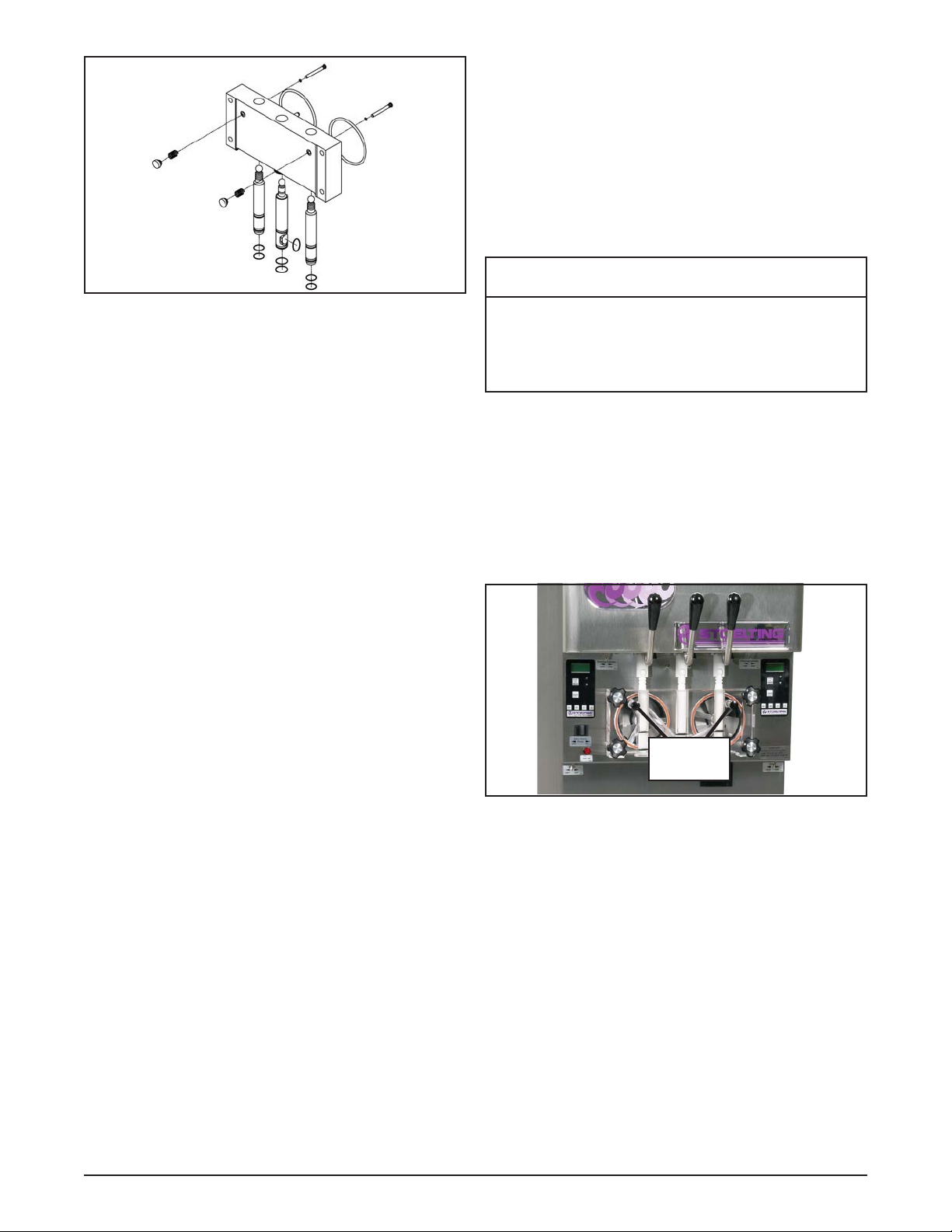
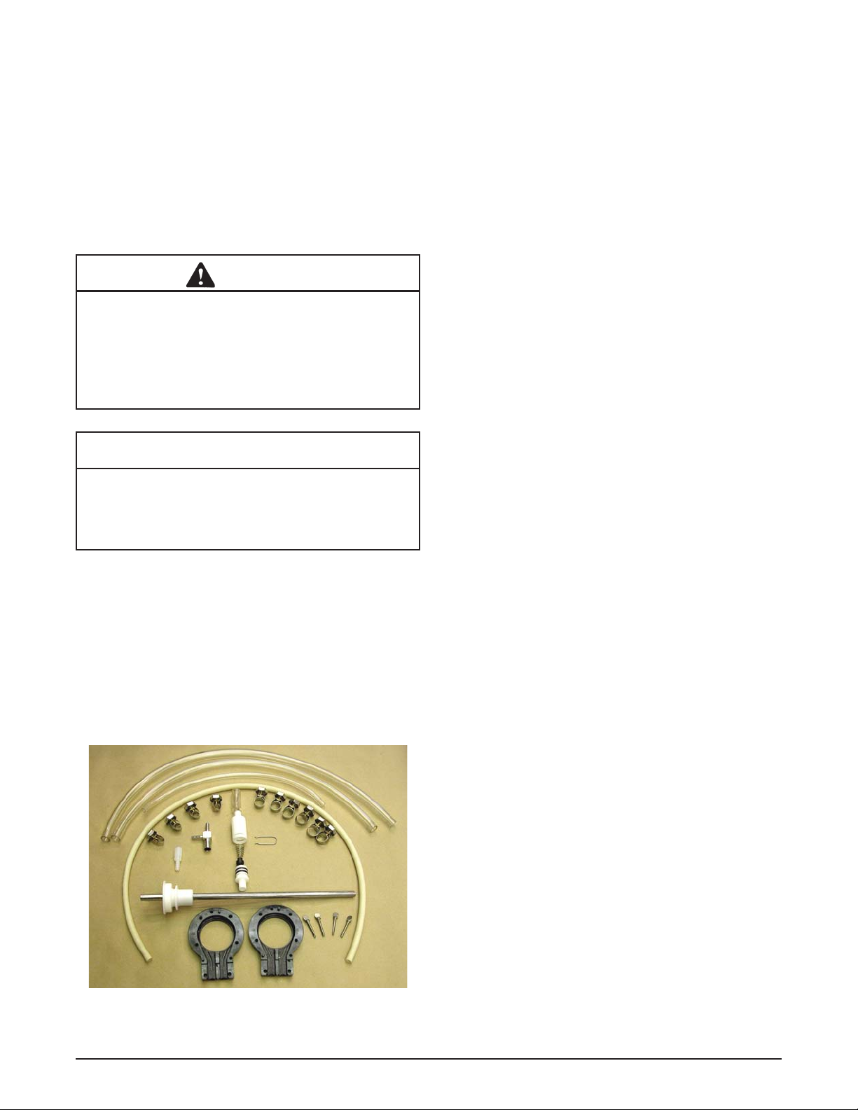
C. Completely disassemble the hose assembly and
the check valve (Fig. 3-10). Place hoses, tee,
check valve assembly, and pickup hose adapter in
90° to 1 10°F (32°C to 43°C) mild detergent water
and wash thoroughly . Use soft bristle brushes to
clean inside of fi ttings. Rinse all parts in clean
90° to 110°F (32°C to 43°C) water.
D. Carefully inspect each part for wear or damage.
Replace worn or damaged parts.
E. Wash the feed tube and the air tube in the cabinet
with 90° to 110°F detergent water and brushes
provided. Rinse with clean, 90° to 110°F water.
F. Prepare two gallons (7.5 liters) of sanitizing
solution using a USDA certifi ed grade sanitizing
solution. Sanitize all removed parts. Allow them
to air dry.
G. Check the Hose Service Record decal to determine
if a hose reposition or a hose replacement is
required.
H. Reassemble both hose assemblies per the
diagram located on the inside of the cab door.
Reconnect the assemblies to the pump hose and
the discharge hose, using the clamps. (Refer to
Section 2.5 Mix Pump).
I. Sanitize assembled machine as per instructions
outlined in Section 3.9.
A. Loosen the clamp and remove the air hose from
the pump compressor.
B. Loosen the clamp and disconnect the mix pump
hose. Remove the pickup hose, the mix check
valve and the pickup hose adapter (and bag
adapter if applicable) as an assembly from the
mix container.
Figure 3-10 Mix Pump Removable Parts
Owner’s Manual #513635 Rev.5 15 O431B Model Machines
Page 22

Owner’s Manual #513635 Rev.5 16 O431B Model Machines
Page 23

SECTION 4
MAINTENANCE AND ADJUSTMENTS
4.1 MACHINE ADJUSTMENT
This section is intended to provide maintenance personnel
with a general understanding of the machine adjustments.
It is recommended that any adjustments in this section
be made by a qualifi ed person.
4.2 PRODUCT CONSISTENCY
ADJUSTMENT
The operator can adjust product consistency by modifying
the Fine Adjustment setting on the membrane switch. This
is the only adjustment that can be made by the operator
without using a pass code key sequence. Increasing this
setting will increase the drive motor amperage cutout and
increase product consistency. Follow the instructions
below to make fi ne adjustments to product consistency.
A. Place the Main Freezer Power switch in the ON
position.
B. Press the SET button on the Control Panel once.
Fine Adj will appear on the LCD screen.
C. Press the up arrow button until the desired
consistency setting is displayed. The higher the
number, the fi rmer the product consistency. The
control may be set from 1 to 9. The value increases
by 1 each time the up arrow button is pressed.
After the value reaches 9, numbering restarts at
0. The 0 setting cannot be set.
D. Press the SET button once to save the setting
and return to the current mode display.
4.3 LOCKING THE CONTROL PANEL
The IntelliT ec control has a tamper proof mode to prevent
unauthorized use. When set, all buttons on the control
panel are disabled. Follow the instructions below to lock
the control panel
A. Press and hold the PUSH TO FREEZE button
for at least 5 seconds.
B. While still holding the PUSH TO FREEZE button,
press the CLEAN button once.
C. Release both buttons. An asterisk (*) will appear
on the bottom line of the display, indicating that
the control is in the lock out mode.
NOTE:
Repeat steps A, B, and C to unlock the control
panel.
4.4 OBTAINING READINGS AND
MODIFYING SETTINGS (SERVICE PERSONNEL
ONLY)
Readings and settings on the IntelliTec control are accessed through the IntelliTec control menu settings.
Locating machine readings and system function settings
are done using the up arrow () and left arrow () buttons on the membrane switch. A printed IntelliTec Menu
Settings sheet is located in the information pouch behind
the header panel.
IntelliTec Control Readings
To obtain machine readings, locate the value on the machine’s menu settings sheet and follow the steps below.
A. Press and hold the SEL button for 8 seconds. While
still holding the SEL button, press the up arrow
button (). The LCD screen will read DISPLAY.
B. Release both buttons.
C. Press the up arrow button () to navigate to the
correct reading under DISPLA Y or press the left
arrow () button to navigate to the ERRCODES
menu.
D. Press the up arrow () and left arrow () buttons
to navigate through the rest of the readings as
needed.
E. When all readings have been obtained, press
the up arrow button () from ExitMenu to return
to the current mode display.
Modifying Control Settings
To change the value of a system function, locate the
function on the IntelliTec Settings Menu and follow the
steps below.
Figure 4-1 Touchpad
Owner’s Manual #513635 Rev.5 17 O431B Model Machines
Page 24

IMPORTANT:
Before making changes to any settings, record
the original values. If the setting changes do not
achieve desired results, return settings to their
original values.
A. Press and hold the SEL button for 8 seconds. While
still holding the SEL button, press the up arrow
button (). The LCD Screen will read DISPLAY.
B. Release both buttons.
C. Press the left arrow button () to get to the correct
menu (Basic, Advanced, or Storage).
D. Press the up arrow button () to navigate to the
value that needs to be changed.
E. Press the SET button to enter the edit mode.
F. Press the up arrow button () to change the
setting.
G. Press the SET button to save the setting and exit
the edit mode.
H. Press the up arrow () and the left arrow ()
buttons to navigate through the rest of the settings
as needed.
I. When all changes have been completed, press
the up arrow button () from ExitMenu to return
to the current mode display.
4.5 READINGS (SERVICE PERSONNEL
ONLY)
The IntelliTec control continuously monitors and records
temperatures, voltages, amps, and error code details.
Each reading is benefi cial to service personnel when
troubleshooting.
DISPLAY READINGS
Following are the readings available under the DISPLA Y
menu:
Cabinet
The temperature of the cab is constantly monitored
by the IntelliTec control.
Cycles (count)
This reading counts down the number of cycles
in the current “Serve Mode”. The starting value
is dependant upon the Cycles setting on the
IntelliTec control.
°F and amps
Suction line temperature on the freezing cylinder
and drive motor amps are available on the same
screen to assist with setup and troubleshooting.
Aux. Temp (°F)
This reading provides the ambient temperature
around the IntelliTec control board.
Supply V (VAC)
A calculated input voltage is recorded.
ERROR CODE READINGS
The following details are recorded under the ERRCODES
menu for each of the last 25 error codes received:
Err1 (hours)
A timer begins when an error occurs. The timer
records the number of hours since the error
occurred. If power to the machine is interrupted,
the timer will stop until power has been restored.
°F and amps
The suction gas temperature on the freezing
cylinder and the drive motor amps are recorded
at the time of the error.
Aux. Temp (°F)
Ambient temperature of the IntelliTec control board
is recorded at the time of the error.
Str (°F)
The storage temperature is recorded at the time
of the error.
VAC and Mode
A calculated input voltage and mode at which
the error occurred are recorded. Following are
descriptions of each mode:
Mode Description
0 Start of freezing cycle
1 Compressor and drive motor on
2 Stir Cycle
3 Compressor off
4 “Standby Mode”
5 “Sleep 1 Mode”
6 “Sleep 2 Mode”
7 “Clean Mode”
8 Startup
9 Storage only refrigeration
10 Freezing cycle is shut down
11 Door safety switch triggered
12 High pressure cutout
Up Time (hours)
This value is a record of the total time the machine
has been in service. If power is interrupted, the
timer will stop until power is restored. This timer
does not reset.
Owner’s Manual #513635 Rev.5 18 O431B Model Machines
Page 25

RUN STATISTICS
In addition to dynamic readings and recorded error code
details, the IntelliTec control records rolling averages of
run statistics. Following are the readings available under
the RUNSTATS menu:
On Times (sec)
The control records the time of each freezing
cycle and provides a rolling average.
Off Times (sec)
The control records the time between freezing
cycles and provides a rolling average.
Brl. Min (°F)
The lowest average barrel temperature is
recorded.
Brl. Max (°F)
The highest average barrel temperature is
recorded.
Stor Min (°F)
The lowest average cabinet temperature is
recorded.
Stor Max (°F)
The highest average cabinet temperature is
recorded.
Power On (hrs)
This value is a record of the time the machine
has been in service. If power is interrupted, the
timer will reset.
4.6 ADJUSTMENTS (SERVICE PERSONNEL
ONLY)
The following adjustments directly affect product consistency and length of time in “Serve Mode”. The default
settings have been created using a 5% milkfat soft serve
mix and provide optimal product consistency while prolonging product life.
CutOut (amps)
It is recommended to set the CutOut value at
initial startup and when changing mix types.
Adjustments to this setting directly affect the length
of the freezing cycle and indirectly change product
consistency. To properly set the CutOut value,
during startup navigate to the “°F” and “amps”
values under the Display menu (Refer to Section
4.4), start the machine and freeze the product to
the desired consistency . Monitor consistency by
taking a 6 ounce sample at each change of the
“amps” display. When the desired consistency has
been reached, record the temperature and amps,
and change the CutOut value to the recorded
amps value
Cut In T (°F)
After the consistency value has been determined,
the Cut In T value can be adjusted. The Cut In
T is the temperature of the refrigerant gas in the
evaporator at the front of the freezing cylinder.
Changing this setting changes the temperature at
which the freezing cycle starts. This value along
with the CutOut value determines the range of
temperatures (or “temperature window”) of the
product. Decreasing the temperature decreases
the temperature window and, under normal use,
increases the amount of freezing cycles. This
creates a greater chance of product breakdown
by stirring the product often. Increasing the Cut
In T increases the temperature window, which
decreases freezing cycles and increases the
chance of heat shock within the product.
Cycles (count)
This setting determines the number of freezing
cycles during “Serve Mode”. Increasing the value
will increase the total time in “Serve Mode”. Factory
default is 20 cycles, which results in “Serve Mode”
lasting about 2-1/2 hours without the PUSH TO
FREEZE button being pressed or a spigot handle
being pulled. If the PUSH TO FREEZE button is
pressed or the spigot handle is pulled at any time
during “Serve Mode”, the Cycles count will reset.
4.7 OTHER SETTINGS (SERVICE PERSONNEL
ONLY)
Changing any setting on the IntelliTec control will alter
machine operation and affect the product temperature,
consistency , or life. Refer to the IntelliT ec Control System
Settings sheet located in the information pouch behind
the header panel of the machine. If any of the following
settings on the IntelliTec control differ from the System
Settings sheet, it is recommended to return those settings
to factory defaults.
Stir On (sec)
Adjustments to this setting affect the amount of
time the auger rotates in the stir cycle. The stir
cycle occurs in “Serve Mode”, “Standby Mode”,
and “Sleep 2 Mode”.
Stir Off (sec)
Adjustments to this setting affect the time between
stir cycles. The stir cycle occurs in “Serve Mode”,
“Standby Mode”, and “Sleep 2 Mode”.
On Time (sec)
Increasing this value will increase the length of the
freezing cycle during “Standby Mode” and result
in a decrease of average product temperature in
the barrel.
Owner’s Manual #513635 Rev.5 19 O431B Model Machines
Page 26

Off Time (sec)
Increasing this value will increase the time between
freezing cycles in “Standby Mode” and result in
an increase of product temperature in the barrel.
Stb Time (sec)
This setting determines the total amount of time
in “Standby Mode”.
Sl1DrvOn (sec)
Adjustments to this setting affect the amount of
time the auger rotates in the stir cycle. This stir
cycle only occurs in “Sleep 1 Mode”.
Sl1DrOff (sec)
Adjustments to this setting affect the time between
stir cycles. The stir cycle only occurs in “Sleep 1
Mode”.
Sl2CutIn (°F)
Changing this setting affects the temperature at
which the freezing cycle starts in “Sleep 2 Mode”.
Sl2CtOut (°F)
Changing this setting affects the temperature at
which the freezing cycle stops in “Sleep 2 Mode”.
DftOffTm (sec)
In “Serve Mode”, this value determines the
maximum time without a freezing cycle. If this
value is met, a freezing cycle will start. In the event
of a freezing cylinder temperature sensor failure,
this value affects the amount of time between
freezing cycles during “Serve Mode”.
Refriger
This setting changes how the control handles
the storage refrigeration cycle. The setting for
the O411 is Cabinet.
CabCutIn (°F)
If the Refriger value is set to Cabinet, this
setting determines the temperature at which
the refrigeration cycle starts. If None, 1 Hopper,
or 2 Hopper is selected for the Refriger setting,
CabCutIn will not be shown on the IntelliT ec menu.
CabCtOut (°F)
If the Refriger value is set to Cabinet, this
setting determines the temperature at which
the refrigeration cycle stops. If None, 1 Hopper,
or 2 Hopper is selected for the Refriger setting,
CabCtOut will not be shown on the IntelliTec
menu.
Cab Off
If the Refriger value is set to Cabinet and the
temperature sensor in the cabinet fails, this setting
determines the time between refrigeration cycles.
If None, 1 Hopper, or 2 Hopper is selected for the
Refriger setting, Cab Off will not be shown on the
IntelliTec menu.
Cab On
If the Refriger value is set to Cabinet and the
temperature sensor in the cabinet fails, this setting
determines the length of the refrigeration cycle. If
None, 1 Hopper, or 2 Hopper is selected for the
Refriger setting, Cab On will not be shown on the
IntelliTec menu.
4.8 OVERRUN ADJUSTMENT
The product, when served, is a combination of air and
mix. Overrun is a measure of the amount of air blended
into the mix.
Overrun can be expressed in terms of the amount of
weight loss for a given volume. For example, if a pint of
liquid mix weighs 18 ounces and a pint of frozen product
with air added weighs 12 ounces, the overrun is said to
be 50 percent: 18 oz. - 12 oz. = 6 oz., (6/12) x 100 = 50%
The overrun can be checked by placing a one pint container on an ice cream scale and zeroing out the scale.
Then fi ll a one pint container with frozen product. The
container should be fi lled over the top and leveled with
a straightedge. The product should not contain any air
pockets. When weighed on an ice cream scale, one pint
of product should weigh 12 to 13 ounces.
The mix pump has been preset at the factory to produce
a product with approximately 40% overrun. Because of
differences in mix formulation, temperatures and barometric pressure, this fi gure may vary . It will be necessary
for approximately 2 gallons of mix to be pumped through
the machine before overrun changes in the product are
noticeable.
Overrun is controlled by the length of the air compressor
piston stroke within the piston cylinder. Lengthening the
stroke within the cylinder will increase overrun. Conversely,
shortening the stroke will decrease overrun. To perform
an overrun adjustment, refer to the following procedure:
WARNING
Hazardous Voltage
The Main Freezer Power switch must be placed in
the OFF position when disassembling for servicing.
The freezer must be disconnected from electrical
supply before removing any access panel. Failure
to disconnect power before servicing could result
in death or serious injury.
Owner’s Manual #513635 Rev.5 20 O431B Model Machines
Page 27

A. Turn the mix pump switch to the OFF position.
Disconnect power sources/circuit breakers.
B. Remove the back panel from the machine.
C. On the air compressor side of the pump, locate
the long/slender piston rocking arm. The rocking
arm downward travel is limited by a stationery
cam. On the face of the cam there is an overrun
setting indicator plate numbered 3 through 8 and
an adjustment knob (Fig. 4-2).
Pickup
End
Figure 4-3 Pump Hose Reposition
D. Loosen the small clamp at the pick-up hose
Figure 4-2 Overrun Adjustment
E. Cut 7-1/2 inches off the end of the mix pump
D. The overrun setting is indicated by a pin.
E. To adjust overrun, loosen the allen-head screw
(located within the center of the adjustment knob)
with the 5/32” allen wrench provided. Rotate the
adjustment knob counterclockwise to a higher
number for higher overrun, or clockwise to a lower
number for lower overrun. Each number multiplied
by 10 represents the overrun percentage (i.e.
setting 4 = 40% overrun).
F. Tighten the allen screw, then place the wrench
back in its clip. Replace the lower back panel and
secure with the four screws. Turn the mix pump
power switch to the ON position.
4.9 MIX PUMP HOSE REPOSITION
Mix pump hose must be repositioned every 800 gallons
of mix pumped or every 2 weeks. Failure to reposition
the hose will result in reduced mix pump liquid capacity,
dispense stoppage, popping, and possible mix pump hose
leakage. Follow the steps below to reposition the hose:
A. Run cleaning solution through pump.
B. Turn the pump off and relieve any pressure by
opening the spigot.
C. Grasp the pickup hose end of the mix pump hose
with one hand and turn the pump on. Pull down
on the pickup hose end until 12 to 14 inches of
tubing has fed through the pump then turn the
pump off (Fig. 4-3).
Owner’s Manual #513635 Rev.5 21 O431B Model Machines
F. Reconnect the mix pump hose to the adapter.
G. Continue normal operation. Mix hose will
4.10 MIX PUMP HOSE REPLACEMENT
Mix pump hose must be replaced when tubing cannot be
further repositioned (every four to eight weeks). Failure
to comply will result in hose failure and possible pump
damage. Follow the steps below to replace the hose:
A. Run cleaning solution through pump.
B. Turn the pump off and relieve any pressure by
C. Disconnect the mix pump hose at each end.
D. Grasp the discharge hose end with one hand and
E. Rotate pump roller assembly so one roller is at
F . Use a brush that fi ts in the opening and clean the
adapter and disconnect the mix pump hose.
hose.
automatically reposition itself with the adapter
near the black cover.
Each hose is long enough for 3 repositions before
replacement is required.
opening the spigot.
turn the pump on. Pull down on the hose until all
of the remaining hose is removed from the pump.
Turn pump off.
the 6:00 position.
pump roller assembly, fi rst with detergent water
and then clear water.
12” to 14”
NOTE
Page 28

G. Connect the new mix pump hose to the pickup
hose adapter using the small clamp.
H. Feed one end of the mix pump hose into the
pickup hose side (left) of the black cover.
NOTE
Feed the tube into the clamp so the natural curve of
the tube is towards the outside of the black cover.
This prevents the hose from looping around the
black cover twice.
C. Press the left arrow button () three (3) times to
navigate to the Storage menu.
D. Press the up arrow button () once to navigate
to the CabCutIn value. Record this value.
IMPORTANT:
Before making changes to any settings, record
the original values. If the setting changes do not
achieve desired results, return settings to their
original values.
I. Gently push the hose into the black cover until it
begins to feed.
J. Allow the hose to feed itself through the pump
until about 6” (15cm) remains on the entering
side.
K. Turn pump off.
L. Connect the mix pump hose to the elbow fi tting
(located on the left side of the mix line manifold)
using a small hose clamp. Be careful not to twist
the mix hose.
M. Turn the pump on.
N. Allow the remaining 6” (15cm) of tubing to feed
through the pump until the hose adapter prevents
further feeding.
O. Turn the pump off.
CAUTION
Risk of Product Damage
Air/Mix Tee must remain below the black cover
clamp. If the Tee is above the pump, the mix may
drain into the air compressor, resulting in pump
damage.
P . Connect the free end of the mix pump hose to the
3-way Tee. When all connections are complete,
the 3-way T ee must be lower than the black pump
housing.
Q. The pump is now ready to sanitize.
E. Press SET button to enter edit mode.
F. Press the up arrow button () to increase the
number to the value required. The value increases
by 1 each time the up arrow button () is pressed.
After the value reaches 9, numbering restarts at
0.
G. Press SET button to save the setting and exit the
edit mode.
H. Press the up arrow button () once to navigate
to the CabCtOut value. Record this value.
I. Press SET button to enter edit mode.
J. Press the up arrow button () to increase the
number to the value required. The value increases
by 1 each time the up arrow button () is pressed.
After the value reaches 9, numbering restarts at
0.
K. Press SET button to save the setting and exit the
edit mode.
L. Press the up arrow () and left arrow () buttons
to navigate to ExitMenu.
M. Press the up arrow button () from ExitMenu to
return to the Mode Screen.
N. Locate the Specifi cation Sheet for SU412 Control
behind the header panel and record the new
values on this sheet.
4.12 DRIVE BELT TENSION ADJUSTMENT
A. Remove a side panel and the back panel.
B. Press fi rmly on one belt.
4.11 CAB TEMPERATURE ADJUSTMENT
Cab temperature is monitored and controlled by two settings on the IntelliTec control: CabCutIn and CabCtOut.
The cut in value determines the temperature at which the
refrigeration cycle starts. The cut out setting determines
when the cycle stops. To change the CabCutIn or CabCtOut, follow the steps below:
A. Press and hold SEL button for 8 seconds. While
still holding the SEL button, press the up arrow
button (). The LCD Screen will read "Display".
B. Release both buttons.
Owner’s Manual #513635 Rev.5 22 O431B Model Machines
Hazardous Voltage
The Main Freezer Power switch must be placed in
the OFF position when disassembling for servicing.
The freezer must be disconnected from electrical
supply before removing any access panel. Failure
to disconnect power before servicing could result
in death or serious injury.
WARNING
Page 29

C. When the tension is properly adjusted, the belt
will depress the approximate width of the belt with
the pressure of a fi nger.
D. If an adjustment is necessary, loosen the four
motor plate retaining nuts, adjust belt tension
then retighten the four nuts.
NOTE
Belt life will be increased if new drive belts are
tightened after two or three weeks of operation.
4.13 CONDENSER CLEANING (AIR-COOLED
MACHINES)
The condenser requires periodic cleaning. To clean the
condenser, refer to the following steps:
A. Lift the condenser fi lter off of the machine cover
panel. Visually inspect the condenser fi lter for dirt
(Fig. 4-4).
The United States Department of Agriculture and the Food
and Drug Administration require that lubricants used in
food zones be certifi ed for this use. Use lubricants only in
accordance with the manufacturer’s instructions.
A. Daily checks
Check for any unusual noise or condition and
repair immediately.
B. Monthly checks
1. Check drive belts for wear and tighten belts if
necessary. (Refer to section 4.12)
2. Check the condenser fi lter for dirt. (Refer to
section 4.13).
4.15 EXTENDED STORAGE
Refer to the following steps for winterizing the machine
or for storing the machine over any long period.
A. Clean all of the parts that come in contact with
mix thoroughly with warm detergent . Rinse in
clear water and dry all parts. Do not sanitize.
NOTE
Do not let cleaning solution stand in freezing cylinder or mix pump during the shutdown period.
Figure 4-4 Removing Condenser Filter
B. If the condenser fi lter is dirty, vacuum or brush
it clean. Rinse it with clean water and allow it to
dry before replacing it on the machine.
NOTE
If the condenser is not kept clean, refrigeration effi ciency will be lost.
4.14 PREVENTATIVE MAINTENANCE
It is recommended that a preventative maintenance
schedule be followed to keep the machine clean and
operating properly . The following steps are suggested as
a preventative maintenance guide.
B. Remove, disassemble, and clean the front door,
auger shaft, and mix pump. Leave disassembled
during the shutdown period.
C. Place the plastic auger fl ights in a plastic bag with
a moist paper towel. This will prevent the fl ights
from becoming brittle if exposed to dry air over
an extended period (over 30 days).
D. For water-cooled machines that are left in unheated
buildings, or buildings subject to freezing, the water
must be shut off and disconnected. Disconnect
the fi ttings at the water inlet and the water outlet
lines of the machine. The fi ttings are located at
the rear of the machine. Run the compressor for
2 - 3 minutes to open the water valve. Blow out
all the water, fi rst through the water inlet, then
through the water outlet lines with air or carbon
dioxide. Drain the water supply line coming to the
machine.
E. Place the Pump OFF/ON switch and the Main
Freezer Power OFF/ON switch in the OFF
position.
F. Disconnect the machine from the source of the
electrical supply in the building.
Owner’s Manual #513635 Rev.5 23 O431B Model Machines
Page 30

Owner’s Manual #513635 Rev.5 24 O431B Model Machines
Page 31

SECTION 5
TROUBLESHOOTING
5.1 ERROR CODES
When the machine experiences a problem, one of the
following error codes will be displayed on the control
panel. Each error code directs you to the system location
of the malfunction.
ERROR CODE MALFUNCTION
1 Soft
2 High Torque
3 Extended Run Time
4 Clean
5 Barrel Sensor
6 Hopper Sensor
7 Drive Motor
8 Cab Sensor
9 High Pressure Cutout
10 Auxiliary Sensor
11 Low Temperature
To return the machine to normal operation, any error
causing condition must be corrected and the Freezing
Cylinder Off-On switch must be placed in the Off position
and back in the On position before the affected side of
the machine will return to normal operation.
5.2 TROUBLESHOOTING - ERROR CODES
Error Code 1 - Soft Error
The Soft Error (E1) is an internal control board error
that is logged for future analysis. The refrigeration
is never stopped and the machine will continue
to operate normally.
Error Code 2 - High Torque
If the control panel displays a High Torque Error
(E2), the drive motor is running at a high load
for 10 or more seconds. This may be due to the
product consistency adjustment being set too
high. Place the Main Power OFF/ON switch in
the OFF position, wait until the product in the
freezing cylinder thaws to a reasonably soft
consistency and return the Main Power switch to
the ON position. Follow the steps in section 3 to
reduce product consistency by a few levels. If the
error persists, contact your authorized Stoelting
Distributor for further assistance.
Error Code 3 - Run Time
The Run Time Error (E3) occurs when the
compressor runs continuously for an extended
period. This error is generally caused by very
low mix levels in the machine’s mix container
or from product breakdown. Another common
cause results from a restriction preventing mix
from entering the freezing cylinder. Check the mix
in the cabinet. If the level mix is low, add mix. If
there is a possibility that the mix is broken down,
clean and sanitize the machine and replace the
mix with fresh product.
Ice crystals in the liquid mix container can clog the
mix inlet system and prevent mix from entering
the freezing cylinder. Thoroughly thaw mix per
manufacturer’s recommendations. To check for
ice crystals, pour a small amount of product in the
mix container through a clean and sanitized sieve
or strainer. If ice crystals are in the mix, check
the temperature of the walk-in cooler where the
mix is stored or the temperature of the machine’s
cabinet.
Check the condition of the neoprene hose running
through the mix pump head. If it shows signs of
wear, rotate or replace it as outlined in Section
3.
In air cooled machines, the Run Time Error may
indicate that airfl ow within the machine has
reduced or stopped. Check the sides and top
of the machine for anything that would restrict
airfl ow.
If the error persists after attempting to clear it,
contact your Authorized Stoelting Distributor for
further assistance.
Error Code 4 - Clean
If the machine is left in the Clean Mode for more
than 20 minutes, the control panel will display a
Clean Error (Error 04). This condition does not
refl ect a problem with the machine itself. The Clean
Error has been programmed into the controller as
a safeguard to protect the machine from potential
damage caused by the machine being accidentally
left in “Clean Mode”. The control will attempt to
restart itself after 5 minutes. The display will then
fl ash and read Restart. T o immediately clear the
Clean Error, place the Main Power Of f-On switch
in the Off position and back in the On position.
After restarting the machine, a refrigeration cycle
will begin. This protects the product in case the
clean button was pressed by mistake.
Owner’s Manual #513635 Rev.5 25 O431B Model Machines
Page 32

Error Code 5 - Freezing Cylinder Sensor
The Freezing Cylinder Sensor Error (E5) indicates
a failure of the barrel sensor or if the sensor is
out of range. If the control panel displays an E5,
place the Freezing Cylinder Off-On switch in the
Off position and back in the On position. If the
error persists, contact your Authorized Stoelting
Distributor for further assistance.
NOTE
When the machine encounters a Freezing Cylinder
Sensor Error, the machine will continue to run using
preset timers. This mode will allow the operator to
continue serving product until the machine can be
serviced.
Error Code 6 - Hopper Sensor (single hopper machines)
The Hopper Sensor Error (E6) will not occur on
the O431 machine.
Error Code 7 - Drive Motor
If the control panel displays a Drive Motor Error
(E7), the control does not sense the drive motor.
Place the Freezing Cylinder Off-On switch in the
Off position and back in the On position. If the
error persists, contact your Authorized Stoelting
Distributor for further assistance.
Error Code 8 - Cab Sensor
A Cab Sensor Error (E8) indicates a cabinet
temperature sensor failure or. This error will
also appear if the sensor is out of range. If the
control panel displays an E8, place the Freezing
Cylinder Off-On switch in the Off position and back
in the On position. If the error persists, contact
your Authorized Stoelting Distributor for further
assistance.
Error Code 9 - High Pressure Cutout
High Pressure Cutout Errors (E9) are usually
caused by a dirty or ineffi cient condenser .
In air cooled condenser models, check for proper
air clearance around the machine.
In water cooled condenser models check for
proper water fl ow.
If the error persists, contact your Authorized
Stoelting Distributor for further assistance.
Error Code 10 - Auxiliary Sensor
An Auxiliary Temperature Sensor Error (E10)
occurs if the temperature sensor on the control
board fails. Place the Freezing Cylinder OffOn switch in the Off position and back in the
On position. If the error persists, contact your
Authorized Stoelting Distributor for further
assistance.
Error Code 11 - Low Temperature
The Low Temperature Error (E11) occurs when
there is a very low temperature in the freezing
cylinder. Although the machine will not shut down,
the active freezing cycle will immediately end. This
error usually occurs when the machine continues
to run in a low mix condition or if the machine runs
out of mix. The product towards the front of the
freezing cylinder tends to freeze solid. When the
temperature on the freezing cylinder lowers to the
preset value, the IntelliTec control will display an
E11.
ALTERNATING FLASHING CONTROL PANEL LIGHTS
The display panel lights will fl ash in an alternating
sequence under any error codes. Clear the error
and place the Freezing Cylinder Off-On switch in
the Off position and back in the On position.
Owner’s Manual #513635 Rev.5 26 O431B Model Machines
Page 33

5.3 TROUBLESHOOTING - MACHINE
PROBLEM POSSIBLE CAUSE REMEDY
1. Power to machine is off. 1. Check power to machine.
Drive motor (auger)
“kicks-out”, or
does not run.
Compressor does
not operate.
Product too soft.
Freeze-up. (Product
will not dispense
easily.)
Rear auger seal
leaks.
Spigot leaks.
Drive belts slipping
or squealing.
Mix temperature
too warm in cab.
Mix temperature
too cold in cab.
2. Low line voltage. 2. Check, must be ±10% of nameplate voltage.
3. Product too hard. 3. Raise overrun. (See Section 4.8)
4. Front door not installed securely. 4. Install front door securely.
1. Power to machine if off. 1. Check power to machine.
2. Low line voltage. 2. Check, must be ±10% of nameplate voltage.
3. Compressor internal overload is cutout.
4. Front door not installed securely. 4. Install front door securely.
1. CutOut setting is too low 1. Adjust CutOut setting to match product
2. Product break down. 2. Fill with fresh product.
1. CutOut setting is too high. 1. Adjust CutOut setting to match product
2. Low overrun setting. 2. Raise overrun. (See Section 4.8)
3. Low pump pressure. 3. Check pump pressure.
4. Large air pocket in barrel. 4. Purge air from barrel.
5. Auger turning counter-clockwise. 5. Change rotation to clockwise.
1. Seal missing or installed wrong. 1. Install correctly. (See Section 3.8)
2. Rear seal o-ring missing, broken or
not lubricated.
3. Worn or scratched shaft. 3. Replace shaft.
1. Spigot parts are not lubricated. 1. Lubricate. (See Section 3.13)
2. Chipped or worn o-rings. 2. Replace o-rings.
3. O-rings on spigot installed wrong. 3. Remove spigot and check o-rings.
4. Nicks or scratched on front door where
spigot is located.
1. Drive belt tension not correct. 1. Adjust belt tension. (See Section 4.12)
2. Worn belt(s). 2. Replace belts.
3. Low overrun. 3. Check for air leak.
1. Temperature control set too warm. 1. Decrease CabCtOut and CabCutIn (See
2. Cab door is open. 2. Close the cab door.
1. Temperature control set too cold. 1. Increase CabCtOut and CabCutIn (See
3. Check condenser (air cooled)(See Sect. 4.13),
or water supply (water cooled).
requirements.(See Section 3.10)
requirements.(See Section 3.10)
2. Inspect for breakage and lubricate properly
(See Section 3.8)
4. Replace front door.
Section 4.7)
Section 4.7)
Owner’s Manual #513635 Rev.5 27 O431B Model Machines
Page 34

5.4 TROUBLESHOOTING - MIX PUMP
PROBLEM POSSIBLE CAUSE REMEDY
1. Power to pump is off. 1. Supply power to pump.
2. Low voltage. 2. Check for low voltage.
3. Mix pump hose jammed inside black
cover/clamp.
Pump motor does
not run.
4. Pump motor overloaded. 4. Allow internal thermal overload to reset;
5. Pressure switch on pump is defective. 5. Check mechanical operation and continuity of
6. Defective motor/capacitor. 6. Check motor amperage draw and/or capacitor.
7. Defective toggle switch. 7. Check continuity; repair or replace.
Note 1: A properly working pump will fi ll an 8 oz. cup with mix in about 9 seconds.
3. Disconnect pump from power source. Remove
four cover/clamp thumb screws. Separate
cover/clamp halves and remove outer half.
Remove jammed hose. Clean and re-install
cover/clamp and tighten four thumb screws
securely. Allow motor thermal overload to
reset.
determine overload cause and repair.
pressure switch.
Replace motor or capacitor.
Pump operates but
cylinder will not fi ll.
Overrun too low or
no overrun.
Note 2: Immediately after a bag change the pump may be unable to reestablish it’s prime
with the system at operating pressure. In this case, turn the pump off. Draw 2-3 pints to
reduce system pressure to zero. Turn pump on. Purge remaining air in mix bag and pick-up
hose.
Important: before connecting the pick-up hose to the mix bag, remove as much air
from the mix bag as possible.
1. Out of Mix. 1. Replenish mix supply.
2. Mix pump hose kinked inside black
cover/clamp.
3. Hoses assembled incorrectly. 3. Refer to diagram for correct hose connections.
4. Mix pump hose service life is
exceeded.
5. Mix pump hose not connected to
machine.
6. Ice crystals in mix. 6. Completely thaw mix prior to use.
7. Mix bag drawn against adapter. 7. Ensure bag is clear of pick-up tube.
8. Foreign objects in mix. 8. Clear blockage. Use fresh mix.
9. Check valve is backwards. 9. Observe fl ow arrow for proper orientation.
1. Overrun setting too low. 1. Increase overrun setting.
2. Air leak. 2. Tighten all hose clamps.
3. Air compressor not pumping air. 3. Contact local Stoelting Distributor.
4. Air check valve in backwards. 4. Check arrow for direction of fl ow.
2. Disconnect pump from power source. Remove
four cover/clamp thumb screws. Separate
cover/clamp halves and remove outer half.
Remove jammed hose. Clean and re-install
cover/clamp and tighten four thumb screws
securely. Allow motor thermal overload to
reset.
4. Reposition/replace mix pump hose. See
Section 4.9
5. Connect mix pump hose to machine.
Owner’s Manual #513635 Rev.5 28 O431B Model Machines
Page 35

5.4 TROUBLESHOOTING - MIX PUMP (CONTINUED)
PROBLEM POSSIBLE CAUSE REMEDY
Overrun too high.
Replacement mix
pump hose won’t
feed through pump.
Air exiting mix pickup hose.
Dispensed product
air “pops”
Mix leakage from
pump.
1. Mix pump hose service life is
exceeded.
2. Out of mix. 2. Replenish mix supply.
3. Overrun setting too high. 3. Decrease overrun setting.
4. Pick-up leg of mix pump hose is
collapsing.
1. Feeding hose into discharge hole of
mix pump cover.
2. Hose ends not cut squarely. 2. Carefully cut hose end off squarely (no tails).
3. Force feeding too quickly. 3. Gently and slowly assist feeding of hose up
4. Pump motor not running. 4. Turn on motor switch.
1. Pickup tube check valve missing. 1. Contact local Stoelting Distributor.
1. Overrun setting too high. 1. Decrease overrun setting.
2. Mix pump hose service life is
exceeded.
3. Overdrawing the machine’s capacity. 3. Reduce dispense rate.
4. Recent low mix condition. 4. Open spigot fully and allow excess air to
CAUTION: To prevent mix pump damage from dried mix deposits, immediately
disassemble and clean pump.
1. Mix pump hose service life is
exceeded.
Note: The action of the air compressor rocking arm creates a repetitive clicking sound during
operation. This is normal.
1. Reposition/replace mix pump hose.
4. Reposition hose.
1. Feed hose into suction side of cover.
into pick-up hose side of cover.
2. Reposition/replace mix pump hose.
escape.
1 Remove mix pump hose. Disconnect pump
from power source. Remove mix pump cover/
clamp. Clean the rollers a small amount of
soapy water. Clean mix from pump. See
Section 4.2 for hose replacement.
Note: The peristaltic mix pump has three squeeze rollers that use self lubricating bearings.
If squeaking exists with the mix pump hose in place and stops with the hose removed, the
Pump is noisy/
squeaking.
Mix in air hoses.
squeeze roller bearings can be lubricated using a silicone based spray. Remove the mix
pump hose. Disconnect pump from electrical power. Remove four cover/clamp thumbscrews.
Remove entire cover/clamp as one unit. Spray silicone based lubricant on each end of each
squeeze roller. Spin rollers to work lubricant into bearings. Repeat as needed.
Caution: Do not use cleaning/dissolving type lubricants like wd-40. These lubricants
are not bearing friendly and will accelerate bearing wear.
1. Air/mix tee above black cover/clamp. 1. Air/mix tee must be below black cover/clamp.
2. Air leak. 2. Tighten all hose clamps.
3. Mix hose on wrong air/mix tee fi tting. 3. Refer to diagram for correct hose connections.
4. Pressure control manifold o-ring leak. 4. Check o-ring and manifold; replace as
required.
Owner’s Manual #513635 Rev.5 29 O431B Model Machines
Page 36

Owner’s Manual #513635 Rev.5 30 O431B Model Machines
Page 37

SECTION 6
REPLACEMENT PARTS
6.1 BRUSHES, DECALS AND LUBRICATION
Part Description Quantity
208135 Brush - 4” X 8” X 16” (Barrel) 1
208380 Brush - 1/4” X 3” X 14” 1
208387 Brush - 1/2” X 5” X 24” 1
208465 Brush - 1” X 3-1/2” X 18” 1
208467 Brush - 3/8” X 1” X 5” 1
324065 Decal - Water Inlet 1
324105 Decal - Caution Electrical Shock 3
324106 Decal - Caution Electrical Wiring Materials 1
324107 Decal - Caution Hazardous Moving Parts 2
324141 Decal - Caution Rotating Blades 1
324208 Decal - Attention Refrigerant Leak Check 2
324346 Decal - Caution Hazardous Moving Parts 2
324509 Decal - Cleaning Instructions 1
324566 Decal - Wired According To 1
324584 Decal - Adequate Ventilation 3” 2
324686 Decal - Danger Automatic Start 2
324799 Decal - Pump Off / On 2
324803 Decal - Domed Stoelting Logo (Large) (Header Panel) 1
324804 Decal - Domed Stoelting Swirl (Header Panel) 1
324825 Decal - Main Freezer Power 1
324826 Decal - Cab Off 1
324827 Decal - Freezing Cylinder 2
324888 Decal - Fan Motor Reset 1
324901 Decal - Transformer Switch 1
508048 Lubricant - Spline (2 oz Squeeze Tube) 1
508135 Petrol Gel - 4 oz Tube 1
6.2 SPIGOT EXTENSION
Part Description Quantity
232734 Cap - Rosette 4
624677-5 O-Ring - Spigot Extension - Black (5 Pack) 3
2177072 Extension - Spigot - 1.5” 2177073 Extension - Spigot - 2.5” 3
2177074 Extension - Spigot - 3.2” -
Owner’s Manual #513635 Rev.5 31 O431B Model Machines
Page 38

6.3 AUGER SHAFT AND FACEPLATE PARTS
Part Description Quantity
149003 Bushing - Front Auger Support 2
381804 Auger Flight 10
482004 Knob - Air Bleed Valve 2
482019 Knob - Front Door 4
624520-5 O-Ring - Air Bleed Valve - Black (5 Pack) 2
624598-5 O-Ring - Outside Spigot - Black (5 Pack) 4
624614-5 O-Ring - Top & Bottom Center Spigot - Black (5 Pack) 2
624664-5 O-Ring - Middle Center Spigot - Black (5 Pack) 1
624678-5 O-Ring - Rear Seal & Rear Seal Adapter - Black (5 Pack) 4
625133 O-Ring - Front Door - Red 2
667868 Seal - Rear Auger (Orange) 2
694200 Spring - Air Bleed Valve 2
694255 Spring - Auger Flight 10
744273 Tray - Drip 1
744276 Tray - Drain 1
2183083 Auger Shaft 2
2183106 Valve - Air Bleed 2
2183110 Door w/Pins & Air Bleed Valve 1
2187811 Spigot Body - Center 1
2187812 Spigot Body - Outer 2
2187880 Adapter - Rear Seal 2
3170644 Support - Front Auger 1
Owner’s Manual #513635 Rev.5 32 O431B Model Machines
Page 39

6.4 CAB TUBING ASSEMBLY
Part Number Description Quantity
264235 Clamp - Metal (1/4” ID Tubing) 8
264241 Clamp - Metal (1/2” ID Tubing) 4
264243 Clamp - Metal (3/8” ID Tubing) 4
375819 Elbow - Barbed (3/8”- 1/4”) 2
376041 Tee Connector - 3-Way (Stainless) 2
558114 Mix Container Only 2
624607-5 O-Ring - Check Valve Body - Black (5 Pack) 4
694247 Spring - Check Valve 2
696152 Clip - Lock (Check Valve) 2
756067 Tubing - 1/4” ID - Clear - Air Line (25’ Increments) (Per Inch) 13”(2)
756079 Tubing - 3/8” ID - Clear - Mix Line (25’ Increments) (Per Inch) 24”(2)
756088 Tubing - 1/2” ID - Clear - Mix Line (25’ Increments) (Per Inch) 6”(2)
756204 Tubing - 1/4” ID - Pump (50’ Box Only) (Per Inch) 756204-40 Tubing - 1/4” ID - Pump (Pre-Cut 40” Piece) 8
762256 Check Valve - Mix Outlet 2
1183187 Check Valve - Mix In Line (Outer) 2
2177274 Clip - Retaining (Mix Probe To Cover) 2
2202059 Pick-Up Tube - Mix 2
3183101 Cover - Rear (Mix Container) 2
3183343 Cover - Front (Mix Container) 2
Owner’s Manual #513635 Rev.5 33 O431B Model Machines
Page 40

Owner’s Manual #513635 Rev.5 34 O431B Model Machines
Page 41

WARRANTY
SOFT SERVE / SHAKE FREEZERS
1. Scope:
Stoelting, LLC warrants to the first user (the “Buyer”) that the freezer cylinders, hoppers, compressors, drive
motors, speed reducers, augers and auger flights of Stoelting soft serve / shake freezers will be free from defects
in materials and workmanship under normal use and proper maintenance appearing within five (5) years, and that
all other components of such equipment manufactured by Stoelting will be free from defects in material and
workmanship under normal use and proper maintenance appearing within twelve (12) months after the date that
such equipment is originally installed.
2. Disclaimer of Other Warranties:
THIS WARRANTY IS EXCLUSIVE; AND STOELTING HEREBY DISCLAIMS ANY
IMPLIED WARRANTY OF MERCHANTABILITY OR FITNESS FOR PARTICULAR
PURPOSE.
3. Remedies:
Stoelting’s sole obligations, and Buyer’s sole remedies, for any breach of this warranty shall be the repair or (at
Stoelting’s option) replacement of the affected component at Stoelting’s plant in Kiel, Wisconsin, or (again, at
Stoelting’s option) refund of the purchase price of the affected equipment, and, during the first twelve (12)
months of the warranty period, deinstallation/reinstallation of the affected component from/into the equipment.
Those obligations/remedies are subject to the conditions that Buyer (a) signs and returns to Stoelting, upon
installation, the Checklist/Warranty Registration Card for the affected equipment, (b) gives Stoelting prompt
written notice of any claimed breach of warranty within the applicable warranty period, and (c) delivers the
affected equipment to Stoelting or its designated service location, in its original packaging/crating, also within
that period. Buyer shall bear the cost and risk of shipping to and from Stoelting’s plant or designated service
location.
4. Exclusions and Limitations:
This warranty does not extend to parts, sometimes called “wear parts”, which are generally expected to
deteriorate and to require replacement as equipment is used, including as examples but not intended to be limited
to o-rings, auger seals, auger support bushings and drive belts. All such parts are sold
AS IS.
Further, Stoelting shall not be responsible to provide any remedy under this warranty with respect to any
component that fails by reason of negligence, abnormal use, misuse or abuse, use with parts or equipment not
manufactured or supplied by Stoelting, or damage in transit.
THE REMEDIES SET FORTH IN THIS WARRANTY SHALL BE THE SOLE LIABILITY
STOELTING AND THE EXCLUSIVE REMEDY OF BUYER WITH RESPECT TO
EQUIPMENT SUPPLIED BY STOELTING; AND IN NO EVENT SHALL STOELTING BE
LIABLE FOR ANY INCIDENTAL OR CONSEQUENTIAL DAMAGES, WHETHER FOR
BREACH OF WARRANTY OR OTHER CONTRACT BREACH, NEGLIGENCE OR
OTHER TORT, OR ON ANY STRICT LIABILITY THEORY.
January 30, 2003
721-013, Rev. 0
File: Policy Manual/Warranty softserve1
 Loading...