

Page 1

ENGLISH
Operator’s Manual
MODULAR DROP-IN AUTO-FILL
Item Description
26806 Modular Drop-In Auto-Fill 80 PSI 120 16 5-15P
Thank you for purchasing this Vollrath equipment. Before operating the equipment, read and familiarize yourself with the following operating
and safety instructions. SAVE THESE INSTRUCTIONS FOR FUTURE REFERENCE. Save the original box and packaging. Use this
packaging to ship the equipment if repairs are needed.
Max. Water
Pressure
Voltage Watts Plug
Item No. 2350072-1 Rev 10/12
Page 2
Countertop Warming and display
Safety precaUtionS
To ensure safe operation, read the following statements and
understand their meaning. Please read carefully.
WARNING
Warning is used to indicate the presence of a hazard that can cause
severe personal injury, death, or substantial property damage if the
warning is ignored.
CAUTION
Caution is used to indicate the presence of a hazard that will or can
cause minor personal injury or property damage if the caution is
ignored.
NOTE
Note is used to notify people of installation, operation, or
maintenance information that is important but not hazard-related.
For Your Safety!
These precautions should be followed at all times. Failure to follow
these precautions could result in injury to yourself and others.
To reduce risk of injury or damage to the equipment:
Read and understand all installation and operation instructions before
installing or operating equipment.
Have this equipment installed by qualied service personnel.
Use only grounded electrical outlets matching the nameplate rated
voltage.
Do not spray controls or outside of equipment with liquids or cleaning
agents.
The control box must be installed in a dry location.
Do not use an extension cord with this equipment. Do not plug this
equipment into a power strip or multi-outlet power cord.
Do not operate without water.
Keep equipment and power cord away from open ames, electric
burners or excessive heat.
Do not operate unattended.
Do not operate if equipment has been damaged or is malfunctioning in
any way.
fUnction and pUrpoSe
This product is intended to maintain the water level in a hot food unit at a
predetermined level.
This equipment is not intended for household, industrial or laboratory use.
operational Statement
This Auto-ll unit operates by lling a water reservoir that represents an
additional well. This reservoir has a oat switch installed that is closed when
the tank is empty. When the Auto-Fill system is turned on, the closed oat
switch allows power to ow to the solenoid valve, opening the solenoid valve
and allowing water to ow into the drain system through a check valve.
As water lls the drain line, it will ll each well and the Auto-Fill reservoir at
approximately the same rate. When the water reaches the oat switch, the
switch will open, stopping the power supply to the solenoid valve and the
solenoid valve will return to its normally closed position stopping the ow of
water into the system.
Unpacking the eqUipment and initial SetUp
When no longer needed, dispose of all packaging and materials in an
environmentally responsible manner. Have the unit installed only by qualied
service personnel. This unit must be installed in accordance with any local
and national plumbing codes.
A shut-off valve to control the fresh water supply to this product is
required.
This unit requires a 120Volt 15Amp electrical outlet.
Units using this auto-ll unit MUST NOT SHARE A DRAIN LINE with
any other units that do not have the same well depth.
Multiple units with the same well depth may share a drain line provided
they are level to each other within ¼”.
Maximum water pressure is 80 PSI.
NOTE: A water lter to remove particles that may clog the solenoid valve is
strongly recommended.
1. Remove all packing material and tape, as well as any protective plastic
from the equipment.
2. Clean any glue residue left over from the plastic or tape.
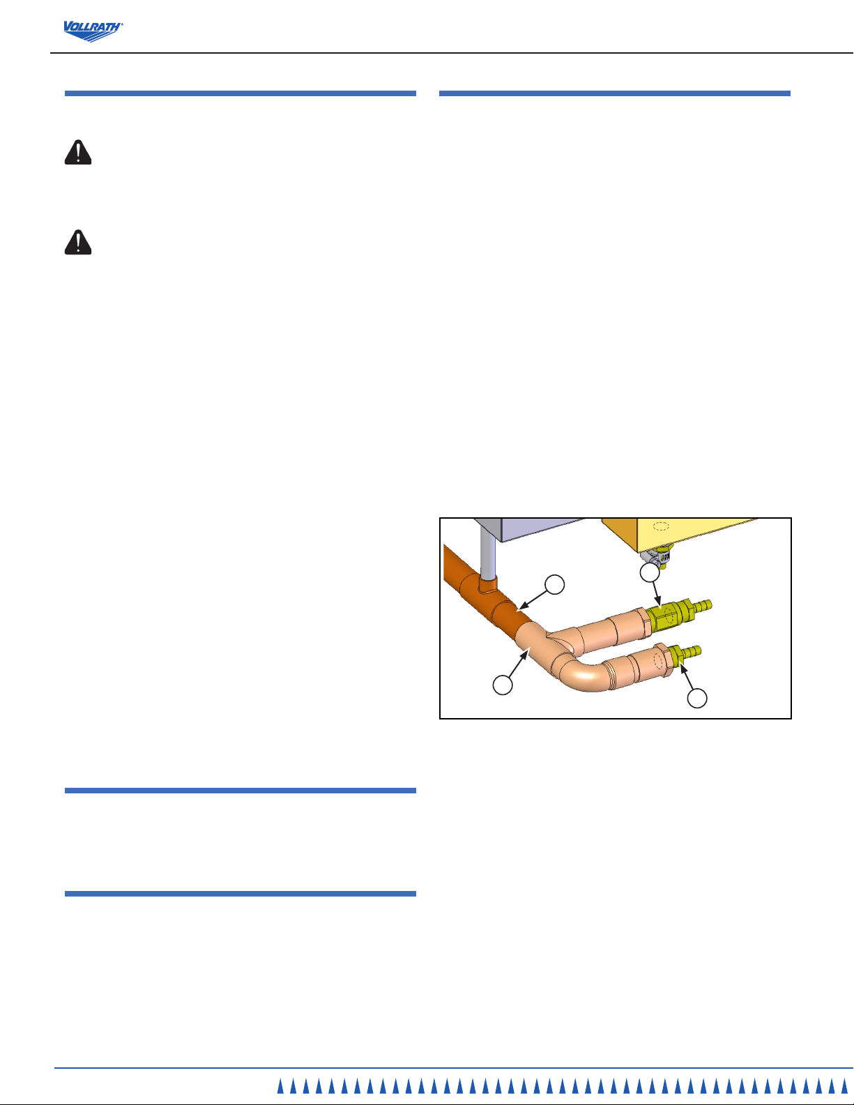
3. If installing this Auto-ll on a Vollrath drain manifold, cut off the pipe cap
from the end of the drain manifold assembly that is on the opposite end
of the main drain valve.
4. Solder the Auto-Fill manifold assembly (A) to the open end of the drain
line (B) from step 2 making sure the auto ll manifold is level with the
existing drain manifold. Figure 1.
Figure 1. Drain Line and Manifold Assembly .
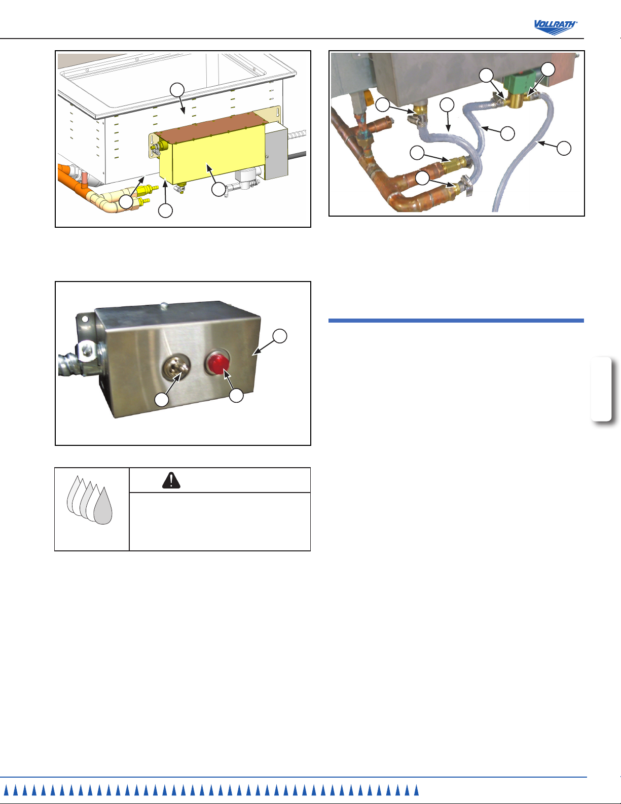
5. For installation with Rectangular Drop-In For initial setup, mount the
Auto-Fill main body water reservoir (B) level to the bottom of any full size
Vollrath hot well (C) unit outer skin. Mark and use appropriate length
fasteners to mount reservoir (B) assembly in a level position (D) to the
bottom of the well assembly (A). See Figure 2.
6. For use with Round Soup Drop-In: Install the reservoir (B) 5/8”
(15 mm) below the bottom of a Vollrath round soup drop in unit outer
skin. See Figure 2.
1. The adjustment procedure above should be used with soup pots with
the understanding that the water level the unit will maintain is the water
level when there is a soup pot in use. The recommended 5/8” (15 mm)”
placement of the reservoir below the soup warmer (In the installation
section above) will maintain water at the water level mark in the well.
However at this level, if a soup insert is placed into the soup warmer that
has water lled to this mark without an insert in place, when inserted the
insert will displace some of the water up the sides of the soup warmer.
Because the water will level out in the entire system, this may cause the
reservoir tank of the auto-ll unit to overow.
B
C
A
D
2
OperatOr’s Manual
Page 3
Countertop Warming and display
C
B
A
D
Figure 4. Solenoid Valve, Flexible Hose, and Fittings.
Figure 2. Water Reservoir and Well Assembly.
10. Using the section of the exible hose (D) coming from the “O” side of the
7. Mount the auto-ll control box (A) at any convenient dry location close to
an access door. See Figure 3.
solenoid (C) connect this hose to the ant-siphon valve (E).
11. Using the section of the exible hose (F) coming from the reservoir tting
(G) to the tting (H).
Start Up and teSting
A
B
C
Figure 3. Control Box, Switch and Light.
WARNING
Water Contamination Hazard.
The overow drain line must not be connected
to any drain. It must be routed to an open drain
leaving a air gap separating the overow drain line
from the top of the open drain reservoir.
8. Using the section of the exible hose marked and/or coming from
outlet (E) side of the water tank, route this line to an OPEN FLOOR
DRAIN. This drain MUST not be directly plumbed to the auto ll unit. This
is done to prevent contamination of the fresh water supply. See Figure 4.
9. Using the section of the exible hose (A) coming from the “IN” or “I” side
of the solenoid (B) connect this hose to your fresh water source. See
Figure 4.
1. Plug the auto-ll control box into a grounded 120 Volt 15 Amp electrical
outlet.
2. Verify the main drain valve is in the CLOSED position to prevent water
from draining out. Be sure the individual well drains are in the OPEN
position to allow water to ll the wells from the drain manifold.
3. Turn the fresh water supply valve on. Start with the valve in the full open
position.
4. Turn on the Auto-ll system using the switch on the control assembly.
The red indicator light should come on indicating power is supplied to the
unit and water should ow into the system.
NOTE: If a continuous stream of water begins to ow out of the
overow tube when lling the unit, stop lling and drain the unit. Close
the water supply valve from step 3 part way to reduce water ow. Rell
unit. Continue this process until water does not ow out of the overow
when lling the unit. It is normal to have small amounts of water ow
out the overow while the unit is lling.
5. The auto-ll system may cycle on and off a few times, with delays,
before the water level is stabilized. The number of cycles and delays are
dependant on water pressure, number of wells lling, etc. Do not attempt
to adjust the water level until the system has fully stabilized. When the
system does not cycle on or off after a full minute, the system should be
stabilized.
6. When the system is stabilized, check the water level in each of the wells.
For proper water level control it is important the hot food unit be level.
Each well should have approximately the same amount of water.
7. If the water level is too low, loosen (do not remove) the screws used
to mount the reservoir assembly. Lift the reservoir assembly up
approximately 1/8”. Retighten the screws. There may again be a delay
before the system begins to ll. Allow the system to stabilize again and
re-check the water level.
8. Continue the adjustment until you have the water level adjusted to the
desired level. The water level should not be adjusted above 1/2” of water.
9. For most efcient heating and performance, use approximately 1/4” of
water in each well.
C
G
F
D
E
H
B
A
ENGLISH
OperatOr’s Manual
3
Page 4

Countertop Warming and display
operation
WARNING
Electrical Shock Hazard.
Keep water and other liquids from entering the
inside of the equipment.
electrical components and cause a short circuit
or an electrical shock. Do not spray water or
cleaning products. Do not use equipment if power
cord is damaged or has been modied.
1. Check the drain valve of the Hot Food Unit. Make sure it is in the closed
position to prevent water from draining out. Generally, the valve is in the
off position when the handle of the valve forms a “T” with the body of the
valve.
2. Turn Auto-Fill control on. Operate the Vollrath Hot Food Table in
accordance with the Operating and Safety Instructions that were
provided with the Hot Food Table.
3. At the end of the serving period, turn the Auto-ll control off before
opening the drain valve for the Hot Food Unit. If the unit is drained with
the Auto-ll on, the unit will continue to ll and will not completely drain.
4. Follow the shut down and cleaning procedures that were sent with the
Hot Food Table. No special cleaning is required for the Auto-ll system.
Liquid could contact the
troUbleShooting chart
Problem It might be caused by Course of Action
No Water in the wells.
Wells are not getting hot enough. There may be too much water in the wells. Change the water level to a maximum depth of 3/8”.
No Water in the wells. The reservoir assembly may be set too low. Loosen the fasteners and raise the assembly.
The water continues to run and the
water ows out the over ow tube.
The wells continue to ll beyond
the desired water level.
Check to make sure there is power supplied to
the Auto-ll unit.
There may be a clog in the drain assembly
preventing water from reaching the oat or the
drain overow may be clogged causing an air
lock in the Auto-Fill reservoir.
The oat switch may be installed incorrectly.
Verify the switch is ON. Verify the water supply valve is open.
Refer to the installation section and be sure all steps were followed
properly.
Make sure drain line is open and water is able to reach the
reservoir. Also, make sure the auto ll system is plugged in and
grounded.
Disconnect power and remove the control box cover on the outside
of the revisor tank. Check to see that the arrow molded into the
white plastic nut portion of the oat switch is pointing DOWN.
Service and repair
There are no user serviceable parts within this appliance. To avoid serious injury or damage, never attempt to repair the equipment or replace a damaged power
cord yourself. Do not send equipment directly to the Vollrath Company. Please contact the qualied professional repair service listed below.
VOLLRATH Technical Service • 1-800-628-0832
4
OperatOr’s Manual
Page 5

Countertop Warming and display
electrical draWing - drop-in aUto-fill ~ 26806
PILOT LIGHT, AMBER - 120V
23255
CONNECTOR ¼" Q-D FEMALE
26737
SWITCH - TOGGLE, F SERIES
17925
CONNECTOR, SNAP SPADE
26555
WIRE 5 16 GA BLACK 6" LONG
WIRE 4 16 GA GREEN 42" LONG
WIRE 3 16 GA WHITE 42" LONG
WIRE 2 16 GA BLACK 42" LONG
WIRE 1 16 GA BLACK 42" LONG
3/8" CONDUIT
26624
WIRE 2
CONNECTOR, RING, #10 STUD, 12-10
26559
WIRE 5
WIRE 4
WIRE 3
WIRE 2
FLOAT SWITCH
23244
WIRE 1
WIRE 1
WIRE NUT, BLACK
22860
WIRE 3
WIRE NUT, BLACK
22860
WIRE NUT, BLACK
22860
WIRE 4
WIRE NUT, BLACK
22860
CONNECTOR, RING, #10 STUD, 12-10
26559
GREEN
ENGLISH
WHEN ASSEMBLED
PIVOT POINT MUST
BE DOWN.
VALVE, AUTO FILL
BLACK
CORD SET, 120V, 5-15 PLUG
26550
WHITE
GREEN
23033
OperatOr’s Manual
5
Page 6

Countertop Warming and display
CONNECTS TO
WATER SUPPLY
CONNECTS TO
FLOOR DRAIN
1
7
5
9
2
8
4
6
3
2
2
2
2
3
3
3
2
10
11
12
12
Spare partS liSt - drop-in aUto-fill ~ 26806
Callout Part Number Description
1 44084 Autoll Water Reservoir Subassembly
2 26681 7/16” - 3/4” Hose Clamp
3 26682 3/8” I.D. Hose
4 23244 Float Switch
5 23033 Solenoid
6 17925 Switch, 120V
7 23255 Pilot Light, Amber, 120V
8 44082 Autoll Solenoid Subassembly, (includes box, hose ttings, power cord, hardware, Ref. 5 and 11)
9 44081 Autoll Water Reservoir, (includes tank, cover Ref. 4 and 12
10 44083 Autoll Control Box, (includes box, conduit, Ref. 6 and 7)
11 23341 Inline Filter, 1/4 NPT
12 23019 Hose Fitting
eXploded vieW - drop-in aUto-fill ~ 26806
6
OperatOr’s Manual
Page 7

Countertop Warming and display
Warranty Statement for the vollrath co. l.l.c.
The Vollrath Company LLC warrants the products it manufactures and distributes against defects in materials and workmanship for a period of one year, except as specically
provided below. The warranty runs 12 months from the date of original installation. (End user receipt)
1. Refrigeration compressors – The warranty period is 5 years.
2. Replacement parts – The warranty period is 90 days.
3. Fry pans and coated cookware – The warranty period is 90 days
4. EverTite™ Riveting System – The warranty covers loose rivets
only, forever.
5. Cayenne® Heat Strips – The warranty period is 1 year plus an
additional 1 year period on heating element parts only.
6. Ultra and Professional Induction Ranges – The warranty period
is 2 years.
7. Mirage and Commercial Induction ranges - The warranty period
is 1 year.
8. ServeWell® Induction Workstations – The warranty period is one
year on the workstation table and 2 years on induction hobs.
9. Slicers – The warranty period is 10 years on gears and 5 years
on belts.
10. Mixers – The warranty period is 2 years.
11. Extended warranties are available at the time of sale.
12. Vollrath – Redco products – The warranty period is 2 years.
13. Optio / Arkadia product lines – The warranty period is 90 days.
14. All non-stick products (i.e. fry pans and surfaces) are 90 days for
the non stick surfaces.
All products in the Jacob’s Pride® collection, including
the following, have a lifetime warranty:
• NSF Certied One-Piece Dishers
• NSF Certied Spoodle® Utensils
• NSF Certied Heavy-Duty Spoons with
Ergonomic Handle
• NSF Certied Heavy-Duty Basting Spoons
• Heavy duty Turners with Ergonomic handle
• One-Piece Tongs*
• Heavy-Duty One-Piece Ladles*
• Nylon Handle Whips
• One-Piece Skimmers
• Tribute®, Intrigue®, and Classic Select®
Cookware*
*Jacob’s Pride® warranty does not cover Kool-Touch®,
non stick coatings and silicone handles.
Items sold having no warranty:
• Meat Grinder Knives
• Light Bulbs in Convection Ovens and
Hot Food Merchandiser
• Oven Door Seals
• Oven Door Glass
• Hot Food Merchandisers / Display Case
Glass
• Calibration and set up of gas equipment
• Slicer / Dicer blades (table top food
prep) – Redco and Vollrath
THIS WARRANTY IS IN LIEU OF ANY OTHER WARRANTIES, EXPRESS OR IMPLIED, INCLUDING ANY IMPLIED WARRANTY OF
MERCHANTABILITY OR FITNESS FOR A PARTICULAR PURPOSE
As The Vollrath Company LLC’s only responsibility and the purchaser’s only remedy, for any breach of warranty, The Vollrath Company LLC will repair or, at its option, replace the
defective product or part without charge, except as otherwise provided below:
• For refrigeration compressors and the second year of the warranty on Cayenne® Heat Strips and mixers, The Vollrath Company LLC will provide the repaired
or replacement part only; and the buyer will be responsible for all labor charges incurred in performing the repair or replacement.
• To obtain warranty service, the buyer will be responsible to return to The Vollrath Company LLC any product (other than gas equipment that is permanently
installed) weighing less than 110 lbs. or located outside of a 50-mile radius of a certied technician designated by The Vollrath Company LLC to perform
warranty repairs. If a Vollrath Technician cannot be contacted check the website for service contact points. (Please refer to the Product Catalogue for weights
and sizes of product)
• No remedy will be available for products that have been damaged by accident, carelessness, improper installation, lack of proper setup or supervision
when required, neglect, improper use, installation or operation contrary to installation and operating instructions or other causes not arising out of defects in
materials or workmanship. At the buyer’s request, The Vollrath Company LLC will repair and or replace such products at a reasonable cost.
• No remedy will be available for slicers where blade has not been sharpened (Refer to owner’s manual for sharpening instructions)
• No remedy will be available for mixers damaged by changing gears while unit is running or overloading, in either case as determined by a Vollrath Certied
Technician
• Warranty work must be authorized in advance by The Vollrath Company LLC. See the operating and safety instructions for each product for detailed
warranty claim procedures.
• No remedy will be available for product returned and found to be acceptable to the product specication.
• No remedy will be available under any warranty not registered as required below.
ENGLISH
LIMITATION OF LIABILITY:
THE VOLLRATH COMPANY LLC SHALL HAVE NO LIABILITY FOR INCIDENTAL OR CONSEQUENTIAL DAMAGES OF ANY KIND,
WHETHER BASED UPON NEGLIGENCE OR OTHER TORT, BREACH OF WARRANTY, OR ANY OTHER THEORY.
Warranty proCedure
OperatOr’s Manual
7
Page 8

On all warranty calls, the following process and information is required:
• All warranty claims will start with a call to Vollrath Technical Service support line.(800-354-1970).
• A technical support professional will work to diagnose the issues, and provide the details for the service solution.
• Name and phone number of person calling
• Business name, street address, city, state and zip
• Model and serial number
• Date of purchase and proof of purchase (Receipt)
• Name of dealer where unit was purchased
NOTE: Vollrath will not accept products sent without the proper procedure being followed.
Important:
TO MAKE A CLAIM FOR ANY REMEDY UNDER THIS WARRANTY, YOU MUST REGISTER YOUR WARRANTY.
register today
ONLINE: Register your warranty on-line now at www.Vollrathco.com
NO WEB ACCESS: If you do not have access to the web, kindly register by completing the warranty registration form and faxing it to The Vollrath Co. LLC ofce in the country of
purchase.
Warranty regiStration
Business name
Key ContaCt name email
street address
City state Zip Code
Country phone Fax
model item numBer
serial numBer - -
operation type
R Limited Service Restaurant R Full Service Restaurant R Bars and Taverns R Supermarket
R Convenience Store R Recreation R Hotel/Lodging R Airlines
R Business/Industry R Primary/Secondary School R Colleges/University R Hospitals
R Long-Term Care R Senior Living R Military R Corrections
reason For seleCting our produCt
R Appearance R Full Service Restaurant R Availability R Sellers Recommendation
R Ease of Operation R Versatility of Use R Price R Brand
Would you liKe to reCeive our Full-line Catalog and remain on our mailing list? R Yes R No
www.vollrathco.com
The Vollrath Company, L.L.C.
1236 North 18th Street
Sheboygan, WI 53081-3201
U.S.A.
Main Tel: 800.628.0830
Fax: 800.752.5620
Technical Services: 800.628.0832
Service Fax: 920.459.5462
Canada Service: 800.695.8560
© 2012 The Vollrath Company, L.L.C.
 Loading...