

Page 1

Model M202 IntelliTec
OPERATORS MANUAL
Manual No. 513666 Rev.1
Page 2

Page 3

Owner’s Manual
For M202 IntelliTec
Continuous Flow Machines
This manual provides basic information about the machine. Instructions and suggestions are
given covering its operation and care.
The illustrations and specifi cations are not binding in detail. We reserve the right to make
changes to the machine without notice, and without incurring any obligation to modify or provide new parts for machines built prior to date of change.
DO NOT ATTEMPT to operate the machine until instructions and safety precautions in this
manual are read completely and are thoroughly understood. If problems develop or questions
arise in connection with installation, operation, or servicing of the machine, contact the company at the following location:
STOELTING Ph: 800-558-5807
502 Hwy. 67
Kiel, WI 53042 Fax: 920-894-7029
© 2013 Stoelting, LLC, All Rights Reserved
Page 4

A Few Words About Safety
Safety Information
Read and understand the entire manual before
operating or maintaining Stoelting equipment.
This manual provides the operator with information
for the safe operation and maintenance of Stoelting
equipment. As with any machine, there are hazards
associated with their operation. For this reason safety
is emphasized throughout the manual. To highlight
specifi c safety information, the following safety defi ni-
tions are provided to assist the reader.
The purpose of safety symbols is to attract your attention to possible dangers. The safety symbols, and
their explanations, deserve your careful attention
and understanding. The safety warnings do not by
themselves eliminate any danger. The instructions
or warnings they give are not substitutes for proper
accident prevention measures.
If you need to replace a part, use genuine Stoelting
parts with the correct part number or an equivalent
part. We strongly recommend that you do not use
replacement parts of inferior quality.
Safety Alert Symbol:
This symbol Indicates danger, warning or caution.
Attention is required in order to avoid serious personal injury. The message that follows the symbol
contains important information about safety.
Signal Word:
Signal words are distinctive words used throughout
this manual that alert the reader to the existence and
relative degree of a hazard.
WARNING
The signal word “WARNING” indicates a potentially
hazardous situation, which, if not avoided, may result
in death or serious injury and equipment/property
damage.
CAUTION
The signal word “CAUTION” indicates a potentially
hazardous situation, which, if not avoided, may result
in minor or moderate injury and equipment/property
damage.
CAUTION
The signal word “CAUTION” not preceded by the
safety alert symbol indicates a potentially hazardous
situation, which, if not avoided, may result in equipment/property damage.
NOTICE
The signal word “NOTICE” indicates information or
procedures that relate directly or indirectly to the
safety or personnel or equipment/property.
Page 5

TABLE OF
CONTENTS
Section Description Page
1 Description and Specifi cations
1.1 Description ..................................................................................................1
1.2 Specifi cations .............................................................................................2
2 Installation Instructions
2.1 Safety Precautions .....................................................................................3
2.2 Receiving the Custard Machine ..................................................................3
2.3 Machine Installation ....................................................................................3
A. Running Line Sets ................................................................................................3
B. Running Electrical Connections ...........................................................................4
C. Plumbing Connections .........................................................................................4
D. Receiving and Installing Remote Condensing Units ............................................5
E. Setting in Place and Making Machine Connections .............................................5
F. Running Product and Setting Pressures ..............................................................6
3 Initial Set-Up and Operation
3.1 Operator’s Safety Precautions ....................................................................9
3.2 Operating Controls and Indicators ..............................................................9
3.3 Sanitizing ....................................................................................................10
3.4 Freeze Down and Operation ......................................................................11
3.5 Mix Information ...........................................................................................12
3.6 Removing Mix from Machine ......................................................................12
3.7 Cleaning the Machine .................................................................................12
3.8 Disassembly of Machine Parts ...................................................................13
3.9 Cleaning the Machine Parts .......................................................................13
3.10 Assembly of Machine .................................................................................13
3.11 Routine Cleaning ........................................................................................14
3.12 Preventative Maintenance ..........................................................................14
3.13 Extended Storage .......................................................................................15
4 Troubleshooting
4.1 Error Codes ................................................................................................17
4.2 Troubleshooting Error Codes ......................................................................17
4.3 Troubleshooting Tables ...............................................................................19
5 Replacement Parts
5.1 Decals and Lubrication ...............................................................................21
5.2 Auger Shaft and Faceplate Parts ...............................................................22
5.3 Hopper Parts ..............................................................................................23
Page 6

Page 7
SECTION 1
DESCRIPTION AND SPECIFICATIONS
1.1 DESCRIPTION
The M202 is continuous fl ow custard machine. It is
equipped with fully automatic controls to provide a uniform product and feature Quick-Freeze technology . This
manual is designed to assist qualifi ed service personnel
and operators in the installation, operation and maintenance of the M202 frozen custard machine.
NOTE
Product breakdown could happen quicker if product
is stored in the freezing cylinders for more than one
hour. After a batch is made, close the fl ow control
and empty the contents of the freezing cylinder.
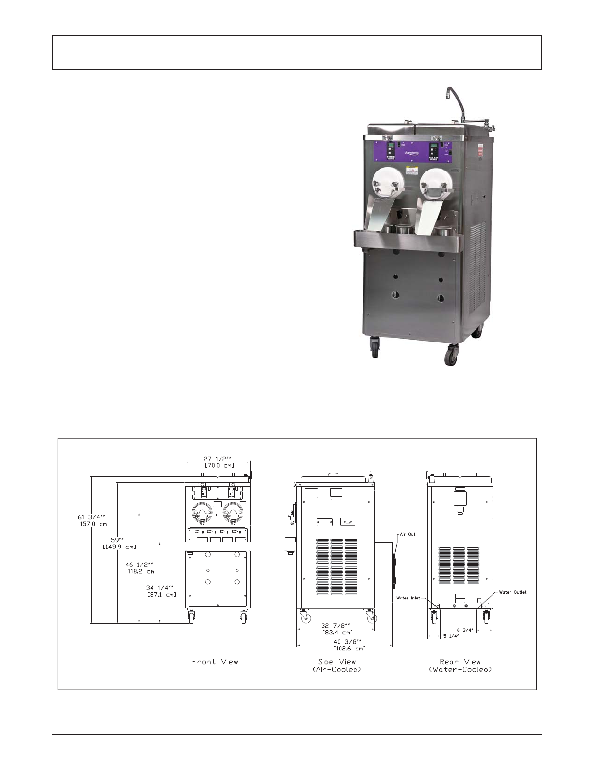
Figure 1-1 Model M202
Figure 1-2 Model M202 Dimensions
Owner’s Manual #513666 Rev.1 1 M202B Model Machines
Page 8

1.2 SPECIFICATIONS
Dimensions
M202B A/C M202B A/C Remote M202B W/C
Machine with crate Machine with crate Machine with crate
width
height
depth
Weight
Electrical
circuit ampacity
(per barrel)
overcurrent protection
device (per barrel)
27-1/2’’
(69,9 cm)
59’’
(149,9 cm)
40-3/8’’
(102,6 cm)
845 lbs
(383,2 kg)
1 PH 3 PH 1 PH 3 PH 1 PH 3 PH
20A 15A 15A 15A 20A 15A
25A 15A 15A 15A 25A 15A
48’’
(121,9 cm)
69-1/4’’
(175,9 cm)
60’’
(152,4 cm)
1100 lbs
(498,9 kg)
27-1/2’’
(69,9 cm)
57-1/2’’
(146,1 cm)
32’’
(81,3 cm)
645 lbs
(292,5 kg)
Drive Motor Two - 2 hp
Air cooled units require one
remote condensing unit
(with compressor) per barrel.
Condensing units #285090
Cooling
Self contained air cooled units
require 6” (15,2 cm) air space
on sides and 24” (60,9 cm) at
the back. They are charged
with R-404A.
and #285091 ship from the
factory with 20 lbs of R-404A
for up to a 50’ line set. Add
1 lb of refrigerant for every
10’ increase to the line set.
Line set max 100’. (Remote
condensers CU-0050 and CU-
0060 do not ship charged and
require 20 lbs of R-404A)
42-1/2’’
(108,0 cm)
67’’
(170,2 cm)
48’’
(121,9 cm)
945 lbs
(428,6 kg)
27-1/2’’
(69,9 cm)
57-1/2’’
(146,1 cm)
32’’
(81,3 cm)
845 lbs
(383,2 kg)
Water cooled units are self
contained and require a
Standard Hose Adapter water
fi tting and a 1/2” OD drain
fi tting for each barrel. They are
charged with R-404A.
42-1/2’’
(108,0 cm)
67’’
(170,2 cm)
48’’
(121,9 cm)
1100 lbs
(498,9 kg)
Hopper Volume Two - 5.4 gallon (20,57 liters)
Remote Condensing Unit (1 per barrel)
Dimensions Condenser
width 37-3/4’’ (95,9 cm)
height 17-1/4’’ (43,7 cm)
depth 28-1/4’’ (71,7 cm)
Weight 222 lbs (100,7 kg)
Electrical
circuit ampacity
overcurrent protection
device
Refrigerant R-404A
Charge 20 lbs. (Charged at Factory)
Refrigerated Line
Sizes
Owner’s Manual #513666 Rev.1 2 M202B Model Machines
1 Phase, 208-230 VAC, 60Hz 3 Phase, 208-230 VAC, 60Hz
20A minimum 15A minimum
25A maximum 20A maximum
Liquid Line - 3/8”
Suction Line - 5/8”
Page 9

SECTION 2
INSTALLATION INSTRUCTIONS
2.1 SAFETY PRECAUTIONS
Do not attempt to operate the machine until the safety
precautions and operating instructions in this manual are
read completely and are thoroughly understood.
Take notice of all warning labels on the machine. The labels have been put there to help maintain a safe working
environment. The labels have been designed to withstand
washing and cleaning. All labels must remain legible for
the life of the machine. Labels should be checked periodically to be sure they can be recognized as warning labels.
If danger, warning or caution labels are needed, indicate
the part number, type of label, location of label, and quantity
required along with your address and mail to:
STOELTING
ATTENTION: Customer Service
502 Hwy. 67
Kiel, Wisconsin 53042
2.2 RECEIVING THE CUSTARD MACHINE
A. Upon arrival, check the entire machine for any
damage that may have occurred during transit.
With the method of packaging used, the machine
should arrive in excellent condition. The carrier
is responsible for all damage in transit, whether
visible or concealed. Do not pay the freight bill
until the machine has been checked for damage.
Have the carrier note any visible damage on the
freight bill. If concealed damage or a shortage is
found later, advise the carrier within 10 days and
request inspection. The customer must place a
claim for damages and/or shortages in shipment
with the carrier. Stoelting cannot make any claims
against the carrier.
B. Remove the top of the crate using a hammer or
pry bar.
C. Remove the eight lag bolts from the machine
using a 1/2” ratchet. Remove the front and rear
crate walls.
D. Remove the four lag bolts located inside the left
and right crate walls using 1/2” ratchet. Remove
the left and right crate walls.
E. Remove the plastic wrapping on the machine.
Remove the lower front and back panel on the
machine.
F . Remove the four lag bolts located inside machine
on the frame with a 9/16” ratchet. Remove the
two lag bolts that hold the skid together with a
9/16” socket.
G. If the machine has the shipping casters or if it is
water-cooled, the casters will be in a box located
in the hopper pan. A set of casters includes two
casters with locks and two casters without locks.
Screw the casters into the threaded holes and
tighten them using a pair of channel locks. After
installing the casters, knock out bottom 4” x 4” of
the machine skid.
NOTE
If the machine does not come with casters, install
the stainless steel legs. The legs are located in the
hopper pan on top of the machine. After installing
the legs, use a pallet jack to move machine into
place.
H. Put front and back panels on the machine.
2.3 MACHINE INSTALLATION
The following instructions are intended for a qualifi ed
electrician/refrigeration specialist. Do not attempt these
procedures unless you are qualifi ed.
CAUTION
Installation MUST be completed by a qualifi ed
electrician/refrigeration specialist
Incorrect installation may cause personal injury,
severe damage to the machine and will void factory warranty.
A. RUNNING LINE SETS
NOTE
If the machine is water-cooled, proceed to “B. Running Electrical Connections”.
Line sets are not supplied with the machine.
The lines sets can be installed prior to receiving the
custard machine.
1 An air-cooled machine requires a remote
condensing unit and line set for each freezing
cylinder. The line sets must be 3/8” for the liquid
line and 5/8” for the suction line. When running
the line sets, each 10’ of vertical rise, install a
p-trap in the suction line. For every horizontal
line set run, pitch the suction line towards the
compressor to assist with oil returning back to
the compressor.
2 After the line set is installed, perform a thorough
leak test. Malfunctions of the equipment due
to leaks in the line set are not covered by the
Stoelting/Ross warranty.
Owner’s Manual #513666 Rev.1 3 M202B Model Machines
Page 10

3 Insulate the suction line with a minimum of 3/8” wall
thickness or the wall thickness required by local
code. In humid areas, use thicker insulation. In
areas that are exposed to extreme temperatures,
insulate the liquid line to prevent excessive
sub cooling or heating of the liquid refrigerant.
Fasten all lines securely along ceilings, walls
and roofs. Avoid creating any type of kink in the
lines. The Stoelting/Ross warranty does not cover
malfunctions or capacity issues with equipment
caused by kinks in the line sets.
4 Use good piping practices when installing line sets.
Seal the ends of the line sets during installation to
prevent exposure to the atmosphere and foreign
objects. Blow the lines out with dry nitrogen to
remove any debris that might be in the line sets.
When running line sets through a wall or roof,
mark the lines to eliminate confusion as to which
line set is running to which cylinder.
Example: Mark the liquid and suction lines with
the respective cylinder number. Facing the front
of the machine, cylinders are numbered left to
right.
5 When brazing the joints, purge dry nitrogen
through the lines to minimize oxidation of copper
inside of the lines. The Stoelting/Ross warranty
does not cover problems with the refrigeration
system that are caused by oxidized material in
the lines.
B. RUNNING ELECTRICAL CONNECTIONS
1 The machine requires a separate electrical
connection for each freezing cylinder. Refer to the
nameplate on the machine for proper electrical
supply. Each freezing cylinder has its own
electrical system and condenser so if one cylinder
fails, the other cylinder will still be operational.
NOTE
An air-cooled machine needs two circuits for each
freezing cylinder, one for the remote condensing
unit and one for the freezing cylinder.
4 Do not turn on the power to the machine or
the condensing unit until the refrigeration lines
have been connected and the system has been
charged with refrigerant. Label the circuit breakers
with information regarding which cylinder and
condensing unit the breaker is designated for to
prevent confusion if power ever needs to be shut
off.
5 When connecting power to the machine, run the
line under the machine and through the bottom
of the electrical box. Remove the electrical box
cover by loosening the four screws. The screws
do not have to be removed. Connect the power
to the terminal strip. The terminal strip is labeled
L1, L2, L3, and GND. After connections are made,
place the cover on the electrical box, but do not
tighten the cover (for single-phase machines the
cover can be tightened). The electrical box may
need to be accessed when checking for proper
rotation of the motor.
C. PLUMBING CONNECTIONS
1 On water-cooled machines, the water inlet is a
standard garden hose connection and the water
outlet is 5/8” OD copper tubing. The connections
are located at the back of the machine. Remove
the rear panel to access the connections. Run
the plumbing under the machine frame. Watercooled machines use approximately 3 gallons of
75°F water per minute when the compressor is
operating. The machine does not use any water
when not in use.
2 The machine is equipped with a dipping trough
that requires a water inlet line and a drain line.
The water inlet has 1/2” NPT close nipple fi tting.
Install a shutoff valve in the water inlet line. The
drain connection is 1-1/2”. Run a drain line from
the trough to a drain on the fl oor. Leave enough
slack in the drain line so that the lower front panel
can be easily removed for service.
A water-cooled machine needs one circuit for each
freezing cylinder.
2 The electrical boxes are located behind the lower
front panel. Labels indicate which cylinder each
electrical box powers. No pigtails are supplied
with the machine or condensing unit.
3 If the condensing unit is on the roof or ground,
a quick disconnect box needs to be installed to
provide power.
Owner’s Manual #513666 Rev.1 4 M202B Model Machines
Page 11

D. RECEIVING AND INSTALLING REMOTE
CONDENSING UNITS
NOTE
The remote condensing units may be sent prior to
delivery of the freezer.
The freezer requires one remote condensing unit
per cylinder.
Remote condenser models 285090 and 285091
are shipped from the factory charged with 20 lbs
of R404a refrigerant.
1 Upon arrival, check the entire remote condenser
units for any damage that may have occurred
during transit. With the method of packaging used,
the remote condensers should arrive in excellent
condition. The carrier is responsible for all damage
in transit, whether visible or concealed. Do not
pay the freight bill until the remote condenser
units have been checked for damage. Have the
carrier note any visible damage on the freight
bill. If concealed damage or a shortage is found
later, advise the carrier within 10 days and request
inspection. The customer must place a claim for
damages and/or shortages in shipment with the
carrier. Stoelting cannot make any claims against
the carrier.
2 Remove cardboard covering off the condensing
units.
3 Place the condensing units in their predetermined
location, either on the roof or on the ground. A
crane or forklift will be needed if the units will be
placed on a roof. The condensing units weigh
approximately 200 lbs. each.
4 Using ratchet with a 1/2” socket, remove the two
lag bolts that secure the condensing unit to the
pallet.
5 Place the condensing units on 4” x 4” treated
wood or similar material so that the units are not
sitting directly on the ground or the roof. Secure
the condensing units to the 4” x 4” using lag
bolts. Adhere to all local, state, and federal codes
governing this type of installation. Some areas
have specifi c “hurricane-proof” requirements
for roof installations. Allow at least 3 feet of
clearance on the air intake and discharge sides
of the condensers. Do not set the condensers
so that one is blowing air directly into the other
condensing unit. The ideal set up is to have all
the condensing units set in a row (Fig. 2-1).
6 Braze the suction line and liquid line from the
line sets to the condensing unit. When brazing,
wrap the shut off valve with a cold wet rag. If the
valve is not wrapped, damage to the valve may
result. When installing the suction line, angle it
towards the condensing unit so that oil can fl ow
back towards the compressor.
7 Use good piping practices. Keep pipes as clean as
possible. Do not let any debris or copper shavings
get inside system otherwise the refrigeration
valves may not work properly.
E. SETTING IN PLACE AND MAKING MACHINE
CONNECTIONS
1 Roll the machine into the desired location. Leave
adequate space around the machine for the
removal of service panels. Remove the left, right,
back and lower front service panels.
NOTE
After the refrigeration lines are connected, aircooled machines cannot be moved.
2 Use a pallet jack or fl oor jack to lift the front of the
machine, remove the two shipping casters with
a pair of channel locks, and install the stainless
steel legs. Make sure the legs are adjusted all the
way in, and screw two of the legs into the frame.
Secure them tightly using channel locks. Repeat
with the back of the machine.
NOTE
If the machine is water-cooled, casters are standard
with machine.
3 Accurate leveling is necessary to ensure
proper operation. Place a bubble level on top
of the machine at each corner to check for level
condition. If adjustment is necessary, level the
machine by turning the bottom part of each leg
or caster in or out.
To fi nish installing a water-cooled machine,
proceed to “F. Running product and setting
pressures for the custard machine”.
Figure 2-1 Remote Condenser Installation
(Top View)
Owner’s Manual #513666 Rev.1 5 M202B Model Machines
Page 12

4 Connect the refrigeration lines from the line sets
to the machine. Access the machine from the
left or right service panel. Use caution when
connecting the lines. Connect the suction line fi rst
then connect the liquid line. Run the refrigeration
lines under the machine. There is approximately
6” of clearance between machine and the fl oor.
The stainless steel legs are adjustable and can
raise the machine up to 7” off the fl oor if necessary .
Wrap the suction solenoid in a cold wet rag when
soldering to prevent damage to the solenoid. Also,
be aware of the electrical conduit inside custard
machine while soldering the refrigeration lines.
A liquid line dryer is supplied with the machine
and should be the last connection made in the
system. Use good piping techniques to keep the
system clean. Do not leave the lines open and
exposed for a long period.
5 After fi nishing the refrigeration connections,
connect power to the machine. Refer to
“B. Running Electrical Lines” for the proper
procedures. Check the rotation of the beater
shaft. When looking at the machine from the
front, the shaft needs to turn counterclockwise.
If the shaft is turning the wrong direction, shut off
power to the cylinder and switch the L1 and L3
wires. Check rotation again to verify the shaft is
rotating counterclockwise. Once verifi ed, tighten
the screws on the electrical box cover.
If the machine is single phase and the beater
shaft rotation is clockwise, then complete one
of the following procedures. Check rotation after
each procedure.
A. Change programming on variable speed drive
to reverse motor.
B. Change the T1 and T3 output leads going to
the motor from the drive.
C. Change the leads inside the motor electrical
box.
6 Use good refrigeration practices to charge the
system with the required charge. Air-cooled
machines require 20 lbs of refrigerant per cylinder
and water-cooled machines require 8 lbs of
refrigerant per cylinder. Make sure the suction
solenoid is energized and that the shut off valves
are open.
NOTE
Air-cooled units require one remote condensing
unit (with compressor) per barrel. Condensing
units #285090 and #285091 ship from the factory
with 20 lbs of R-404A for up to a 50’ line set. Add
1 lb of refrigerant for every 10’ increase to the line
set. Line set max 100’. Water-cooled machines are
factory charged.
F. RUNNING PRODUCT AND SETTING PRESSURES
FOR THE CUSTARD MACHINE
NOTE
Complete the Custard Machine Start-Up and T raining Checklist located with the spare parts kit or in
the back of this manual and send it to Stoelting.
1 Remove all spare parts from the hopper before
running product. Unwrap the parts and check for
damage. Refer to the list in the back of this manual
to make sure no parts are missing. The cylinders
need to be under a load to set the pressures. If
custard is not available, RV antifreeze can be
used as an alternative. Mix the RV antifreeze in a
concentration of 1 part antifreeze to 1 part water.
If RV antifreeze is used, the pressures will need
to be rechecked when custard mix is available.
The RV antifreeze will indicate that the system
is functioning correctly.
2 Disassemble, clean and sanitize each freezing
cylinder. Refer to the Section 3 for proper
instructions.
3 After assembling and sanitizing the machine, add
custard mix to the hopper. Follow the instructions in
the Section 3 to start freezing the custard (run one
cylinder at a time to set the pressures). Connect
gauges to the suction line and the discharge line.
When product starts coming out of the faceplate,
locate the low pressure gauge on the front of the
machine and set the AXV to 30 psi. Remove the
white plastic cap from the AXV and turn the valve
counterclockwise to decrease the pressure or
clockwise to increase the pressure. Turn the valve
1/4 turn at a time and wait at least 1 minute before
making another adjustment. Connect a gauge
to the suction line at the compressor and make
sure the pressure is 25 psi. Adjust the crankcase
pressure regulator (CPR) if the pressure is not
correct. Remove threaded brass cap on the front
of the CPR and adjust the valve with a 5/16”
Allen wrench. Connect a gauge to the suction
line at the hopper and adjust the hopper EPR to
53-57 psi.
4. Check the faceplate to see if the custard is at the
desired texture and temperature. The standard
normal serving temperature of frozen custard
coming out of the machine is 18°-21°F.
Owner’s Manual #513666 Rev.1 6 M202B Model Machines
Page 13

5. Set the pressures for the remaining cylinders.
NOTE
If the machine is water-cooled, the discharge pressure was already set at the factory. Run custard
mix through the machine to double-check and
fi ne-tune the discharge pressure for the particular
mix being used.
The remote condenser unit has a head pressure
control set for 245 psi.
Custard mixes that use an extract fl avoring will run
differently . T ry different pressure settings by adjusting the AXV. Adjust the pressure setting between
28-32 psi (the machine will not operate correctly if
the AXV is set lower than 28 psi).
6. Set the lemon ice AXV on the right side of the
machine. With the system still running product,
turn the lemon ice switch on. The AXV is located
behind the cylinder in front of the machine. Set
the lemon ice AXV for 38-42 psi.
7. When testing is done, take the cylinders apart
and clean the custard machine. Refer Section 3
for details.
Owner’s Manual #513666 Rev.1 7 M202B Model Machines
Page 14

Owner’s Manual #513666 Rev.1 8 M202B Model Machines
Page 15

SECTION 3
INITIAL SET-UP AND OPERATION
3.1 OPERATOR’S SAFETY PRECAUTIONS
SAFE OPERATION IS NO ACCIDENT; observe these
rules:
A. Know the machine. Read and understand the
Operating Instructions.
B. Notice all warning labels on the machine.
C. Wear proper clothing. Avoid loose fi tting garments,
and remove watches, rings or jewelry that could
cause a serious accident.
D. Maintain a clean work area. Avoid accidents by
cleaning up the area and keeping it clean.
E. Stay alert at all times. Know which switch, push
button or control you are about to use and what
effect it is going to have.
F . Disconnect electrical cord for maintenance. Never
attempt to repair or perform maintenance on the
machine until the main electrical power has been
disconnected.
G. Do not operate under unsafe operating conditions.
Never operate the machine if unusual or excessive
noise or vibration occurs.
3.2 OPERATING CONTROLS AND INDICATORS
Before operating the machine, it is required that the operator know the function of each operating control. Refer
to Figure 3-1 for the location of the operating controls on
the machine.
WARNING
Moving machinery can grab, mangle and dismember. Place the Freezing Cylinder Off/On switch in
the OFF position before disassembling for cleaning
or servicing.
A. Freezing Cylinder Off/On
The Freezing Cylinder OFF/ON switch is a two
position toggle switch used to supply power to the
freezing cylinder control circuit. When the switch
is in the OFF position, the freezing cylinder’s
refrigeration system and auger will not operate.
When the switch is in the ON position, the freezing
cylinder will be operational.
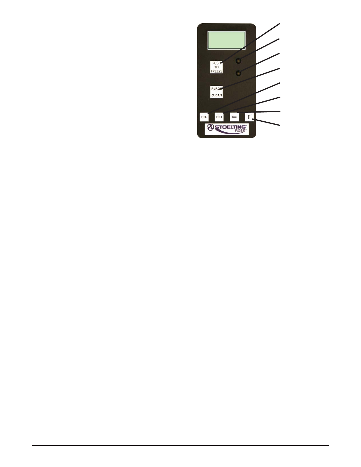
IntelliT ec Control
(See Figure 3-2)
Figure 3-1 Machine Controls
Freezing
Cylinder
Off/On
Product
Selector
Switch
Owner’s Manual #513666 Rev.1 9 M202B Model Machines
Page 16
B. Product Selector Switch
The product selector switch changes the
refrigeration profi le of the right freezing cylinder
to allow two different products to be made. Before
the machine is in ready mode, this switch can be
moved to the desired profi le.
C. PUSH TO FREEZE Button
The PUSH T O FREEZE button is used to initiate
the run mode. To start the machine, place the
Freezing Cylinder OFF-ON switch in the ON
position and press the PUSH TO FREEZE button.
D. LEDs
The membrane switch features two lights; a green
LED and an amber LED. The green LED will fl ash
when the freezing cylinder is near ready mode
and stay lit during ready mode. The amber LED
is lit during standby, purge and clean modes.
NOTE
If the machine enters an error condition, alternating green and amber lights will fl ash. The LCD will
display an error. Turn the Freezing Cylinder OFFON switch to the OFF position, correct the problem
(Refer to T roubleshooting in Section 4) and turn the
machine back on.
E. PURGE/CLEAN Button
PURGE Mode - When the PURGE/CLEAN
button is pressed, the auger will rotate. A PURGE
message will display on the screen along with a
5 minute timer. Hopper refrigeration will continue
to run. When the timer gets to 0:00 and no other
buttons are pressed, the machine will go into
standby mode.
CLEAN Mode - During PURGE mode, if the
PURGE/CLEAN button is pressed and held for 3
seconds, the CLEAN mode will begin. The auger
will continue to rotate and hopper refrigeration will
stop.
F. Mix Low Light Indicator
The MIX LOW message will appear on the
LCD display to alert the operator to a low mix
condition. The message will display when there is
approximately one gallon of mix left in the hopper.
When the MIX LOW message is displayed, refi ll
hopper immediately.
Push to Freeze
Green LED
Amber LED
Purge/Clean
Button
SEL Button
SET Button
Left Arrow Button
Up Arrow Button
Figure 3-2 IntelliTec Control
NOTE
Failure to refi ll hopper immediately may result in
operational problems.
G. Menu Navigation Buttons
The Menu Navigation Buttons are primarily used
for machine calibration.
Selection Button (SEL) The SEL button is not
functional in the normal operation mode. This
button is only used by service technicians for
machine calibration.
Set Button (SET) The SET button is not functional
in the normal operation mode. This button is
only used by service technicians for machine
calibration.
Left Arrow Button () Pressing any button on
the control panel will automatically illuminate the
display . The backlight will turn off several seconds
after use. T o keep the display constantly lit, press
and hold the left () button for fi ve seconds. The
backlight function can be reset to normal operation
in the same manner.
Up Arrow Button (
functional in the normal operation mode. This
button is only used by service technicians for
machine calibration.
H. Front Door Safety Switch
The front door safety switch prevents the auger
from turning when the front door is removed. The
switch is open when the door is not in place and
closed when the door is properly installed.
) The button is not
Owner’s Manual #513666 Rev.1 10 M202B Model Machines
Page 17

3.3 SANITIZING
Sanitizing must be done after the machine is cleaned and
just before the hopper is fi lled with mix. Sanitizing the night
before is not effective. However , you should always clean
the machine and parts after each use.
E. Pour the sanitizer into the hopper.
NOTE
A small amount of sanitizer may drain into the
bucket with the fl ow control shut and may seep out
of the rear seal.
THE UNITED STATES DEPARTMENT OF AGRICUL TURE AND THE FOOD AND DRUG ADMINISTRA TION REQUIRE THA T ALL CLEANING AND
SANITIZING SOLUTIONS USED WITH FOOD
PROCESSING EQUIPMENT BE CERTIFIED FOR
THIS USE.
When sanitizing the machine, refer to local sanitary regulations for applicable codes and recommended sanitizing
products and procedures. The frequency of sanitizing
must comply with local health regulations.
Mix sanitizer according to manufacturer’s instructions to
provide a 100 parts per million strength solution. Mix sanitizer in quantities of no less than 2 gallons (7.5 liters) of
90° to 1 10°F (32° to 43°C) water. Allow sanitizer to contact
the surfaces to be sanitized for 5 minutes. Any sanitizer
must be used only in accordance with the manufacturer’s
instructions.
In general, sanitizing may be conducted as follows:
A. Prepare Stera-Sheen Green Label Sanitizer
or equivalent according to manufacturer’s
instructions to provide a 100ppm strength solution.
Mix the sanitizer in quantities of no less than 2
gallons of 90° to 110°F (32° to 43°C) water. Any
sanitizer must be used only in accordance with
the manufacturer’s instructions.
B. Place the tapered end of the fl ow valve into the
hopper drain hole with the arm pointing towards
the left. Connect the fl ow control rod to the fl ow
valve and the fl ow valve arm (Fig. 3-3).
C. Make sure the fl ow control valve is shut by turning
the control knob counterclockwise to the 12:00
position.
D. Place a bucket under the slide.
F. Place the Freezing Cylinder OFF-ON switch in
the ON position and press the PURGE/CLEAN
button. The display will read PURGE.
G. Press and hold the PURGE/CLEAN button for 3
seconds. The display will read CLEAN and a 10
minute timer will start.
H. Turn the fl ow control knob fully open (clockwise)
to drain the sanitizer from the freezing cylinder.
I. Clean sides of hopper, fl ow valve and underside
of hopper cover using a sanitized soft bristle brush
dipped in the sanitizing solution.
J. When the sanitizer has drained from the hopper,
press and hold the PURGE/CLEAN button for
3 seconds to stop the auger. Allow the freezing
cylinder to drain completely.
K. Shut off the fl ow control valve by turning the
fl ow control knob counterclockwise to the 12:00
position.
3.4 FREEZE DOWN AND OPERATION
This section covers the recommended operating procedures to be followed for the safe operation of the machine.
A. Sanitize just prior to use.
NOTE
Make sure the fl ow control assembly is in place
before adding mix and that the fl ow control knob is
set to the 12:00 position.
B. Fill the hopper with pre-chilled (40°F or 4°C) mix.
C. Place the FREEZING CYLINDER switch in the
ON position. The display will read STANDBY
MODE.
D. Press the PUSH TO FREEZE button. The display
will read CUST ARD and a bar on the second line
will start to fi ll. On the right cylinder the product
type can be changed by moving the Product
Selector switch to the Lemon Ice position.
NOTE
The Product Selector switch can be changed until
the READY message is displayed on the second
line.
E. When the display reads CUSTARD READY, the
freezing cylinder is at the correct temperature
(Fig. 3-4).
F. Open the front gate.
Figure 3-3 Flow Control Assembly
Owner’s Manual #513666 Rev.1 11 M202B Model Machines
Page 18

Figure 3-5 Proper Flow
Figure 3-4 Custard Mode
G. Turn the fl ow control knob clockwise to the 2:00
position. A small amount of mix and remaining
sanitizer will drain from the machine.
H. Turn the fl ow control knob to the 1:00 position.
After a few minutes a ribbon of product starts to
form.
I. Adjust the fl ow control knob until the product
fl ow fi lls the faceplate outlet and is at the desired
texture (Fig. 3-5). The fl ow control knob setting
will be different for each type of product.
NOTE
Adjustments take up to 1 minute before a noticeable
difference is seen in the product.
NOTE
A high-pitched noise from the freezing cylinder is an
indication that there is not enough mix entering the
barrel. Slowly turn the fl ow control knob clockwise
to increase the fl ow. It can take up to 1 minute for
the adjustment to stop the noise.
3.5 MIX INFORMATION
Mix can vary considerably from one manufacturer to
another. Differences in the amount of butterfat content
and quantity and quality of other ingredients have a
direct bearing on the fi nished frozen product. A change
in machine performance that cannot be explained by a
technical problem may be related to the mix.
Proper product serving temperature varies from one
manufacturer’s mix to another. When checking the temperature, stir the thermometer in the frozen product to
read the true temperature.
Old mix or mix that has been stored at elevated tempera-
tures will produce poor-quality product with a bad taste
and unacceptable appearance. T o retard bacteria growth
in dairy based mixes, the best storage temperature range
is between 36° to 41°F (2.2° to 5°C).
3.6 REMOVING MIX FROM MACHINE
To remove the mix from the machine, refer to the following steps. Make sure the gate on the faceplate is open.
A. Press the PURGE/CLEAN button. The display
will read PURGE.
B. Press and hold the PURGE/CLEAN button for 3
seconds. The display will read CLEAN and a 10
minute timer will start.
C. Open the fl ow control valve fully by turning the
fl ow control knob clockwise until the pointer is
near the 12:00 position.
D. After the hopper and freezing cylinder have
drained, place the Freezing Cylinder OFF-ON
switch in the OFF position.
3.7 CLEANING THE MACHINE
NOTE
The frequency of cleaning the machine and machine parts must comply with local health regulations.
After the mix has been removed from the machine, the
machine must be cleaned. To clean the machine, refer
to the following steps:
A. Place a container under the slide of the faceplate.
Fill the hopper with 2 gallons (7.5 liters) of tap
water.
B. Place the Freezing Cylinder OFF-ON switch in the
ON position. Press the PURGE/CLEAN button.
The display will read PURGE.
Owner’s Manual #513666 Rev.1 12 M202B Model Machines
Page 19

C. Press and hold the PURGE/CLEAN button for 3
seconds. The display will read CLEAN and a 10
minute timer will start.
D. When the water has drained, place the switch in
the OFF position. Allow the freezing cylinder to
drain completely.
E. Prepare Stera-Sheen or equivalent cleaner in
2 gallons of 90° to 110°F (32° to 43°C) water
following the manufacturer’s instructions. Repeat
steps A through D using the cleaning solution.
3.8 DISASSEMBLY OF MACHINE PARTS
Inspection for worn or broken parts should be made each
time the machine is disassembled. All worn or broken
parts should be replaced to ensure safety to both the
operator and the customer and to maintain good machine
performance and a quality product. Frequency of cleaning
must comply with local health regulations.
T o disassemble the machine, refer to the following steps:
B. Place all parts in the solution and clean with
provided brushes.
C. Wash the hopper and freezing cylinder with the
Stera-Sheen solution and brushes provided.
D. Wash the rear seal surfaces on the inside of the
freezing cylinder with the Stera-Sheen solution.
E. Rinse all parts with clean 90° to 110°F (32° to
43°C) water.
NOTE
If the machine is not going to be immediately operated, store the faceplate in a clean and sanitized
container in a cooler.
3.10 ASSEMBLY OF MACHINE
T o assemble the machine parts, refer to the following steps:
NOTE
Petrol Gel sanitary lubricant or equivalent must be
used when lubrication of parts is specifi ed.
CAUTION
Hazardous Moving Parts
Revolving auger shaft can grab and cause injury.
Place the Freezing Cylinder OFF-ON switch in the
OFF position before disassembling for cleaning or
servicing.
A. Remove the fl ow control rod and fl ow control
valve from the hopper by pulling straight up.
C. Remove the slide from the faceplate and remove
the faceplate.
D. Remove the front wear bushing.
F. Remove the auger assembly from the machine.
Pull the auger out of the freezing cylinder slowly .
As the auger is being pulled out, carefully remove
each of the blades and springs.
G. Keep the rear of the auger shaft tipped up once
it is clear of the machine to avoid dropping rear
seal.
H. Remove the rear seal.
I. Wipe socket lubricant from the drive end (rear)
of the auger with a cloth or paper towel.
NOTE
The United States Department of Agriculture and
the Food and Drug Administration require that lubricants used on food processing equipment be certifi ed for this use. Use lubricants only in accordance
with the manufacturer’s instructions.
A. Install the rear seal onto the auger dry, without
lubrication.
B. Lubricate the auger drive (rear) with a small
amount of spline lubricant. A small container of
spline lubricant is shipped with the machine.
C. Install two of the springs and auger blades onto
the rear of the auger and insert part way into
machine barrel. Rotate auger so another spring
and blade can be placed onto the shaft.
D. Install the remaining auger blades, push the auger
into the machine barrel and rotate slowly until the
auger engages the drive shaft (Fig. 3-6).
3.9 CLEANING THE MACHINE PARTS
Place all loose parts in a pan or container and take to the
wash sink for cleaning. To clean machine parts refer to
the following steps:
A. Prepare Stera-Sheen or equivalent cleaner in 2
gallons of 90° to 110°F (32° to 43°C) water.
Figure 3-6 Installing Auger Blades
Owner’s Manual #513666 Rev.1 13 M202B Model Machines
Page 20
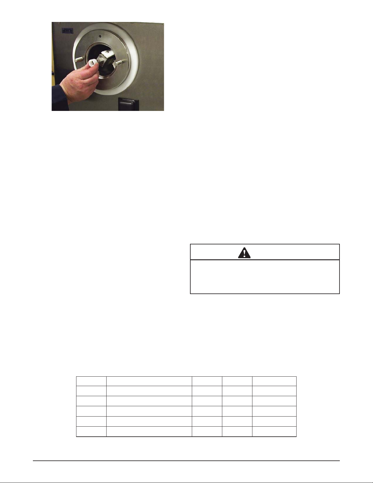
Figure 3-7 Install Front Wear Bushing
E. Lubricate the inside and outside of the front wear
bushing with Petrol Gel and install it onto the
auger (Fig. 3-7).
F. Install the large o-ring onto the faceplate and
install the faceplate onto the machine.
G. Install slide, hopper cover and drain tray.
3.11 ROUTINE CLEANING
T o remove spilled or dried mix from the machine exterior ,
wash in the direction of the fi nish with warm soapy water
and wipe dry. Do not use highly abrasive materials, as
they will mar the fi nish.
3.12 PREVENTATIVE MAINTENANCE
It is recommended that a maintenance schedule be followed to keep the machine clean and operating properly .
A. DAILY
Disassemble and Clean
The frequency of cleaning the machine and parts must
comply with local health regulations. Refer to the previous
sections for proper disassembly and cleaning instructions.
Lubricate Front Wearguard
Petrol Gel sanitary lubricant or equivalent must be used
when lubrication of parts is specifi ed. Apply a thin fi lm of
sanitary lubricant to the inside and outside of the front
wearguard.
Inspect Parts
Inspection for worn or broken parts should be made each
time the machine is disassembled. All worn or broken
parts should be replaced to ensure safety to both the
operator and the customer and to maintain good machine
performance and a quality.
Lubricate Back End of the Auger
Lubricate the rear of the auger with a small amount of
spline lubricant.
B. WEEKLY
Clean Inside Of Machine
Remove all side panels and clean the inside of the machine. Wipe any custard that may have dripped onto the
inner panels with a damp soapy towel. Wash the drain tray .
C. MONTHLY
Clean Condenser Coils (And Filters If Applicable)
The coils on the hopper, dipping cabinet and remote condenser need to be cleaned to ensure proper airfl ow. Use
compressed air to clean the condensers. Blow the air in
the opposite direction of the normal airfl ow.
C. QUARTERLY
Replace Barrel Parts According To Schedule
Follow the Parts Replacement Schedule below to keep
the machine operating properly.
D. ANNUALLY
WARNING
High voltage will shock, burn or cause death. Turn
off and lock out main power disconnect before
servicing. Do not operate machine with panels
removed.
Replace Barrel Parts
Follow the Parts Replacement Schedule below to keep
the machine operating properly.
Part Description 3 Months Annually Qty per Barrel
C-2000-50Spring X 10
C-2000-51Blade X 10
SL-0010 Seal - Beater Shaft X 1
149014 Bushing - Front Auger Support X 1
625174 O-Ring - Front Door X 1
Figure 3-8 Parts Replacement Schedule
Owner’s Manual #513666 Rev.1 14 M202B Model Machines
Page 21

Drive Belt Wear and Tension
Inspect the drive belts for wear. Check for wear marks
from the belts rubbing on the pulley . Use a Burroughs Belt
Tension Gauge to set the tension for the drive belt. Set
the belt tension to 40-50 lbs. If an adjustment is necessary ,
loosen the four motor plate retaining nuts, adjust the belt
tension then retighten the four nuts.
3.13 EXTENDED STORAGE
Refer to the following steps for storage of the machine
over any long shutdown period:
A. Turn the Freezing Cylinder OFF-ON switch to the
OFF position.
B. Disconnect (unplug) from the electrical supply
source.
C. Clean thoroughly with a warm water detergent all
parts that are exposed to the mix. Rinse in clean
water and dry parts. Do not sanitize.
NOTE
Do not let the cleaning solution stand in the hopper
or in the machine barrel during the shutdown period.
D. Remove, disassemble and clean the faceplate,
fl ow control assembly and auger parts. Place the
auger blades and the front auger wear bushing in
a plastic bag with a moist paper towel to prevent
them from becoming brittle.
Owner’s Manual #513666 Rev.1 15 M202B Model Machines
Page 22

Owner’s Manual #513666 Rev.1 16 M202B Model Machines
Page 23

SECTION 4
TROUBLESHOOTING
4.1 ERROR CODES
When the machine experiences a problem, one of the
following error codes will be displayed on the control
panel. Each error code directs you to the system location
of the malfunction.
ERROR CODE MALFUNCTION
1 Soft
2 High Torque
3 Extended Run Time
4 Clean
5 Barrel Sensor
6 Hopper Sensor
7 Drive Motor
8 Cab Sensor
9 High Pressure Cutout
10 Auxiliary Sensor
12 Hopper Sensor
13 Hopper Sensor
To return the machine to normal operation, any error
causing condition must be corrected and the Freezing
Cylinder Off/On switch must be placed in the OFF position and back in the ON position before the machine will
return to normal operation.
4.2 TROUBLESHOOTING ERROR CODES
Error Code 1 - Soft Error
The Soft Error (E1) is an internal control board error
that is logged for future analysis. The refrigeration
is never stopped and the machine will continue
to operate normally.
Error Code 2 - High Torque
If the control panel displays a High Torque Error
(E2), the drive motor is running at a high load for 10
or more seconds. Place the Freezing Cylinder Off/
On switch in the OFF position, wait until the product
in the barrel thaws to a reasonably soft consistency
and return the switch to the ON position. If the
error persists, contact your Authorized Stoelting
Distributor for further assistance.
Error Code 3 - Run Time
The Run Time Error (E3) occurs when the
compressor runs continuously for an extended
period. This error could happen if the cutout
value is not attained during “Standby Mode” or if
the “Ready” signal does not come on in “Custard
Mode” or “Italian Ice Mode”.
This error is generally caused by very low mix
levels in the hopper or from product breakdown.
Check the mix in the hopper. If the level mix is
low, add mix. If there is a possibility that the mix
has broken down, clean and sanitize the machine
and replace the mix with fresh product.
Ice crystals in the hopper can clog the mix inlet
system and prevent mix from entering the freezing
cylinder. Thoroughly thaw mix per manufacturer’s
recommendations. T o check for ice crystals, pour
a small amount of product from the mix container
through a clean and sanitized sieve or strainer.
If ice crystals are in the mix, check temperature
of the walk-in cooler where the mix is stored.
If the error persists after attempting to clear it,
contact your Authorized Stoelting Distributor for
further assistance.
Error Code 4 - Clean
If the machine is left in the Clean Mode for more
than 10 minutes, the control panel will display a
Clean Error (E4). This condition does not refl ect a
problem with the machine itself. The Clean Error
has been programmed into the controller as a
safeguard to protect the machine from potential
damage caused by the machine being accidentally
left in “Clean Mode”. The control will attempt to
restart itself after 5 minutes. The display will then
fl ash and read Restart. T o immediately clear the
Clean Error, place the Freezing Cylinder Off/On
switch in the OFF position and back in the ON
position. After the Clean Error has been cleared,
the machine will start a refrigeration cycle to
protect the product in case the clean button was
pressed by mistake.
Owner’s Manual #513666 Rev.1 17 M202B Model Machines
Page 24

Error Code 5 - Freezing Cylinder Sensor
The Freezing Cylinder Sensor Error (E5) indicates
a failure of the freezing cylinder sensor or if the
sensor is out of range. If the control panel displays
an E5, place the Freezing Cylinder Off/On switch
in the OFF position and back in the ON position.
If the error persists, contact your Authorized
Stoelting Distributor for further assistance.
NOTE
When the machine encounters a Freezing Cylinder
Sensor Error, it will continue to run using preset
timers. This mode will allow the freezing cylinder
to continue making product until it can be serviced.
Error Code 6 - Hopper Sensor
The Hopper Sensor Error (E6) will not occur on
an M202 machine.
Error Code 7 - Drive Motor
If the control panel displays a Drive Motor Error
(E7), the control does not sense current coming
from the drive motor. Place the Freezing Cylinder
Off/On switch in the OFF position and back in
the ON position. If the error persists, contact
your Authorized Stoelting Distributor for further
assistance.
Error Code 8 - Cab Sensor
A Cab Sensor Error (E8) will not occur on an
M202 machine.
Error Code 9 - High Pressure Cutout
High Pressure Cutout Errors (E9) are usually
caused by a dirty or ineffi cient condenser. If the
control panel displays an E9 on an air cooled
machine, check for proper air clearance around
the condenser. In a water cooled machine, check
that the water is not shut off. If the error persists,
contact your Authorized Stoelting Distributor for
further assistance.
Error Code 10 - Auxiliary Sensor
An Auxiliary Temperature Sensor Error (E10)
occurs if the temperature sensor on the control
board fails. Place the Freezing Cylinder Off/
On switch in the OFF position and back in the
ON position. If the error persists, contact your
Authorized Stoelting Distributor for further
assistance.
Error Code 12 - Right Hopper Sensor
The Right Hopper Sensor Error (E12) indicates a
hopper temperature sensor failure. This error will
also appear if the sensor is out of range. If the
control panel displays an E12, place the Freezing
Cylinder Off-On switch in the Off position and back
in the On position. If the error persists, contact
your Authorized Stoelting Distributor for further
assistance.
Error Code 13 - Left Hopper Sensor
The Left Hopper Sensor Error (E13) indicates a
hopper temperature sensor failure. This error will
also appear if the sensor is out of range. If the
control panel displays an E13, place the Freezing
Cylinder Off-On switch in the Off position and back
in the On position. If the error persists, contact
your Authorized Stoelting Distributor for further
assistance.
ALTERNATING FLASHING CONTROL PANEL LIGHTS
The display panel lights will fl ash in an alternating
sequence under any error codes. Clear the error
and place the Freezing Cylinder Off/On switch in
the OFF position and back in the ON position.
Owner’s Manual #513666 Rev.1 18 M202B Model Machines
Page 25

4.3 TROUBLESHOOTING TABLES
PROBLEM POSSIBLE CAUSE REMEDY
1 Flow is not high enough. 1 Increase the fl ow. Machine needs to run for at
least a minute before you see a change in the
Custard is running
too cold or auger
blades chatter
during running.
Custard is running
too soft.
Beater motor
freezes up in the
run mode.
Restriction of
custard or lemon
ice in the faceplate
2 Hopper is low or out of mix. 2 Add Mix
3 Flow valve is plugged. 3 Check fl ow valve.
4 The refrigeration system is set too cold
for the mix.
1 Flow is too high. 1 Decrease the fl ow. Machine needs to run for at
2 The refrigeration system for that barrel
set too warm for the mix.
3 Air fl ow to condenser is blocked. 3 Check for blockage and clean if necessary.
4 Water cooled machine has water shut
off.
5 Refrigeration system not functioning
correctly.
1 Hopper is low or out of mix. 1 Add Mix
2 Flow valve is plugged. 2 Check fl ow valve.
3 Flow valve is set too low. 3 Increase the fl ow setting.
4 Belt is loose and slipping. 4 Check the belt and tighten if necessary.
1 Restriction in the faceplate. 1 Use the rake to free the restriction and
2 Solid obstruction in faceplate. 2 Inspect the fl ow valve for solid custard or
product.
4 Call Stoelting service department and we can
help over the phone to adjust setting properly.
least a minute before you see a change in the
product.
2 Call Stoelting service department and we can
help over the phone to adjust setting properly.
4 Check that water is connected and turned on.
5 Call Stoelting service department.
increase the fl ow rate setting by about 0.5.
After a minute, repeat these steps if no results
are seen.
lemon pulp obstruction in the hopper.
Owner’s Manual #513666 Rev.1 19 M202B Model Machines
Page 26

Owner’s Manual #513666 Rev.1 20 M202B Model Machines
Page 27

5.1 DECALS AND LUBRICATION
Part Description Quantity
BR-0020 Brush - Tubing (1/2”) 1
BR-0030 Brush - Head (Barrel) 1
BR-0035 Brush - Handle (Barrel) 1
C-1000-25F Decal - Caution 100 Degree 2
C-1000-26C Decal - Made In USA 1
C-2000-57 Wrench - Beater Shaft 1
C74 O-Ring Pick 1
236058 Card - Cleaning Instruction 1
244138 Caster - Non-Locking (4”) (Each) 2
244139 Caster - Locking (4”) (Each) 2
324065 Decal - Water Inlet 324105 Decal - Caution Electrical Shock 324106 Decal - Caution Electrical Wiring Materials 324141 Decal - Caution Rotating Blades 324208 Decal - Attention Refrigerant Leak Check 324346 Decal - Caution Hazardous Moving Parts 324509 Decal - Cleaning Instructions 324548 Decal - Adequate Ventilation 6” 324566 Decal - Wired According To 324594 Decal - Attention Heat Sensitive 2
324686 Decal - Danger Automatic Start 2
324888 Decal - Fan Motor Reset 1
324894 Decal - Flow Control 2
324900 Decal - Safety Warning Alert 1
324901 Decal - Transformer Switch 1
324907 Decal - Holding Product 1
324927 Decal - Motor Compressor Thermally Protected 1
324928 Decal - Use With UL Condensing Units 1
490760 Leg 4
508048 Lubricant - Spline (2 oz Squeeze Tube) 1
508135 Petrol Gel - 4 oz Tube 1
SECTION 5
REPLACEMENT PARTS
Owner’s Manual #513666 Rev.1 21 M202B Model Machines
Page 28

5.2 AUGER SHAFT AND FACEPLATE PARTS
C-2000-51
C-2000-50
149014
482055
SL-0010
674200
625174
2187993
NT-0010
336588
Part Description Quantity
C-2000-50 Spring 10 per barrel
C-2000-51 Blade 10 per barrel
C-4000-14 Guard Splash 1
C-4000-19 Slide - Long (Chute) 1
C-4000-20 Slide - Short (Chute) 1
NT-0010 Wing Nut - Stainless Steel 1 per barrel
SL-0010 Seal - Beater Shaft 1 per barrel
149014 Bushing - Front Auger Support 1 per barrel
336588 Face Plate 1 per barrel
482055 Knob - Front Door (Black) 2 per barrel
625174 O-Ring - Front Door - Red 1 per barrel
674196 Auger Shaft 1 per barrel
2187993 Gate - Front 1 per barrel
C-4000-20
Owner’s Manual #513666 Rev.1 22 M202B Model Machines
Page 29

5.1 HOPPER PARTS
2202054
754021
2203311-SV
2202565
Part Description Quantity
754021 Tube - Flow Control (Hopper) 1 per barrel
2202565 Tray - Drain 1
2202588 Cover w/Handle - Hopper 1 per barrel
2203311-SV Flow Control Rod 1 per barrel
Owner’s Manual #513666 Rev.1 23 M202B Model Machines
Page 30

Owner’s Manual #513666 Rev.1 24 M202B Model Machines
Page 31

ROSS & TELME WARRANTY
1. Scope:
Stoelting, LLC warrants to the first user (the “Buyer”) that the freezing cylinders, hoppers,
compressors, drive motors, speed reducers, beaters and agitator of Stoelting Ross and Telme product
line will be free from defects in materials and workmanship under normal use and proper maintenance
appearing within two (2) years, and that all other components of such equipment manufactured by
Stoelting will be free from defects in material and workmanship under normal use and proper
maintenance appearing within twelve (12) months after the date that such equipment is originally
installed.
2. Disclaimer of Other Warranties:
THIS WARRANTY IS EXCLUSIVE; AND STOELTING HEREBY DISCLAIMS ANY
IMPLIED WARRANTY OF MERCHANTABILITY OR FITNESS FOR PARTICULAR
PURPOSE.
3. Remedies:
Stoelting’s sole obligations, and Buyer’s sole remedies, for any breach of this warranty shall be the
repair or (at Stoelting’s option) replacement of the affected component at Stoelting’s plant in Kiel,
Wisconsin, or (again, at Stoelting’s option) refund of the purchase price of the affected equipment,
and, during the first twelve (12) months of the warranty period, deinstallation/reinstallation of the
affected component from/into the equipment. Those obligations/remedies are subject to the conditions
that Buyer (a) signs and returns to Stoelting, upon installation, the Checklist/Warranty Registration
Card for the affected equipment, (b) gives Stoelting prompt written notice of any claimed breach of
warranty within the applicable warranty period, and (c) delivers the affected equipment to Stoelting or
its designated service location, in its original packaging/crating, also within that period. Buyer shall
bear the cost and risk of shipping to and from Stoelting’s plant or designated service location.
4. Exclusions and Limitations:
This warranty does not extend to parts, sometimes called “wear parts”, which are generally expected
to deteriorate and to require replacement as equipment is used, including as examples but not
intended to be limited to o-rings, auger seals, auger support bushings and drive belts. All such parts
are sold
AS IS.
Further, Stoelting shall not be responsible to provide any remedy under this warranty with respect to
any component that fails by reason of negligence, abnormal use, misuse or abuse, use with parts or
equipment not manufactured or supplied by Stoelting, or damage in transit.
THE REMEDIES SET FORTH IN THIS WARRANTY SHALL BE THE SOLE LIABILITY
STOELTING AND THE EXCLUSIVE REMEDY OF BUYER WITH RESPECT TO
EQUIPMENT SUPPLIED BY STOELTING; AND IN NO EVENT SHALL STOELTING BE
LIABLE FOR ANY INCIDENTAL OR CONSEQUENTIAL DAMAGES, WHETHER FOR
BREACH OF WARRANTY OR OTHER CONTRACT BREACH, NEGLIGENCE OR
OTHER TORT, OR ON ANY STRICT LIABILITY THEORY.
September 1, 2007
Form 721-053, Rev.01
Page 1 of 1
 Loading...