

Page 1
ENGLISH
Operator’s Manual
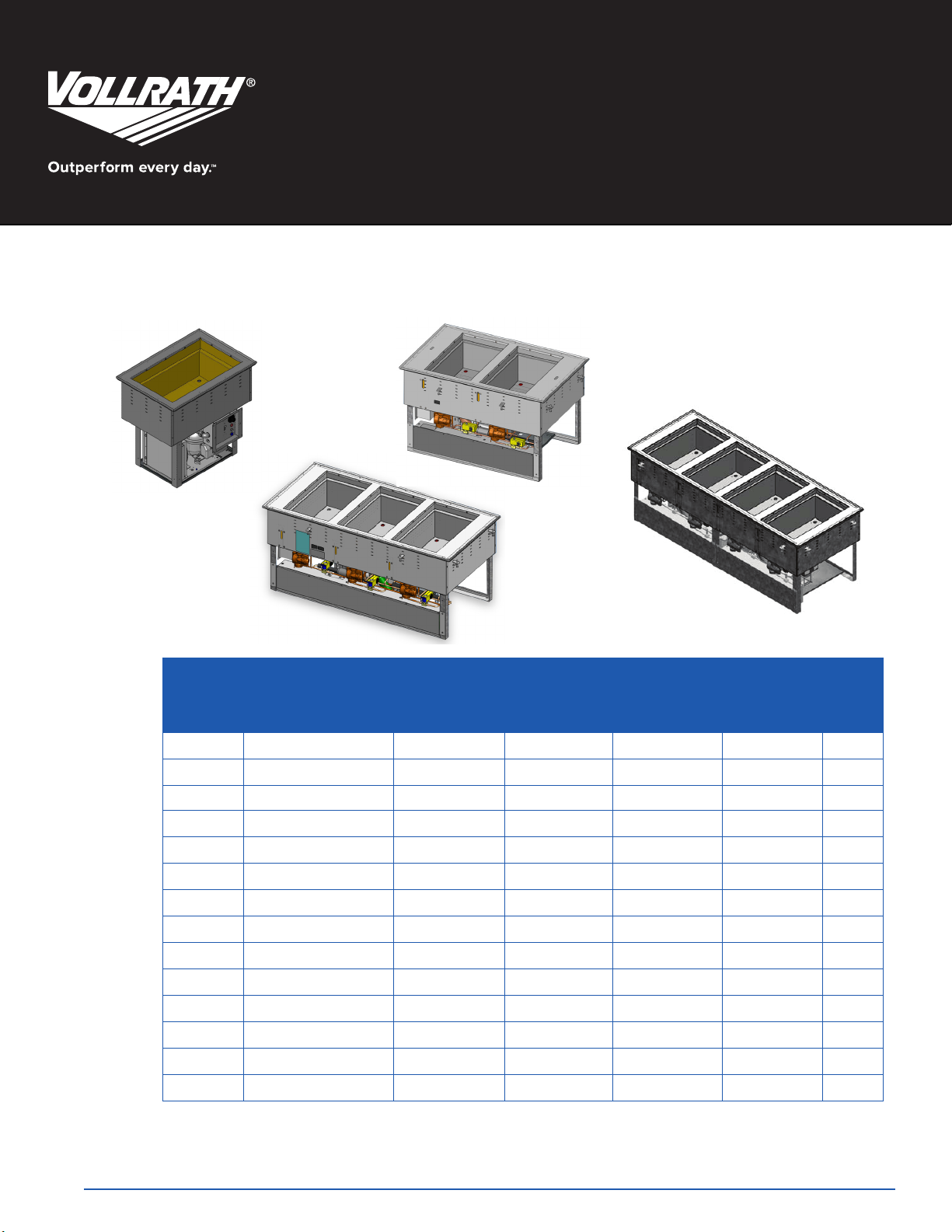
1 WELL, 2 WELL, 3 WELL, AND 4 WELL HOT/COLD DROP-IN
(NSF7 Cold Food Holding and NSF4 Hot Food Holding)
Heater
Item Description
3667101D 1 Well Hot/Cold Drop-in 625W 1/4 hp 6.0 120V 5-15P
3667102D 1 Well Hot/Cold Drop-in 625W 1/4 hp 6.0 120/208-240V 14-20P
3667101U 1 Well Hot/Cold Drop-in 625W 1/4 hp 6.0 120V 5-15P
3667102U 1 Well Hot/Cold Drop-in 625W 1/4 hp 6.0 120/208-240V 14-20P
3667201D 2 Well Hot/Cold Drop-in 625W 1/4 hp 11.2 120V 5-15P
3667202D 2 Well Hot/Cold Drop-in 625W 1/4 hp 8.6 120/208-240V 14-20P
3667201DA 2 Well Hot/Cold Drop-in 625W 1/4 hp 11.2 120V 5-15P
3667202DA 2 Well Hot/Cold Drop-in 625W 1/4 hp 8.6 120/208-240V 14-20P
3667301D 3 Well Hot/Cold Drop-in 625W 1/4 hp 16.0 120V 5-20P
3667302D 3 Well Hot/Cold Drop-in 625W 1/4 hp 11.2 120/208-240V 14-20P
3667301DA 3 Well Hot/Cold Drop-in 625W 1/4 hp 16.0 120V 5-20P
3667302DA 3 Well Hot/Cold Drop-in 625W 1/4 hp 11.2 120/208-240V 14-20P
3667402D 4 Well Hot/Cold Drop-in 625W (2) 1/4 hp 14.0 120/208-240V 14-20P
3667402DA 4 Well Hot/Cold Drop-in 625W (2) 1/4 hp 14.0 120/208-240V 14-20P
Watts
(per well)
HP (R404
Compressor)
Max Amps
Voltage Plug
Draw
Thank you for purchasing this Vollrath equipment. Before operating the equipment, read and familiarize yourself with the following operating
and safety instructions. SAVE THESE INSTRUCTIONS FOR FUTURE REFERENCE.
Item No. 2350245-1 Rev 6/14
Page 2
Safety PrecautionS
To ensure safe operation, read the following statements and understand
their meaning. Please read carefully.
3. Dispose all packaging materials in an environmentally responsible
manner.
inStallation
WARNING
Warning is used to indicate the presence of a hazard that can cause severe
personal injury, death, or substantial property damage if the warning is
ignored.
CAUTION
Caution is used to indicate the presence of a hazard that will or can cause
minor personal injury or property damage if the caution is ignored.
NOTE
Note is used to notify people of installation, operation, or maintenance
information that is important but not hazard-related.
For Your Safety!
These precautions should be followed at all times. Failure to follow these
precautions could result in injury to yourself and others.
To reduce risk of injury or damage to the equipment:
Use only grounded electrical outlets matching the nameplate rated
voltage.
Have the equipment installed by qualied personnel.
Do not use an extension cord with this equipment. Do not plug this
equipment into a power strip or multi-outlet power cord.
Unit should only be used in a at, level position.
Do not spray controls or outside of equipment with liquids or cleaning
ENGLISH
agents.
Do not clean the equipment with steel wool.
Keep equipment and power cord away from open ames, electric
burners or excessive heat.
Do not use food pans deeper than 6" (15.2 cm).
Do not operate equipment in public areas and/or around children.
Do not operate if equipment has been damaged or is malfunctioning in
any way.
Do not operate hot well without water.
This unit must be installed on a dedicated electrical circuit in accordance
with local codes. Installation must be qualied service personnel.
ClearanCe requirements
One, two and three well drop-ins are zero clearance on all sides.
Four well drop-in requires zero clearance on sides and 1 1/2”
clearance at the bottom.
Venting requirements
The Hot/Cold Drop-ins must have adequate ventilation. Minimum
requirements are listed in the table below.
Number of cutouts
Drop-in
One Well 1 1 8" x 10″
Two Well 1 1 8" x 10″
Three- Well 1 1 8″ x 10″
Four-Well 2 2 8″ x 10″
The preferred location for the venting cutouts is on the short ends of the
cabinet. If the short end are not available the long sides can be used. See
drawings below. When louvers are installed in the long sides, Vollrath
recommends using a fan to assist air movement.
Figure 1. One and two drop-in well louver cutout locations
Alternate
Alternate
SizeIntake Discharge
Alternate
PreferredPreferred
Alternate
2
function and PurPoSe
This unit is intended and designed to keep food at proper serving
temperatures. This unit is made for use in an ambient temperature below
86 °F (30 °C). Using in warmer temperatures will take unit out of NSF
Preferred
compliance. Modifying refrigeration parameters may void the warranty.
Hot food stations are not intended or designed to cook raw food or to reheat
prepared food. Cold food stations are not intended or designed to cool or
Figure 2. Three well drop-in louver cutout locations
chill food. Food must be prepared and placed in food stations at proper
serving temperatures. Refrigerated cold stations are best used for holding
periods up to four hours. For best performance, stainless steel containers
are recommended.
This equipment is not intended for household, industrial or laboratory use.
Preferred
unPacking the equiPment
1. Remove all packing material and tape, as well as any protective plastic
from the equipment.
2. Clean any glue residue left over from the plastic or tape.
OperatOr’s Manual
Figure 3. Four well drop-in louver cutout locations
Alternate
Preferred
Alternate
Preferred
Alternate
Page 3

Control Box mounting
1
0
9
8
7
6
5
4
3
2
1
0
1
0
9
8
7
6
5
4
3
2
1
0
1
0
9
8
7
6
5
4
3
2
1
0
Controls must be mounted on the operator side (raceway side) for proper
orientation with wells. The control box requires 3″ of depth in the cabinet
when using the included frame. Without the frame, the control box requires
4″ of depth in the cabinet.
Control Box Cutout Dimensions
seal tHe Flange
Top Mount
1. Place a bead of silicone sealer rated at a minimum of 450 °F (232 °C)
around the well ange to prevent water from leaking into control areas.
2. Set the clips into slots
3. Tighten the thumbscrews slowly and in an alternating pattern to evenly
Model Cutout Dimension
One Well Drop-in 7" x 8”
Two Well Drop-in 7" x 10-1/2"
Three Well Drop-in 7" x 13"
Four Well Drop-in 7" x 15-1/2"
compress the silicone.
Bottom Mount
Place a bead of silicone sealer rated at a minimum of 450 °F (232 °C)
between the countertop and the inside of the well to prevent water from
leaking into control areas, and in mounting holes when using rivets or other
fasteners.
Control Box loCations
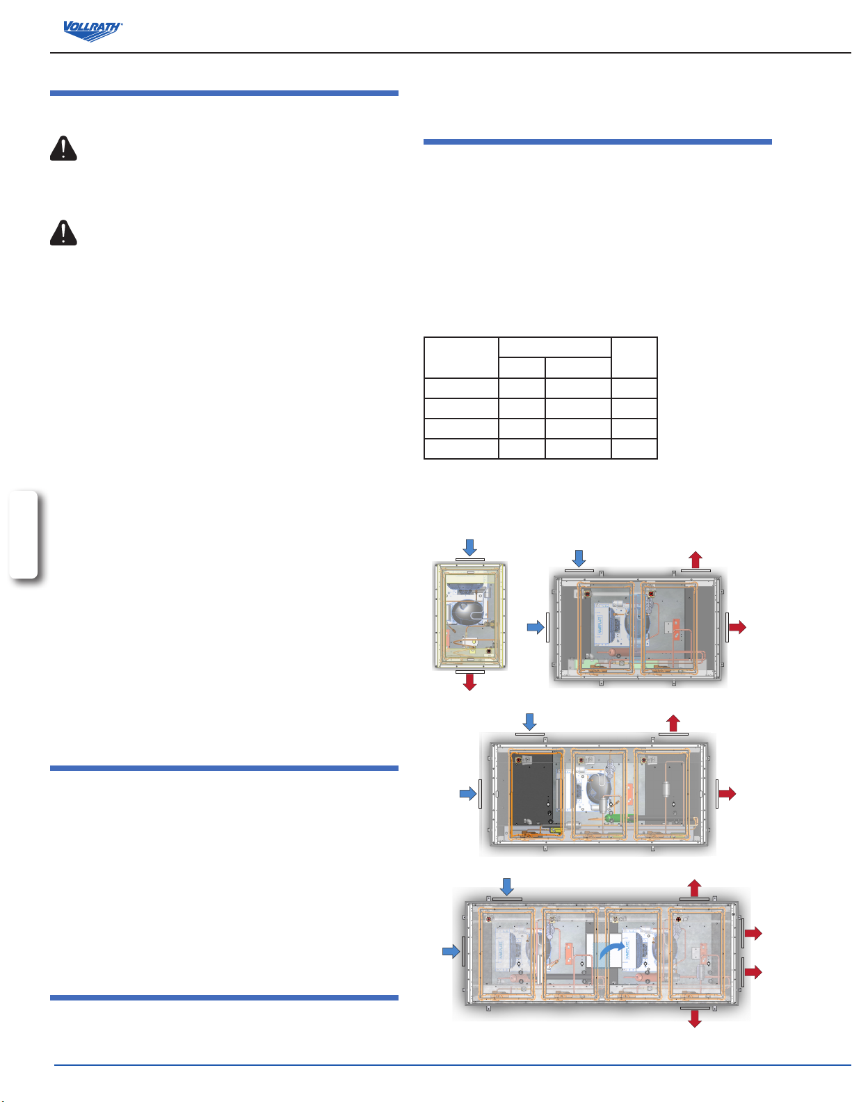
Control Box
Raceway
Figure 4. Two well drop-in control box mounting
Figure 5. Three well drop-in control box mounting
Control Box
Raceway
Control Box
Raceway
controlS
D
A
Figure 7. Controls.
A
ON/OFF SWITCH. Switches the equipment power “ON” or “OFF”.
B
MODE SELECTOR SWITCH. The down position selects refrigeration
mode. The up position selects heating mode The center position
selects neutral mode. When the switch is in the center or up positions,
the drain valve will be closed.
C
REFRIGERATION INDICATOR LIGHT. Illuminates when the unit is in
the refrigeration mode.
E
B
C
ENGLISH
Figure 6. Four well drop-in control box mounting
Hot/ColD Well Drop-in Cutout Dimensions
Model Cutout Dimension
One Well Top Mount Drop-in 25-1/4" x 17-5/16"
One Well Bottom Mount Drop-in
Two Well Drop-in 25-1/4" x 40-3/4"
Three Well Drop-in 25-1/4" x 54"
Four Well Drop-in 25-1/4" x 67-1/4"
NOTE: Well cutouts must have a corner radius of 7/8".
NOTE: Control cutouts must have a corner radius of 3/8".
Per customer specication for
amount of visible top ange
D
TEMPERATURE CONTROL DIAL (Hot Mode Only). Used to set
or adjust the hot temperature of the well. The higher the number
the higher the temperature, the lower the number the lower the
temperature.
E
HEATING INDICATOR LIGHT. Illuminates when the unit is in the
heating mode.
OperatOr’s Manual
3
Page 4

oPeration
NOTE: Before using this equipment it must be cleaned and dried
thoroughly.
WARNING
Burn Hazard.
Do not touch heating surfaces, liquid, or food while
unit is heating or operating.
Hot food, steam and liquids can burn skin. Allow the hot liquid,
spillage pans and trays to cool before handling. Use gloves, mitts or
pot holders if it is necessary to handle hot pans.
WARNING
Electrical Shock Hazard.
Keep water and other liquids from entering the
inside of the unit. Liquid inside the unit could cause
an electrical shock. Do not damaged power cord.
Do not over ll wells, pans or trays. Liquid could contact the
electrical components and cause a short circuit or an electrical
shock. Unplug unit before performing service, draining or removing
spillage pans and trays. Do not spray water or cleaning products.
Do not use a power cord that has been modied or damaged.
reFrigerateD moDe
NOTE: When switching from hot mode to refrigerated mode, turn the
mode selecting switch to the neutral mode center position.
Remove the hot food pans. Remove the drain plug or switch to
cold mode and drain water from the system. Drain the hot water
ENGLISH
before beginning refrigerated mode.
1. Plug the equipment into a properly grounded electrical supply matching
the nameplate rating. Damage to the equipment can occur if incorrect
power is supplied to equipment.
2. Turn the on/off switch (A) to the “ON” position.
3. Turn the mode selector switch (B) to the down position. This will open the
drain valve on models with auto-drains. On units with manual drain plugs,
remove the drain plug. Units do not have an adjustable temperature
setting.
4. Allow the unit to run for approximately 60 minutes.
NOTE: For the best performance when using ice with this unit, allow
unit to run for approximately 2 hours before adding ice. This
will help the ice remain solid.
5. Place containers of properly chilled food into the pre-chilled unit.
6. Regularly check the food temperature.
NOTE: Monitor food temperature closely for food safety. The United
States Public Health Service recommends that hot food be held
at a maximum of 41 ºF (5 ºC) to help prevent bacteria growth.
7. When nished using the unit, turn the mode selector switch (B) to the
middle position and turn the on/off (B) to the “OFF” position. Remove the
food containers.
Heating moDe
1. Plug the equipment into a properly grounded electrical supply
matching the nameplate rating. Damage to the equipment can occur
if incorrect power is supplied to equipment.
2. Turn the on/off switch (A) to the “ON” position. Turn the mode
selector switch (B) to the up position.
3. Fill the well to the correct level with clean fresh water. The correct
level is about 1” (2.5 cm) from the bottom. Always maintain water in
the well. Do not over ll. Allowing the well to run dry during operation
may reduce the service life of the equipment.
4. Preheat the water in the wells by covering wells with empty food
containers or covers. Turn the heat control (D) to the maximum heat
setting. Preheat for 60 minutes.
5. Place container of hot food product, above 140 °F (60 °C), into
preheated equipment.
6. Reduce heat setting to a level that will maintain a safe holding
temperature and maintain food quality. See food safety
precautionary note.
Food Safety Precautionary Note:
Monitor food temperature closely for food safety. The United States
Public Health Service recommends that hot food be held at a
minimum of 140 ºF (60 ºC) to help prevent bacteria growth. Maintain
correct water level and temperature setting. Periodically remove
food container and check the water level. Add water if needed.
During operation
1. Maintain water level. Periodically (approximately 2 hours) remove
container of food and check the water level. Add hot water if needed.
WHen FinisHeD using tHe equipment
1. Turn the mode selector switch (B) to the center position. Turn the on/
off switch (A) to the “OFF” position.
NOTE: When the selector switch (B) is in the center position or the
hot position the drain valve will be in the closed position.
2. When nished using the unit, remove the food containers.
3. When removing hot food containers from unit use gloves, mitts or
pot holders to protect hands.
4. Allow the unit and water to cool completely before cleaning.
4
OperatOr’s Manual
Page 5

cleaning
To maintain the appearance and increase the service life, clean your equipment daily.
NOTE: Do not use caustic cleaning chemicals, steel wool or commercial lime removal products to clean the equipment.
1. Remove the food containers.
2. If the drop-in was in heating mode, drain the water.
• If the unit has an automatic drain, turn the mode selector switch (B) to cold mode. This will allow the water to drain. Turn the ON/OFF switch to the “OFF”
position.
• If the unit has a manual drain, turn the ON/OFF switch to the “OFF”position. Let the water in the wells cool. Remove the drain plug to drain the water.
3. Let hot wells cool before cleaning.
4. Using a damp cloth, sponge dipped in soapy water to clean the inside of the well and the outside of the equipment.
5. Thoroughly rinse equipment with water after cleaning.
troubleShooting chart
Problem It might be caused by Course of Action
Unit is not plugged in. Plug unit in.
Unit does not have power.
Unit has power but is not operating. Unknown. Contact Vollrath Technical Services 800-632-0832.
Power switch is in the “OFF” position. Turn power switch to the “ON” position.
Circuit breaker is tripped. Reset the circuit breaker.
Defective circuit or in-adequate power supply. Call licensed electrician.
Service and rePair
There are no user serviceable parts within this appliance. To avoid serious injury or damage, never attempt to repair the equipment or replace a damaged
power cord yourself. Do not send equipment directly to the Vollrath Company. Please contact the qualied professional repair service listed below.
VOLLRATH Technical Service • 1-800-628-0832
www.vollrath.com
The Vollrath Company, L.L.C.
1236 North 18th Street
Sheboygan, WI 53081-3201
U.S.A.
Main Tel: 800.628.0830
Fax: 800.752.5620
Technical Services: 800.628.0832
Service Fax: 920.459.5462
Canada Service: 800.695.8560
© 2014 The Vollrath Company, L.L.C.
 Loading...