

Page 1

Model F231
OWNER’S MANUAL
Manual No. 513658 Rev.3
Page 2

Page 3

Owner’s Manual
For F231
Stoelting Floor Model Gravity Machine
This manual provides basic information about the machine. Instructions and suggestions are
given covering its operation and care.
The illustrations and specifi cations are not binding in detail. We reserve the right to make
changes to the machine without notice, and without incurring any obligation to modify or provide new parts for freezers built prior to date of change.
DO NOT ATTEMPT to operate the machine until instructions and safety precautions in this
manual are read completely and are thoroughly understood. If problems develop or questions
arise in connection with installation, operation, or servicing of the machine, contact the company at the following location:
STOELTING Ph: 800-558-5807
502 Hwy. 67
Kiel, WI 53042 Fax: 920-894-7029
© 2011 Stoelting, LLC, All Rights Reserved
Page 4

A Few Words About Safety
Safety Information
Read and understand the entire manual before
operating or maintaining Stoelting equipment.
This manual provides the operator with information
for the safe operation and maintenance of Stoelting
equipment. As with any machine, there are hazards
associated with their operation. For this reason safety
is emphasized throughout the manual. To highlight
specifi c safety information, the following safety defi ni-
tions are provided to assist the reader.
The purpose of safety symbols is to attract your attention to possible dangers. The safety symbols, and
their explanations, deserve your careful attention
and understanding. The safety warnings do not by
themselves eliminate any danger. The instructions
or warnings they give are not substitutes for proper
accident prevention measures.
If you need to replace a part, use genuine Stoelting
parts with the correct part number or an equivalent
part. We strongly recommend that you do not use
replacement parts of inferior quality.
Safety Alert Symbol:
This symbol Indicates danger, warning or caution.
Attention is required in order to avoid serious personal injury. The message that follows the symbol
contains important information about safety.
Signal Word:
Signal words are distinctive words used throughout
this manual that alert the reader to the existence and
relative degree of a hazard.
WARNING
The signal word “WARNING” indicates a potentially
hazardous situation, which, if not avoided, may result
in death or serious injury and equipment/property
damage.
CAUTION
The signal word “CAUTION” indicates a potentially
hazardous situation, which, if not avoided, may result
in minor or moderate injury and equipment/property
damage.
CAUTION
The signal word “CAUTION” not preceded by the
safety alert symbol indicates a potentially hazardous
situation, which, if not avoided, may result in equipment/property damage.
NOTICE
The signal word “NOTICE” indicates information or
procedures that relate directly or indirectly to the
safety or personnel or equipment/property.
Page 5

TABLE OF
CONTENTS
Section Description Page
1 Description and Specifi cations
1.1 Description ..................................................................................................1
1.2 Specifi cations .............................................................................................1
2 Installation Instructions
2.1 Safety Precautions .....................................................................................3
2.2 Shipment and Transit ..................................................................................3
2.3 Machine Installation ....................................................................................3
2.4 Installing Permanent Wiring ........................................................................3
3 Initial Set-Up and Operation
3.1 Operator’s Safety Precautions ...................................................................5
3.2 Operating Controls and Indicators ..............................................................5
3.3 Disassembly of Machine Parts ...................................................................6
3.4 Cleaning Disassembled Parts ....................................................................7
3.5 Sanitizing Machine Parts ............................................................................7
3.6 Cleaning the Machine .................................................................................7
3.7 Assembling Machine ..................................................................................8
3.8 Sanitizing ....................................................................................................8
3.9 Freeze Down and Operation ......................................................................9
3.10 Fine Consistency Adjustment .....................................................................9
3.11 Mix Information ...........................................................................................10
4 Maintenance and Adjustments
4.1 Drive Belt Tension Adjustment ....................................................................11
4.2 Condenser Cleaning (Air-Cooled Machines) ..............................................11
4.3 Preventative Maintenance ..........................................................................11
4.4 Extended Storage .......................................................................................12
5 Troubleshooting
5.1 Error Codes ................................................................................................13
5.2 Troubleshooting ..........................................................................................13
6 Replacement Parts
6.1 Decals and Lubrication ...............................................................................17
6.2 Auger Shaft and Faceplate Parts ...............................................................18
Page 6

Page 7
SECTION 1
INTRODUCTION
1.1 DESCRIPTION
The Stoelting F231 fl oor machine is gravity fed. The
machine is equipped with the IntelliTec2 control which
provides a uniform product. The F231 is designed to
operate with almost any type of commercial soft serve or
non-dairy mixes available, including: ice milk, ice cream,
yogurt, and frozen dietary desserts.
This manual is designed to assist qualifi ed service per-
sonnel and operators in the installation, operation and
maintenance of the Stoelting F231 gravity machine.
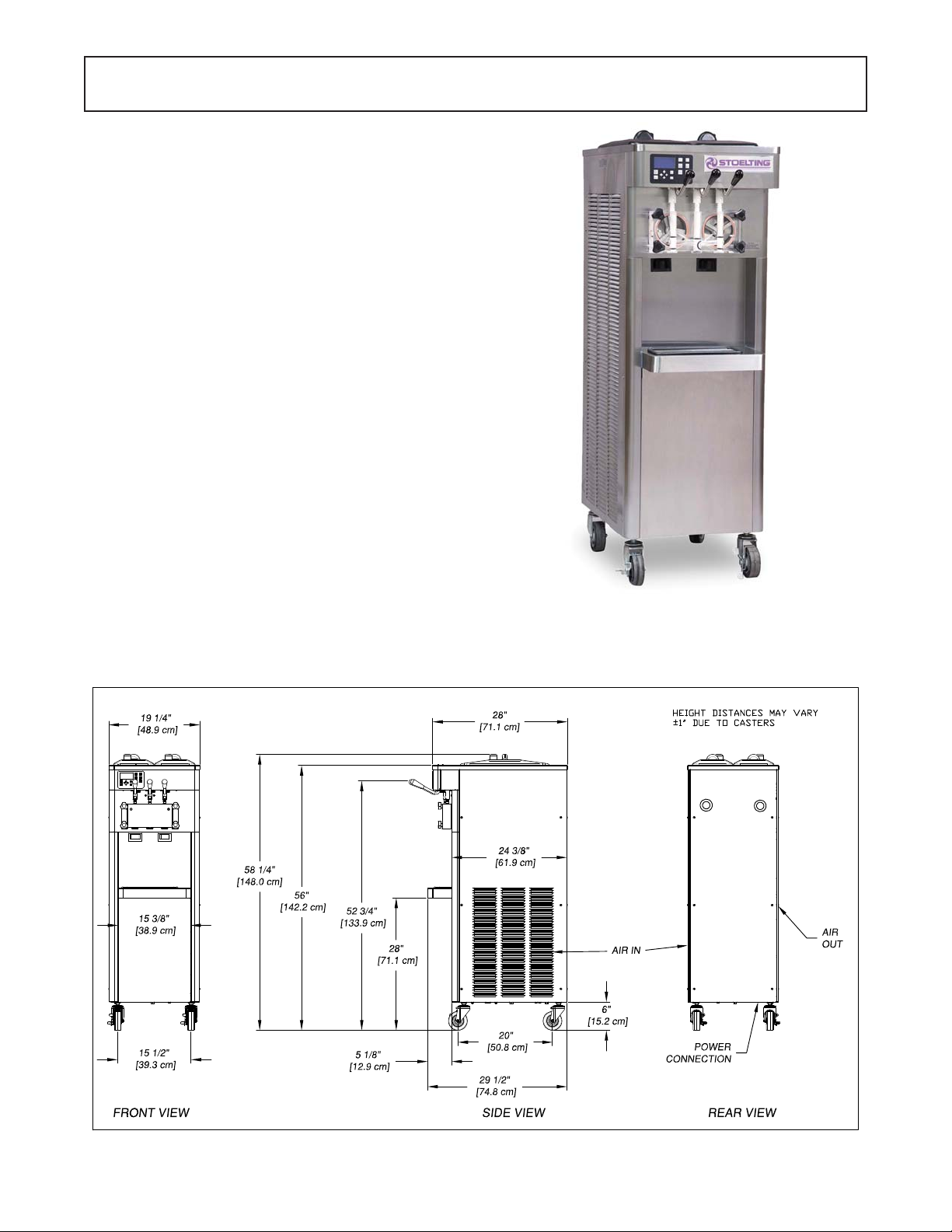
1.2 SPECIFICATIONS
Figure 1-1 Model F231
Figure 1-2 Specifi cation
1
Page 8
1.2 SPECIFICATIONS
Model F231
Dimensions Machine as shipped
width 19-1/4’’ (48,9 cm) 32’’ (81,3 cm)
height 58-1/4’’ (148,0 cm) 60’’ (152,4 cm)
depth 28’’ (71,1 cm) 39’’ (99,1 cm)
Weight 400 lbs (181,4 kg) 470 lbs (213,1 kg)
Electrical 1 Phase, 208-240 VAC, 60Hz 3 Phase, 208-240 VAC, 60Hz
running amps 12A 10A
connection type NEMA 6-20P power cord provided NEMA L15-20P power cord provided
International Option 1 Phase, 220-240 VAC, 50Hz
Compressor 12,000 Btu/hr (R-404A)
Drive Motor Two - 3/4 hp
Air Flow Air cooled units require 3” (7,6 cm) air space on both sides
Water cooled units require 1/2” N.P.T. water and drain fi ttings.
Plumbing Fittings
Maximum water pressure of 130 psi. Minimum water fl ow rate of 3 GPM. Ideal
EWT of 50°-70°F
Hopper Volume Two - 3 gallon (11,35 liters)
Freezing Cylinder
Volume
Two - 0.85 gallon (3,22 liters)
2
Page 9
SECTION 2
INSTALLATION INSTRUCTIONS
2.1 SAFETY PRECAUTIONS
Do not attempt to operate the machine until the safety
precautions and operating instructions in this manual are
read completely and are thoroughly understood.
Take notice of all warning labels on the machine. The labels have been put there to help maintain a safe working
environment. The labels have been designed to withstand
washing and cleaning. All labels must remain legible for
the life of the machine. Labels should be checked periodically to be sure they can be recognized as warning labels.
If danger, warning or caution labels are needed, indicate
the part number, type of label, location of label, and quantity
required along with your address and mail to:
STOELTING
ATTENTION: Customer Service
502 Hwy. 67
Kiel, Wisconsin 53042
2.2 SHIPMENT AND TRANSIT
The machine has been assembled, operated and inspected
at the factory. Upon arrival at the fi nal destination, the
entire machine must be checked for any damage which
may have occurred during transit.
With the method of packaging used, the machine should
arrive in excellent condition. THE CARRIER IS RESPONSIBLE FOR ALL DAMAGE IN TRANSIT, WHETHER
VISIBLE OR CONCEALED. Do not pay the freight bill
until the machine has been checked for damage. Have
the carrier note any visible damage on the freight bill. If
concealed damage and/or shortage is found later, advise
the carrier within 10 days and request inspection. The
customer must place claim for damages and/or shortages
in shipment with the carrier. Stoelting, Inc. cannot make
any claims against the carrier.
C. The machine must be placed in a solid level
position.
NOTE
Accurate leveling is necessary for correct drainage
of freezing cylinder and to insure correct overrun.
D. Machines with air cooled condensers require a
minimum of 3” (7,5cm) of space on both sides
for proper circulation.
E. On air cooled machines, install the air baffl e to
the bottom of the right side panel. Remove the
panel screws and put the baffl e in place. Align
the bottom of the baffl e with the fl oor and tighten
the panel screws (Fig. 2-1).
E. Machines that have a water cooled condenser
require 1/2” NPT supply and drain fi ttings.
2.3 MACHINE INSTALLATION
WARNING
Installation must be completed by a qualifi ed
electrician/refrigeration specialist.
Incorrect installation may cause personal injury,
severe damage to the machine and will void factory warranty.
Installation of the machine involves moving the machine
close to its permanent location, removing all crating, setting in place, assembling parts, and cleaning.
A. Uncrate the machine.
B. Install the four casters. Turn the threaded end
into the machine until no threads are showing. T o
level, turn out casters no more than 1/4” maximum,
then tighten all jam nuts.
Figure 2-1 Installing Baffl e
2.4 INSTALLING PERMANENT WIRING
To install wiring follow the steps below:
A. Refer to the nameplate on the side panel of the
machine for specifi c electrical requirements. Make
sure the power source in the building matches
the nameplate requirements.
B. Remove the back panel and the junction box
cover located at the bottom of the machine.
C. Install permanent wiring according to local code.
3
Page 10

4
Page 11

SECTION 3
INITIAL SET-UP AND OPERATION
3.1 OPERATOR’S SAFETY PRECAUTIONS
SAFE OPERATION IS NO ACCIDENT; observe these
rules:
A. Know the machine. Read and understand the
Operating Instructions.
B. Notice all warning labels on the machine.
C. Wear proper clothing. Avoid loose fi tting garments,
and remove watches, rings or jewelry that could
cause a serious accident.
D. Maintain a clean work area. Avoid accidents by
cleaning up the area and keeping it clean.
E. Stay alert at all times. Know which switch, push
button or control you are about to use and what
effect it is going to have.
F. Disconnect power for maintenance. Never
attempt to repair or perform maintenance on the
machine until the main electrical power has been
disconnected.
G. Do not operate under unsafe operating conditions.
Never operate the machine if unusual or excessive
noise or vibration occurs.
3.2 OPERATING CONTROLS AND INDICATORS
Before operating the machine, it is required that the operator know the function of each operating control. Refer
to Figure 3-1 for the location of the operating controls on
the machine. For the information regarding error codes
displayed on the control panel, refer to the troubleshooting
section of this manual.
A. INTELLITEC2 TOUCHPAD
WARNING
High voltage will shock, burn or cause death. The
OFF-ON switch must be placed in the OFF position
prior to disassembling for cleaning or servicing. Do
not operate machine with panels removed.
Main Power On/Off
The Main Power button is used to supply power to the
IntelliTec2 control, the freezing cylinder circuits and the
storage refrigeration system. When the machine is fi rst
plugged in, the control defaults to the On status with power
to the hopper only. If the Main Power On/Off button is
pressed when the machine is on, the machine will turn
off and a status message will be displayed on the screen.
IntelliT ec2 Control
(See Figure 3-2)
Figure 3-1 Machine Controls
Dispense
Rate Adjustor
5
Page 12

Figure 3-2 IntelliTec2 Control
Help
Pressing the Help button will display help information
dependant on the cursor’s location. Pressing the Help
button again will exit the help screen.
Selection Button (SEL)
The SEL button is used by technicians to select menu
options.
Set Button (SET)
The SET button is used by technicians to save changes
when modifying control settings.
On/Off Button
Power to the freezing cylinders can then be controlled
with the On/Off Left and On/Off Right switches.
Push to Freeze Button
Pressing the PUSH TO FREEZE button initiates “Serve
Mode”.
Clean Button
The CLEAN button initiates “Clean Mode”.
Arrow Buttons ()
The arrow buttons are used by technicians to navigate
through the control readings and settings.
B. SPIGOT SWITCH
The spigot switch is mounted to the spigot cam assembly
behind the header panel. When the spigot is opened to
dispense product, the spigot switch opens and the “Serve
Mode” begins.
C. DISPENSE RATE ADJUSTOR
The dispense rate adjustor is located under the header
panel, to the immediate right of the spigot handles. Turning
the knob counterclockwise will decrease the dispense rate.
D. MIX LOW LIGHTS
The mix low lights are located at the back of the F231.
There is a light for each freezing cylinder. A steady light
signifi es a low mix condition. A blinking light signifi es an
error. The light will automatically turn off when the condition has been resolved.
E. USB ACCESS PORT
The USB access port is located on the right side panel
of the machine. The port is used by technicians to import
fi rmware and export machine statistics.
3.3 DISASSEMBLY OF MACHINE PARTS
Before using the machine for the fi rst time, complete
machine disassembly, cleaning and sanitizing procedures need to be followed. Routine cleaning intervals
and procedures must comply with the local and state
health codes. Inspection for worn or broken parts should
be made at every disassembly of the machine. All worn
or broken parts should be replaced to ensure safety to
both the operator and the customer and to maintain good
machine performance and a quality product. Check the
wear line on the auger fl ights on a regular basis (Fig.
3-3) and replace as needed. Frequency of cleaning must
comply with the local health regulations.
Wear Line
Figure 3-3 Auger Flight Wear
T o disassemble the machine, refer to the following steps:
A. REMOVING MIX
For the fi rst time cleaning the machine, skip to part B.
Disassembly of Front Door.
1. Press the Clean button. After mix has melted
(about 5 minutes) open the spigot to drain the
mix.
2 Fill the hopper with 2 gallons (8 liters) of cool tap
water.
3. Press the Clean button to run the machine. After
30 seconds press the Clean button again to stop
the auger.
4. Drain the water out of the machine.
NOTE
If the water does not drain clear, repeat steps 2-4.
5. Use Stera-Sheen or equivalent sanitizing solution
mixed according to manufacturer’s instructions to
provide a 100 parts per million strength solution.
Mix sanitizer in quantities of no less than 2
gallons of 90° to 1 10°F (32°C to 43°C) water. Any
sanitizer must be used only in accordance with
the manufacturer’s instructions.
6. Pour the sanitizer into the hopper.
7. Using brushes provided, scrub the hopper.
8. After 5 minutes, drain the sanitizer out of the
freezing cylinder.
6
Page 13

B. DISASSEMBLY OF FRONT DOOR
1. Turn the machine off by pressing the Main Freezer
Power Off/On button on the IntelliTec2 control.
2. Remove the knobs on the front door.
3. Remove the front door by pulling it off the studs.
4. Remove the spigot through the bottom of the front
door.
5. Remove all o-rings from parts by fi rst wiping off
the lubrication using a clean towel. Then squeeze
the o-ring upward to form a loop (Fig. 3-4). Roll
the o-ring out of the groove.
Figure 3-4 Removing O-Ring
B. DISASSEMBLY OF AUGER
1. Remove the front auger support and bushing.
2. Remove the auger assembly from the machine.
Pull the auger out of the machine barrel slowly.
As the auger is being pulled out, carefully remove
each of the plastic fl ights with springs.
3. Keep the rear of the auger tipped up once it is
clear of the freezing cylinder to prevent the rear
seal assembly from dropping.
4. Wipe the spline lubricant off of the hex end of the
auger with a paper towel. Remove the rear seal
assembly (Fig. 3-5).
5. Unscrew the springs from the auger fl ights.
3.4 CLEANING DISASSEMBLED PARTS
Disassembled machine parts require complete cleaning,
sanitizing and air drying before assembling. Local and state
health codes will dictate the procedure required. Some
state health codes require a four sink process (pre-wash,
wash, rinse, sanitize, air dry), while others require a three
sink process (without the pre-wash step). The following
procedures are a general guideline only. Consult your
local and state health codes for the procedures required
in your location.
A. Prepare Stera-Sheen or equivalent cleaner in
2 gallons of 90° to 110°F (32° to 43°C) water
following manufacturers instructions. Place all
parts in the solution and clean with provided
brushes.
B. Rinse all parts with clean 90° to 110°F (32° to
43°C) water.
C. Wash the hopper and freezing cylinder with the
Stera-Sheen solution and brushes provided.
D. Clean the rear seal surfaces from the inside of the
freezing cylinder with the Stera-Sheen Solution.
3.5 SANITIZING MACHINE PARTS
A. Use Stera-Sheen or equivalent sanitizing solution
mixed according to manufacturer’s instructions to
provide a 100 parts per million strength solution.
Mix sanitizer in quantities of no less than 2
gallons of 90° to 1 10°F (32°C to 43°C) water. Any
sanitizer must be used only in accordance with
the manufacturer’s instructions.
B. Place all parts in the sanitizing solution for 5
minutes, then remove and let air dry completely
before assembling in machine.
3.6 CLEANING THE MACHINE
The exterior should be kept clean at all times to preserve
the luster of the stainless steel. A high grade of stainless
steel has been used on the machine to ease cleanup. To
remove spilled or dried mix, wash the exterior with 90° to
1 10°F (32°C to 43°C) Stera-Sheen solution or equivalent
cleaner and wipe dry.
Do not use highly abrasive materials, as they will mar the
fi nish. Use a soft cloth or sponge to apply the solution.
For best results, wipe with the grain of the steel.
A. Clean the rear seal surface from inside of the
freezing cylinder.
Figure 3-5 Rear Seal Assembly
7
Page 14

B. Using sanitizing solution and the large barrel
brush provided, sanitize the freezing cylinder by
dipping the brush in the sanitizing solution and
brushing the inside of the freezing cylinder.
NOTE
Do not let sanitizing solution sit overnight in the
freezing cylinder.
C. Remove the drip tray by pulling from the front
panel. Clean and replace the drip tray.
3.7 ASSEMBLING MACHINE
T o assemble the machine parts, refer to the following steps:
NOTICE
Petrol-Gel sanitary lubricant or equivalent must be
used when lubrication of machine parts is specifi ed.
NOTICE
The United States Department of Agriculture and
the Food and Drug Administration require that lubricants used on food processing equipment be certifi ed for this use. Use lubricants only in accordance
with the manufacturer’s instructions.
A. Assemble all o-rings onto parts dry, without
lubrication. Then apply a thin fi lm of sanitary
lubricant to exposed surfaces of the o-rings.
B. Lubricate the rear seal area on the auger shaft
with a thin layer of sanitary lubricant. Install the
rear seal o-ring. Lubricate the outside of the rear
seal o-ring with sanitary lubricant.
C. Lubricate the inside metal surface of the rear
seal and install it onto the auger shaft. DO NOT
lubricate the outside of the rear auger seal (Fig.
3-6).
D. Lubricate the hex drive end of the auger with a
small amount of spline lubricant. A small container
of spline lubricant is shipped with the machine.
E. Screw the springs onto the studs in the plastic
fl ights. The springs must be screwed into the
fl ights completely to provide proper compression.
F. Install the two plastic fl ights onto the rear of the
auger and insert it part way into the freezing
cylinder.
G. Install the remaining plastic fl ights, push the auger
into the freezing cylinder and rotate slowly until
the auger engages the drive shaft.
H. Apply a thin layer of sanitary lubricant to the inside
and outside of the auger support bushing. Install
the bushing onto the auger support and install the
auger support into the front of the auger. Rotate
the auger support so that one leg of the support
points straight up.
I. Apply a thin layer of sanitary lubricant to the
o-rings on the spigot body and install the spigot
body through the bottom of the front door.
K. Apply a thin fi lm of sanitary lubricant to the door
seal o-ring and fi t it into the groove on the rear
of the front door.
M. Place the front door assembly on the mounting
studs and the push front door against the machine
carefully.
N. Secure the front door to the machine by placing
the knobs on the studs and tightening until fi nger
tight. Do not overtighten. A proper o-ring seal can
be observed through the transparent front door.
3.8 SANITIZING
Sanitizing must be done after the machine is clean and
just before the machine is fi lled with mix. Sanitizing the
night before is not effective. However , you should always
clean the machine and parts after using it.
NOTE
The United States Department of Agriculture and
the Food and Drug Administration require that all
cleaning and sanitizing solutions used with food
processing equipment be certifi ed for this use.
Figure 3-6 Lubricate Rear Seal
When sanitizing the machine, refer to local sanitary regulations for applicable codes and recommended sanitizing
products and procedures. The frequency of sanitizing
must comply with local health regulations. Mix sanitizer
according to manufacturer’s instructions to provide a 100
parts per million strength solution. Mix sanitizer in quantities of no less than 2 gallons of 90°F to 110°F (32°C to
43°C) water. Allow sanitizer to contact the surfaces to be
sanitized for 5 minutes. Any sanitizer must be used only
in accordance with the manufacturer’s instructions.
8
Page 15

A. Prepare 2 gallons of Stera-Sheen sanitizing
solution following the manufacturer’s instructions.
B. Install the mix inlet regulator into the hopper.
C. Pour the sanitizing solution into the hopper.
D. Make sure the display shows the freezing cylinder
is off. If it is not, press the On/Off Left or On/Off
Right button to turn it off.
NOTE
If the freezing cylinder is not off, the control will
not go into Clean mode. This is to protect from accidentally going into Clean mode.
E. Press the CLEAN button.
F. Check for leaks.
1. Check for leaks at the front door seals.
2. Check the drain tray located under the front
door for leaks coming from the rear of the rear
auger seal.
G. Using a sanitized soft bristle brush (or equivalent)
dipped in sanitizing solution, clean the hopper
sides, mix inlet regulator and underside of the
hopper cover.
H. After fi ve minutes, open the spigot to expel
sanitizing solution. Drain all of the solution from
the machine.
I. When the solution has drained, press the CLEAN
button to stop the auger. Allow the freezing cylinder
to drain completely.
The machine is now sanitized and ready for adding mix.
3.9 FREEZE DOWN AND OPERATION
A. Sanitize immediately before use.
B. Make sure the display shows the freezing cylinder
is off. If it is not, press the On/Off Left or On/Off
Right button to turn it off.
C. Fill the hopper with at least 2.5 gallons of mix.
D. Place a container under the spigot and open the
spigot to allow the mix to fl ush out about 8 ounces
(0.23 liters) of sanitizing solution and liquid mix.
E. Press the On/Off button for the cylinder.
F. Press the PUSH TO FREEZE button.
NOTE
After the drive motor starts, there is a 3-second
delay before the compressor starts.
G. When the product is at 75% consistency, the
display will read “SERVE”. Open the spigot to
dispense product.
H. The machine dispenses product at a reasonable
draw rate. If the machine is overdrawn, the result
is a soft product or a product that will not dispense
at all. If this occurs, allow the machine to run for
approximately 30 seconds before dispensing more
product. A dispense rate adjustor is located under
the header panel, to the immediate right of the
spigot handle. Turning the knob counterclockwise
will decrease the dispense rate.
I. Do not operate the machine when the MIX LOW
message is displayed. Refi ll the mix container
immediately.
NOTE
The control has a standby mode for Serve 1 and
a sleep mode for Serve 1 and Serve 2. After a
preset number of freezing cycles in Serve 1, it will
enter the standby mode (followed by sleep mode)
and remain there until someone draws product or
presses the PUSH TO FREEZE button. In Serve 2
the control directly goes into the Sleep 2 mode. In
the sleep mode, the machine will keep the product
below 41°F (5°C). Sleep modes do not take the
place of cleaning and sanitizing. Federal, State,
and local regulatory agencies determine frequency
of cleaning and sanitizing.
3.10 FINE CONSISTENCY ADJUSTMENT
If the product consistency needs to be adjusted, use the
Fine Consistency Adjustment. To access the setting, the
Associate level password must be entered. Follow the
steps below for the Fine Consistency Adjustment.
A. Press the left arrow from the Current Status
screen.
B. Press the right arrow then the SEL button from
the Password screen. After the password is
accepted, move the cursor to the Fine Consistency
Adjustment option and press the SEL button.
C. On the Fine Consistency Adjustment screen, press
the SEL button and use the arrows to modify the
setting. Adjust the Fine Consistency higher to
increase the consistency or lower to decrease
the consistency.
D. Press the SET button to save the changes. Make
adjustments in increments of 5 for best results.
9
Page 16

3.11 MIX INFORMATION
Mix can vary considerably from one manufacturer to
another. Differences in the amount of butterfat content
and quantity and quality of other ingredients have a
direct bearing on the fi nished frozen product. A change
in machine performance that cannot be explained by a
technical problem may be related to the mix.
Proper product serving temperature varies from one
manufacturer’s mix to another. Mixes should provide a
satisfactory product in the 20°F to 24°F range. Diet and
low-carb mixes typically freeze to proper consistency at
higher temperatures.
When checking the temperature, stir the thermometer in
the frozen product to get an accurate reading.
Old mix, or mix that has been stored at too high a temperature, can result in a fi nished product that is unsatisfactory.
To retard bacteria growth in dairy based mixes, the best
storage temperature range is between 33° to 38°F (0.5°
to 3.3° C).
10
Page 17

SECTION 4
MAINTENANCE AND ADJUSTMENTS
This section is intended to provide maintenance personnel
with a general understanding of the machine adjustments.
It is recommended that any adjustments be made by a
qualifi ed person.
4.1 DRIVE BELT TENSION ADJUSTMENT
To check belt tension, refer to Figure 4-1 and follow the
steps below:
WARNING
Hazardous voltage
Make sure the machine is off when disassembling
for servicing. The machine must be disconnected
from electrical supply before removing any access
panel. Failure to disconnect power before servicing
could result in death or serious injury.
A. Remove the back panel.
B. Use a Burroughs Belt Tension Gauge to set the
tension for the drive belt. Set the belt tension to
35-40 lbs.
C. If an adjustment is necessary, loosen the four
motor plate retaining nuts, adjust belt tension
then retighten the four nuts.
D. Using a straightedge, check that the drive motor
pulley is aligned with the speed reducer pulley.
Align the pulley if necessary.
NOTE
Belt life will be increased if new drive belts are
tightened after two or three weeks of operation.
Figure 4-1 Belt Tension Adjustment
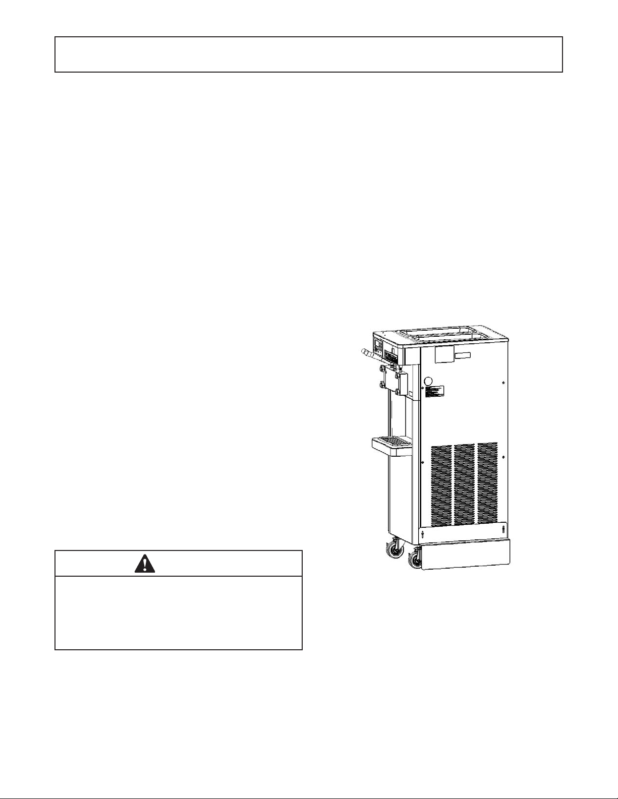
4.2 CONDENSER CLEANING (AIR-COOLED
MACHINES)
The F231 has an air-cooled or water-cooled condenser.
The air-cooled condenser is a copper tube and aluminum
fi n type. Condensing is totally dependent upon airfl ow. A
plugged condenser, or restrictions in the louvered panel will
restrict airfl ow. This will lower the capacity of the system
and damage the compressor. The condenser must be
kept clean of dirt and grease. The machine must have a
minimum of 3” (7.6 cm) of ventilation on the sides of the
unit for free fl ow of air. Make sure the machine is not pulling
over 100° F (37° C) air from other equipment in the area.
The water-cooled condenser is a tube and shell type. The
condenser needs a cool, clean supply of water to properly
cool the machine, inlet and discharge lines must be 3/8”
I.D. minimum.
The air-cooled condenser requires periodic cleaning. To
clean, refer to the following procedures.
A. Visually inspect the condenser for dirt.
B. If the condenser is dirty, place a wet towel over
the condenser.
C. Using compressed air or CO2 tank, blow out the
dirt from the back of the condenser. Most of the
dirt will cling to the wet towel.
D. An alternative method is to clean with a condenser
brush and vacuum.
NOTE
If the condenser is not kept clean, refrigeration effi ciency will be lost.
4.3 PREVENTATIVE MAINTENANCE
It is recommended that a preventative maintenance
schedule be followed to keep the machine clean and
operating properly . The following steps are suggested as
a preventative maintenance guide.
The United States department of agriculture and the food
and drug administration require that lubricants used in
food zones be certifi ed for this use. Use lubricants only
in accordance with the manufacturer’s instructions.
A. Daily checks
Check for any unusual noise or condition and
repair immediately.
B. Monthly checks
Check the condenser for dirt and clean if
necessary.
C. Quarterly Checks
Check drive belts for wear and tighten belts if
necessary.
11
Page 18

4.4 EXTENDED STORAGE
Refer to the following steps for storage of the machine
over any long period of shutdown time:
A. Clean all the parts that come in contact with mix
thoroughly with a warm detergent water. Rinse
in clear water and dry all parts. Do not sanitize.
NOTE
Do not let cleaning solution stand in the freezing
cylinder or hopper during the shutdown period.
B. Remove, disassemble, and clean the front door,
and auger shaft. Leave disassembled during the
shutdown period.
C. Place the auger fl ights and auger support bushing
in a plastic bag with a moist paper towel. This will
prevent them from becoming brittle if exposed to
dry air over an extended period of time (over 30
days).
D. For water-cooled machines that are left in unheated
buildings, or buildings subject to freezing, the water
must be shut off and disconnected. Disconnect
the water inlet fi tting. The fi tting is located at the
rear of the machine. Run the compressor for 2 - 3
minutes to open water valve (the front door must
be attached for the compressor to run). Blow
out all water through water inlet. Drain the water
supply line coming to the machine. Disconnect
the water outlet fi tting.
E. Press the Main Power On/Off button to turn the
machine off.
F. Disconnect the machine from the source of
electrical supply.
12
Page 19

SECTION 5
TROUBLESHOOTING
5.1 ERROR CODES
When the machine experiences a problem, one of the
following error codes will be displayed on the control
panel. Each error code directs you to the system location
of the malfunction.
ERROR CODE MALFUNCTION
2 High Torque
3 Run Time
4 Clean
5 Freezing Cylinder Sensor
6 Hopper Sensor (single hopper machines)
7 Drive Motor
8 Cab Sensor
9 High Pressure Cutout
10 Auxiliary Sensor
11 Prime (cab units only)
12 Left Hopper Sensor
13 Right Hopper Sensor
21 Spigot Open Time
To return the machine to normal operation, any error
causing condition must be corrected and the power to
the affected freezing cylinder must be cycled. Turn the
power to the freezing cylinder off then back on using the
On/Off button of the affected freezing cylinder.
5.2 TROUBLESHOOTING
Error Code 2 - High Torque
If the control panel displays a High Torque Error
(E2), the controller has sensed that the drive motor
is running at a high load for 10 or more seconds.
This may be due to the product consistency
adjustment being set too high. Press the On/Off
button for the cylinder to turn it off, wait until the
product in the freezing cylinder thaws and then
turn the cylinder back on. If the error persists,
contact your Authorized Stoelting Distributor for
further assistance.
Error Code 3 - Run Time
The Run Time Error (E3) occurs when the
compressor runs continuously for an extended
period. This error is generally caused by very
low mix levels in the hopper or from product
breakdown. Another common cause results from
a restriction preventing mix from entering the
freezing cylinder. Check the mix in the hopper.
If the level mix is low, add mix. If there is a
possibility that the mix has broken down, clean
and sanitize the machine and replace the mix
with fresh product.
Ice crystals in the hopper can clog the mix inlet
system and prevent mix from entering the freezing
cylinder. Thoroughly thaw mix per manufacturer’s
recommendations. T o check for ice crystals, pour
a small amount of product from the mix container
through a clean and sanitized sieve or strainer.
If ice crystals are in the mix, check temperature
of the walk-in cooler where the mix is stored.
In air cooled machines, the Run Time Error
may indicate that airfl ow within the machine
has reduced or stopped. Check the sides of the
machine for anything that would restrict airfl ow.
If the error persists after attempting to clear it,
contact your Authorized Stoelting Distributor for
further assistance.
Error Code 4 - Clean
If the machine is left in the Clean Mode for more
than 20 minutes, the control panel will display a
Clean Error (E4). This condition does not refl ect a
problem with the machine itself. The Clean Error
has been programmed into the controller as a
safeguard to protect the machine from potential
damage caused by the machine being accidentally
left in "Clean Mode". To clear the Clean Error,
press the On/Off button for the cylinder to turn if
off then back on.
13
Page 20

Error Code 5 - Freezing Cylinder Sensor
The Freezing Cylinder Sensor Error (E5) indicates
a failure of the barrel sensor or if the sensor is
out of range. If the control panel displays an E5,
press the On/Off button for the cylinder to turn
if off then back on. If the error persists, contact
your Authorized Stoelting Distributor for further
assistance.
NOTE
When the machine encounters a Freezing Cylinder
Sensor Error, the machine will continue to run using
preset timers. This mode will allow the operator to
continue serving product until the machine can be
serviced.
Error Code 6 - Hopper Sensor (single hopper machines)
The Hopper Sensor Error (E6) will not occur on
the machine.
Error Code 7 - Drive Motor
If the control panel displays a Drive Motor Error
(E7), the control does not sense current coming
from the drive motor. Press the On/Off button
for the cylinder to turn if off then back on. If the
error persists, contact your Authorized Stoelting
Distributor for further assistance.
Error Code 8 - Cab Sensor
A Cab Sensor Error (E8) will not occur on the
machine.
Error Code 9 - High Pressure Cutout
High Pressure Cutout Errors (E9) are usually
caused by a dirty or ineffi cient condenser. If the
control panel displays an E9 on an air cooled
machine, check for proper air clearance around
the machine. If there is an E9 on a water cooled
machine check for proper fl ow from the water
supply or kinks in the hoses.
If the error persists, contact your Authorized
Stoelting Distributor for further assistance.
Error Code 10 - Auxiliary Sensor
An Auxiliary Temperature Sensor Error (E10)
occurs if the temperature sensor on the control
board fails. Press the On/Off button for the cylinder
to turn if off then back on. If the error persists,
contact your Authorized Stoelting Distributor for
further assistance
Error Code 11 - Prime Error
The Prime Error (E11) will not occur on the
machine.
Error Code 12 - Left Hopper Sensor
The Left Hopper Sensor Error (E12) indicates
a failure of the hopper sensor or if the sensor is
out of range. If the control panel displays an E12,
press the On/Off button for the cylinder to turn
if off then back on. If the error persists, contact
your Authorized Stoelting Distributor for further
assistance.
Error Code 13 - Right Hopper Sensor
The Right Hopper Sensor Error (E13) indicates
a failure of the hopper sensor or if the sensor is
out of range. If the control panel displays an E12,
press the On/Off button for the cylinder to turn
if off then back on. If the error persists, contact
your Authorized Stoelting Distributor for further
assistance.
Error Code 21 - Spigot Open Time
The Spigot Open Time Error (E21) indicates a
failure of the spigot switch. If the control senses
the spigot is open continuously for 10 minutes, the
machine will go into Sleep 3 mode. If the control
panel displays an E21, press the On/Off button
for the cylinder to turn if off then back on. If the
error persists, contact your Authorized Stoelting
Distributor for further assistance.
14
Page 21

5.3 TROUBLESHOOTING - MACHINE
PROBLEM POSSIBLE CAUSE REMEDY
1 Power to machine is off. 1 Supply power to machine.
Machine does not
run.
Machine will not
shut off.
Product is too fi rm.
2 Freeze-up (auger will not turn). 2 Turn Clean/Off/On switch Off for 15 minutes,
then restart.
3 Front door not in place. 3 Assemble front door in place.
1 Drive belt failure. 1 Replace drive belt.
2 Consistency temperature setting is too
fi rm.
3 Refrigeration problem. 3 Check system. (Call distributor for service)
1 CutOut Consistency setting too high 1 Adjust the CutOut Consistency (See Section 3)
2 Turn Consistency Adjustment knob counter-
clockwise.
Product is too soft.
Product does not
dispense.
Drive belt slipping
or squealing.
Rear auger seal
leaks.
Front door leaks.
1 No vent space for free fl ow of cooling
air.
2 Condenser is dirty. 2 Clean the condenser. (See Section 3)
3 CutOut Consistency setting too low 3 Adjust the CutOut Consistency (See Section 3)
4 Auger is assembled incorrectly. 4 Remove mix, clean, reassemble, sanitize and
5 Refrigeration problem. 5 Check system. (Call distributor for service)
1 No mix in hopper. 1 Add mix to the hopper.
2 Drive motor overload tripped. 2 Wait for automatic reset. (If condition
3 Drive belt failure. 3 Replace drive belt.
4 Freeze-up (Auger will not turn). 4 Turn off cylinder, wait for 15 minutes, then
1 Worn drive belt. 1 Replace drive belt.
2 Freeze-up (Auger will not turn). 2 Turn off cylinder, wait for 15 minutes, then
3 Not tensioned properly. 3 Adjust belt tension
1 Outside surface of rear auger seal is
lubricated.
2 Rear seal missing or damaged. 2 Check or replace.
3 Seal o-ring missing, damaged or
installed incorrectly.
4 Worn or scratched auger shaft. 4 Replace auger shaft.
1 Front door knobs are loose. 1 Tighten knobs.
2 Spigot parts are not lubricated. 2 See Section 3.
3 Chipped or worn spigot o-rings. 3 Replace o-rings.
4 O-rings or spigot installed wrong. 4 Remove spigot and check o-ring.
5 Inner spigot hole in front door nicked
or scratched.
1 A minimum of 3” of air space at the back. (See
Section 2)
freeze down.
continues, call distributor for service.)
restart.
restart.
1 Clean lubricant from outside of rear seal,
lubricate inside of seal and reinstall.
3 Check or replace.
5 Replace front door.
15
Page 22

16
Page 23

6.1 DECALS AND LUBRICATION
Part Description Quantity
208135 Brush - 4” X 8” X 16” (Barrel) 1
208380 Brush - 1/4” X 3” X 14” 1
208401 Brush - 1” X 3” X 10” 1
208467 Brush - 3/8” X 1” X 5” 1
236059 Card - Cleaning Instruction 1
324103 Decal - Caution Rotating Shaft 1
324105 Decal - Caution Electrical Shock 1
324106 Decal - Caution Electrical Wiring Materials 1
324107 Decal - Caution Hazardous Moving Parts 1
324125 Decal - Danger Electric Shock Hazard 1
324141 Decal - Caution Rotating Blades 1
324208 Decal - Attention Refrigerant Leak Check 1
324509 Decal - Cleaning Instructions 1
324566 Decal - Wired According To 1
324584 Decal - Adequate Ventilation 3” 3
324594 Decal - Attention Heat Sensitive 4
324672 Decal - Not Packing Material 1
324686 Decal - Danger Automatic Start 1
324803 Decal - Domed Stoelting Logo (Large) (Header Panel) 1
508048 Lubricant - Spline (2 oz Squeeze Tube) 1
508135 Petrol Gel - 4 oz Tube 1
SECTION 6
REPLACEMENT PARTS
17
Page 24

6.2 AUGER SHAFT AND FACEPLATE PARTS
381804
149003
4157968
3170644
694255
666786
624678-5
2177428
3159696
3158086
624664-5
624614-5
625133
624598-5
2149243-01
624677-5
744262
744273
417006
18
Page 25

6.2 AUGER SHAFT AND FACEPLATE PARTS (CONTINUED)
Part Description Quantity
149003 Bushing - Front Auger Support 2
232734 Cap - Rosette - Teardrop 3
314453 Cover - Hopper 2
381804 Auger Flight 10
417006 Grid - Drip Tray (Metal) 1
482019 Knob - Front Door (Black) 4
624598-5 O-Ring - Outside Spigot - Black (5 Pack) 4
624614-5 O-Ring - Top & Bottom Center Spigot - Black (5 Pack) 2
624664-5 O-Ring - Middle Center Spigot - Black (5 Pack) 1
624677-5 O-Ring - Mix Inlet - Black (5 Pack) 4
624678-5 O-Ring - Rear Seal - Black (5 Pack) 2
625133 O-Ring - Front Door - Red 2
666786 Seal - Rear Auger - Black 2
694255 Spring - Auger Flight 8
744262 Tray - Drain (Black Plastic) 1
744273 Tray - Drip 1
2149243-01 Mix Inlet Assembly - 3/16” Hole - Extended Length (2LA) 2
2177072 Extension - Spigot - 1.5” 2177073 Extension - Spigot - 2.5” 2177074 Extension - Spigot - 3.2” 2177428 Door w/Pins 1
3158086 Spigot Body - Center 1
3159696 Spigot Body - Outer 2
3170644 Support - Front Auger 2
4157968 Auger Shaft 2
19
Page 26

20
Page 27

WARRANTY
SOFT SERVE / SHAKE FREEZERS
1. Scope:
Stoelting, LLC warrants to the first user (the “Buyer”) that the freezer cylinders, hoppers, compressors, drive
motors, speed reducers, augers and auger flights of Stoelting soft serve / shake freezers will be free from defects
in materials and workmanship under normal use and proper maintenance appearing within five (5) years, and that
all other components of such equipment manufactured by Stoelting will be free from defects in material and
workmanship under normal use and proper maintenance appearing within twelve (12) months after the date that
such equipment is originally installed.
2. Disclaimer of Other Warranties:
THIS WARRANTY IS EXCLUSIVE; AND STOELTING HEREBY DISCLAIMS ANY
IMPLIED WARRANTY OF MERCHANTABILITY OR FITNESS FOR PARTICULAR
PURPOSE.
3. Remedies:
Stoelting’s sole obligations, and Buyer’s sole remedies, for any breach of this warranty shall be the repair or (at
Stoelting’s option) replacement of the affected component at Stoelting’s plant in Kiel, Wisconsin, or (again, at
Stoelting’s option) refund of the purchase price of the affected equipment, and, during the first twelve (12)
months of the warranty period, deinstallation/reinstallation of the affected component from/into the equipment.
Those obligations/remedies are subject to the conditions that Buyer (a) signs and returns to Stoelting, upon
installation, the Checklist/Warranty Registration Card for the affected equipment, (b) gives Stoelting prompt
written notice of any claimed breach of warranty within the applicable warranty period, and (c) delivers the
affected equipment to Stoelting or its designated service location, in its original packaging/crating, also within
that period. Buyer shall bear the cost and risk of shipping to and from Stoelting’s plant or designated service
location.
4. Exclusions and Limitations:
This warranty does not extend to parts, sometimes called “wear parts”, which are generally expected to
deteriorate and to require replacement as equipment is used, including as examples but not intended to be limited
to o-rings, auger seals, auger support bushings and drive belts. All such parts are sold
AS IS.
Further, Stoelting shall not be responsible to provide any remedy under this warranty with respect to any
component that fails by reason of negligence, abnormal use, misuse or abuse, use with parts or equipment not
manufactured or supplied by Stoelting, or damage in transit.
THE REMEDIES SET FORTH IN THIS WARRANTY SHALL BE THE SOLE LIABILITY
STOELTING AND THE EXCLUSIVE REMEDY OF BUYER WITH RESPECT TO
EQUIPMENT SUPPLIED BY STOELTING; AND IN NO EVENT SHALL STOELTING BE
LIABLE FOR ANY INCIDENTAL OR CONSEQUENTIAL DAMAGES, WHETHER FOR
BREACH OF WARRANTY OR OTHER CONTRACT BREACH, NEGLIGENCE OR
OTHER TORT, OR ON ANY STRICT LIABILITY THEORY.
January 30, 2003
721-013, Rev. 0
File: Policy Manual/Warranty softserve1
 Loading...