

Volkswagen Marine TDI 100-5, TDI 150-5, TDI 150-5D, TDI 120-5, SDI 75-5 User Manual
...
Design and function
Self-study programme M001
Boat engines from
Volkswagen Marine
TDI 100-5
TDI 120-5
TDI 150-5
TDI 150-5D
SDI 55-5
SDI 75-5
Attention
Note
The self-study programme
is not a workshop manual!
Please refer to the corresponding service literature
for inspection, adjustment and repair instructions.
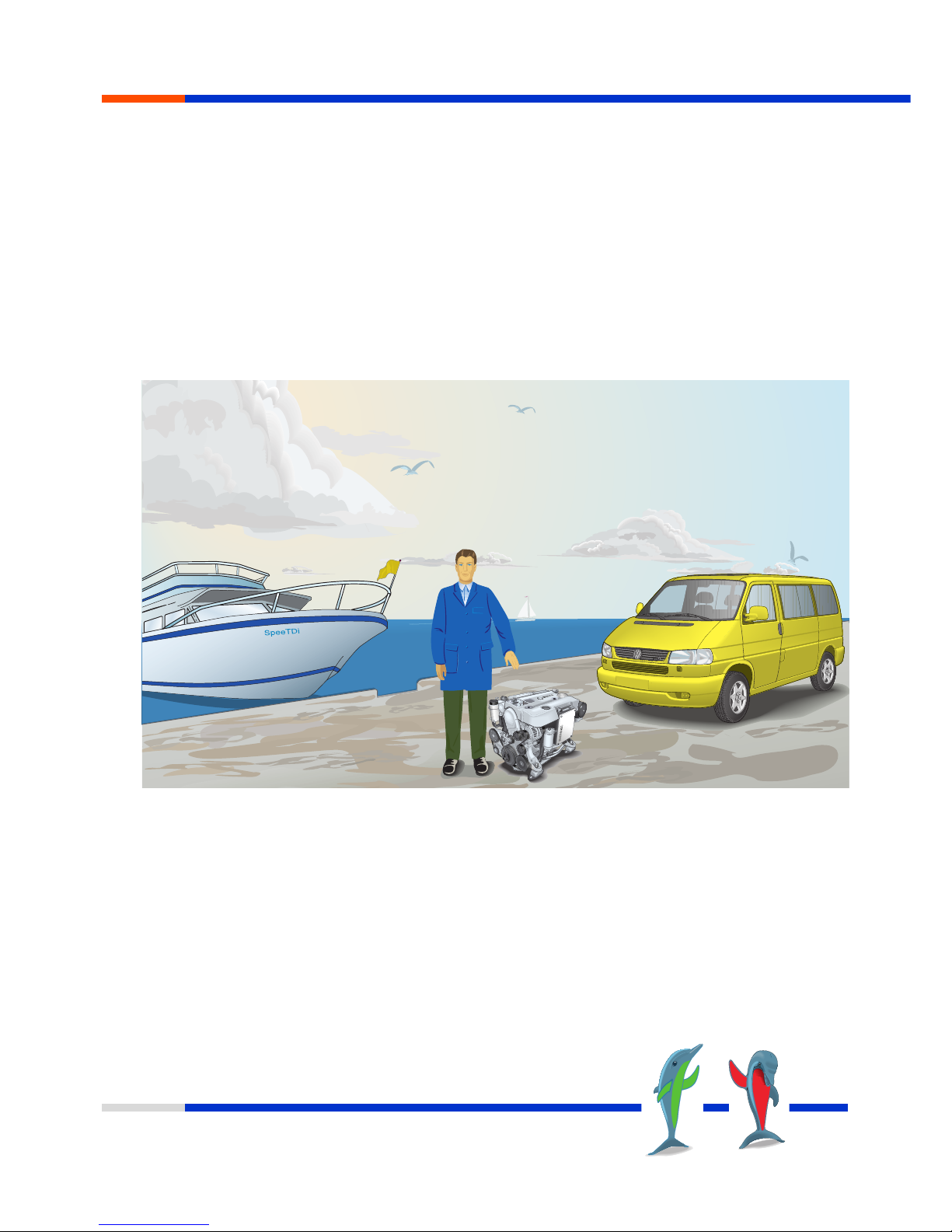
Volkswagen diesel engines have been providing dependable service in passenger vehicles and
transporters since 1976.
The development of TDI engines is a significant step in the direction of high technology.
With their sophisticated mechanical and electronic systems, low fuel consumption values and
outstanding power ratings, these diesel engines represent peak performance in diesel technology.
Boat engines from Volkswagen are developed by skippers for skippers.
The easy-to-service components as well as a worldwide parts organisation ensure reliable and efficient
operation over many years.
Foreword
MSSP_001_002
NEW

3
Superior Technology
Fundamentals . . . . . . . . . . . . . . . . . . . . . . . . . . . . . . . . .6
Features. . . . . . . . . . . . . . . . . . . . . . . . . . . . . . . . . . . . . . . . . . . . . . . 6
The SDI engine. . . . . . . . . . . . . . . . . . . . . . . . . . . . . . . . . . . . . . . . . 8
The TDI engine. . . . . . . . . . . . . . . . . . . . . . . . . . . . . . . . . . . . . . . . 10
Engine mechanical systems . . . . . . . . . . . . . . . . . . . . . 12
Engine oil circuit. . . . . . . . . . . . . . . . . . . . . . . . . . . . . . . . . . . . . . . 12
Cup-type oil filter. . . . . . . . . . . . . . . . . . . . . . . . . . . . . . . . . . . . . . 12
Electric oil extractor pump for oil change. . . . . . . . . . . . . . . . . . .13
Marine oil pan. . . . . . . . . . . . . . . . . . . . . . . . . . . . . . . . . . . . . . . . .13
Crankcase ventilation with oil separator. . . . . . . . . . . . . . . . . . . .13
Toothed belt drive for the camshaft. . . . . . . . . . . . . . . . . . . . . . . 14
Toothed belt drive for the distributor injection pump. . . . . . . . . 14
Ribbed V-belt drives for ancillary components . . . . . . . . . . . . . .15
Dual-mass flywheel . . . . . . . . . . . . . . . . . . . . . . . . . . . . . . . . . . . . 16
Hydraulic bucket tappet . . . . . . . . . . . . . . . . . . . . . . . . . . . . . . . . 18
Combustion system. . . . . . . . . . . . . . . . . . . . . . . . . . . .20
Two-spring nozzle holder . . . . . . . . . . . . . . . . . . . . . . . . . . . . . . . 21
Engine electronic systems. . . . . . . . . . . . . . . . . . . . . . .22
Overview of installation locations . . . . . . . . . . . . . . . . . . . . . . . .22
System overview. . . . . . . . . . . . . . . . . . . . . . . . . . . . . . . . . . . . . . . 24
Glow plug system. . . . . . . . . . . . . . . . . . . . . . . . . . . . . . . . . . . . . . 26
Intake manifold pressure and intake air temperature sender . 27
Needle lift sender . . . . . . . . . . . . . . . . . . . . . . . . . . . . . . . . . . . . . 28
Modulating piston movement sender . . . . . . . . . . . . . . . . . . . . . 29
Engine speed sender. . . . . . . . . . . . . . . . . . . . . . . . . . . . . . . . . . . 30
Coolant temperature sender. . . . . . . . . . . . . . . . . . . . . . . . . . . . . .31
Fuel temperature sender. . . . . . . . . . . . . . . . . . . . . . . . . . . . . . . . 32
Throttle lever position sender . . . . . . . . . . . . . . . . . . . . . . . . . . . . 33
Metering adjuster . . . . . . . . . . . . . . . . . . . . . . . . . . . . . . . . . . . . . 34
Start of injection valve. . . . . . . . . . . . . . . . . . . . . . . . . . . . . . . . . . 35
Fuel shut-off valve. . . . . . . . . . . . . . . . . . . . . . . . . . . . . . . . . . . . . 36
Indicator lamp for glow plug system monitoring
and engine electronics . . . . . . . . . . . . . . . . . . . . . . . . . . . . . . . . . 37
Fuel volume control. . . . . . . . . . . . . . . . . . . . . . . . . . . . . . . . . . . . 38
Start of injection control . . . . . . . . . . . . . . . . . . . . . . . . . . . . . . . . 39
Internal functions in the engine control unit . . . . . . . . . . . . . . . . 42
Function diagram. . . . . . . . . . . . . . . . . . . . . . . . . . . . . . . . . . . . . . 44
Table of Contents

4
Superior Technology
Table of Contents
Fuel system . . . . . . . . . . . . . . . . . . . . . . . . . . . . . . . . . .46
Fuel supply . . . . . . . . . . . . . . . . . . . . . . . . . . . . . . . . . . . . . . . . . . . 46
Diesel fuel microfilter with water warning facility . . . . . . . . . . . 48
Circulation preliminary filter with water separator (optional). . 50
Emission characteristics . . . . . . . . . . . . . . . . . . . . . . . .52
Pollutants in exhaust gas. . . . . . . . . . . . . . . . . . . . . . . . . . . . . . . . 52
Reducing pollutants. . . . . . . . . . . . . . . . . . . . . . . . . . . . . . . . . . . . 53
Exhaust turbocharging . . . . . . . . . . . . . . . . . . . . . . . . .54
Fundamental principle of exhaust turbocharging . . . . . . . . . . . 54
Turbocharger with variable turbine geometry . . . . . . . . . . . . . . 56
Control of variable guide vanes . . . . . . . . . . . . . . . . . . . . . . . . . 58
Guide vane adjustment. . . . . . . . . . . . . . . . . . . . . . . . . . . . . . . . . 59
Cooling system . . . . . . . . . . . . . . . . . . . . . . . . . . . . . . .60
Introduction to cooling system . . . . . . . . . . . . . . . . . . . . . . . . . . . 60
Overview of cooling circuit for SDI engines. . . . . . . . . . . . . . . . 60
Overview of cooling circuit for TDI engines . . . . . . . . . . . . . . . . 62
Design of cooler assembly . . . . . . . . . . . . . . . . . . . . . . . . . . . . . . 64
Intercooler. . . . . . . . . . . . . . . . . . . . . . . . . . . . . . . . . . . . . . . . . . . . 64
Main heat exchanger . . . . . . . . . . . . . . . . . . . . . . . . . . . . . . . . . . 65
Exhaust header . . . . . . . . . . . . . . . . . . . . . . . . . . . . . . . . . . . . . . . 65
Exhaust manifold. . . . . . . . . . . . . . . . . . . . . . . . . . . . . . . . . . . . . . 66
Combined cooler. . . . . . . . . . . . . . . . . . . . . . . . . . . . . . . . . . . . . . 66
Seawater pump . . . . . . . . . . . . . . . . . . . . . . . . . . . . . . . . . . . . . . . 67
Sacrificial anode . . . . . . . . . . . . . . . . . . . . . . . . . . . . . . . . . . . . . . 68
Electrical system . . . . . . . . . . . . . . . . . . . . . . . . . . . . . .69
Central electrics unit . . . . . . . . . . . . . . . . . . . . . . . . . . . . . . . . . . . 69
Earth cutout relay . . . . . . . . . . . . . . . . . . . . . . . . . . . . . . . . . . . . . 69
Multifunction display. . . . . . . . . . . . . . . . . . . . . . . . . . . . . . . . . . . 70
Displays/indicators – rev counter, voltmeter
and oil pressure gauge. . . . . . . . . . . . . . . . . . . . . . . . . . . . . . . . . 72

5
Superior Technology
Table of Contents
Self-diagnosis . . . . . . . . . . . . . . . . . . . . . . . . . . . . . . . .73
Diagnosis . . . . . . . . . . . . . . . . . . . . . . . . . . . . . . . . . . . . . . . . . . . . 73
Function 01 to 08 . . . . . . . . . . . . . . . . . . . . . . . . . . . . . . . . . . . . . . 74
Examples of fault code memory entries . . . . . . . . . . . . . . . . . . . 76
Monitored sensor
e.g. coolant temperature sender . . . . . . . . . . . . . . . . . . . . . . . . . 78
Adaptation kits . . . . . . . . . . . . . . . . . . . . . . . . . . . . . . .80
Gearbox bell housing for Volvo SP-E/DP-E . . . . . . . . . . . . . . . . 80
Gearbox bell housing for reversing gearbox (SAE-7) . . . . . . . .80
Gearbox bell housing for Mercruiser . . . . . . . . . . . . . . . . . . . . . 81
Gearbox bell housing for Volvo SX/DP-S. . . . . . . . . . . . . . . . . . 81
Abbreviations . . . . . . . . . . . . . . . . . . . . . . . . . . . . . . . .82
List of abbreviations used. . . . . . . . . . . . . . . . . . . . . . . . . . . . . . . 82

6
Superior Technology
Features
• Quiet-running 5-cylinder engines
• Low weight and compact dimensions
• 2-pole electrical system:
To avoid galvanic corrosion, the engine is not
connected to ground
• Electric oil intake pump and upright cup-type
oil filter for clean and efficient oil change at
the push of a button
• Oil pan with support feet and baffle plates for
increased protection when listing and in
rough seas
• Low-maintenance belt drives with automatic
tensioning elements to ensure long service life
of belts and components
• Ultramodern electronics for monitoring
engine functions
• Warnings with visual and acoustic alarm
• Water-cooled turbocharger with Variable
T
urbine Geometry (VTG) for high propelling
power in a wide speed range
• Powerful three-phase alternators for reliable
power supply and fast battery charging
• All engines comply with the currently valid
and most stringent pollution standard, the
Bodensee Schifffahrtsverordnung (Lake
Constance Shipping Ordinance) BSO II also
with twin motorisation
• Complete instrumentation with economy
control
• Suitable for PME/RME fuel
Fundamentals
Particular care must be taken to
ensure that the fuel tank and
the fuel hoses leading to the
engine are also suitable for
PME/RME fuel.
7
Superior Technology
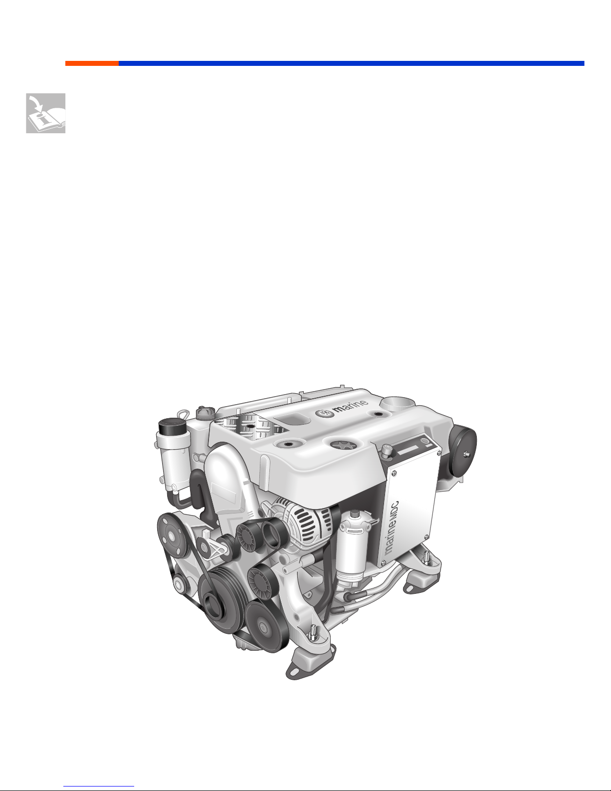
The Volkswagen Marine boat engines feature
• a special Marine Diesel Control (MDC) system
specifically adapted to boat operation and
which is characterized by maximum reliability.
An emergency running program with a
regeneration function ensures reliable engine
operation should, contrary to expectations, a
malfunction occur.
• a wide effective engine speed range with high
propelling power.
• extensive corrosion protection for the engine
housing and all add-on components.
• a dual-mass flywheel to absorb drive and
transmission vibrations.
Fundamentals
MSSP_001_003
8
Superior Technology
The SDI engine
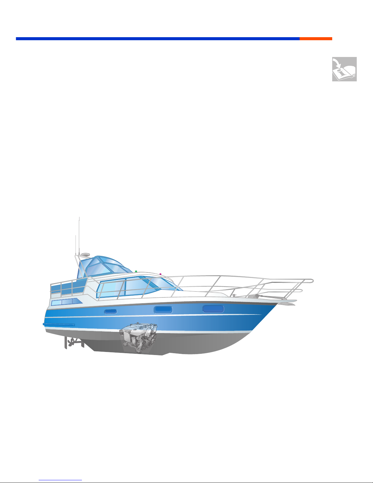
The Volkswagen Marine boat engines are
designed as naturally aspirated diesel engines
with direct injection for use in displacement
boats.
The engines, well-proven a million times over,
offer:
• Quiet operation despite high pressure direct
injection
• Low engine speed level and low-vibration
operation
• High torque and low fuel consumption
• Low pollutant emission
• Compact installation dimensions
• Ease of maintenance and
• Ultramodern technology
Fundamentals
MSSP_001_004
9
Superior Technology
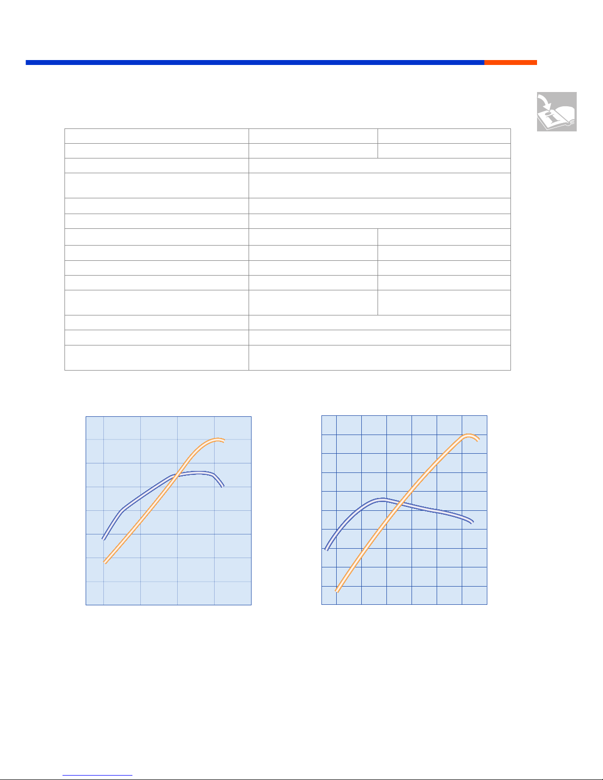
Engine data
Marine Type
SDI 55-5 SDI 75-5
Engine code letter
BCT ANF
Engine design
5-cylinder in-line naturally aspirated diesel engine
Fuel injection system
Diesel direct injection with electronically controlled
distributor-type injection pump
Displacement
2461 cm
3
Compression ratio
19.0 : 1
Power rating at engine speed
40 kW (55 bhp) 2500 rpm 55 kW (75 bhp) 3600 rpm
Max. torque at engine speed
155 Nm 2250 rpm 155 Nm 2250 rpm
Specific power output
16.3 kW/l 22.3 kW/l
Min. specific fuel consumption
233 g/kWh 233 g/kWh
Weight (dry, with ancillary components, cooling
system and clutch flange) not including gearbox
260 kg 260 kg
Alternator
120 A
Electrical system
12 V not earthed
Exhaust emission legislation, certified in accordance with
Bodensee Schifffahrtsverordnung Stufe 2 (Lake Constance Shipping
Ordinance, Stage 2)
45
40
35
30
25
1000 1500 2000 2500
20
160
150
140
130
15
10
5
45
50
55
60
40
35
30
25
1000 1500 2000 2500 3000 3500
20
160
150
140
130
15
10
Fundamentals
MSSP_001_110
MSSP_001_109
Output (kW)
Engine speed (rpm)
Output (kW)
Torque (Nm)
Torque (Nm)
Output (kW)
Engine speed (rpm)
Output (kW)
Torque (Nm)
Torque (Nm)
SDI 55-5 SDI 75-5

10
Superior Technology
50
70
60
80
90
40
30
1500 2000 2500 3000
20
280
240
200
160
10
0
The TDI engine
Volkswagen Marine boat engines
are designed as direct injection
engines with turbocharging for use
in displacement and hydroglider
boats.
The TDI 150-5 is particularly
suitable for use in fast hydroplanes.
The TDI 150-5D variant is certified
for use as twin motorisation in
compliance with BSO II.
The TDI 100-5 and 120-5 engines
are perfectly adapted to use in
touring and sailing boats. They are
both also certified for use as twin
motorisation in compliance with
BSO II.
The TDI engines feature a
turbocharger with a water-cooled
VTG turbocharger
(Variable Turbine Geometry).
The engines develop a wide effective speed
range offering high propelling po wer without the
characteristic propulsion weakness of
turbocharged engines in the lower engine speed
range.
Fundamentals
MSSP_001_111
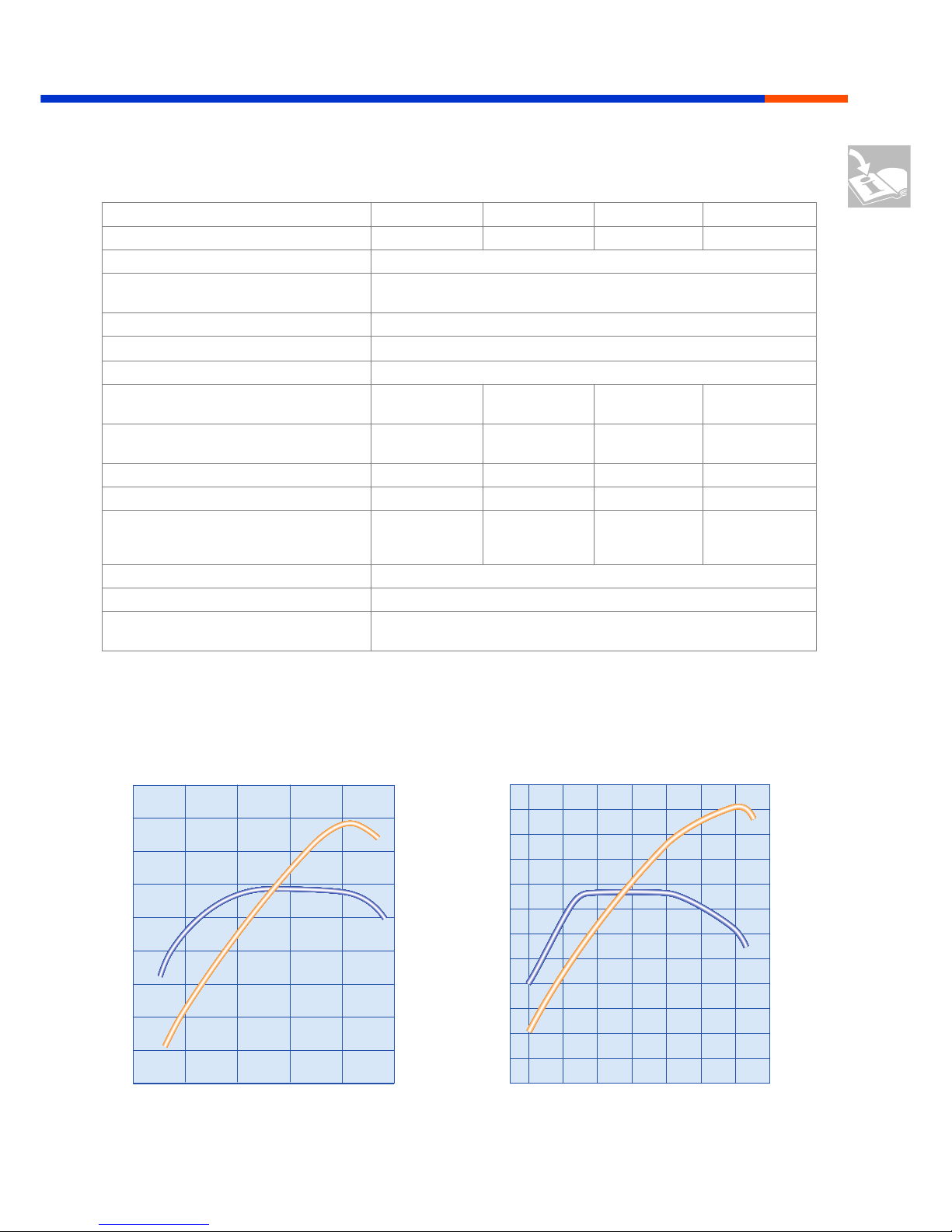
TDI 100-5
Output (kW)
Engine speed (rpm)
Output (kW)
Torque (Nm)
Torque (Nm)
MSSP_001_005
11
Superior Technology
50
70
60
80
90
100
120
110
40
30
15001000
290
320
260
230
35002000 2500 3000 4000
20
10
0
Engine data
Marine Type
TDI 100-5 TDI 120-5 TDI 150-5 TDI 150-5D
Engine code letter
BCU ANG ANH BCV
Engine design
5-cylinder in-line turbocharged diesel engine
Fuel injection system
Diesel direct injection with electronically controlled
distributor-type injection pump
Supercharging
Variable turbocharger (VTG)
Displacement
2461 cm
3
Compression ratio
19.0 : 1
Power rating at engine speed
74 kW (100 bhp)
2600 rpm
88 kW (120 bhp)
3250 rpm
111 kW (150 bhp)
4000 rpm
108 kW (147 bhp)
4000 rpm
Max. torque at engine speed
270 Nm
2500 rpm
275 Nm
2500 rpm
310 Nm
1900 rpm
310 Nm
1900 rpm
Specific power output
30.1 kW/l 35.8 kW/l 45.1 kW/l 43.9 kW/l
Min. specific fuel consumption
217 g/kWh 217 g/kWh 203 g/kWh 203 g/kWh
Weight (dry, with ancillary components,
cooling system and clutch flange) not including gearbox
275 kg 275 kg 280 kg 280 kg
Alternator
120 A
Electrical system
12 V not earthed
Exhaust emission legislation, certified in
compliance with
Bodensee Schifffahrtsverordnung Stufe 2 (Lake Constance Shipping
Ordinance, Stage 2)
50
70
60
80
90
100
40
30
1500
280
240
200
2000 2500 3000
20
10
Fundamentals
TDI 120-5
MSSP_001_112 MSSP_001_113
TDI 150-5
Output (kW)
Engine speed (rpm)
Output (kW)
Torque (Nm)
Torque (Nm)
Output (kW)
Engine speed (rpm)
Output (kW)
Torque (Nm)
Torque (Nm)
12
Superior Technology
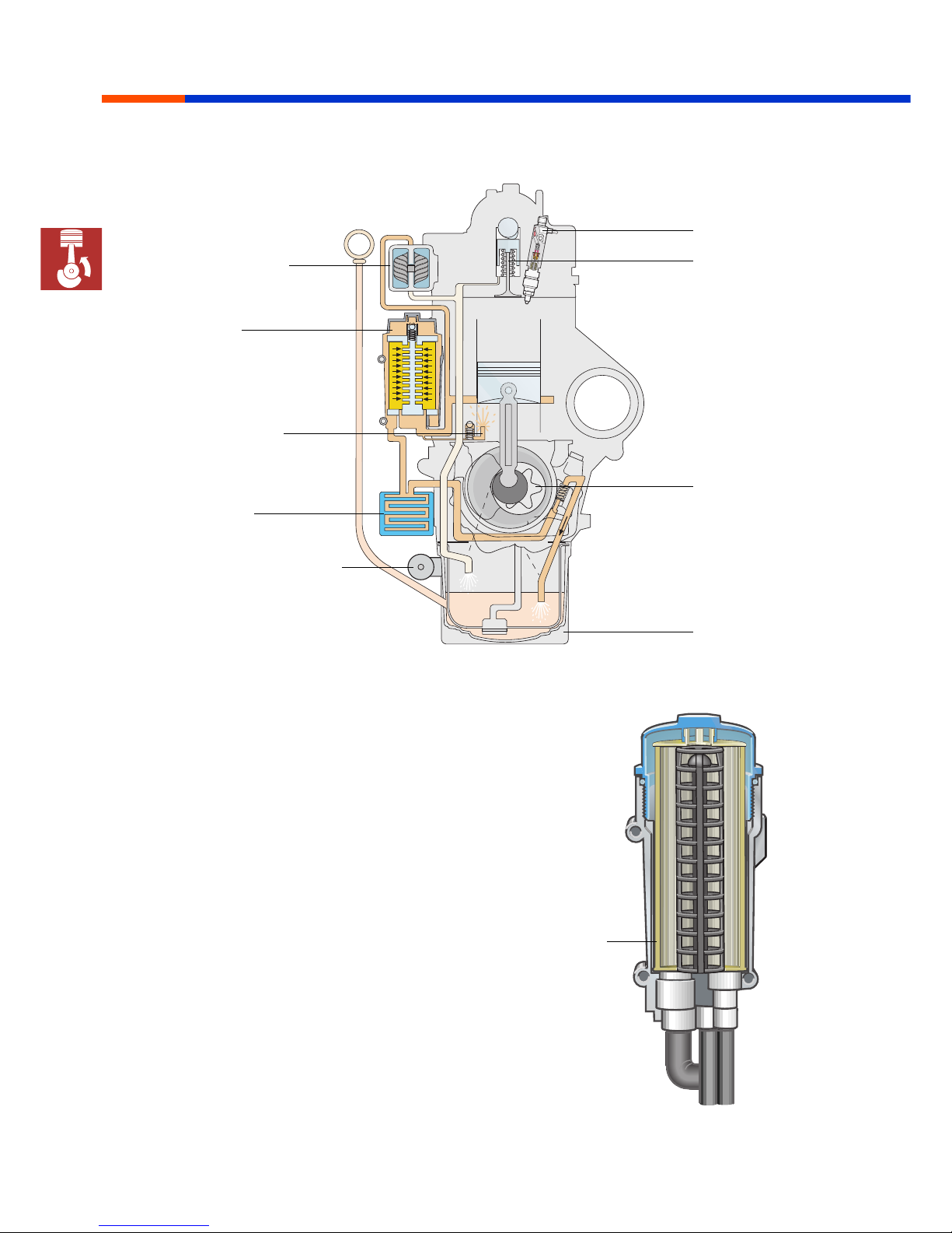
Engine oil circuit
Cup-type oil filter
The cup oil filter is arranged upright. The paper
filter that can be replaced from the top ensures
the filter is easy to service and environmentally
compatible.
When the oil filter cover is opened, a valve also
opens so that the oil can flow out of the filter
housing through a separate line back into the oil
pan.
Engine mechanical systems
MSSP_001_011
MSSP_001_073
Oil filter
Oil cooler
Oil spray nozzle
for piston cooling
Oil pump
Turbocharger with
variable turbine
geometry
Injection nozzle
Hydraulic tappet
Marine oil pan
Electric oil extractor pump
for oil change
Filter element
13
Superior Technology
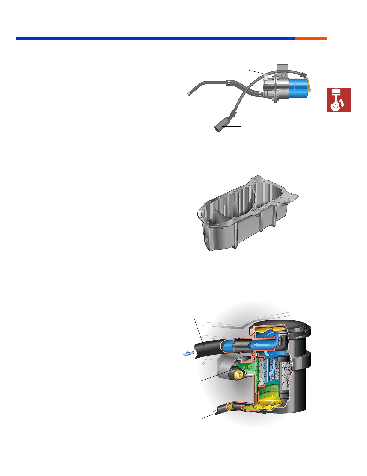
Electric oil extractor pump
The electric oil extractor pump can be used to
extract the engine oil in an environmentally
friendly manner and free of drips.
The pump is switched on by the switch on the
central electrics unit.
Oil pan
The oil pan is designed specially for use in
Volkswagen Marine boat engines. Baffle plates
ensure reliable oil supply to the engine also when
listing heavily and in rough seas.
Crankcase ventilation
with oil separator
The crankcase ventilation system with oil
separator serves the purpose of keeping the air
clean (to minimize oil burning) and prevents oil
deposits forming on the intercooler.
The oil vapours pass through the crankcase
ventilation system into the oil separator. The
fabric element contained in the oil separator
separates oil droplets and blow-by gas. The oil
droplets are collected on the base and returned
to the oil pan. The blow-by gas is routed back
into the intake manifold of the engine.
The fabric element need not be replaced.
Engine mechanical systems
MSSP_001_107
MSSP_001_103
MSSP_001_104
To intake pipe
From crankcase
ventilation
To oil pan
To collection reservoir
From oil pan
Electric connection
14
Superior Technology
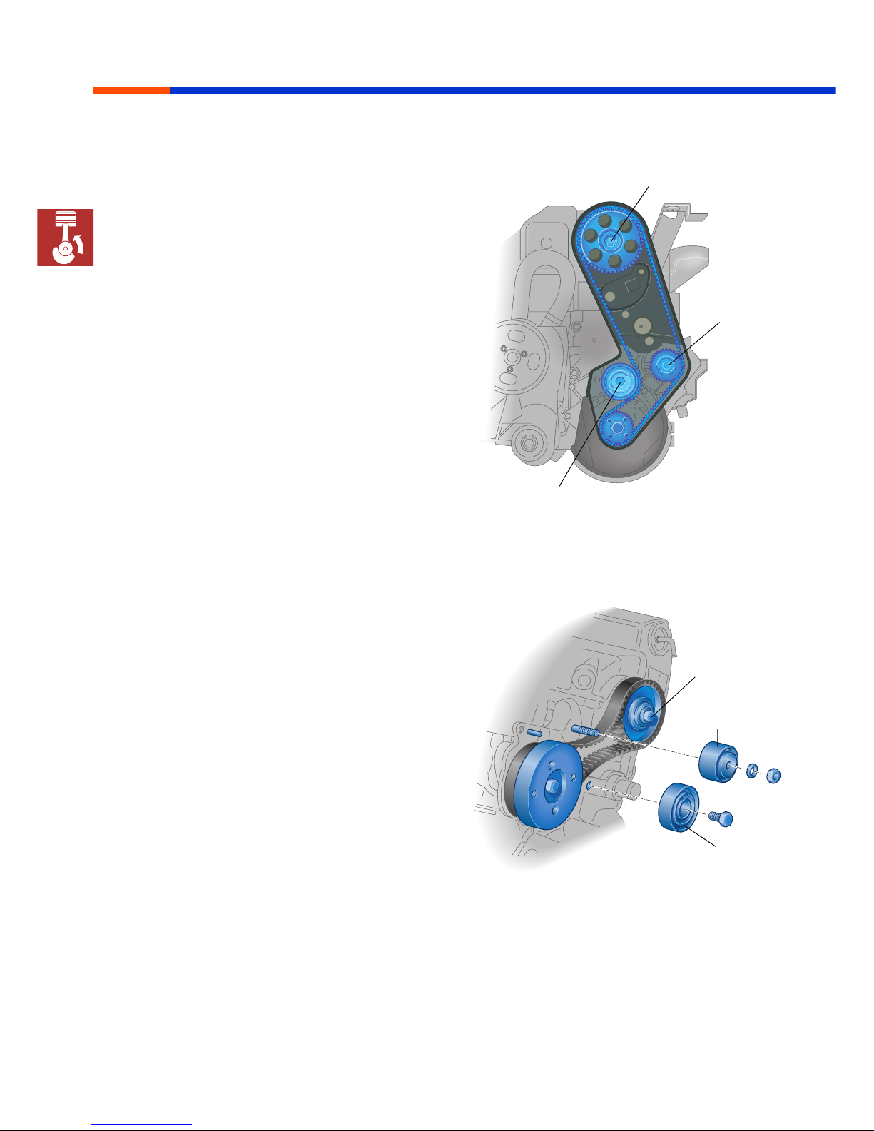
Belt drives
Toothed belt drive for the camshaft
The toothed belt drives
• the camshaft and
• the coolant pump.
The mechanical tension of the toothed belt is
controlled by a tension pulley.
Toothed belt drive for the distributor injection
pump
The toothed belt drive for the distributor-type
injection pump consists of the tension pulley,
deflection pulley, drive gearwheel that is driven
by the camshaft, injection pump gearwheel as
well as the toothed drive belt.
Engine mechanical systems
MSSP_001_007
MSSP_001_006
Tension pulley
Deflection
pulley
Camshaft
Tension pulley
Coolant
pump
Camshaft
15
Superior Technology
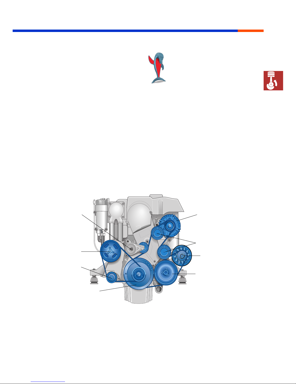
Ribbed V-belt drives for
ancillary components
The ancillary components are driven by ribbed
V-belts.
The following components are driven:
• The alternator (12 V) for engine operation and
battery charging
•
Optional
The power steering pump for boats with
Z-drive
•
and optional
An additional 12 V, 24 V or 230 V alternator
• The seawater pump via a separate ribbed
V-belt drive
The belt drives are equipped with automatic belt
tensioners and therefore require little
maintenance.
Engine mechanical systems
MSSP_001_008
To avoid damage to the vibration
damper and the engine, the engine
must not be run without the
alternator belt drive.
Please refer to the curr ent Workshop
Manual for instructions on all
adjustment and repair work.
12 V alternator
Deflection pulley
Power steering pump
Belt tensioner
Seawater pump
Belt tensioner
Vibration damper
2nd alternator
16
Superior Technology
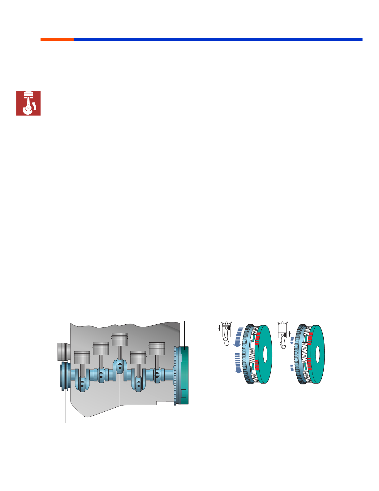
Dual-mass flywheel
Due to irregularities in combustion, displacement
engines produce torsional vibrations at the
crankshaft and the flywheel.
The use of a dual-mass flywheel prevents these
torsional vibrations being transmitted into the
drive train where they w ould produce r esonance,
resulting in disturbing noise in the boat. The
dual-mass flywheel therefore also avoids
excessive stress in the subsequently connected
gearbox.
The dual-mass flywheel divides the flywheel mass
into two parts.
One part is the primary flywheel or centrifugal
mass; it belongs to the mass moment of inertia of
the engine.
The other part, the secondary mass, increases the
mass moment of inertia of the drive.
Connected by means of a spring damping
system, both decoupled masses isolate the
vibrations.
They absorb the vibrations at low engine speeds
thus ensuring "drive rattle" no longer occurs.
Engine mechanical systems
MSSP_001_010
MSSP_001_063
Vibration insulation
Vibration damper
Crankshaft drive
Primary flywheel mass of
the dual-mass flywheel
Secondary flywheel mass
17
Superior Technology
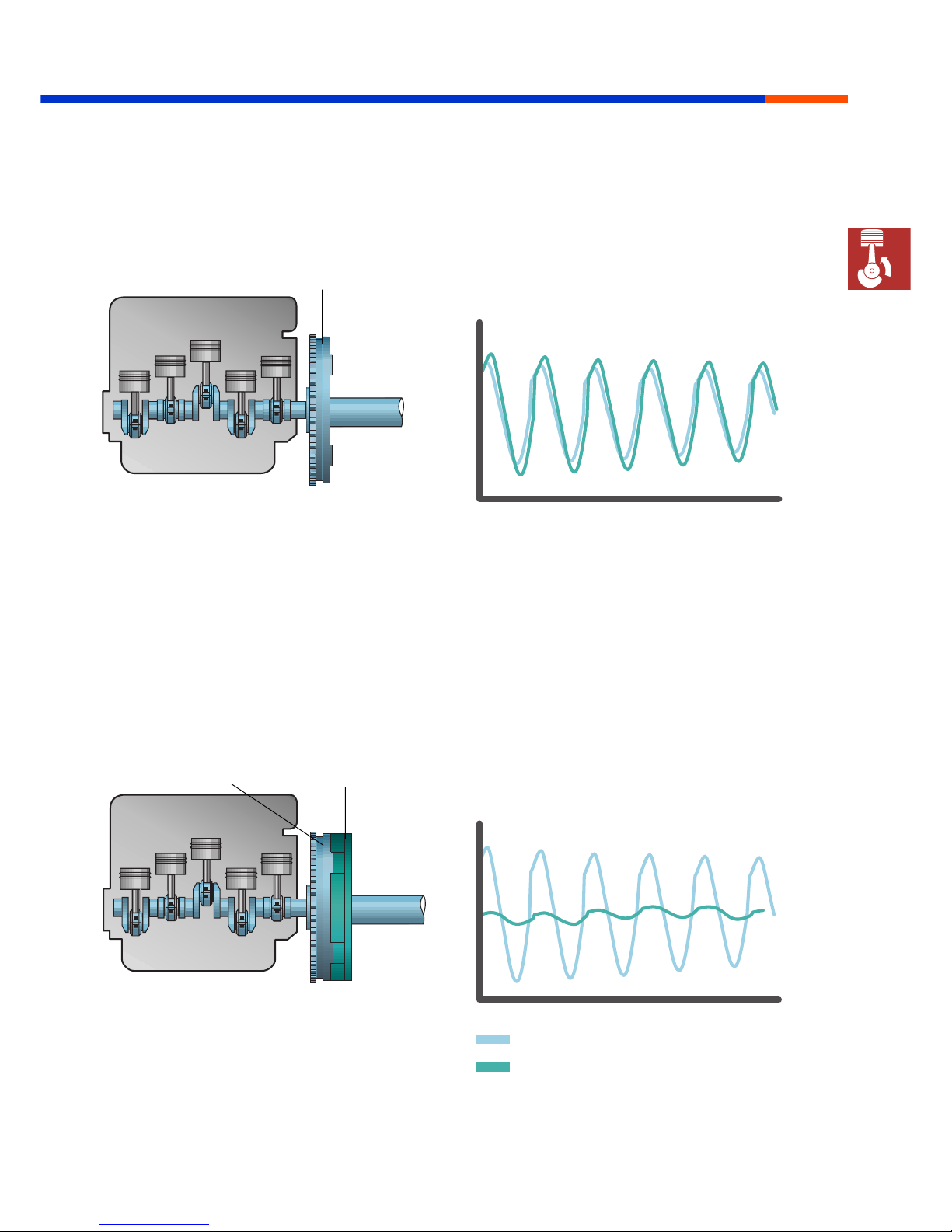
Conventional power transmission structure
without dual-mass flywheel
Engine and drive train vibrations at low engine
speed
Power transmission with dual-mass flywheel
Engine and drive train vibrations at low engine
speed
Engine mechanical systems
MSSP_001_065
MSSP_001_064
Flywheel
Primary flywheel mass Secondary flywheel mass
MSSP_001_085
MSSP_001_084
Vibrations generated by the engine
Vibrations absorbed by the drive train
Engine and drive train vibration in idle
speed range
Engine and drive train vibration in idle speed
range

18
Superior Technology
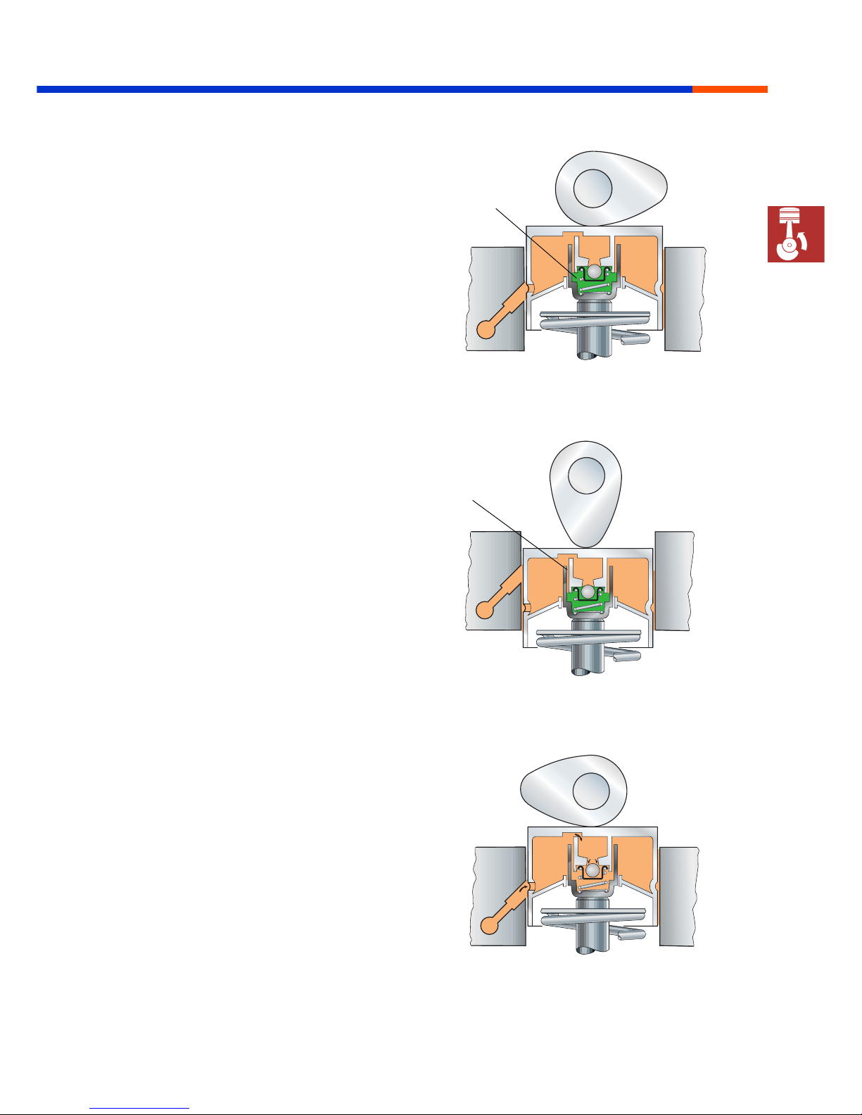
Hydraulic bucket tappet
All Volkswagen Marine boat engines are
equipped with hydraulic bucket tappets.
In addition to reducing noise, they also simplify
servicing:
• No need to check and adjust valve clearance
• Precision valve timing
The hydraulic bucket tappets essentially
comprise:
• Bucket tappet with piston
• Cylinder
• Non-return valve
Engine mechanical systems
Valve noise after starting the engine
is a normal occurrence. Oil is forced
out of the bucket tappet while the
engine is inoperative. As soon as the
engine is running, the high pressure
chamber is filled with oil again and
the valve noise disappears.
MSSP_001_012
Bucket tappet
Piston
Cylinder
Compression
spring
Camshaft
Oil reservoir
Non-return
valve
Oil feed
High pressure
chamber
Valve stem
19
Superior Technology
Functional description
Beginning of valve stroke
The cam turns on the bucket tappet, the
non-return valve closes and pr essure builds up in
the high pressure chamber. The oil trapped in the
high pressure chamber cannot be compressed.
The bucket tapped acts as a rigid element.
Valve stroke
The pressure in the high pressure chamber
increases due to the force the cam exerts on the
tappet. A little oil escapes via the leakage gap so
that the tappet compresses by max. 0.1 mm.
Valve clearance compensation
Compensation of the valve clearance (lash)
begins after the valve has closed. The pressur e in
the high pressure chamber drops as the cam no
longer presses against the tappet. The spring
forces the cylinder and bucket apart to such an
extent that there is no clearance between the
bucket tappet and cam. Oil flows out of the
supply reservoir through the now opening
non-return valve into the high pressure chamber.
Engine mechanical systems
MSSP_001_015
MSSP_001_013
High pressure
chamber
MSSP_001_014
Leakage gap
20
Superior Technology
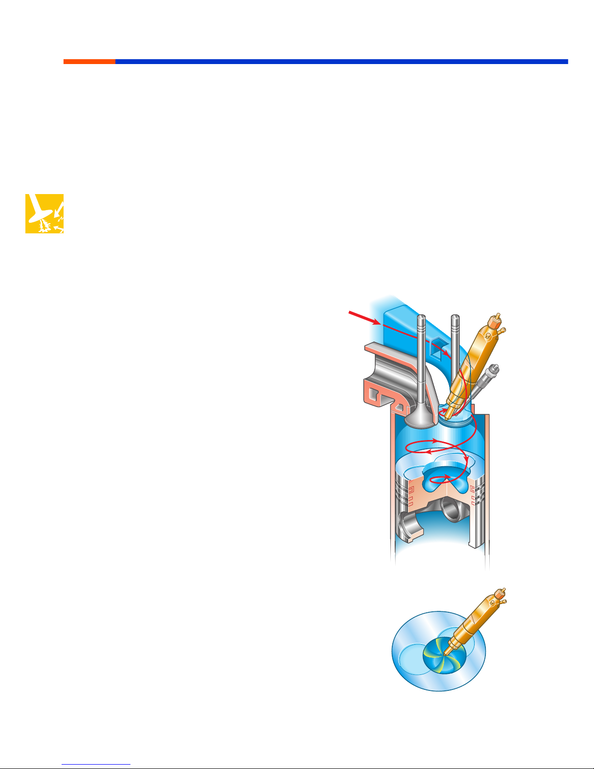
The combustion system
In Volkswagen Marine boat engines, the fuel is
injected directly into the main combustion
chamber.
The advantages include:
• More efficient combustion
• Improved fuel utilization
• Lower fuel consumption and
• Low pollutant emission
The special design of the pistons, injection
nozzles and of the intake port optimises the
combustion process with regard to noise
development, smooth operation and pollutant
emissions.
Intake swirl port
The special design of the intake port induces a
swirling motion in the drawn-in air.
Piston recess
The swirling motion of the intake air is continued
in the piston recess that is optimally adapted to
this engine.
Injection nozzle
The five-hole injection nozzle (fuel injector) injects
the fuel in two stages into the piston recess wher e
it ignites on the hot air.
The two-stage injection prevents a "harsh"
increase in pressure thus avoiding the
characteristic diesel "knock".
Combustion system
MSSP_001_016
21
Superior Technology
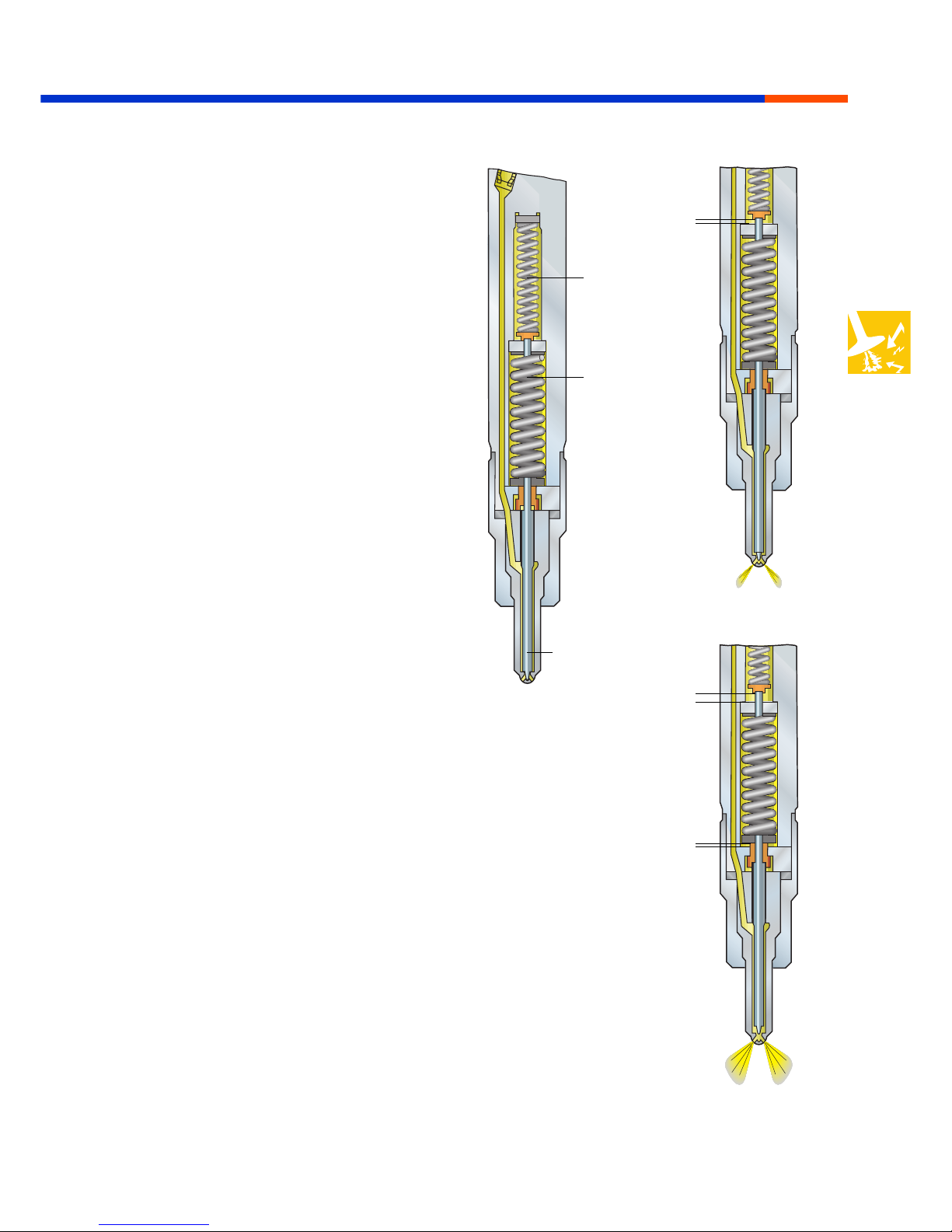
Two-spring nozzle holder
Smooth increase in pressure in the combustion
chamber reduces combustion noise and
mechanical stress.
The two-spring nozzle holder developed for the
Volkswagen direct injection diesel engines
enables fuel injection in two stages. As a result, it
plays an important part in ensuring "smooth"
combustion.
Functional description
There are two springs of different thickness fitted
in the nozzle holder. Due to the geometry of the
springs, the nozzle needle is raised only against
the force of the first spring at the start of
injection. A small gap is produced, allowing a
small quantity of fuel to be pre-injected at low
pressure. This pre-injection ensures a smooth
increase in the combustion pressure and creates
the ignition conditions for the main volume of
fuel. The pressure in the injection nozzle
increases due to the fact that the injection pump
delivers more fuel than escapes through the
small gap. The nozzle needle is further raised
against the force of the second spring. The main
injection now takes place at high pressure.
Combustion system
MSSP_001_017
Spring 1
Spring 2
Nozzle needle
Lift 1
Lift 1 and lift 2
Lift 2
22
Superior Technology
Engine electronic systems
marine
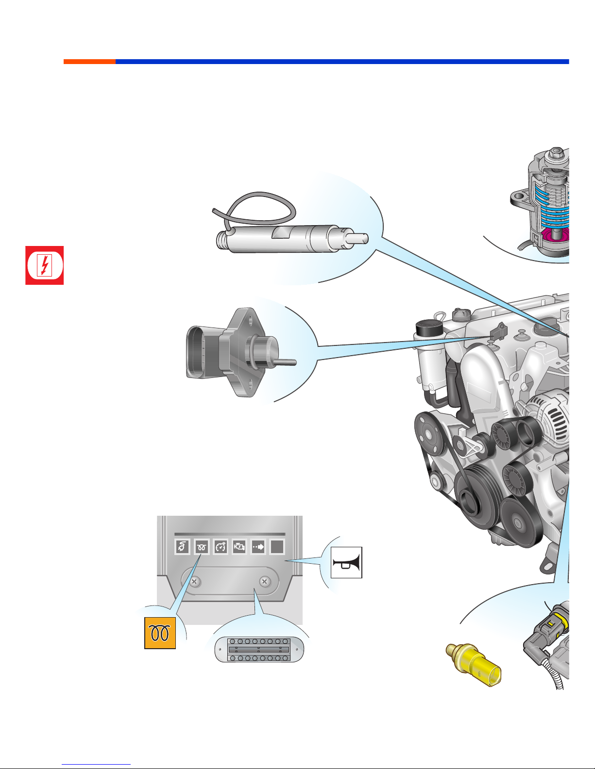
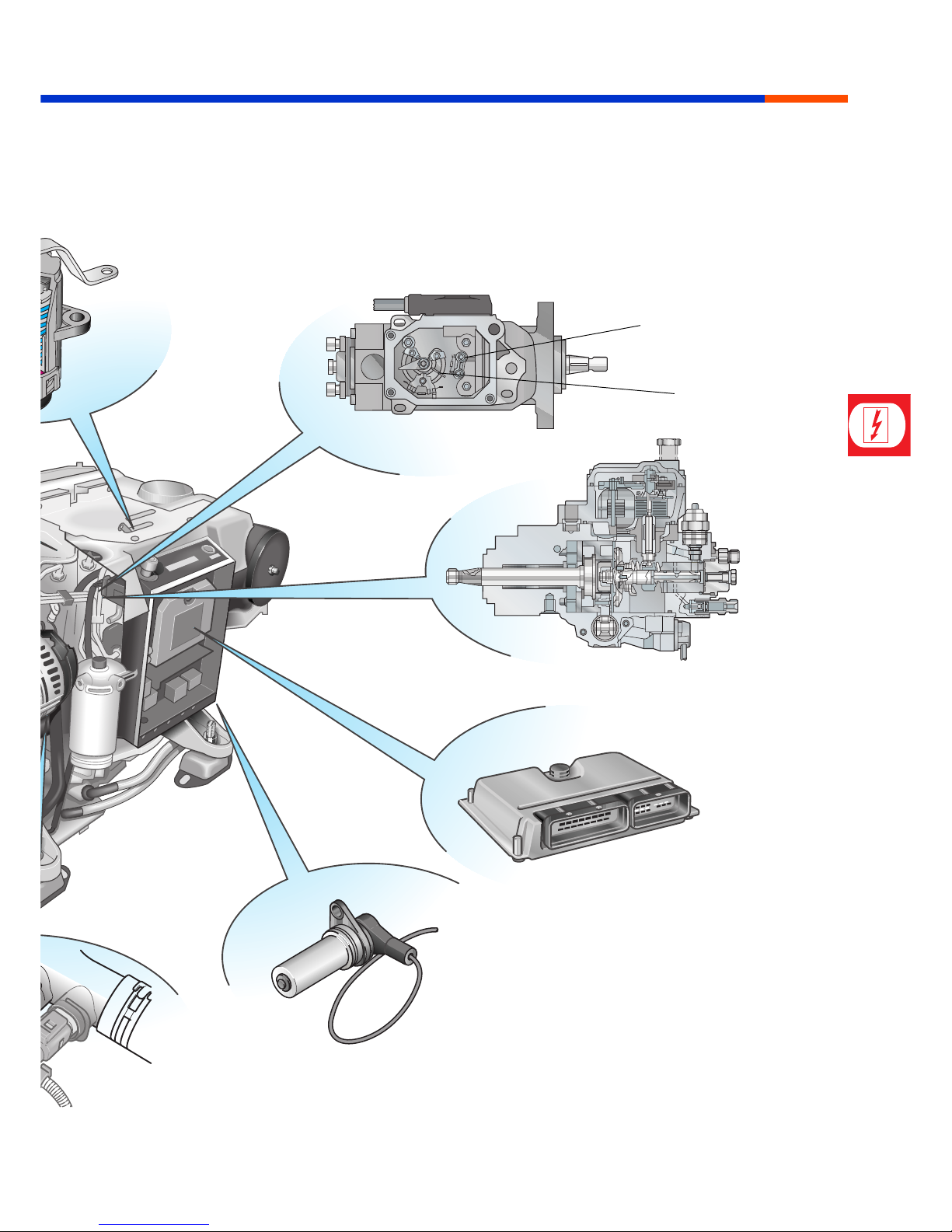
Overview of installation locations
This general layout provides an overview of the
components of the MDC. The components are
described in detail in the following chapters.
Needle lift sender at
injection nozzle of 5th cylinder
Intake manifold pressure
and intake air temperature sender
Indicator lamp for glow plug
system monitoring and
engine electronics
Throttle lever position sender
Diagnosis interface
Acoustic warner
Coolant temperature sender
23
Superior Technology
Engine electronic systems
MSSP_001_019
Fuel temperature sender
Modulating piston
movement sender
Distributor injection pump
MDC control unit
Engine speed sender
24
Superior Technology
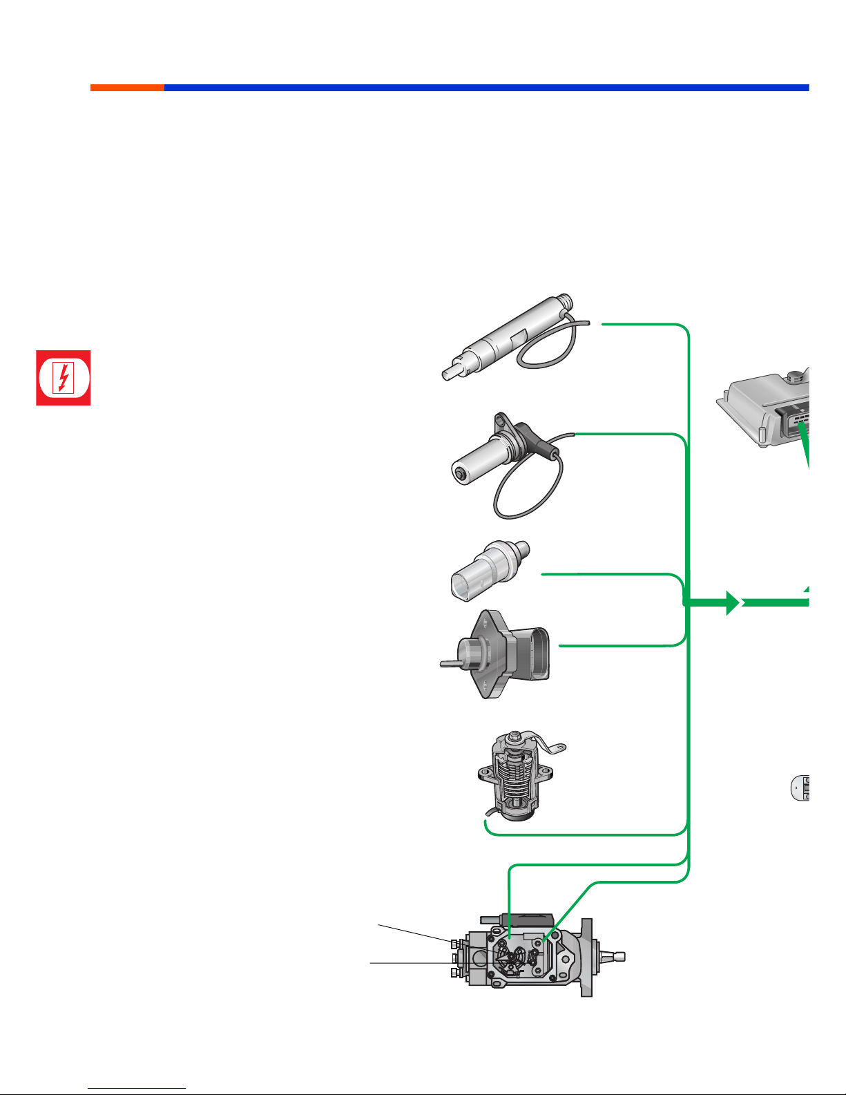
System overview
Sensors supply the engine control unit with
information on the current operating status of
the engine.
Engine electronic systems
Needle lift sender
Engine speed sender
Coolant temperature sender
Intake manifold and intake air
temperature sender
Throttle lever position sender
Modulating piston movement
sender
Fuel temperature sender
25
Superior Technology
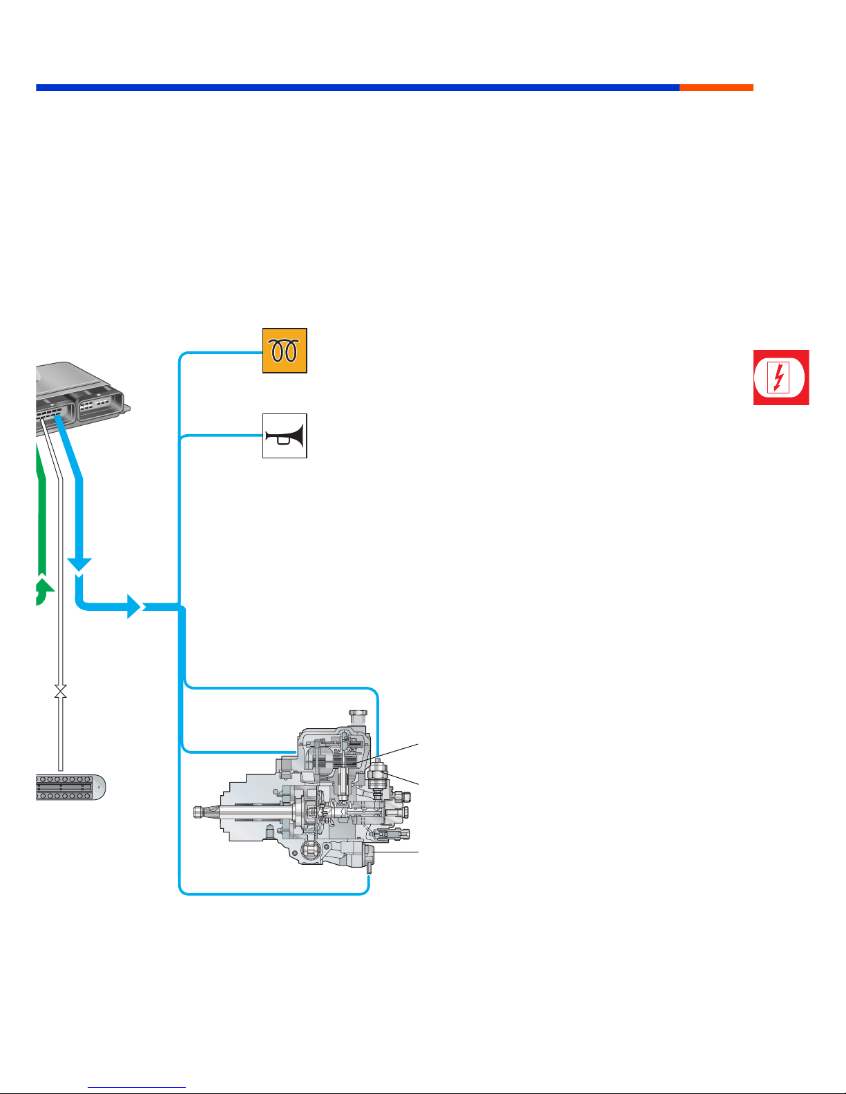
For monitoring purposes, the engine control unit
makes use of several characteristic maps and
characteristic curves while ensuring the best
torque output, the most favourable fuel
consumption and the best exhaust emission
characteristics for every operating situation.
Engine electronic systems
MSSP_001_020
The corresponding actuators are activated
following evaluation of the sensor information in
the engine control unit.
The injection volume and start of injection as well
as the preheater system are controlled and
monitored in this way.
Metering adjuster
Indicator lamp for glow plug system
monitoring and engine electronics
Valve for fuel shut-off
Valve for start of injection
Diagnosis
connector
MDC control unit
Acoustic warner
26
Superior Technology
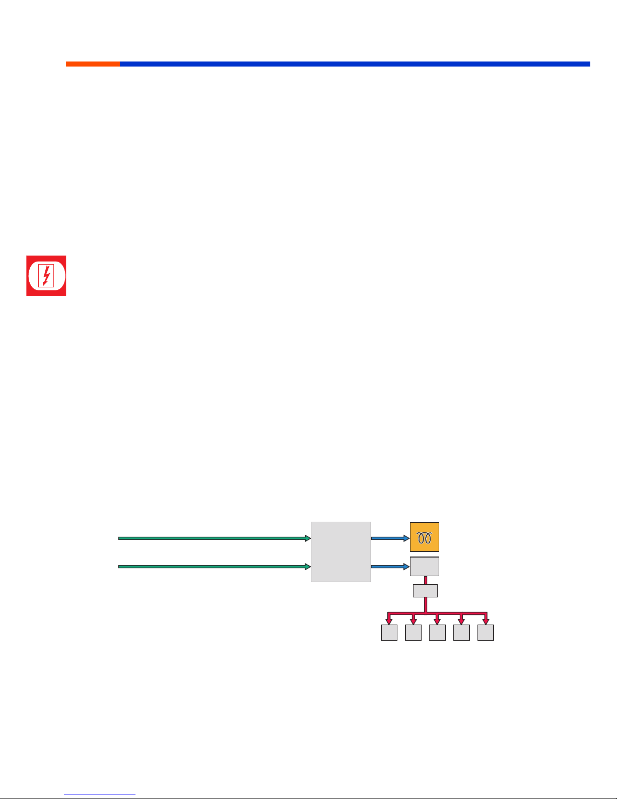
Glow plug system
A glow plug system control is integrated in the
Volkswagen Marine engine control unit.
The glow plug control contains the following
functions:
• Preheating
• Post-heating
• Standby heating
Functional description
Preheating
In view of the outstanding starting characteristics
of the Volkswagen Marine direct injection boat
engines, preheating (glow plug) is only activated
at temperatures below +9 °C. The engine control
unit receives the signal for the engine
temperature from the coolant temperature
sender.
The preheating procedure is started
automatically. The preheating time depends on
the current engine temperature.
An indicator lamp in the panel informs the
skipper that preheating is active.
Engine electronic systems
MSSP_001_045
Engine speed Pin 8
Coolant temperature Pin 14
Pin 26
Pin 50
Indicator lamp for glow
plug system monitoring
and engine electronics
Relay for glow plugs
FuseMDC control unit
Q6 Q6 Q6 Q6 Q6
Glow plugs
 Loading...