

Page 1
Service.
Self-Study Programme 248
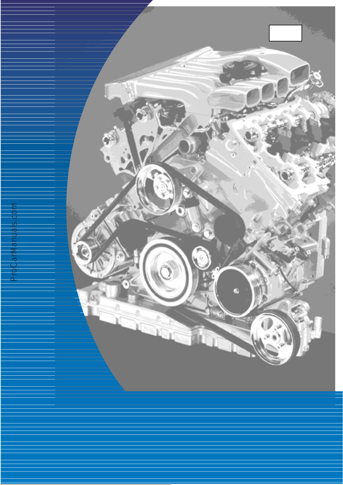
The W Engine Concept
Design and Function
Page 2
Introduction
The constantly rising demands regarding
performance, running comfort and fuel economy
have led to the advancement of existing drive
units and the development of new drive units.
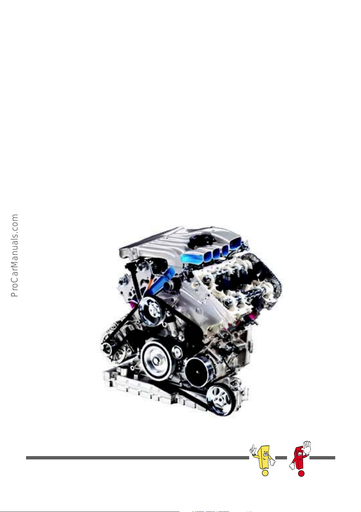
The new W8 as well as the W12 engine by
VOLKSWAGEN are representatives of a new
engine generation - the W engines.
The W engines set exacting demands on design.
Large numbers of cylinders were adapted to the
extremely compact dimensions of the engine.
In the process, more attention was paid to
lightweight design.
This Self-Study Programme will familiarise you
with the engine mechanicals of the W engine
family.
This Self-Study Programme explains the design
and function of new developments.
The contents will not be updated!
S248_101
New Important
Note
Please always refer to the relevant Service Literature for current inspection, adjustment and repair instructions.
2
Page 3
At a glance
Introduction . . . . . . . . . . . . . . . . . . . . . . . . . . . . . . . . . . .4
Engine mechanicals . . . . . . . . . . . . . . . . . . . . . . . . . . .10
Specifications . . . . . . . . . . . . . . . . . . . . . . . . . . . . . . . . 10
The crankshaft drive . . . . . . . . . . . . . . . . . . . . . . . . . . . . 14
The engine in detail . . . . . . . . . . . . . . . . . . . . . . . . . . . 15
The chain drive . . . . . . . . . . . . . . . . . . . . . . . . . . . . . . . 28
The camshaft timing control . . . . . . . . . . . . . . . . . . . . 29
The belt drive . . . . . . . . . . . . . . . . . . . . . . . . . . . . . . . . 32
The oil circuit . . . . . . . . . . . . . . . . . . . . . . . . . . . . . . . . . 34
The coolant circuit . . . . . . . . . . . . . . . . . . . . . . . . . . . . 42
The air supply . . . . . . . . . . . . . . . . . . . . . . . . . . . . . . . . 46
The exhaust system . . . . . . . . . . . . . . . . . . . . . . . . . . . . 50
Service . . . . . . . . . . . . . . . . . . . . . . . . . . . . . . . . . . . . . .52
Sealing concept . . . . . . . . . . . . . . . . . . . . . . . . . . . . . . 52
Engine timing overview. . . . . . . . . . . . . . . . . . . . . . . . . 54
Special tools . . . . . . . . . . . . . . . . . . . . . . . . . . . . . . . . . 56
3
Page 4
Introduction
W engines - what does the W stand for?
With the aim of building even more compact
units with a large number of cylinders, the design
features of the V and VR engines were combined
to produce the W engines.
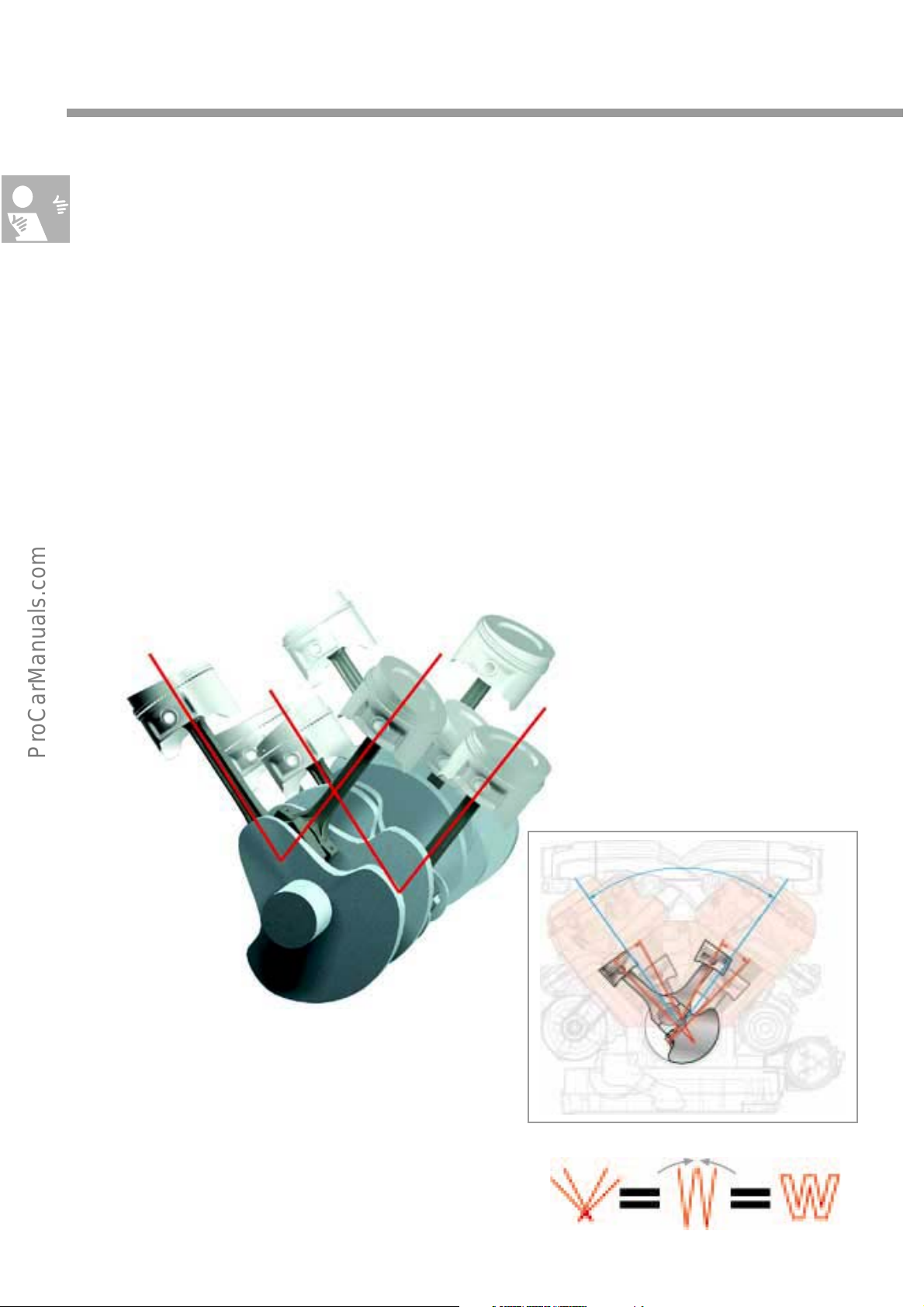
As with the V engines, the cylinders are
distributed to two banks. In the W8 and W12
engines, these banks of cylinders are aligned at
a V-angle of 72° in relation to one another. As in
the VR engine, the cylinders within each bank
maintain an angle of 15°.
When the W engine is viewed from the front, the
cylinder arrangement looks like a double-V.
Put the two Vs of the right and left cylinder banks
together, and you get a W. This is how the name
"W engine" came about.
S248_104
15°
72°
15°
S248_002
S248_001
4
Page 5
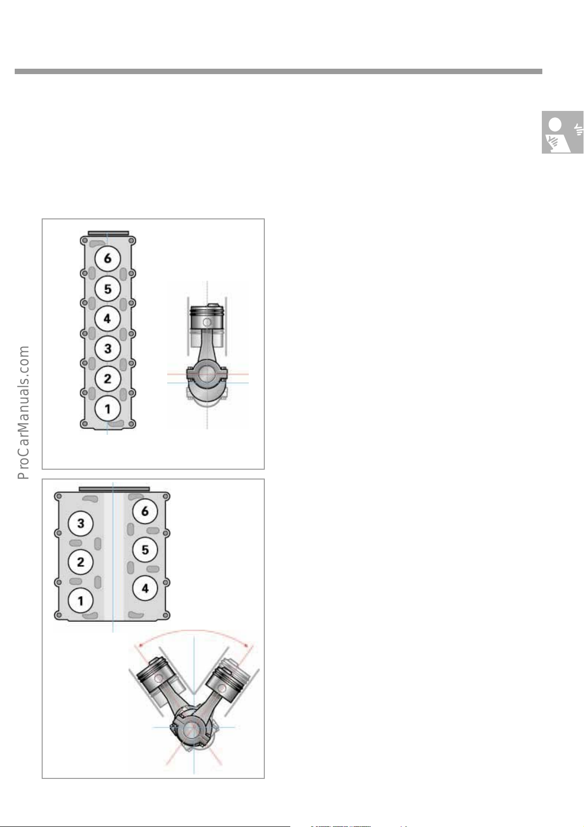
The W principle
To illustrate the principle of the W engine cylinder arrangement, we will first show you conventional
engine types.
The inline engine
Represents the earliest development level in
engine development. The cylinders are arranged
in-line vertically above the crankshaft.
Advantage: Simple design
Drawback: Large numbers of cylinders result in
very long units unsuitable for transverse
mounting.
S248_003
S248_005
S248_004
60 - 120°
The V engine
To make engines shorter, the cylinders in the V
engines are arranged at an angle of between
60° and 120°, with the centre lines of the
cylinders intersecting with the centre line of the
crankshaft.
Advantage: Relatively short engines
Drawback: The units are relatively wide, have
two separate cylinder heads, and therefore
require a more complex design and a larger
engine compartment volume.
S248_006
5
Page 6
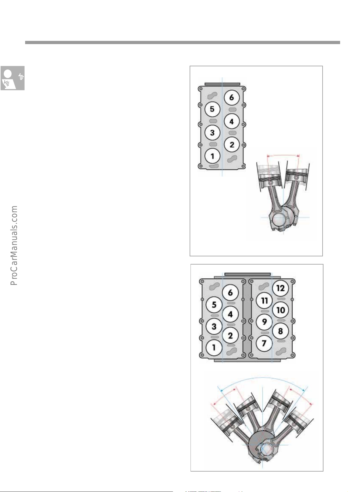
Introduction
VR engines
The need for a powerful alternative suitable for
transverse mounting for use in lower mid-range
vehicles saw the development of the VR engine.
Six cylinders, offset at a V-angle of 15°, are
accommodated in a fairly slender and very short
engine block. Unlike previous designs, the
engine only has one cylinder head. This made it
possible to supply the Golf with a compact VR6
cylinder engine, for example.
15
S248_007
W engines
The engines of the W family are a combination
of two "VR banks" based on a modular design
principle.
The cylinders of one bank have an angle of 15°
relative to each other while the two VR banks are
arranged at a V-angle of 72°.
S248_009
15
S248_008
72°
S248_010
6
Page 7
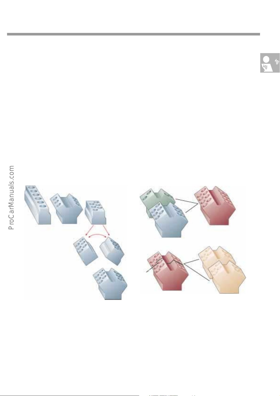
The modular design principle of the W engines
Numerous components of the VR and W series
Proven, serial-produced components from the
modules of the VR engine family were integrated
into the new W engine concept. The principle is
very simple.
Two compact VR engines from the VR series are
combined to produce a W engine. The result is a
series of compact petrol engines ranging from
the W8 to the W16.
are identical, e.g.:
- valves, valve springs and valve seat inserts
- roller rocker fingers
- valve clearance compensating elements
This allows us to manufacture many parts in
series and achieve high volumes.
6 cylinder
V engine
6 cylinder
inline engine
2xVR6
6 cylinder
VR engine
72°
W12
S248_105
With regard to the evolution of the 6-cylinder
engine, the VR6 engine stands out due to its
compactness. It is much shorter than the
comparable inline engine, and narrower than
the V engine. Combining two VR6 engines with a
cylinder angle of 72° produces a W12 engine.
W16
W12
W16
2xW8
S248_011
A W16 engine is obtained by joining two
cylinders to each cylinder bank of a W12 engine.
Splitting the W16 in the middle leaves two
W8 engines. A W10 engine consisting of two
VR5 engines is also a possibility. This covers the
complete range of W engines.
7
Page 8
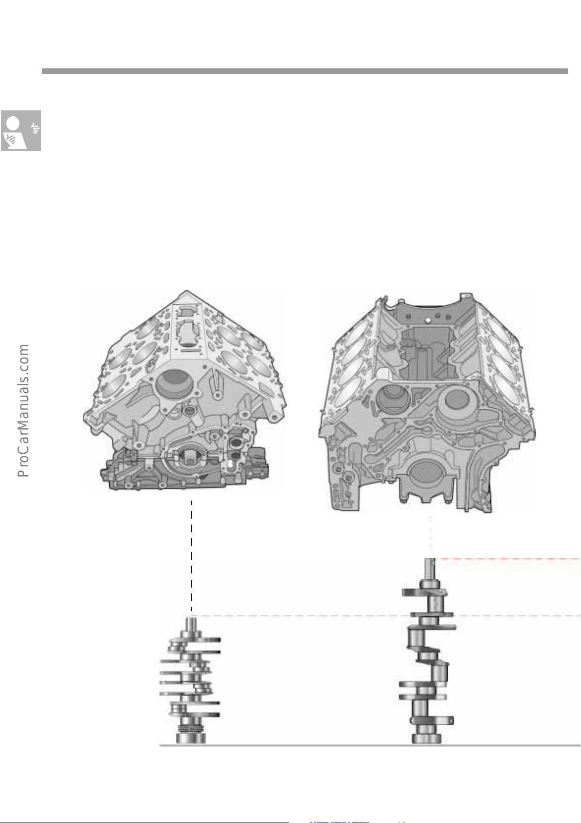
Introduction
A comparison
When a conventional 8-cylinder V engine
(comparable displacement) is compared to an 8cylinder W engine, the latter particularly stands
out due to its compact design and very small
external dimensions.
The W8 engine
This is also reflected in a comparison of the
crankshafts. The compact design of the 12cylinder
W engine is highlighted by the fact that it has
even smaller external dimensions than a
conventional V8 engine.
The V8 engine
S248_014
S248_012
W8 crankshaft V8 crankshaft
8
Page 9
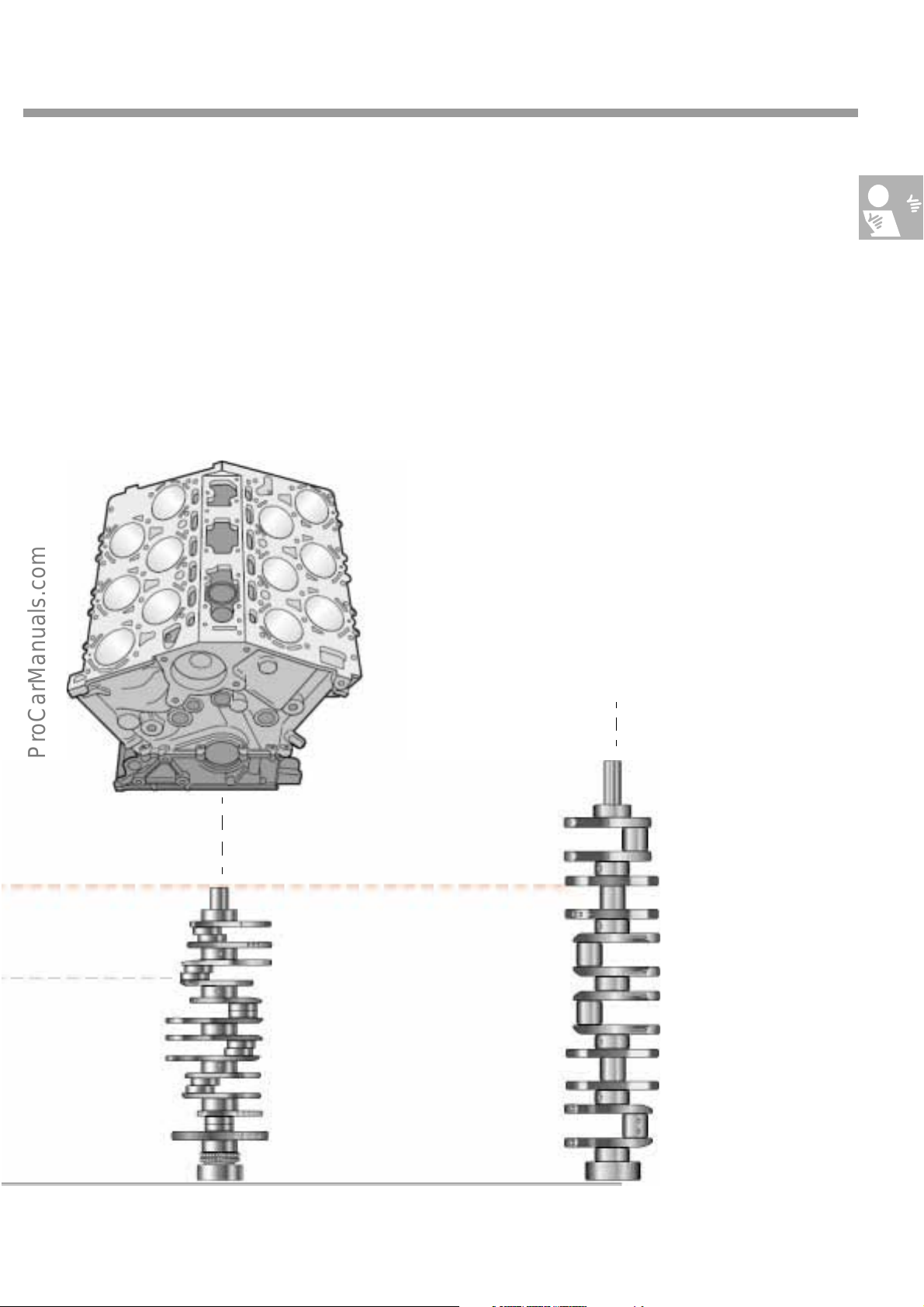
Comparing the 12-cylinder crankshaft of a
conventional V12 engine with that of a 12cylinder W engine emphasises the constructional
advantage.
The W12 engine
Depending on the number of cylinders, the W
principle therefore saves material, and hence
also weight.
The crankshaft of a V12 engine with the most
available space is shown by way of comparison
W12 crankshaft
S248_013
S248_150
V12 crankshaft
9
Page 10
Engine mechanicals
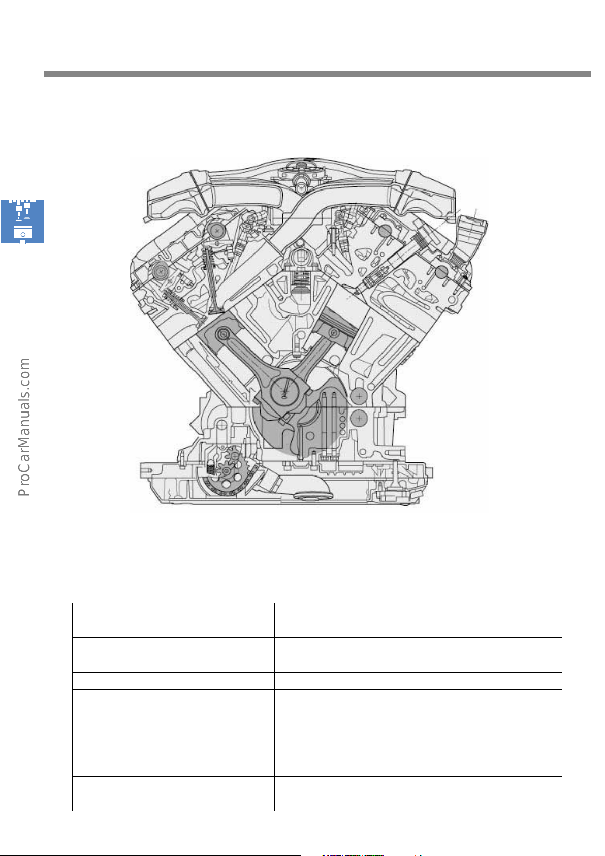
Specifications - the W8 engine
Displacement [cc] 3999
Bore [mm] 84
Stroke [mm] 90.168
Number of cylinders 8
Number of cylinder heads 2
Offset [mm] ± 12.5
Bank offset [mm] 13
V-angle of cylinder heads [°] of both banks 72°
V-angle of cylinders [°] in a bank 15
Number of valves 4 / cylinder
Splitpin (crankshaft journal offset) -18°
S248_017
10
Firing order 1-5-4-8-6-3-7-2
Page 11
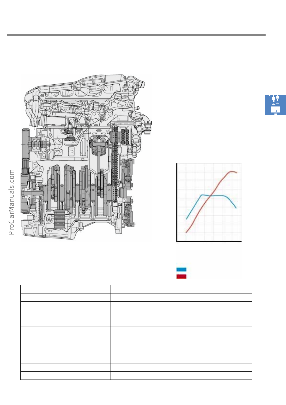
Torque and power output
[Nm]
[kW]
Engine code BDN
Dimensions (l x w x h) [mm] 420 x 710 x 683
Weight [kg] approx. 193
S248_018
500
400
300
200
100
200
150
100
50
2000 4000 6000
rpm
S248_021
Torque curve
Output curve
Max. output [kW] ([bhp]) 202 (275)
Max. torque [Nm] 370
Fuel 98 RON to DIN EN 228
The engine may also be operated alternatively with 95 RON
unleaded premium fuel with a slight reduction in performance and
torque.
Engine management system Bosch Motronic ME7.1
Installation position in-line
Allocated gearbox 5HP19 4-Motion, C90 6-speed 4Motion
11
Page 12
Engine mechanicals
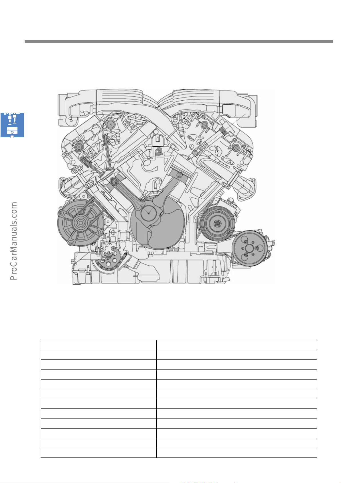
Specifications - the W12 engine
Displacement [cm3]5998
Bore [mm] 84
Stroke [mm] 90.168
Number of cylinders 12
Number of cylinder heads 2
Offset [mm] ± 12.5
Bank offset [mm] 13
V-angle of cylinder heads [°] of both banks 72°
V-angle of cylinders [°] in a bank 15
Number of valves 4 / cylinder
Splitpin (crankshaft journal offset) +12°
S248_019
12
Firing order 1-12-5-8-3-10-6-7-2-11-4-9
Page 13
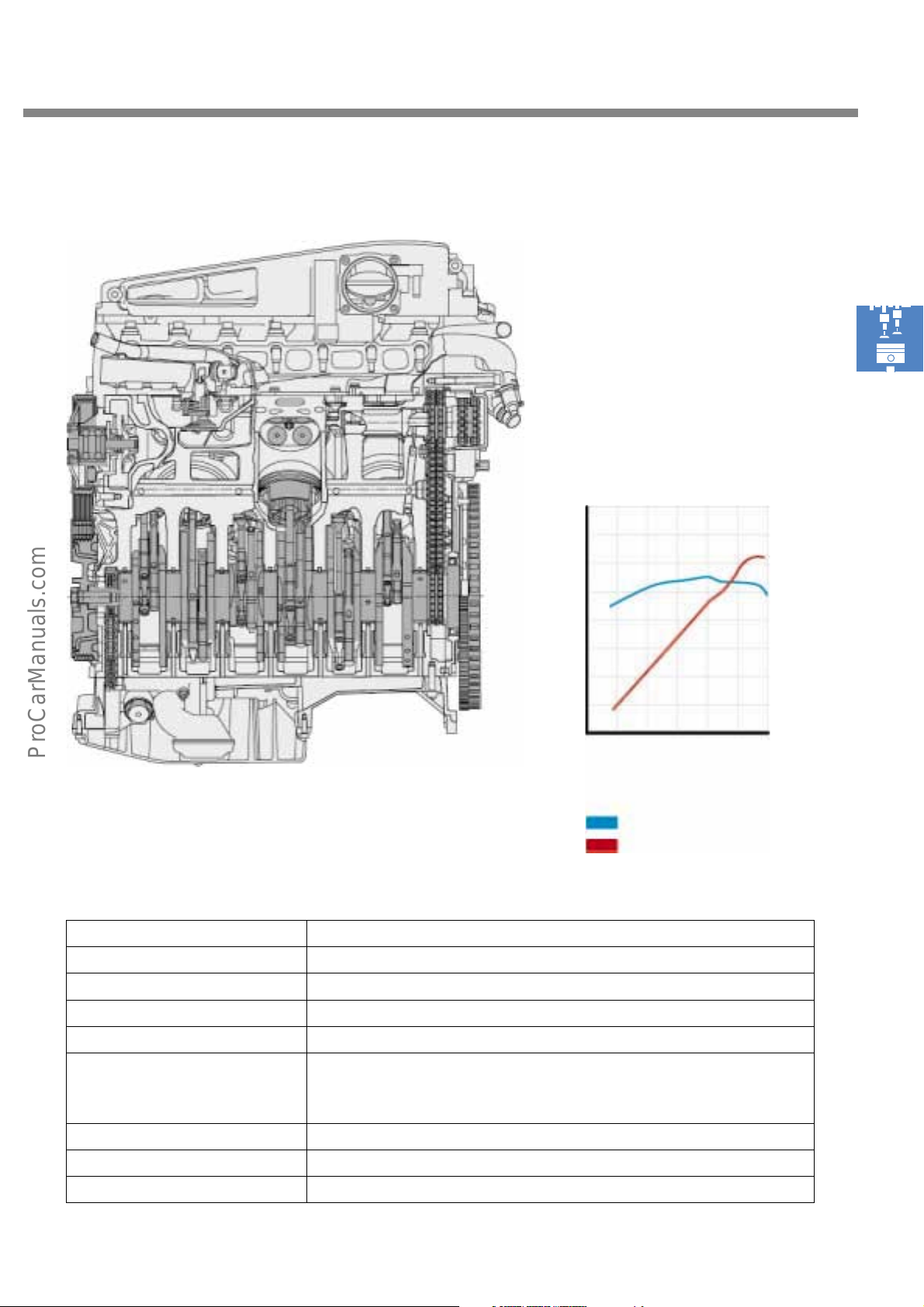
Torque and power output
Engine code BAN
S248_020
[Nm]
800
700
600
500
400
300
200
100
2000 4000
Torque curve
Output curve
[kW]
400
350
300
250
200
150
100
50
6000
rpm
S248_022
Dimensions (l x w x h) [mm] 513 x 710 x 715
Weight [kg] approx. 245
Max. output [kW] ([bhp]) 309 (420)
Max. torque [Nm] 550
Fuel 98 RON to DIN EN 228
The engine may also be operated alternatively with 95 RON unleaded
premium fuel with a slight reduction in performance and torque.
Engine management system Bosch Motronic ME7.1.1 (dual control unit concept)
Installation position in-line
Allocated gearbox 5HP24 4Motion
13
Page 14
Engine mechanicals
The crankshaft drive
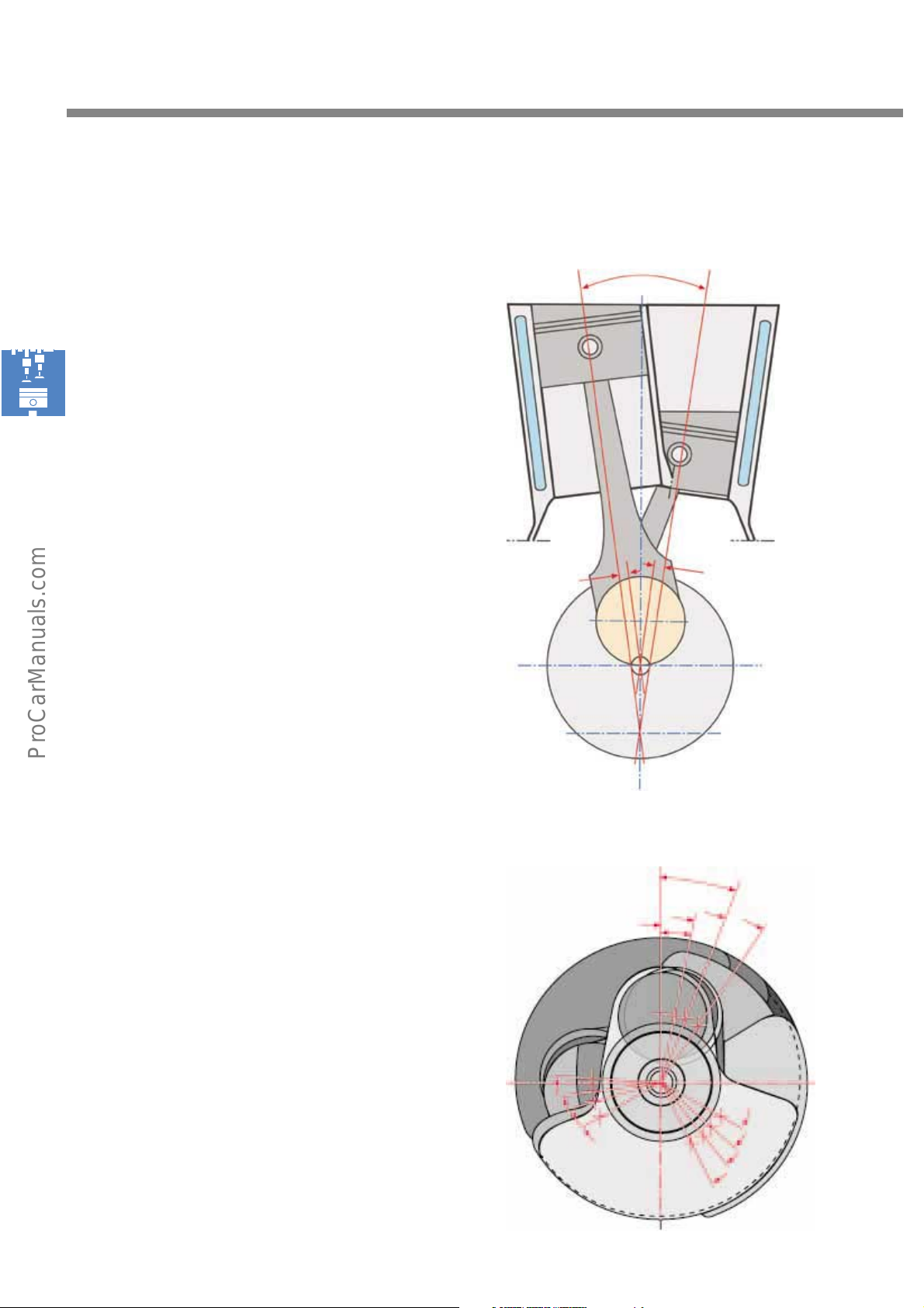
The offset
The cylinders of a bank are offset in a tandem
arrangement and positioned at a very narrow
angle of 15°.
The compact W engine was made possible by
arranging two banks at an angle of 72°.
To provide adequate space for the pistons in the
bottom dead centre range, it was necessary to
offset the crankshaft drive. This means that the
cylinders are offset by 12.5 mm outwards relative
to the centre of the engine (crankshaft fulcrum).
Centre of cylinder
15
Centre of cylinder
The crank pin offset
A constant spark gap is maintained by the crank
pin offset, or what is known as the 'splitpin'.
The layout of the W engine is based on a 10-
cylinder engine. All cylinders in a 4-stroke engine
fire within a crank angle of 720°.
W10 engine
720° crankshaft : 10 cylinder = 72° bank angle
W8 engine
720° : 8-cylinder = 90° spark gap
72° bank angle - 90° spark gap =
Splitpin -18°
W12 engine
720° : 12 cylinder = 60° spark gap
72° bank angle - 60° spark gap =
Splitpin +12°
Offset
12.5 mm left
S248_186
W12 engine
21.833°
7
1
12°
Offset
12.5 mm right
Middle of cranks-
haft
Point of intersection of
centres of cylinders
6
12
14
8
2
11
5
3
9
4
10
S248_026
Page 15
The engine in detail
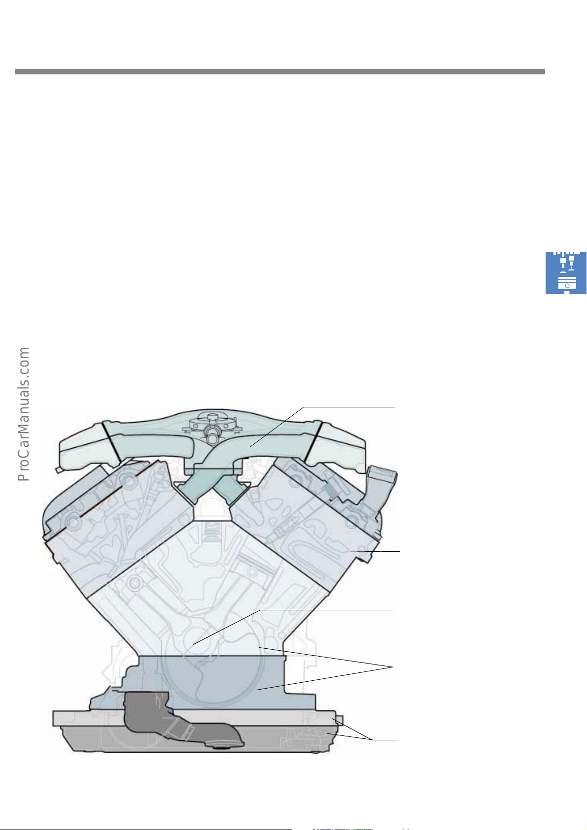
To familiarise you thoroughly with the mechanical construction of the W8 and W12 engines, we will
now describe the main modules of both engines in succession.
The following topics will be dealt with:
- the crankcase with bearing support,
- the crankshaft with conrods and pistons,
- the balancing shafts,
- the cylinder heads,
- the oil sump and oil pump,
- the crankshaft drive,
- the timing chain drive,
- the belt drive for auxiliary components and
- the multi-part intake manifold
W8 engine
the multi-part intake manifold
the cylinder heads
the crankshaft with
conrods and pistons
the crankcase with
bearing support
S248_025
the split oil sump
with oil pump.
15
Page 16
Engine mechanicals
The crankcase
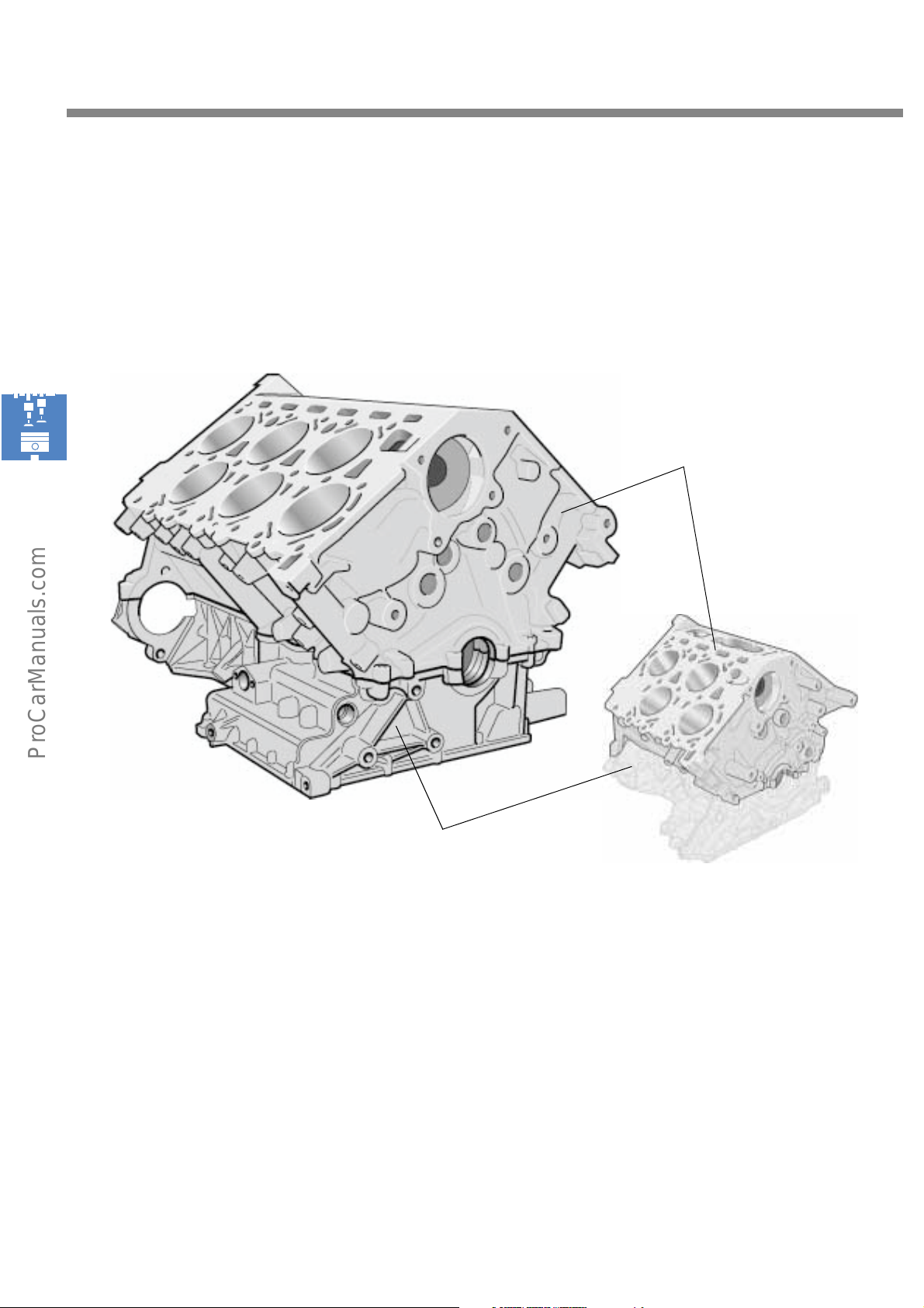
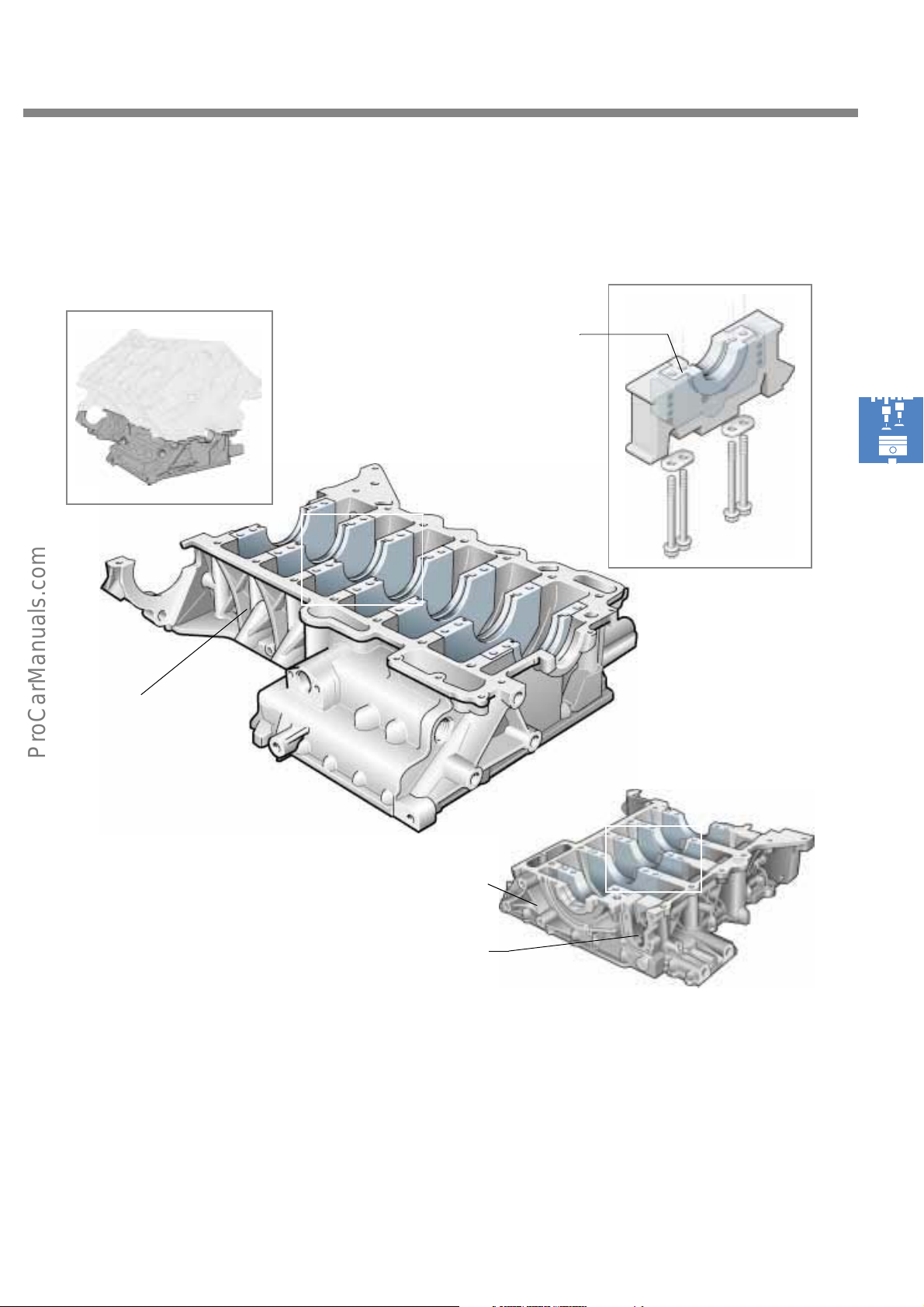
The crankcase comprises two components: the crankcase upper section and the crankcase lower section.
The upper section contains, among other things, the cylinders and the upper bearing cover halves of the
crankshaft. The crankcase lower section is designed as a bearing support and carries the lower bearing
cover halves.
W12
Crankcase upper section
S248_028
The crankcase upper section
The "aluminium" crankcase upper section is
made of a hypereutectic aluminium-silicon alloy
(AlSi17CuMg).
Hypereutectic means that pure silicon crystals
initially precipitate out of the aluminium-silicon
melt while it cools before aluminium/silicon
crystals form. Due to the presence of these silicon
crystals within the metal microstructure, the
cooled melt is harder than a eutectic Al-Si alloy.
Crankcase lower section
Use of this alloy eliminates the need for
additional cylinder liners or a plasma coating for
the purposes of cooling and lubricating the
cylinder surfaces as the material already has
sufficient natural strength and thermal stability.
W8
S248_027
16
Page 17
The crankcase lower section
The crankcase lower section is a bearing support with integral bearing seats
Bearing cover
S248_033
S248_030
Cast element in
bearing support
W12 bearing support
S248_032
Casing opening towards drive
The bearing support is also made of aluminium.
It serves as a frame structure for the lower
crankshaft bearing covers. These bearing covers
are made of grey cast iron and are also
embedded when the bearing support is cast.
W8 bearing support
of balancing shafts
S248_029
They are located on the pressure side of the
crankshaft and give the crankshaft bearing the
strength it requires.
The bearing support is attached to the crankcase
upper section by 4 bolts per bearing cover.
17
Page 18
Engine mechanicals
The crankshaft
Journals for driving the oil pump
and the balancing shaft
W8 crankshaft
S248_036
Main bearing Conrod journal
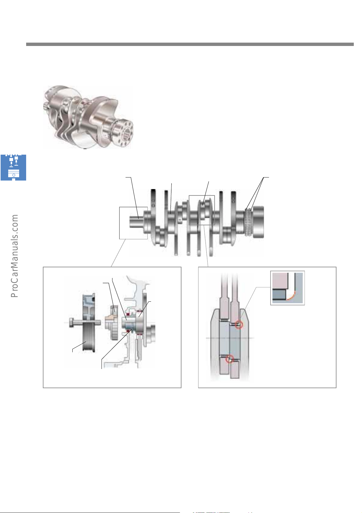
The crankshafts used in the W engines are
manufactured from forged tempered steel.
In each case, two conrods run between two main
bearings.
Gears for the double-
chains of the chain drive
S248_037
Toothed belt pulley
Balancing shafts
Vibration absorber
Gear
Oil pump
The drive gear of the oil pump, together with the
toothed belt pulley for the balancing shafts (on
the W8 engine only), is pressed against the outer
main bearing and fixed in place by the vibration
absorber.
Crankshaft journal
Main
bearing
S248_056
S248_043
Crankshaft of the
W engine family
with corner radii
S248_045
The conrod journals are arranged in pairs and in
accordance with the crankshaft throw.
When the conrods are installed, the bearing
cups must not contact the radii or the edge
between the two conrod faces (use tool).
18
Page 19
Conrods and pistons
Trapezoidal shape
S248_048
Bores
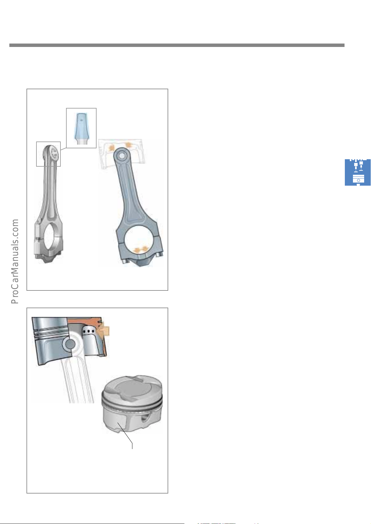
The conrods are made of forged steel and are
only 13 mm thick. They are of a trapezoidal
construction and are cut during the production
process.
To ensure better oil exchange, two grooves are
milled in the side faces of the conrod lower
sections. The conrod pin is lubricated through
two inclined bores in the conrod head.
S248_047
S248_016
S248_049
S248_050
Grooves for oil exchange
Drainage
holes
The pistons are made of an aluminium-silicon (Al
Si) alloy. The recess in the piston surface is very
shallow as the cylinder head takes up most of the
combustion chamber volume. The inclined piston
surface is necessary because of the V-position
adopted by the pistons.
Each piston carries 2 piston rings and an oil
taper ring. To drain off the oil which collects in
the scraper ring, small drainage holes lead into
the piston ring groove towards the inside of the
piston
Iron (Fe) coating
for Al Si liners
in central crankcase
19
Page 20
Engine mechanicals
The balancing shaft of the W8 engine
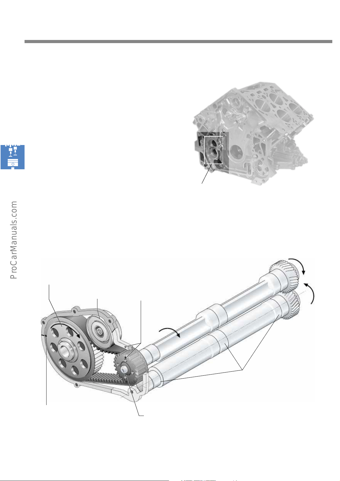
The W8 engine has two balancing shafts for
compensating the forces of inertia. The two shafts
are housed in the crankcase. The upper
balancing shaft is driven by the crankshaft by
means of a toothed belt. A gear located at the
end of the upper balancing shaft drives the
lower balancing shaft.
The balancing shafts are mounted in two location
holes on the clutch side of the crankcase.
Drive gear
on the crankshaft
Tension pulley
Installation
openings
Align marker on
balancing shaft drive gear
with the marker on the sealing face
(TDC of 1st cylinder).
S248_055
S248_057
20
Align marker on crankshaft drive
gear with the joint (TDC of 1st
cylinder).
Bearing in bearing bushes
of the crankcase
Drive gear
on the balancing shaft
Page 21
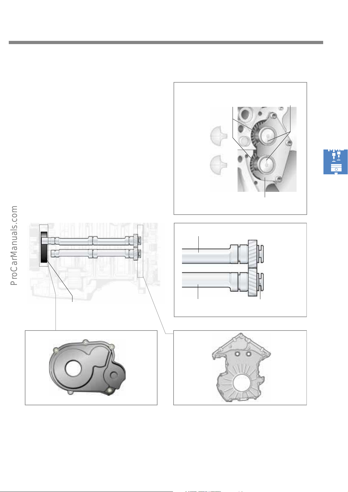
There is a groove at the gear wheel end of the
balancing shaft. The lock plate engages into this
groove, locating the balancing shafts axially.
During installation, the balancing shafts must be
aligned with regard to the TDC position of the 1st
cylinder.
The balancing shafts must be rotated so that the
markings on the balancing shafts are opposite
each other.
Gears of the
balancing shafts
Position of balancing
shafts at TDC of 1st
cylinder
Balancing shaft I
Marking
S248_108
Lock plate
S248_054
The balancing shaft drive is protected on the belt
drive side by a plastic housing cover.
Drive
S248_058
S248_107
Balancing shaft II
Locking grooves
S248_059
On the clutch side, the openings for inserting the
balancing shafts, together with the chain drive,
are sealed by an aluminium cover.
21
Page 22
Engine mechanicals
Two-mass flywheel with clutch
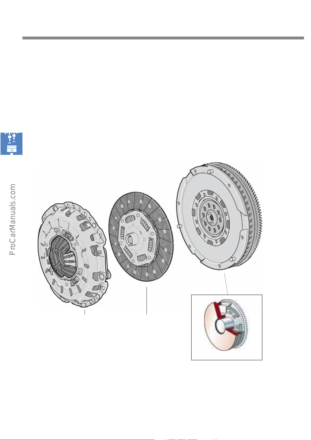
W engines fitted with a manual gearbox generally have a two-mass flywheel.
This flywheel prevents torsional vibration from being transmitted by the crankshaft to the gearbox via the
flywheel. This would otherwise adversely affect handling performance.
Clutch cover Clutch disc
S248_060
Two-mass flywheel
S248_061
22
Page 23
S248_061
T
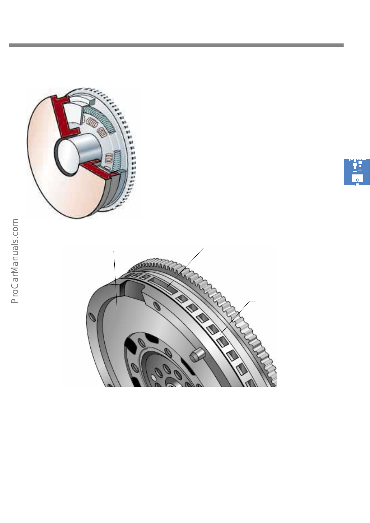
A spring damper system within the two-mass
flywheel separates the primary inertia mass from
the secondary inertia mass so that the torsional
vibration produced by the engine is not
transmitted to the gearbox.
On W engines with automatic transmission, the
two-mass flywheel is substituted by a converter
plate.
Two-mass flywheel
ooth gap
Pulse sensor wheel
S248_062
The two-mass flywheel also serves as a sender wheel. Its job is to determine the engine speed and
recognise cylinder No. 1 together with the Hall senders of the camshafts. It has a larger tooth gap which
serves as a marker point. This point is registered by the engine speed sender located in the gearbox
housing during each revolution of the two-mass flywheel.
23
Page 24
Engine mechanicals
The cylinder heads
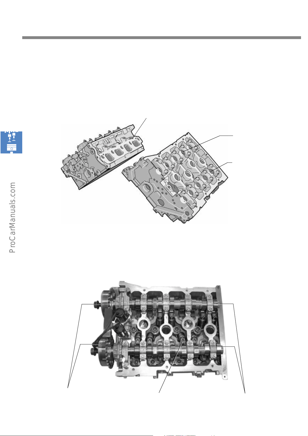
The W engines have two aluminium cylinder heads with two overhead camshafts apiece.
The injectors are inserted into the cylinder heads.
Cylinder heads of W8 engine
Each of the cylinder heads in the two W engines has an intake camshaft and an exhaust camshaft with
camshaft adjusters attached to their end faces.
Opening for injector
Camshaft bearing - intake
Camshaft bearing -
exhaust
S248_063
24
Camshaft adjuster
S248_067
CamshaftsRoller rocker finger
Page 25
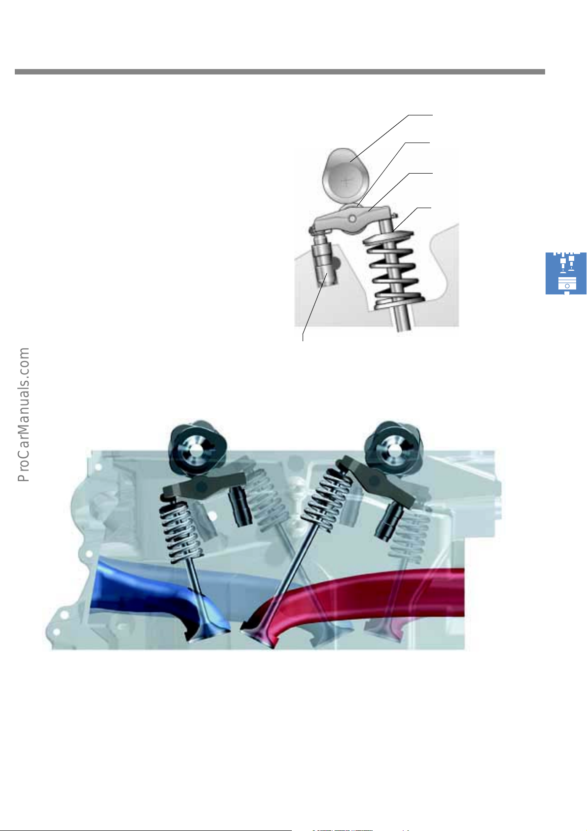
Camshaft
The 4 valves in each cylinder are actuated by
low-friction roller rocker fingers. Valve clearance
is compensated by hydraulic support elements.
Cam roller
Roller rocker finger
Val ve
S248_160
Hydraulic support element
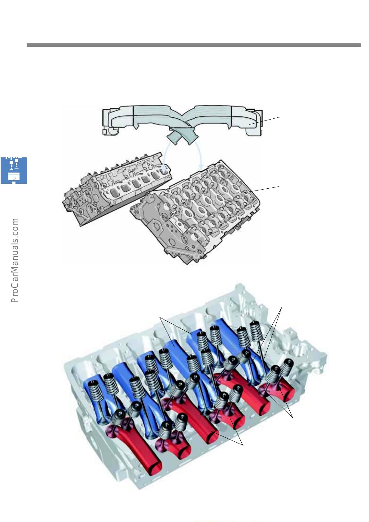
Due to the cylinder arrangement, short and long
valves as well as short and long inlet and
exhaust ports alternate with one another.
S248_161
25
Page 26
Engine mechanicals
Intake manifold of W12
engine
Air supply intake
Cylinder heads of W12
engine
S248_170
Intake valve
Intake ports
S248_171
Exhaust valve
26
Exhaust ports
Page 27
The secondary air ducting system
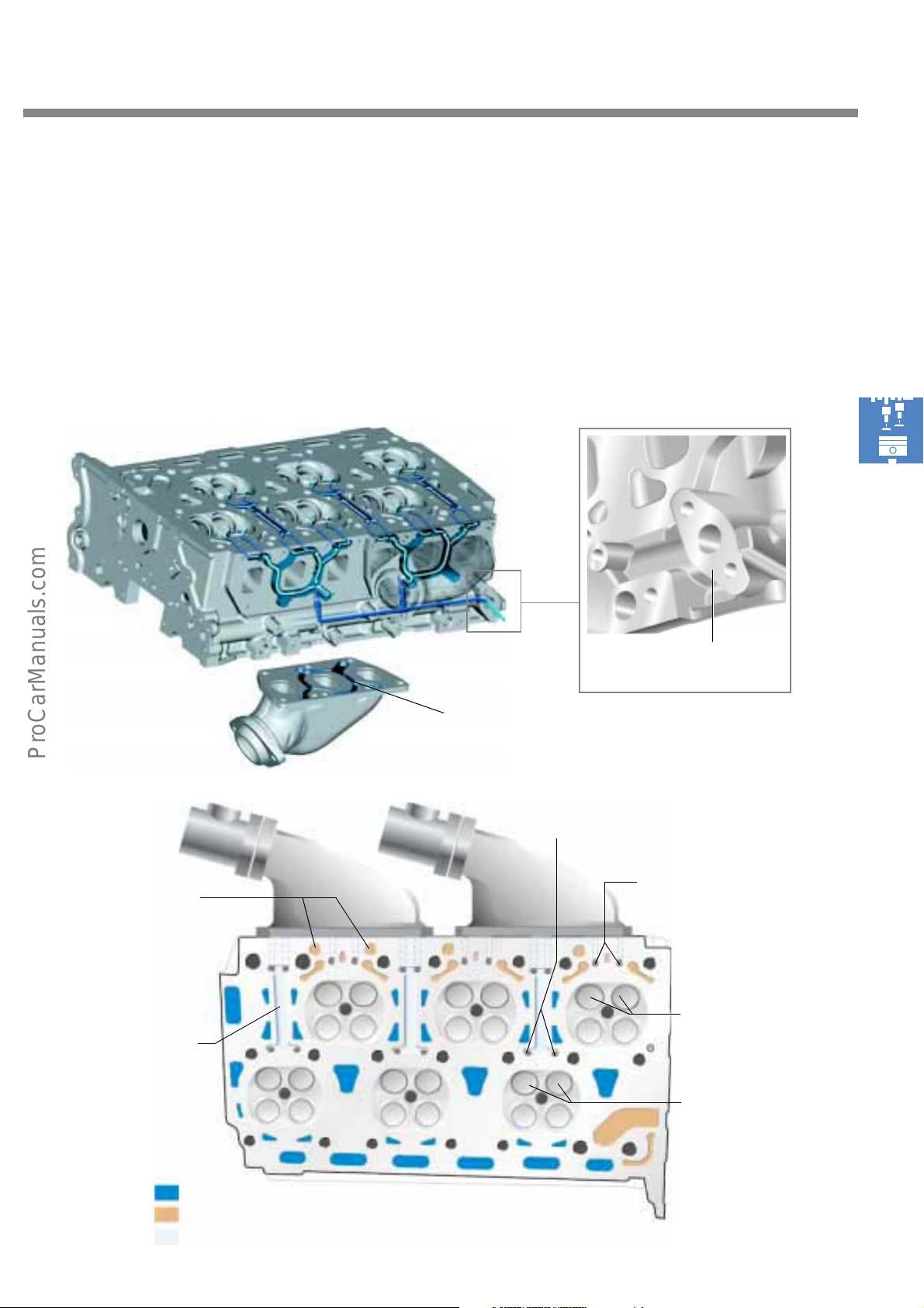
Beside the coolant and oil ducts, the secondary
air is guided via ducts and bores into the exhaust
ducts near the exhaust valves. The secondary air
flows into a duct in the cylinder head via a
secondary air inlet valve.
From here the secondary air is guided back into
the cylinder head via grooves in the exhaust
flange. The secondary air then flows via ducts
and bores to the exhaust valves.
S248_169
S248_172
Connection for secondary air
inlet valve
Oil return
holes
Secondary air duct
Groove in exhaust flange
Bores leading to exhaust
valve (internal)
Bores leading to exhaust
valve (external)
Exhaust valves
(external)
Exhaust valves
(internal)
Coolant
Oil ducts
Secondary air
S248_174
27
Page 28
Engine mechanicals
The chain drive
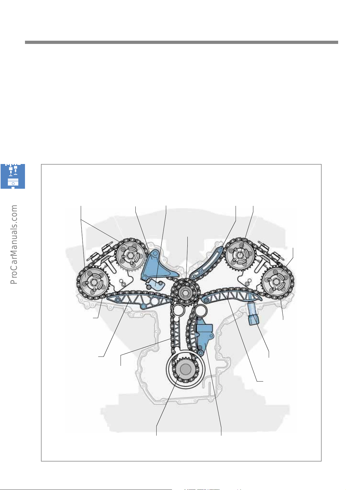
The chain drive is mounted at the flywheel end of the engine. Engine power is transmitted by a gear on
the crankshaft to the gears of the central intermediate shaft by means of a double-chain.
At this point, each of the camshafts of the two cylinder heads is driven by means of a single chain. Three
hydraulic chain tensioners ensure that an optimal chain tension is maintained.
Chain drive of W engines
Camshaft adjuster Chain tensioner
Single chain
(sleeve type chain)
Left bank
Slide rail
Tensioning rail Slide rail
Central intermediate shaft
Double chain
(roller chain)
Inlet camshaft
Exhaust
camshaft
Single chain
(sleeve type chain)
Right bank
Chain tensioner
Tensioning rail
28
Gear on crankshaft
Chain tensioner with
tensioning rail
S248_075
Page 29
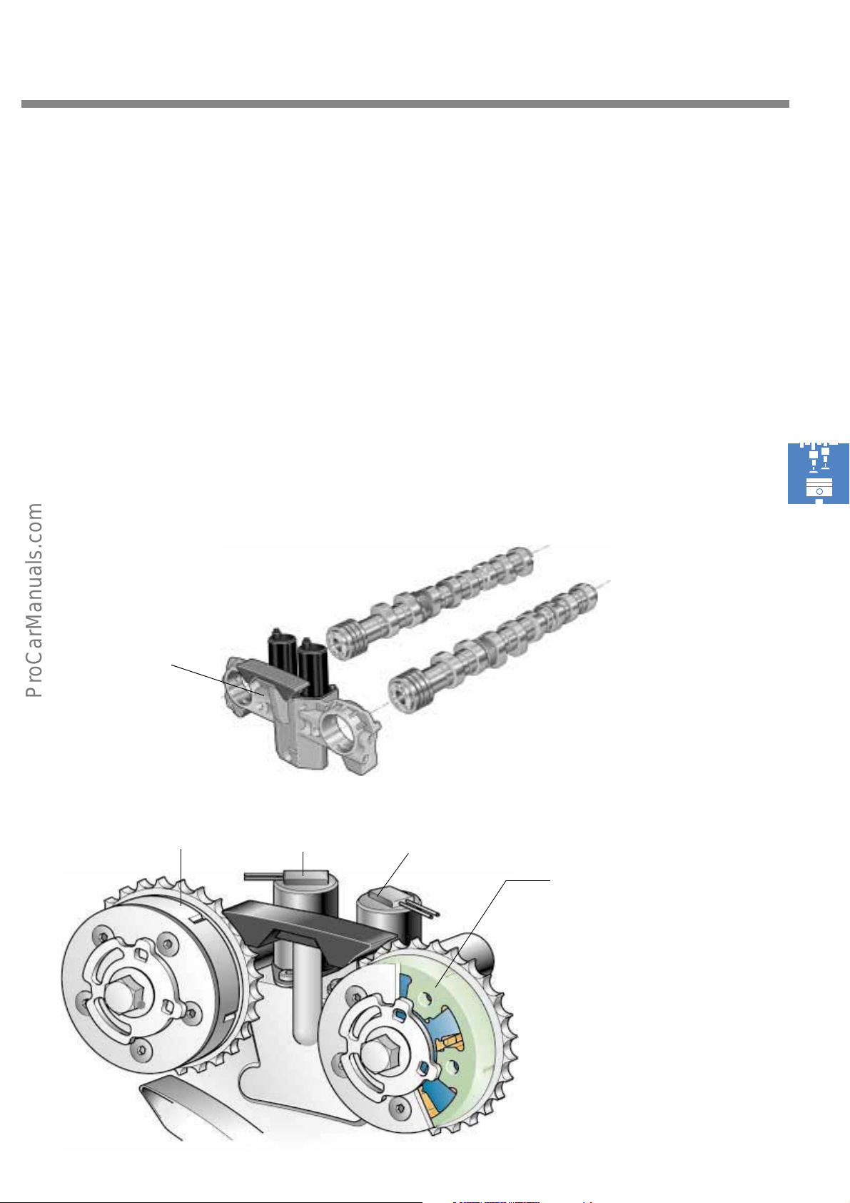
The camshaft timing control
Like the W12 engine, the W8 engine has
continuous camshaft engine timing control.
In this case, "continuous" means that the inlet
camshaft can be advanced/retarded relative to
its neutral position at any angle within a range of
52°.
The camshaft is adjusted by hydraulic
camshaft positioners bolted to the end face of
each camshaft. The exhaust camshaft of the W8
engine is an exception. It can only be adjusted to
the "advance" or "retard" position within a
range of 22°. The engine control unit regulates
the oil supply to the camshaft positioners via the
solenoid valves.
Timing case
Vane a dj ust e r
Inlet camshaft
Solenoid valve
N205
S248_176
Solenoid valve
N318
Vane a dj ust e r
Exhaust camshaft
S248_128
29
Page 30
Engine mechanicals
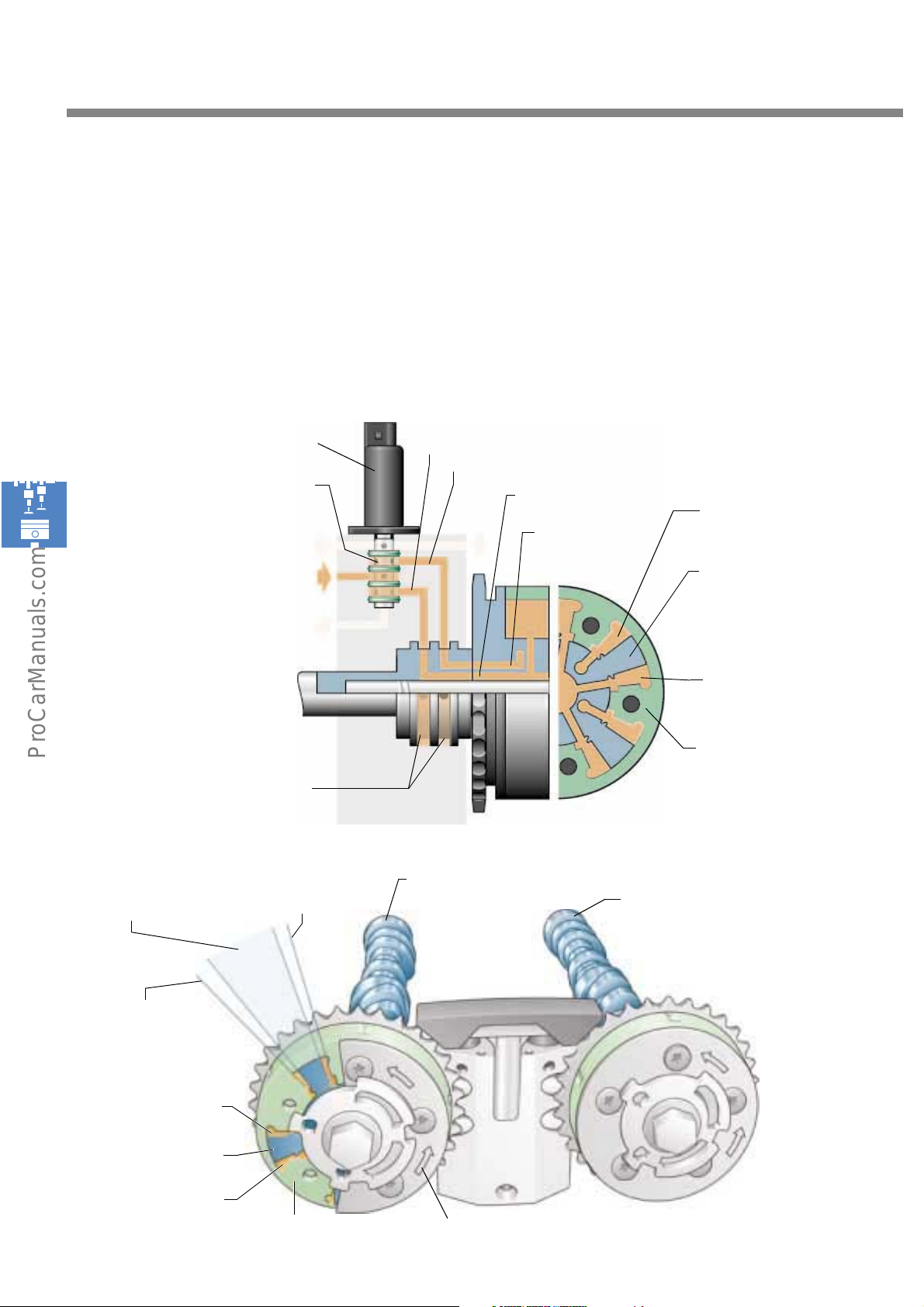
System design
Neutral position
When the solenoid valve moves the adjusting piston into a central position, this causes both oil ducts
(a+b) - and hence the chambers (A+B) on either side of the inner rotor - to fill with oil. The inner rotor,
together with the camshaft which it is rigidly coupled to, now adopts a position in the middle of the
adjustment range.
Solenoid valve
Adjusting piston
Oil return passage
Engine oil pressure
Oil return passage
Annular ducts
Camshaft
neutral
Stop
Retard adjuster
Oil duct (a)
Oil duct (b)
Oil duct (aa)
Chamber (B)
Oil duct (bb)
Inner rotor
(rigidly coupled to
camshaft)
Chamber (A)
Outer rotor
(coupled to timing chain)
S248_135
Inlet camshaft
Exhaust camshaft
30
Stop
Advance adjuster
Chamber (A)
Inner rotor
Chamber (B)
Outer rotor
Bank I
S248_139
Direction of rotation of drive
Page 31
Retard adjustment
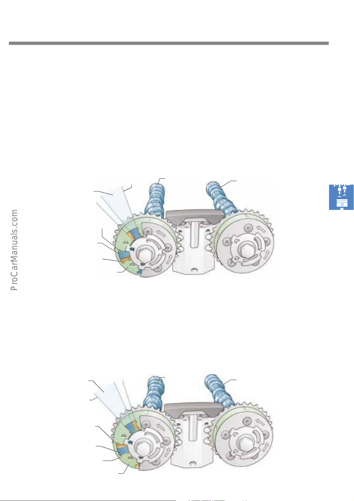
The solenoid valve guides the oil into the oil duct (b). The oil flows from channel (b) through the annular
groove and camshaft and via the bores (bb) to the chambers (B) of the camshaft adjuster. When the oil
enters the chambers (B), the inner rotor is rotated against the direction of rotation of the drive, thus
adjusting the camshaft in the retard direction. The oil is forced out of the chambers (A) through the bores
(aa). It flows back into the cylinder head via the camshaft and duct (a).
Bank I
Camshaft
Chamber (A)
Inner rotor
Chamber (B)
Outer rotor
Advance adjustment
Retard stop
Intake
camshaft
Exhaust
camshaft
S248_138
To rotate the inner rotor forwards, the adjusting piston housed within the solenoid valve adjusts itself so
that the oil duct (a) is put under oil pressure. As a result, the oil flows in the chamber (A), thus advancing
the inner rotor. Chamber B is simultaneously bled via the solenoid valve so as to ensure a quick response.
Bank I
Camshaft
Advance stop
Chamber (A)
Inner rotor
Chamber (B)
Outer rotor
Intake
camshaft
Exhaust
camshaft
S248_137
31
Page 32
Engine mechanicals
The belt drive
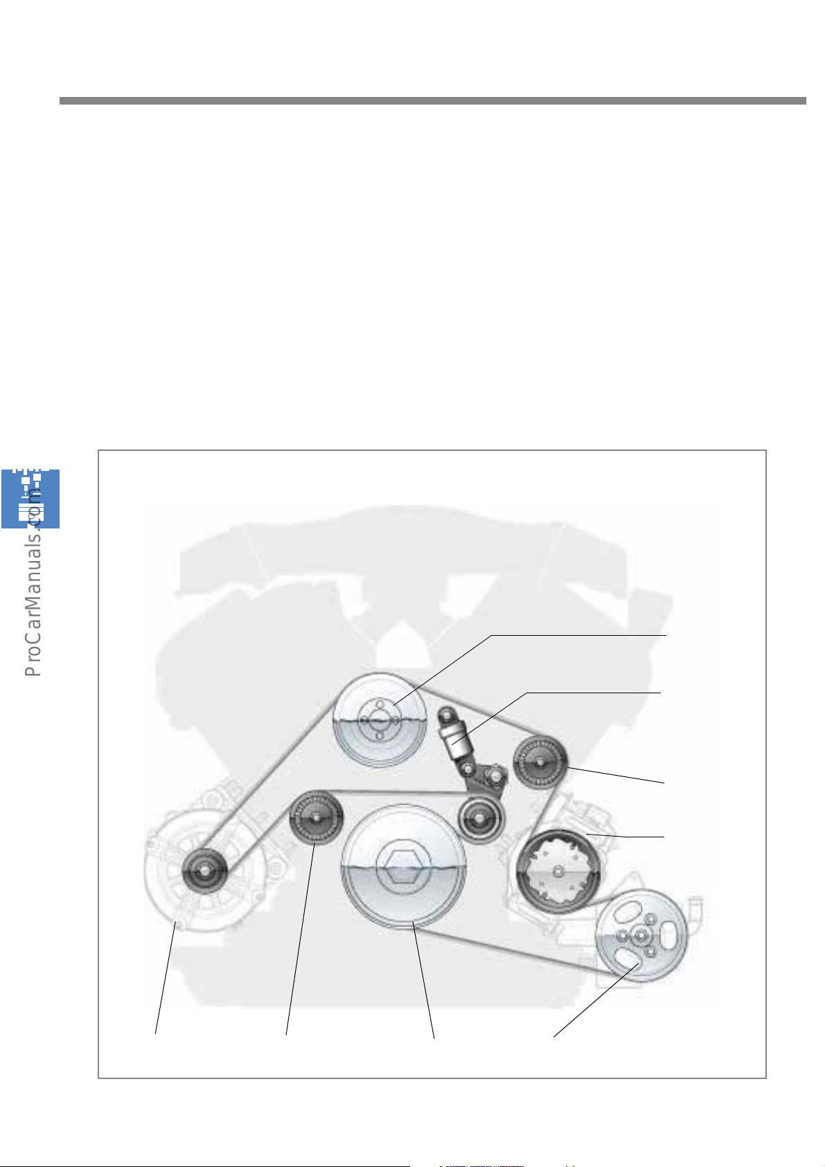
The following units and devices are driven
by the belt drive:
- the coolant pump
- the alternator
- the power steering pump
- the air conditioner compressor
Belt drive of the W8 engine and W12 engine in the VW "D1"
The poly-V-ribbed belt is tensioned by a hydraulic tensioning and deflection pulley. 2 deflection
pulleys ensure that all units to be driven can be
reached.
Wate r p um p
Hydraulic
belt tensioner with
deflection pulley
Deflection pulley
Air conditioner
compressor
32
Alternator
Vibration absorber
Power steering
pump
S248_077Deflection pulley
Page 33
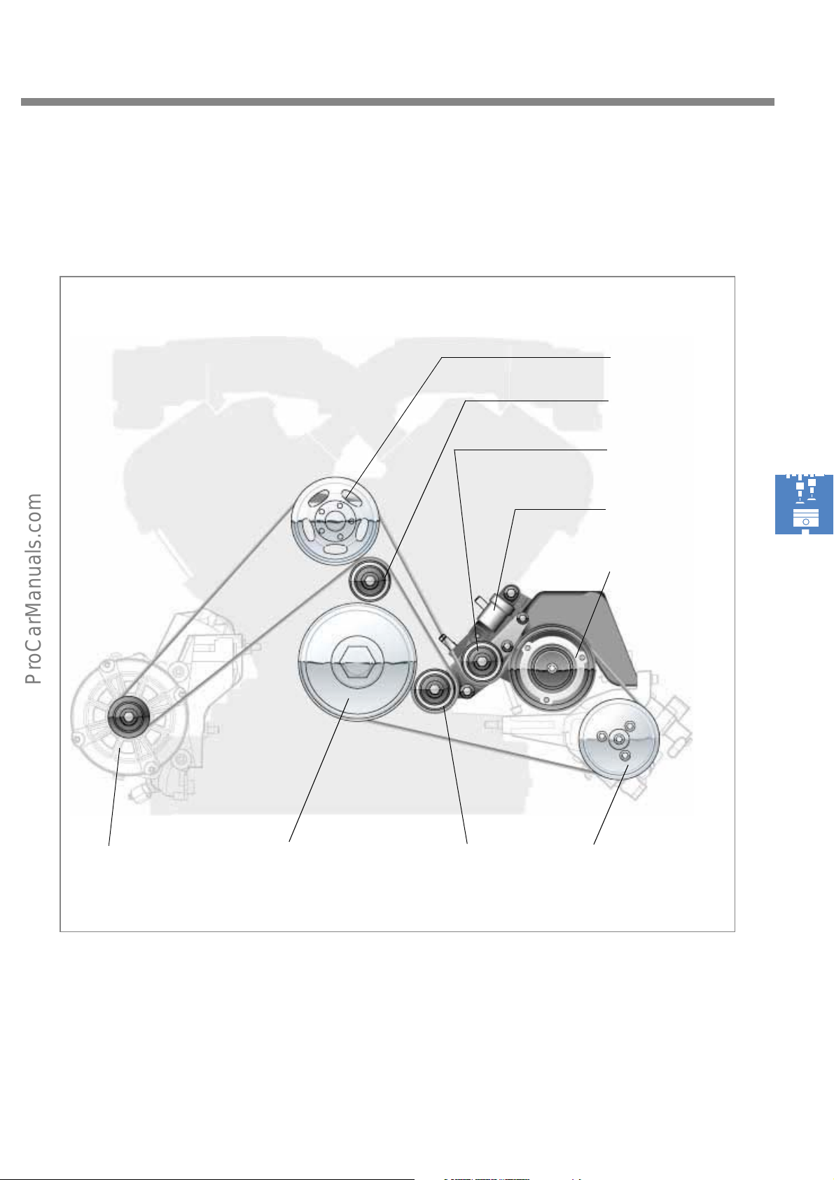
In the W12 engine, the hydraulic belt tensioner and deflection pulley are fixed to the air conditioner
compressor bracket.
Belt drive of the W12 engine in the Audi A8
Coolant pump
Deflection pulley
Deflection pulley
Hydraulic
belt tensioner
Air conditioner
compressor
Alternator
Crankshaft disc with
vibration absorber
Ten s io n pu l ley
Power steering
pump
S248_078
33
Page 34
Engine mechanicals
The oil circuit
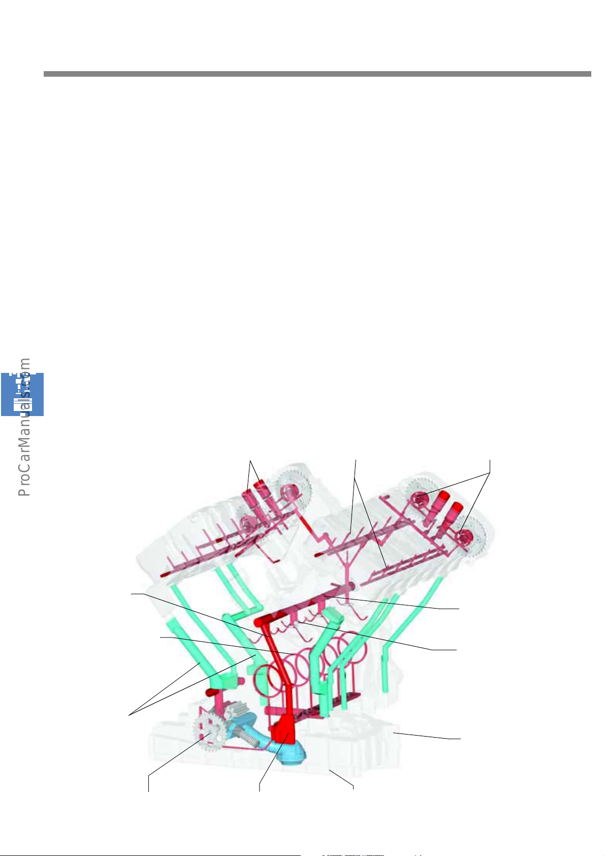
The oil is drawn out of the oil pan by the oil
pump and flows to the central oil passage via the
external
oil filter/cooler module.
The main crankshaft bearings are supplied with
pressurised oil via the central oil passage; the
central oil duct is supplied with pressurised oil via
a riser.
The oil from flows from the central oil duct to the
spray jets for piston cooling, and then from there
to the cylinder heads via risers fitted with nonreturn restrictors.
Oil circuit of the W12 engine
Solenoid valve
Camshaft timing control
The oil also flows to the intermediate shaft, to the
entire engine timing gear and to the chain
tensioner.
In the cylinder heads, the oil flows along ducts to
the camshaft adjusters and the camshaft
bearings.
The return lines guide the oil back into the oil
sump.
Hydraulic elements
Camshaft bearing
Camshaft adjuster
Riser
Crankshaft bearing
Return ducts
Central oil duct
Spray jets for
piston cooling
Oil sump upper section
S248_091
34
Oil pump drive gear Central oil passage
Oil sump lower section
Page 35
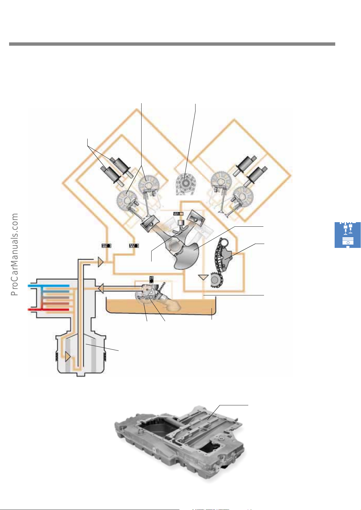
Schematic diagram of the oil circuit of the W engines
Solenoid valve
Camshaft adjuster
Spray jet
Intermediate shaft
Timing belt gear
3 chain tensioners
with chain oil spray
Chain
Oil filter/cooler module
Oil pump
Oil sump of the W8 engine
Return line
S248_094
Oil sump
Central oil passage
S248_083
35
Page 36
Engine mechanicals
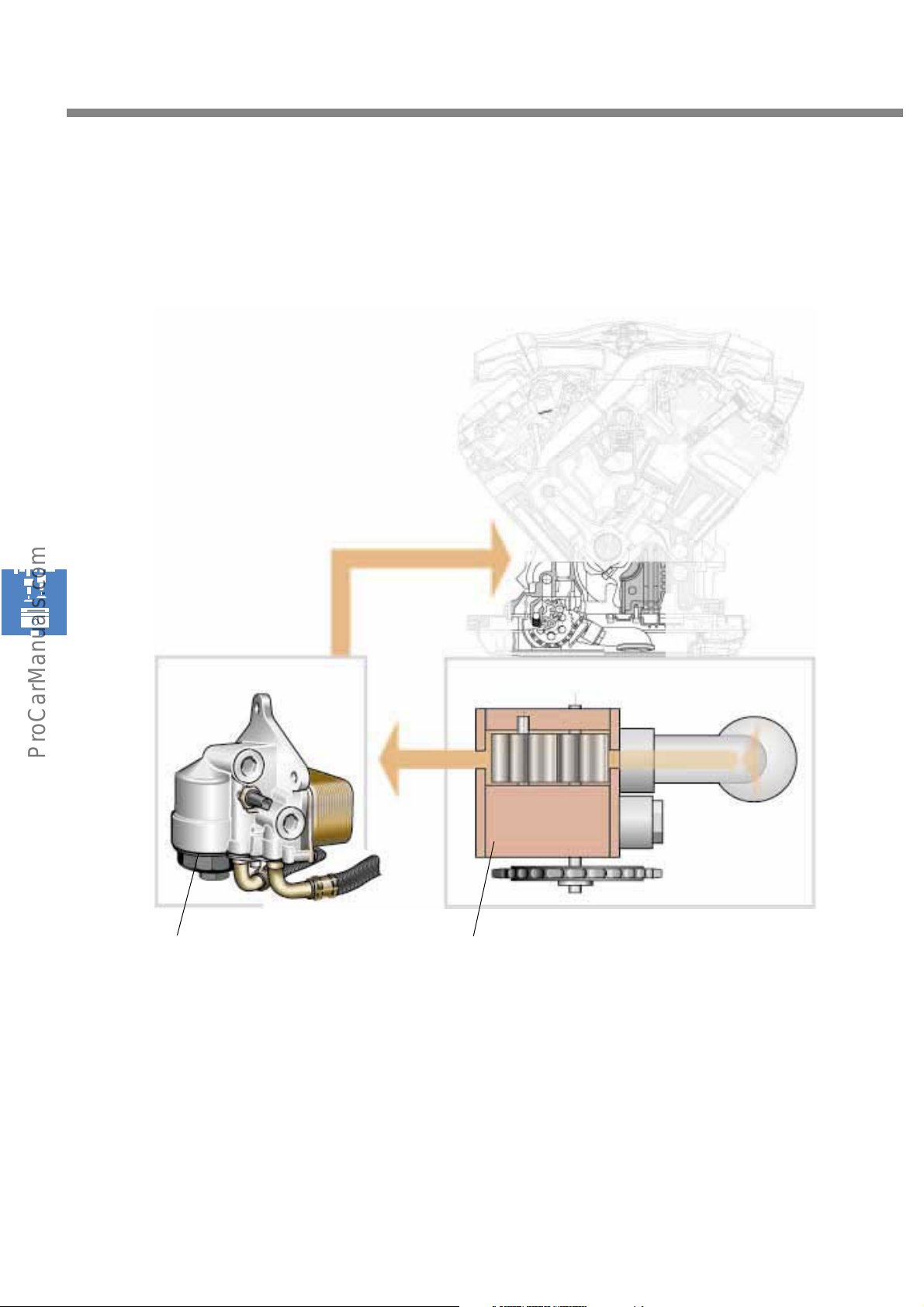
The oil circuit based on the wet-sump principle
The W8 and W12 engine for VW models have a wet-sump lubrication system. The W12 engine for Audi
models has a dry-sump lubrication system.
Wet-sump lubrication system of the W8 engine
Oil filter and cooler module
In the case of the wet-sump lubrication system,
the entire oil supply is retained in the oil sump.
The single-stage oil pump draws the oil out of the
wet sump via the intake line and immediately
returns it to the engine after it has cooled down
and has been filtered.
S248_084
Single-stage oil pump
In contrast to the dry-sump, the job of the oil
sump with wet sump is to retain the entire oil
supply. As a result, it has a larger volume which
affects the overall height of the engine.
36
Page 37
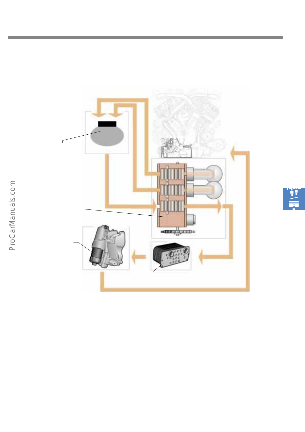
The oil circuit based on the dry-sump principle
Dry-sump lubrication system of the W12 engine in the
Audi A8
Reservoir
Three-stage oil
pump
Filter
S248_088
In the case of the dry-sump lubrication system,
the entire oil supply is retained in an additional,
external reservoir, and not in the oil sump.
To facilitate this, the oil pump is of three-stage
design. Two stages draw the oil out of the oil
sump at various points and pump it into the
reservoir.
Cooler
The third stage (discharge stage) returns the oil
from the reservoir to the engine via the oil cooler
and the oil filter. The oil sump can be kept small
and flat due to its lower oil volume, with the
result that the engine has a smaller overall
height.
This requires a slightly more complex design.
37
Page 38
Engine mechanicals
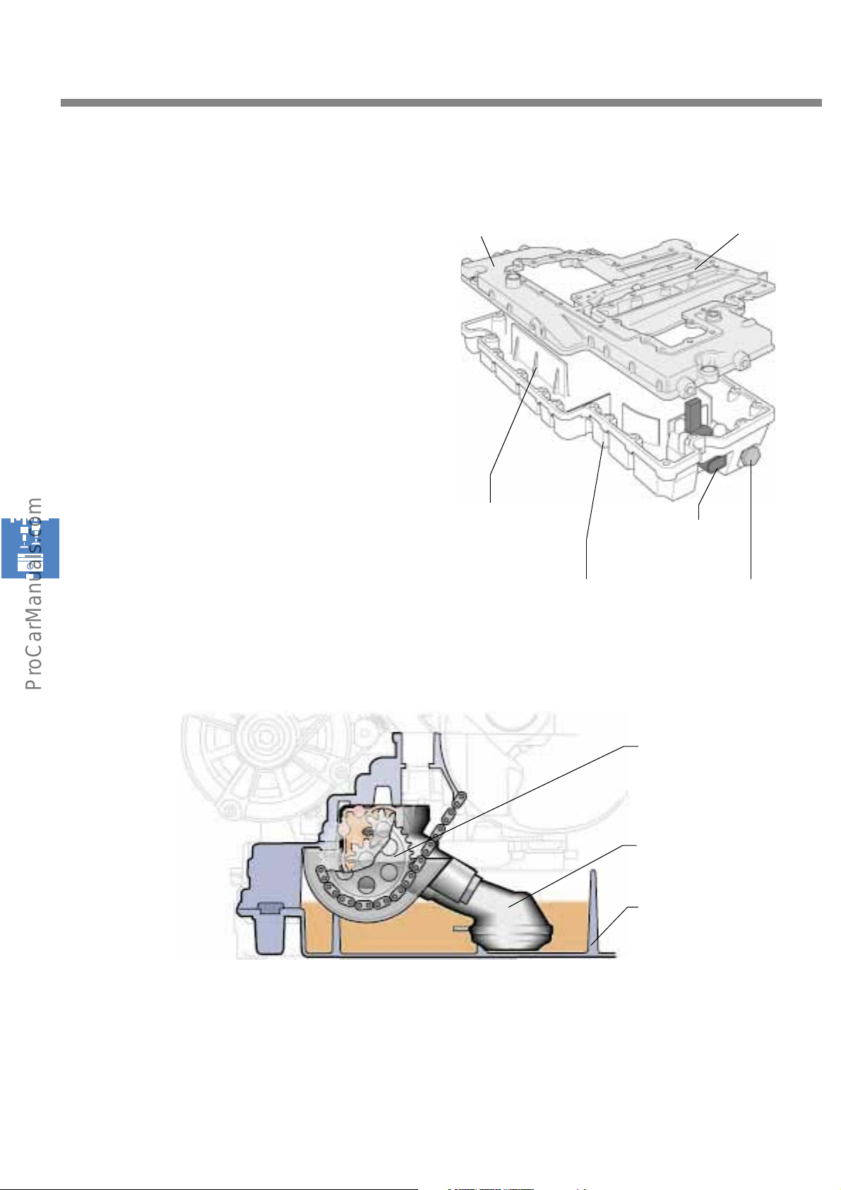
The oil sump
The oil sump comprises two diecast aluminium
parts. The oil sump lower section forms the oil
sump. The central oil passage is accommodated
in the upper section of the oil sump.
Special baffles settle the oil in the oil sump.
The sender which informs the engine control unit
of the oil level is inserted into the oil sump lower
section from below near the oil drain screw, and
then bolted.
Oil sump upper section
S248_079
Central oil passage
The oil pump
Baffles
(swash plates)
Oil level sender
Oil drain screwOil sump lower section
Drive
Intake line
Oil sump lower section
38
S248_082
The oil is extracted from the sump by the oil
pump via the intake line, and pumped into the oil
circuit.
The single-stage oil pump is driven by the
crankshaft by means of a separate chain in the
crankcase.
Page 39
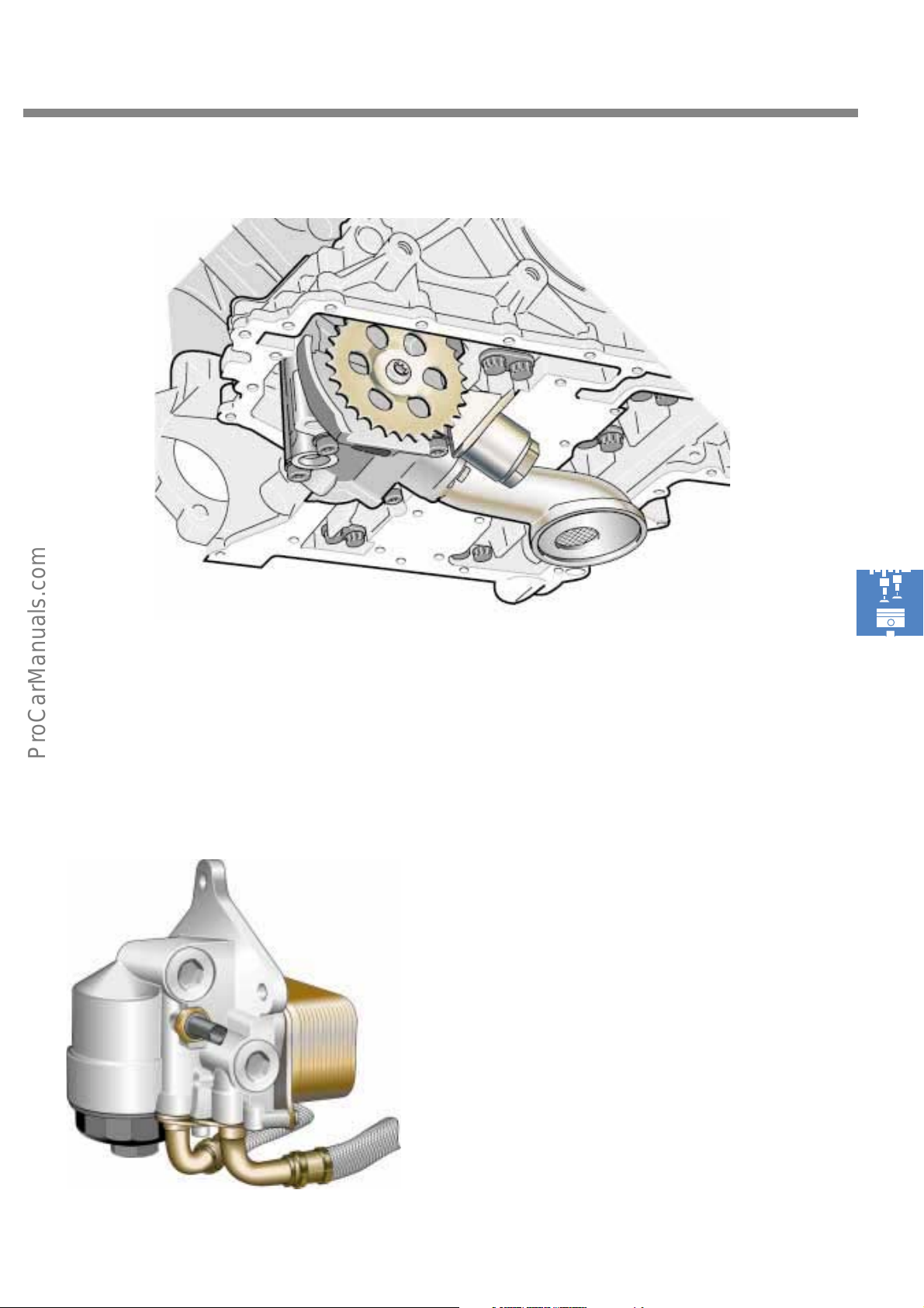
The oil pump is mounted from below and bolted to the bearing support.
The oil filter and cooler module
The oil circuit of the W engine has an external oil
filter and cooler module. This allows the engine
to be more easily adaptable to the varying
amounts of space available in the various vehicle
models. The oil filter is designed so that a filter
element can be replaced by service personnel.
S248_081
Oil filter/cooler module of the W8
S248_095
39
Page 40
Engine mechanicals
The lubrication system
The oil in the oil circuit has a lubricating and cooling function. The W engines are filled with
type 0W30 3.5 engine oil.
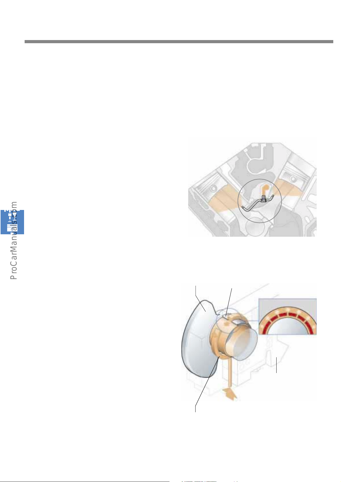
The piston spray jets
The oil is guided from the central oil duct of the
crankcase upper section to small nozzles on the
underside of the cylinder bores. Here, the oil is
sprayed below the pistons in order to lubricate
the piston contact faces and piston pins as well
as to cool the pistons.
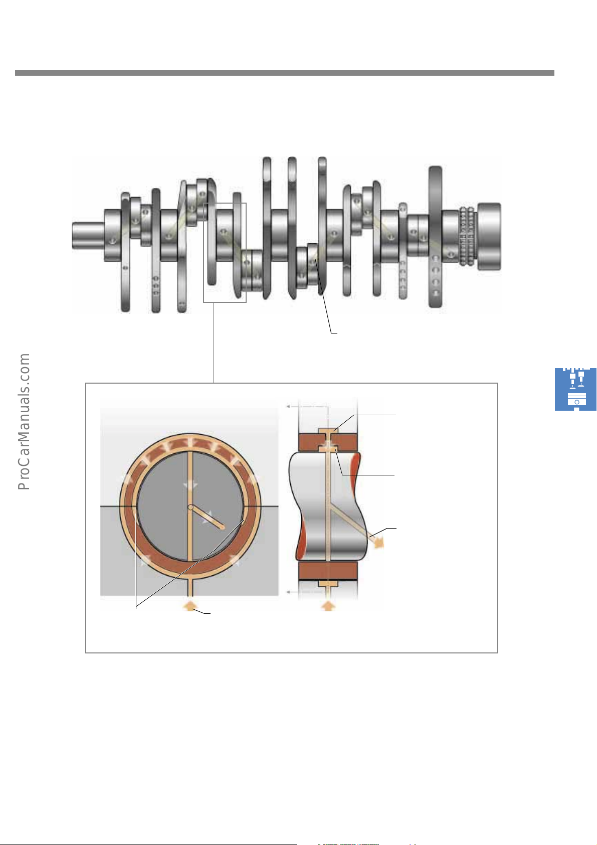
The crankshaft bearing lubrication system
The oil is ducted through bore holes from the
central oil passage to the crankshaft. Then it is
pumped via a groove on the back of the bearing
cups to the upper bearing cup. There it reaches
the crankshaft through five bores in the upper
bearing cup.
S248_093
Crankshaft Upper
bearing cup
S248_092
Bearing support
Oil supply
Groove on the back
of the bearing cups
40
Page 41
Lubrication of the conrod bearings
S248_175
Bore from main bearing
to conrod bearing
Groove in crankcase
Inner groove of bearing
Transitional pockets
Inflow to main bea-
ring
cup (in upper bearing
only)
Inflow to conrod bea-
ring
S248_177
The oil flows from the outer circumferential groove into the inner groove of the upper bearing cup
through five bores. The bore ensures that an even oil film forms.
Integrated pockets at the transition to the lower bearing cup ensure a steady supply of oil to the conrod
bearings via bores in the crankshaft.
41
Page 42
Engine mechanicals
The coolant circuit
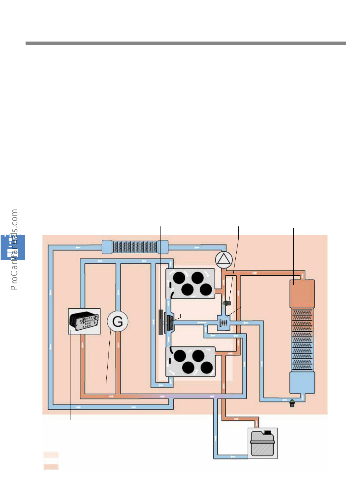
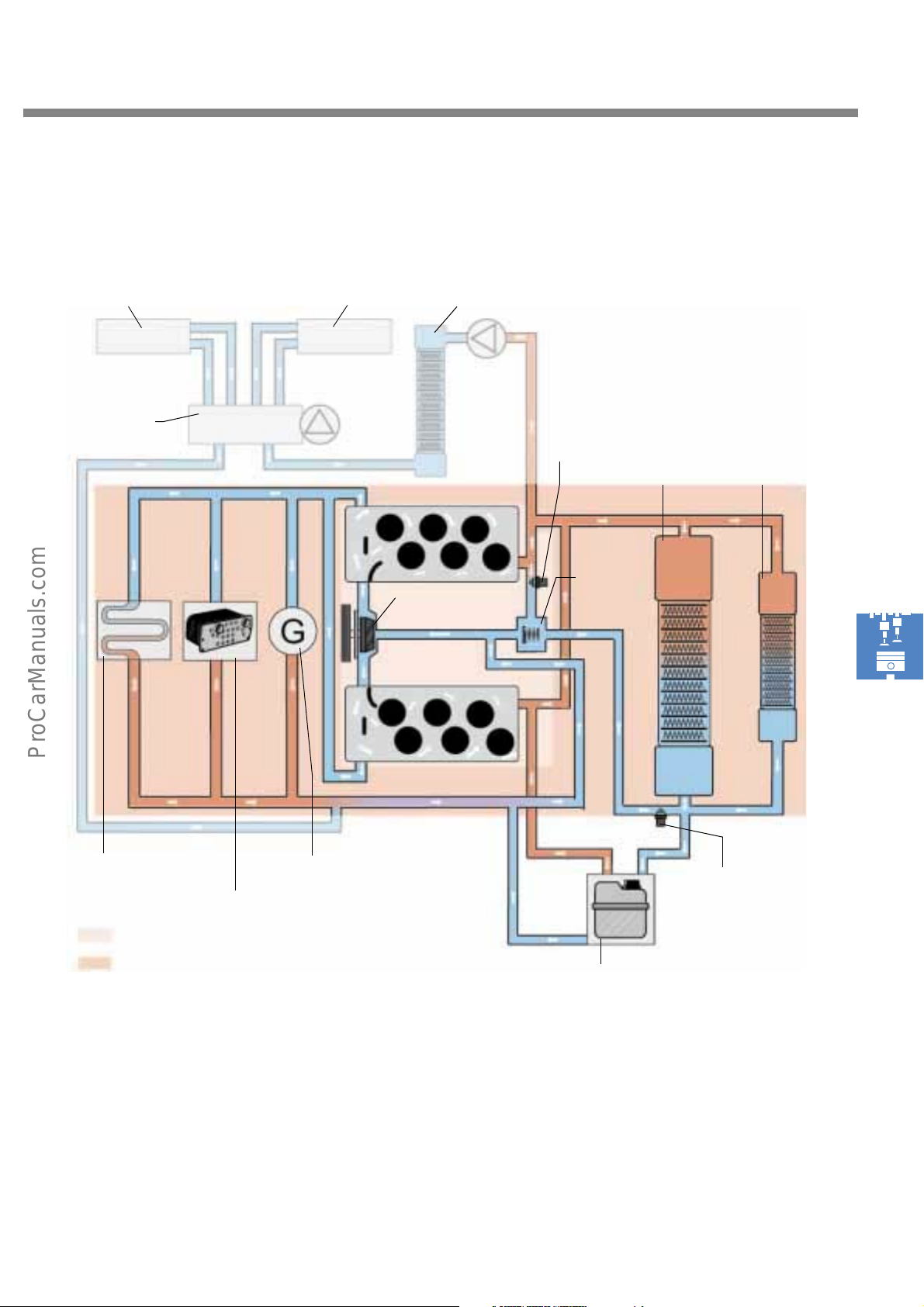
The coolant circuit is filled with VW G12 coolant.
The coolant is channelled out of the central
coolant duct in the crankcase upper section and
into the cylinder heads. Baffles ensure that all
cylinders are swept evenly. At the same time, the
coolant flow is redirected from the exhaust side
of the combustion chambers towards the intake
side.
Coolant circuit of W8 engine
Heating
Ribbed V-belt
The coolant circuit is subdivided into a small
circuit, in which the coolant is only ducted within
the engine block. An outer circuit is located
above the radiator.
Coolant temperature sender
Radiator
Oil cooler
Small cooling circuit
Alternator
Coolant pump
Thermostat valve
S248_098
Coolant
temperature
sender at
radiator outlet
42
Large cooling circuit
Equalising vessel
Page 43
Coolant circuit of W12 engine
Right heat exchanger Auxiliary heater
Cyclical valve
Left heat exchanger
Coolant
pump
Coolant temperature sender
Thermostat
valve
Radiator
Auxiliary
Radiator
Gearbox oil cooler
Engine oil cooler
Small cooling circuit
Large cooling circuit
S248_099
Alternator
Coolant
temperature
sender at
radiator outlet
Equalising vessel
43
Page 44
Engine mechanicals
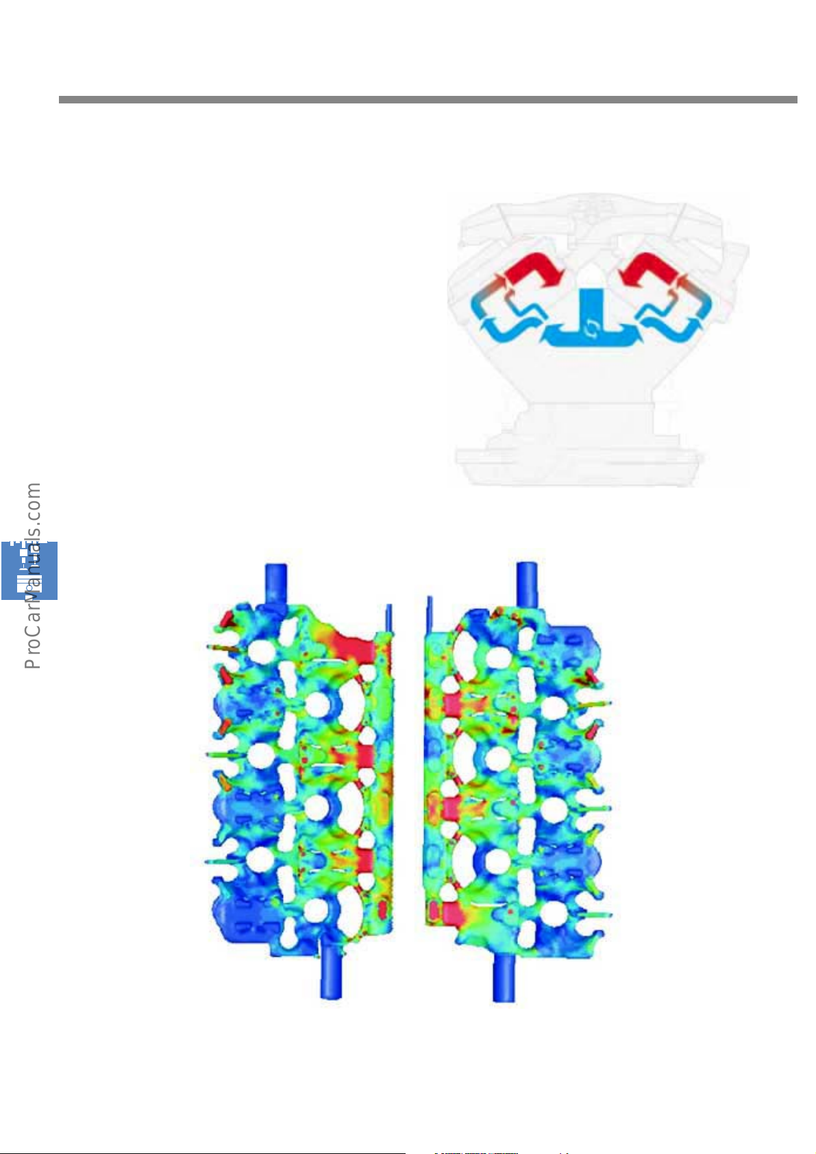
The coolant flow flows from the coolant duct to
the crankcase and into the two cylinder heads. In
the process, two thirds of the volumetric flow is
guided to the outside and one third to the inside
of the cylinder head in question. This principle
helps to provide even cooling, and is known as
cross-cooling.
Coolant flows into the cylinder heads
S248_114
44
S248_115
Coolant flows through the cylinder heads from the exhaust side to the intake side. This results in very
good temperature equalisation as well as effective cooling of the outlet webs and spark plugs.
Page 45
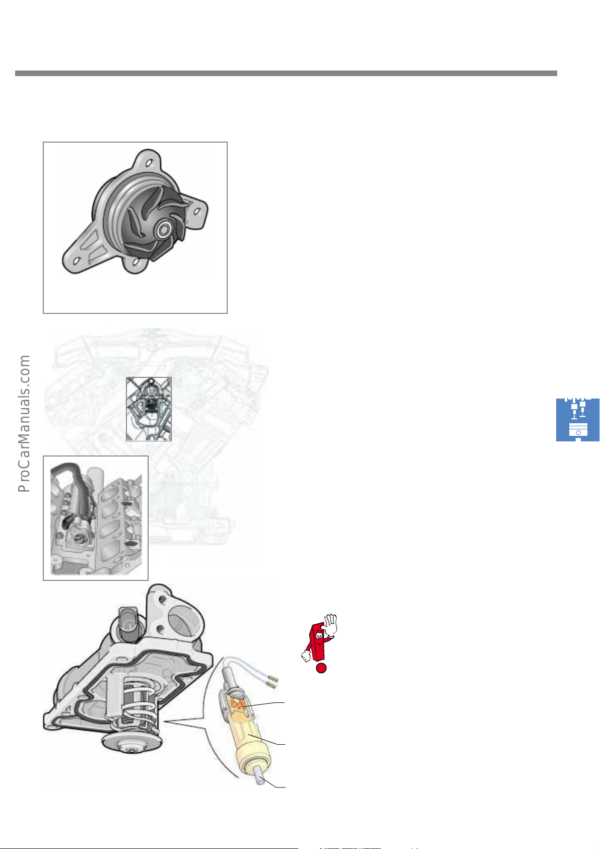
Coolant pump with pump gear
In both W engines, the coolant pump is located
in the cylinder block at the face end. It is
mounted directly upstream of the central coolant
duct and is driven by the ribbed V-belt.
S248_110
Switching over is affected by an electrically
actuated thermostat valve. In the W8 and W12
engine, this valve is installed in the crankcase
upper section from above. To replace this valve, it
is necessary to remove the intake manifold.
By electrically activating the thermostat valve, it
is possible to control the switching point and
coolant temperature. Characteristic maps are
stored in the engine control unit. They make it
possible for the engine to reach the desired
temperature in accordance with the engine's
operating requirements.
S248_112
S248_179
Electrical thermostatic valve for mapped
cooling
S248_111
For detailed information, please refer to
SSP 222.
Heating resistor
Wax t he r mo- c ou p le
Lifting pin
45
Page 46
Engine mechanicals
The air supply
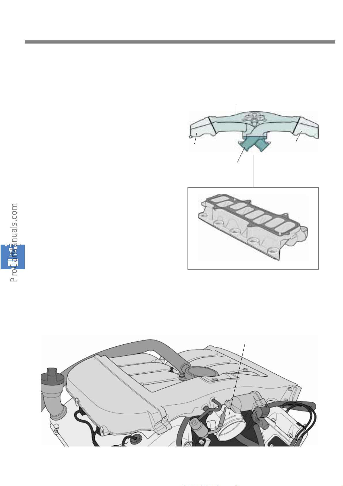
Air is supplied through a tapered intake pipe.
It is of a four-part design and is made of an
aluminium alloy.
The intake manifold lower section is bolted to the
cylinder heads between the two cylinder banks.
The larger intake manifold upper section is
mounted to the lower section. The intake
manifold upper section is designed so that the
manifolds for bank I and II can be detached
separately. The makes it easier to gain access to
the individual ignition coils and spark plugs, for
example.
In the W8 engine, the intake air for both
manifolds is guided by a throttle valve control
unit.
W8 engine
Manifold, bank I
Intake manifold
lower section
Intake manifold upper section
Manifold, bank II
S248_116
S248_117
Throttle valve control unit
46
S248_118
Page 47
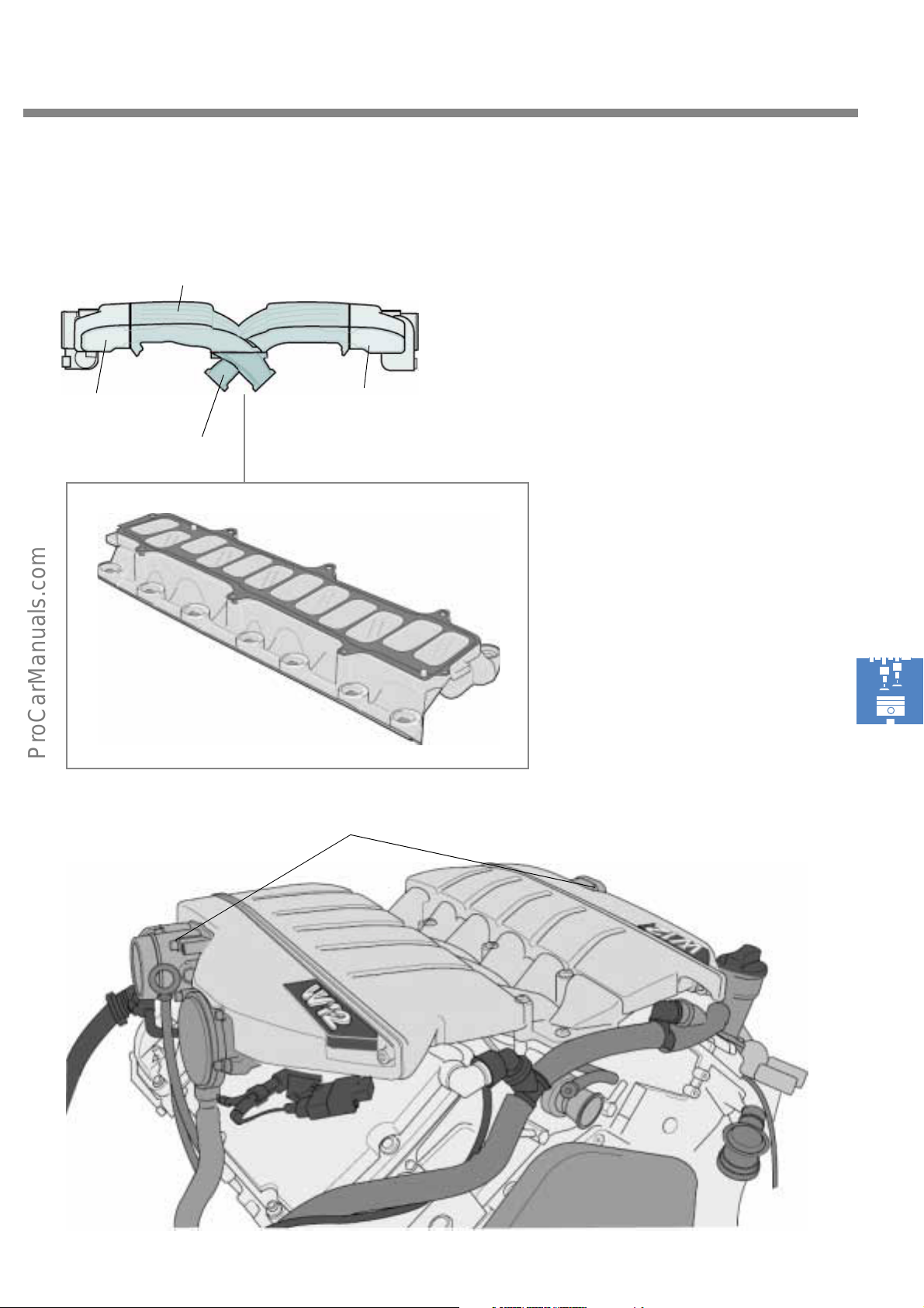
W12 engine
Intake manifold upper section
Manifold, bank I Manifold, bank II
The intake manifold used in the W 12 engine is
made of magnesium alloy. Unlike the W8
engine, each of the manifolds is coupled to a
throttle valve control unit.
Intake manifold
lower section
S248_119
S248_120
Throttle valve control unit
S248_121
47
Page 48
Engine mechanicals
The crankcase breather
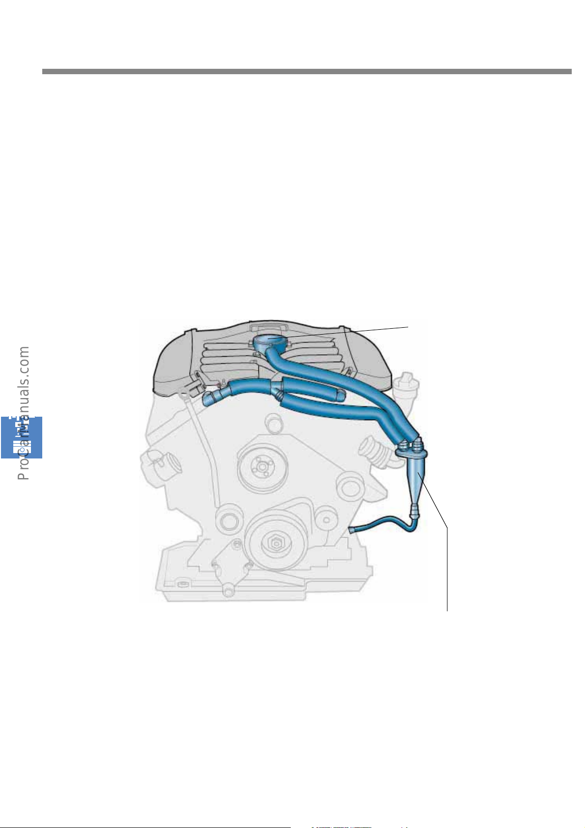
The diaphragm valve limits the vacuum in the crankcase irrespective of the intake pipe vacuum, allowing
the cleaned crankcase exhaust gases (blow-by) to be abducted continuously into the intake manifold and
burnt in the engine. No oil is entrained in the process. The oil separator segregates the oil particles from
the blow-by gas. The separated oil is then returned to the oil sump.
W8 engine
Diaphragm valve
S248_122
Oil separator
48
Page 49
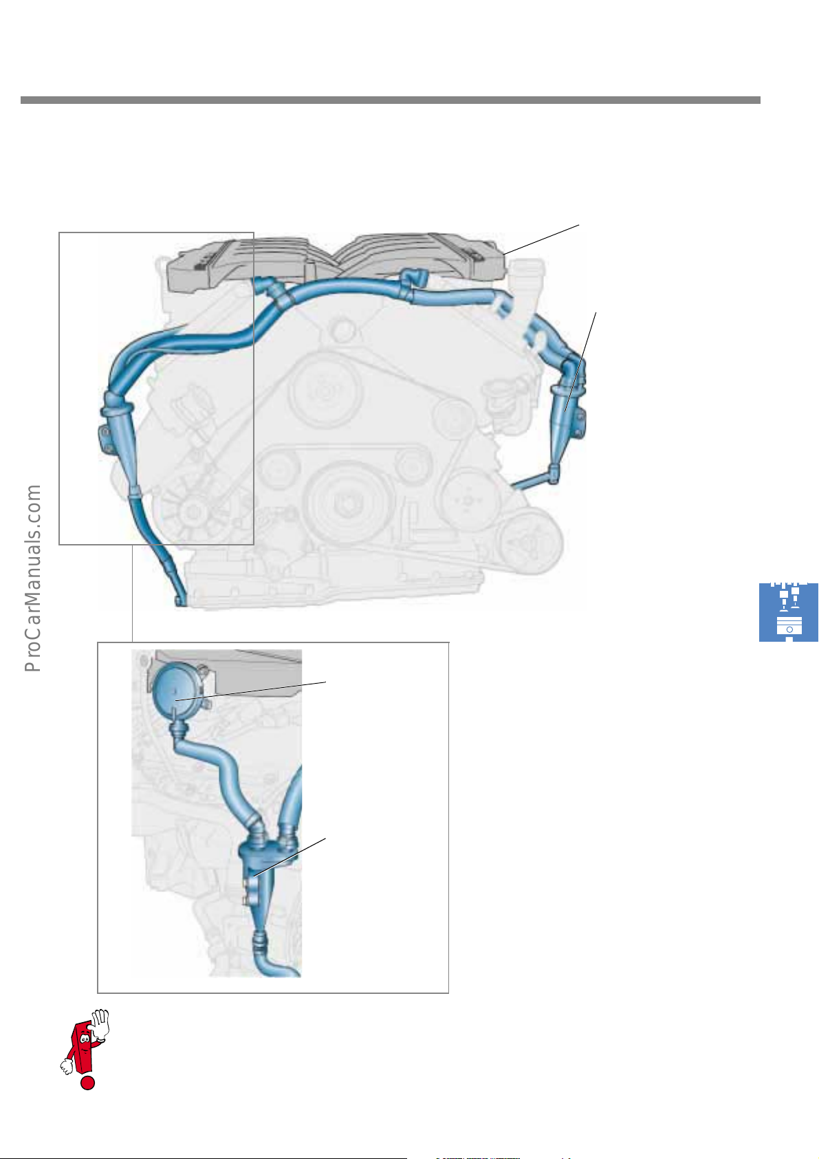
W12 engine
Diaphragm valve,
left
Oil separator
S248_123
As the W12 engine has a double flow intake manifold, each bank has a side diaphragm valve
and an oil separator.
Diaphragm valve,
right
Oil separator
S248_129
49
Page 50
Engine mechanicals
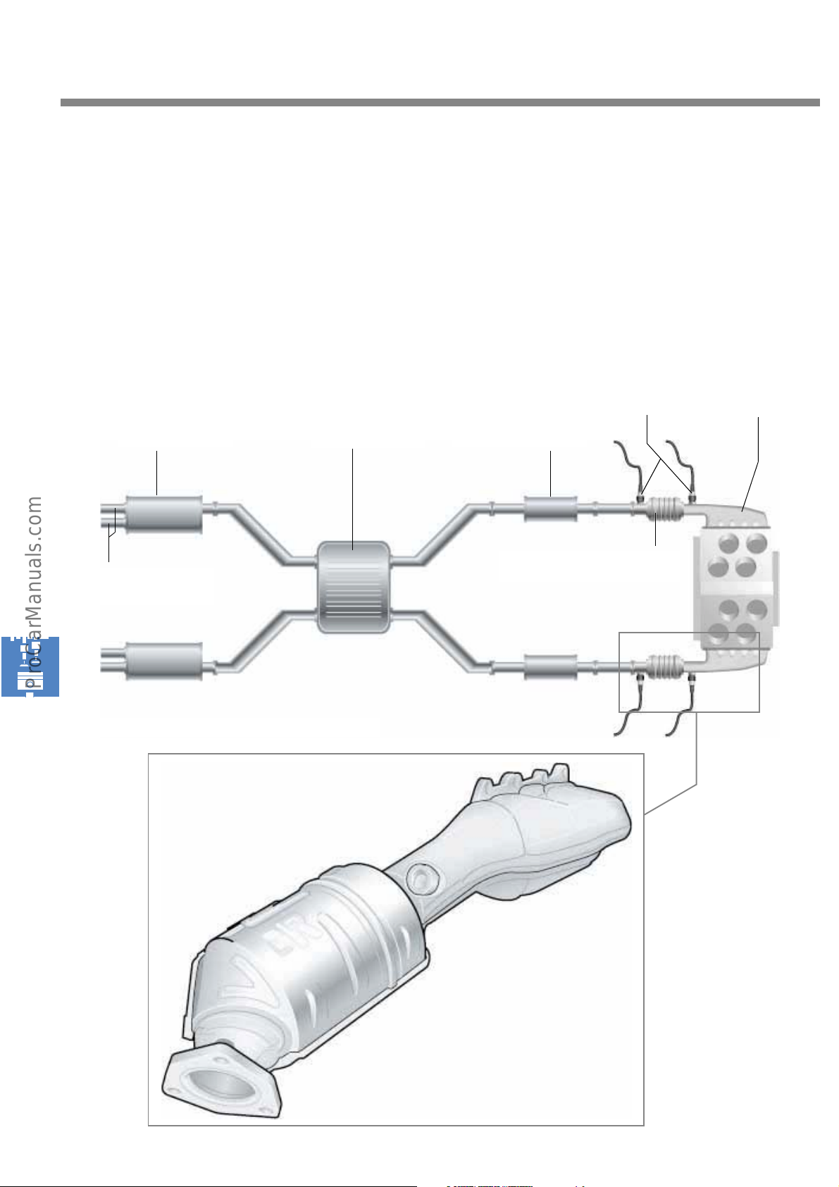
The exhaust system
The W8 engine has an exhaust manifold with a
permanently assigned catalytic converter for
each cylinder head. A total of four lambda
probes are therefore required for emission
control.
Rear silencer
Tai lp ip es
Central silencer
The exhaust system has primary silencer and a
rear silencer for each bank, as well as a common
central silencer.
Lambda probe
Primary silencer
Catalytic converter
Manifold
Exhaust system of W8 engine
S248_124
S248_125
50
Page 51
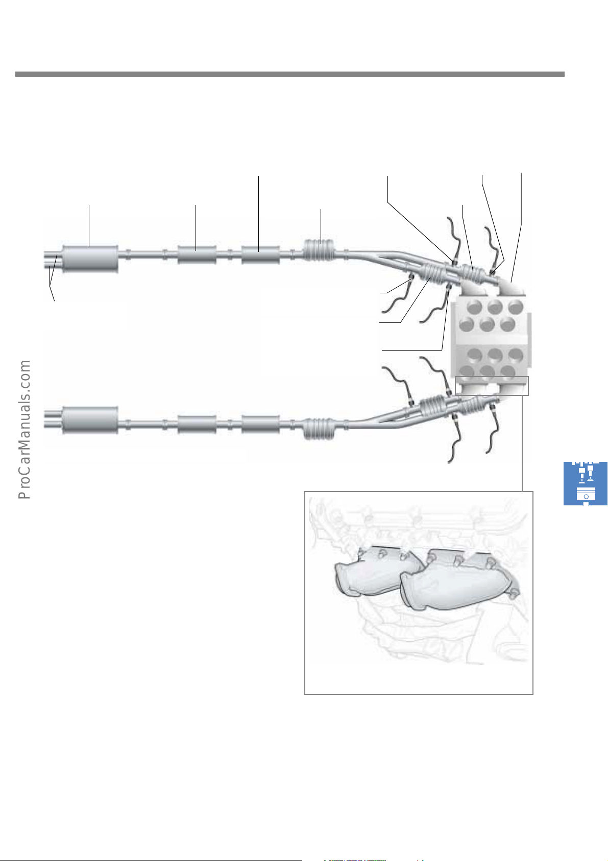
Primary silencer
Lambda probe after
catalytic converter
Lambda probe
before catalytic-
converter
Manifold
Tailpipes
Exhaust system of W12 engine
Central silencerRear silencer
Main catalytic converters
Lambda probe dowstream of
catalytic converter
Primary catalytic converter
Lambda probe upstream of
catalytic converter
Primary catalytic
converter
S248_126
The W12 engine has two exhaust manifolds for
each cylinder head.
Each of these exhaust manifolds is connected to
its own primary catalytic converter located near
the engine. The two exhaust pipes of each bank
then merge on a main catalytic converter. The
exhaust system has a primary silencer, an
intermediate silencer and a rear silencer for
each bank.
Four primary catalytic converters and two main
catalytic converters help to achieve an effective
reduction in emissions.
To monitor mixture combustion and to optimise
pollutant emission reduction, use is made of four
lambda probes before the catalytic converter
and after the catalytic converter
Exhaust manifold
S248_127
51
Page 52
Service
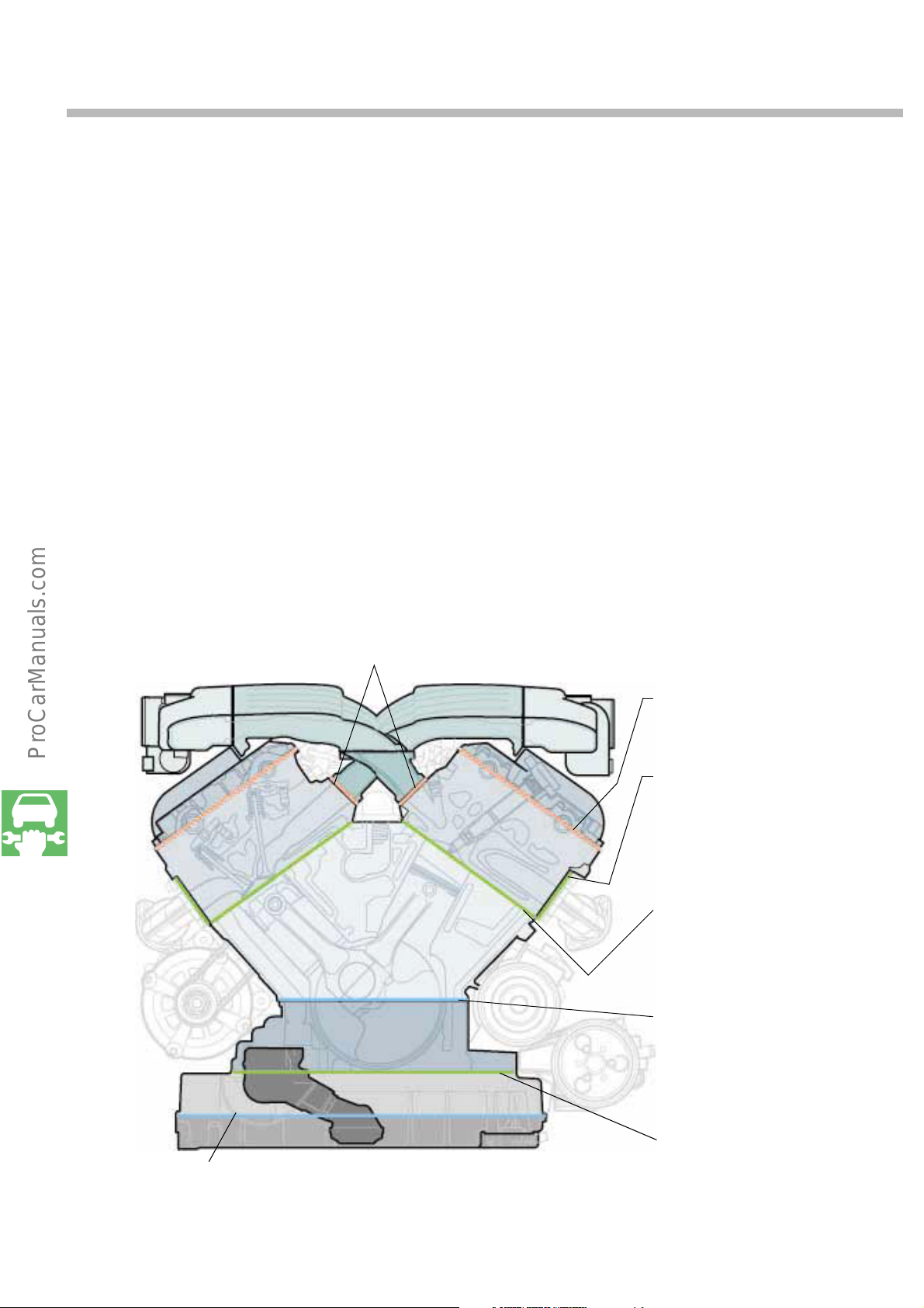
Sealing concept
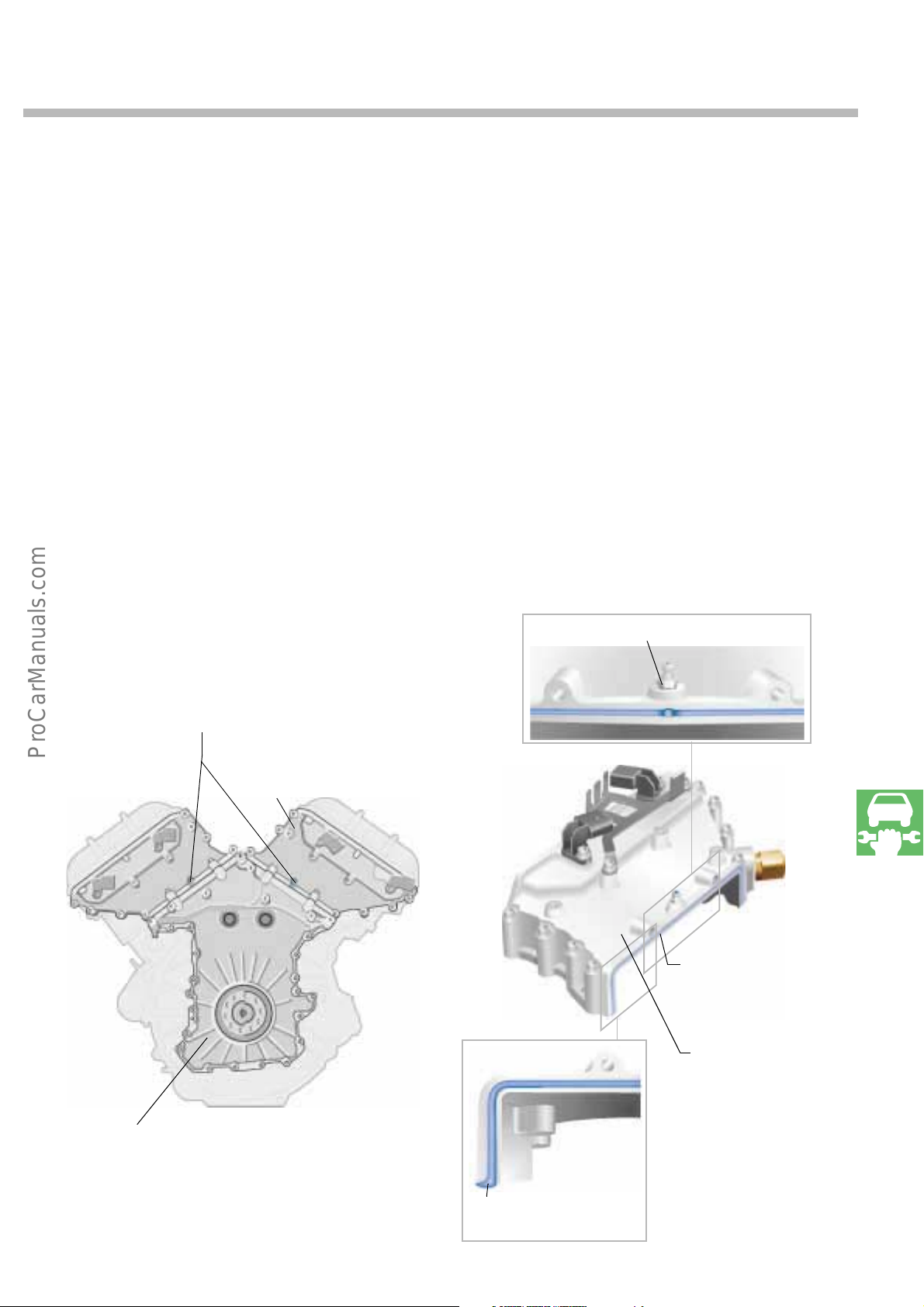
Each of the cylinder heads is sealed off from the
valve covers by a rubber gasket, from the
contact faces of the intake manifold by an
elastomer gasket, from the exhaust manifolds by
a two layer embossed metal gasket and from the
crankcase by a multilayer embossed metal
gasket.
Multilayer metal/elastomer composite gasket
between cylinder head and
intake manifold contact face
The gasket between the bearing support and the
oil sump upper section is also designed as a
single layer embossed metal gasket.
The oil pan upper section and lower section as
well as the crankcase upper section and the bearing support are sealed by means of a liquid gasket.
upper section and lower section
S248_148
Rubber gasket between
cylinder heads and valve covers
Two-layer embossed metal gasket
between cylinder heads and
exhaust manifold
Multilayer embossed metal gas-
ket between cylinder heads and
crankcase
Liquid gasket between crankcase
upper section and bearing sup-
port
Coated embossed metal gasket
between oil sump upper section
and bearing supportLiquid gasket between oil sump
52
Page 53
Liquid gaskets
Application of the liquid gasket sealant is CNCcontrolled in order to ensure a constant sealant
supply. The liquid gasket between the lower
timing case cover and the upper timing case
cover is applied according to a different
principle. In this case, the parts are first bolted,
then the sealant is injected into the groove in the
upper timing case cover via screw nipples
(Sealing Injection System).
When enough liquid sealant has been injected,
the excess sealant is discharged from the
openings on the end of the timing case cover.
The screw nipples remain in the housing after
injecting the sealant. However, they have to be
replaced when repairing the gasket.
Screw nipple
Screw nipple for liquid gasket installation
Lower timing
case cover
(sealing flange)
Upper timing
case cover
S248_140
S248_152
S248_151
Groove for
sealant
Upper timing
case cover
(covering part)
S248_153
Outlet
53
Page 54
Service
Engine timing overview
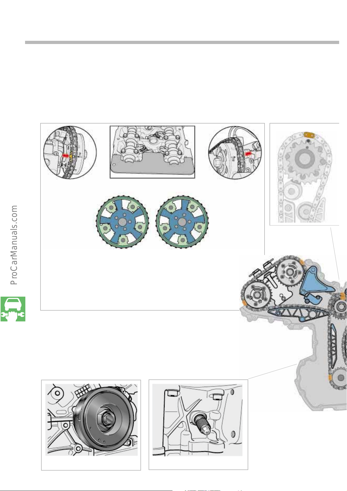
If it is necessary to disassemble the cylinder heads, the engine timing must be reset.
These are the important markers when the piston of the first cylinder is at top dead centre.
Put copper coloured
chain link on arrow
of bank II
Adjust exhaust
camshaft to advance
Position the marker on the vibration
damper on the housing joint:
piston in 1st cylinder at top dead centre.
S248_192
Adjust inlet
camshaft to retard
Insert the mandrel for fixing the
crankshaft into the threaded hole in the
housing:
piston in 1st cylinder at top dead centre.
Put copper coloured
chain link on arrow
of bank II
Bank II
S248_144
54
S248_191
S248_190
Page 55
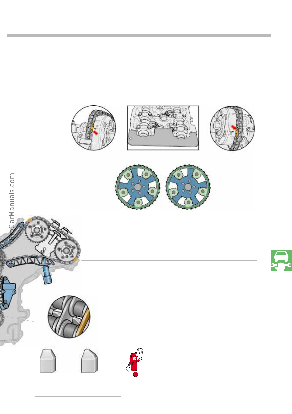
lace the copper
oloured chain link on
he marked tooth of the
ntermediate shaft and
he bore hole in the
ousing
Insert camshaft rule for aligning the
camshafts.
Place copper
coloured chain link
on arrow of bank I
Bank I
S248_193
Inlet camshaft
advance adjustment
When placing on the lower timing chain copper, set the
coloured chain link on the marked tooth and the marked tooth
on the housing joint:
piston in 1st cylinder at top dead centre.
Exhaust camshaft
retard adjustment
Place copper
coloured chain link
on arrow of bank II
S248_178
Normal tooth
For a description of the exact procedure for
setting the engine timing, please refer to the
relevant Workshop Manual.
S248_194
Marked tooth
55
Page 56
Service
Special tools
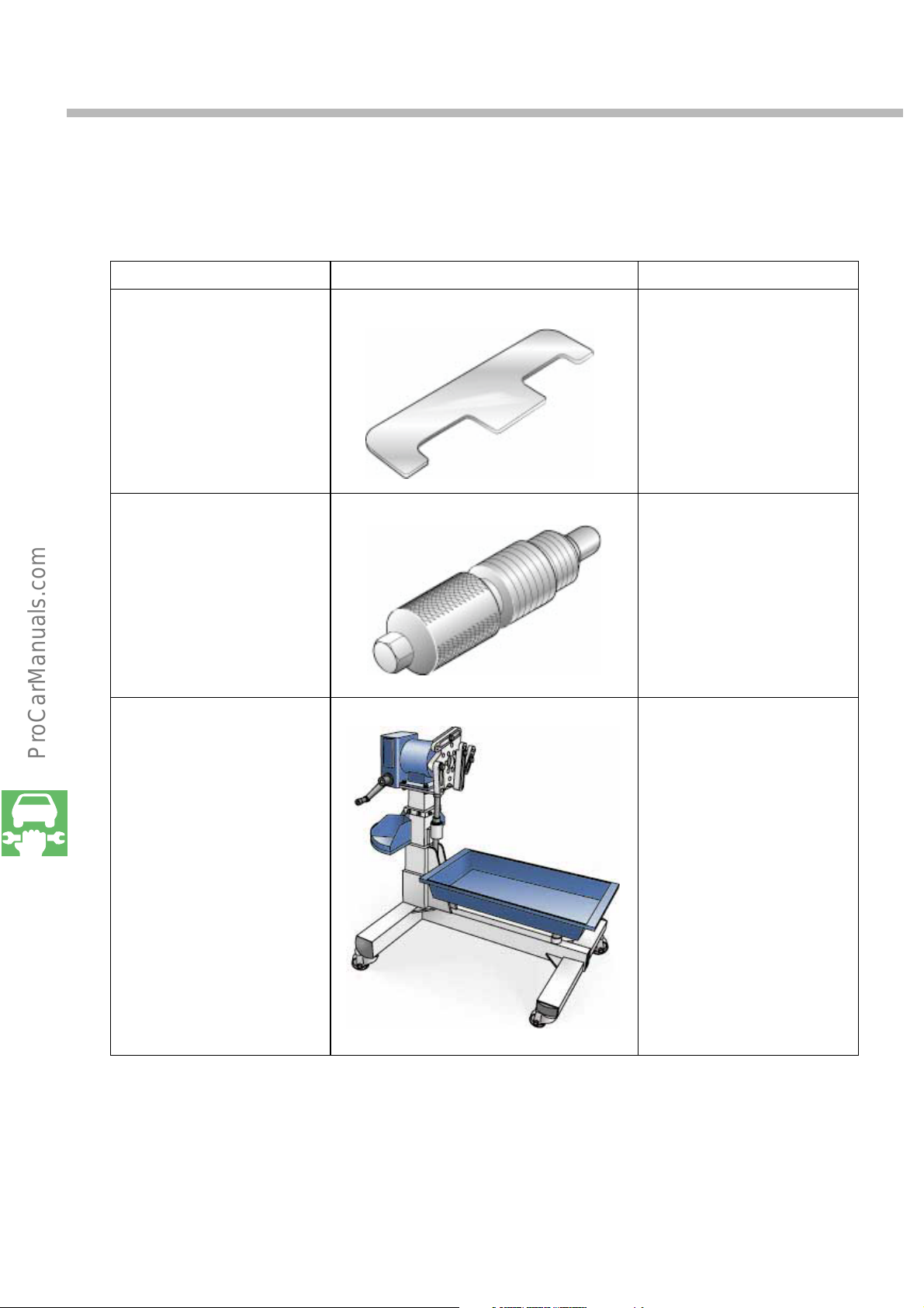
Designation Tool Use
Camshaft alignment rule
Tool No..: T 10068
Mandrel
Tool No.: 3242
Engine and transmission
holder
Tool No.: VAS 6095
For aligning the camshafts
when setting the engine
timing
S248_187
For locating the crankshaft
S248_188
For removing and installing
engines and gearboxes
56
S248_195
Page 57

Notes
57
Page 58

Test your knowledge
1. The cylinders in the W engine are arranged according to the follow principle:
a. two in-line engines arranged in tandem
b. two in-line engines arranged side by side
c. two V engines arranged side by side
2. The W engine has left and right cylinder banks. They are aligned at an angle of:
a. 15°
b. 60°
c. 72°
d. 120°
3. The maximum possible number of cylinders in an engine based on the W engine principle is:
a. W18.
b. W16.
c. W12.
d. W10.
e. W8.
4. What does splitpin mean?
a. an offset amounting to 12.5 mm.
58
b. a crank pin offset which facilitates a regular firing interval.
c. The centre of the crankshaft (fulcrum) is located below the point of intersection of the
intersecting centres of the cylinders.
Page 59

5. Why does the W8 engine have a balancing shaft?
a. to prevent rotary vibrations being transmitted from the crankshaft to the
gearbox
b. to compensate for torsional vibration
c. to compensate for forces of inertia
d. to determine the engine speed
6. A pulse sensor wheel is used to determine the engine speed
a. it is press-fitted onto the crankshaft.
b. it is integrated in the two-mass flywheel.
c. it is located on the gear side of the balancing shafts
7. Which ducts are routed through the cylinder heads?
1.) __________________________________________________________________________
2.) __________________________________________________________________________
3.) __________________________________________________________________________
8. How are the camshafts adjusted?
a. pneumatically
b. hydraulically
c. mechanically
59
Page 60

Test your knowledge
9. The adjustment ranges of the camshaft adjuster between the inlet camshaft and the
exhaust camshaft are different. The exhaust camshaft of the W8 engine can
a. be adjusted continuously!
b. only be adjusted to the advance or retard position!
10. The following units are driven by the pulley drive:
a. the coolant pump
b. the alternator
c. the fuel pump
d. the power-steering pump
e. the air-conditioning compressor
11. Which of the following statements is true?
a. the W8 engine has a wet-sump lubrication system.
b. the W12 engine for VW models has a dry-sump lubrication system.
c. the W12 engine for VW models has a wet-sump lubrication system.
12. Characteristic maps which allow the desired engine temperature to be reached in accor
dance with theengine's operating requirements are stored in the engine control unit.
Which of the following statements is applicable?
a.
There is only one temperature sensor in the cooling circuit, and it is located at the radiator outlet.
60
b. There are two temperature sensors in the cooling circuit.
c. there is only one temperature sensor in the cooling circuit, and it is located at the engine
block outlet.
Page 61

13. Which of the following statements is true?
a. The coolant flows through the cylinder heads from the exhaust end to the intake end.
This ensures very good temperature equalisation as well as effective cooling of the outlet webs
and spark plugs.
b. Coolant flows through the cylinder heads from the intake side to the exhaust side.
This ensures very good temperature equalisation as well as effective cooling of the outlet webs
andspark plugs.
14. A new liquid sealing method is used to seal the upper timing case cover.
The liquid gasket is injected through screw nipples.
a. The screw nipples have to be replaced when repairing the gasket.
b. The screw nipple can be reused any number of times.
c. The screw nipples must be unscrewed after repairing the gasket.
61
Page 62

Notes
62
Page 63

14.) a
13.) a
12.) b
11.) a, c
10.) a, b, d, e
9.) b
8.) b
3 Secondary air ducts
2 Coolant ducts
7.) 1 Oi l d uc ts
6.) b
5.) c
4.) b
3.) b, c, d, e
2.) c
1.) c
Solutions
63
Page 64
248
For internal use only © VOLKSWAGEN AG, Wolfsburg
All rights reserved. Technical specifications subject to change without notice.
140.2810.67.20 Technical status: 08/01
❀ This paper is produced from
non-chlorine-bleached pulp.
 Loading...