

Volkswagen Self Study Program 235 – The Multi-Function Steering Wheel SSP-235-Multi-function-steering-wheel
Page 1
Service.
Self-Study Programme 235
The Multi-Function Steering Wheel
Design and Function
Page 2
MULTIFUNKTION
MULTI-FUNCTIONS
STEERING
CRUISE CONTROL SYSTEM
AIRBAG
RADIO
CASSETTE
CD PLAYER
TELEPHONE
HEIGHT ADJUSTMENT
REACH ADJUSTMENT
Raising the comfort for the driver of a vehicle has always been a high priority for the vehicle
constructor.
The concept of positioning regularly used switches and safety elements on the steering wheel is
the aim of this endeavour.
Originally the regulators for the accelerator and the ignition timing were positioned next to the
horn contact, today in addition to the horn we find levers and buttons for the headlights, turn
signals, cruise control system, radio, telephone, CD player etc.
Apart from this, the steering wheel contains functional elements such as the airbag and, under
certain conditions, a vibration damper.
MULTI-TALENT
…
…
HORN
235_022
Such a versatile steering wheel is known as a multi-function steering wheel (MFW).
The Self-Study Programme presents the design
and function of new developments!
The contents are not updated.
2
Please always refer to the relevant Service literature for current test,
adjustment and repair instructions.
NEW Important
Note
Page 3
At a glance
Introduction . . . . . . . . . . . . . . . . . . . . . . . . . . . . . . . . . . . . . . . . . . 4
Design of MFW . . . . . . . . . . . . . . . . . . . . . . . . . . . . . . . . . . . . . . . 5
Description
Variants
Button assignment
Display
Operation
Electrical circuits . . . . . . . . . . . . . . . . . . . . . . . . . . . . . . . . . . . . . 14
Coil connector
Data transfer
Control unit contact assignment
Self-diagnosis
Function diagram
3
Page 4
Introduction
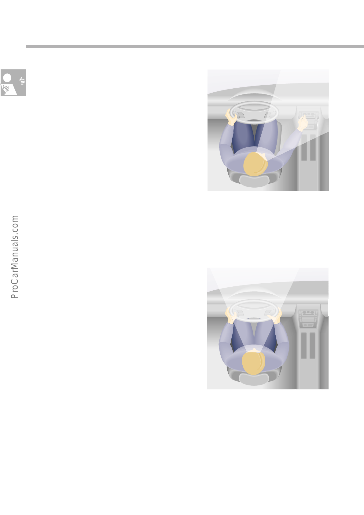
At the moment the driver must remove his hand
from the steering wheel, or even take their eye
off the road ahead, to adjust the volume of a
radio, select another radio station or to operate
the cassette/CD player.
The driver’s attention is distracted from the road
ahead and therefore dangerous situations may
be recognised too late, or even provoked.
235_009
Telephoning in the vehicle, whilst driving, creates
an even more critical situation.
With some hands-free systems the handset must
be held in the hand to dial or send a telephone
number.
Even the use of speed-dial functions may
severely distract a driver.
To reduce these moments of danger and to
increase the convenience factor still further, some
of the regularly used functions for
– the radio,
– the cruise control system (CCS)
– and the operation of the telephone
have been integrated into the rocker switches in
the steering wheel.
235_010
Such an equipped steering wheel is known as a
Multi-function steering wheel (MFW).
4
Page 5
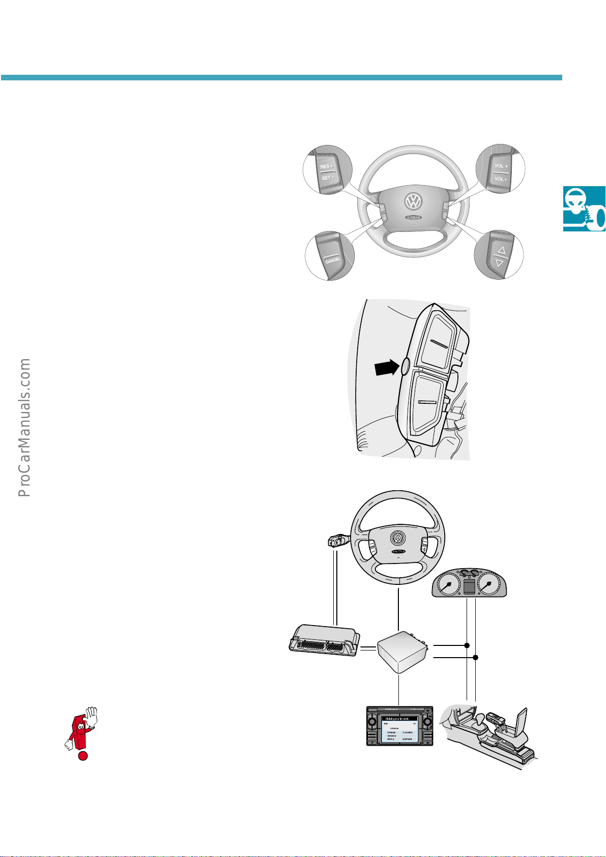
Description
Two switch modules are integrated into the left
and right-hand sides of the airbag unit in the
multi-function steering wheel next, to the horn
controls.
These modules are rocker switches each with two
functions.
These buttons can remotely control
– the radio,
– the cruise control system (CCS)
– and the telephone.
An additional button in integrated into the back
of the left-hand button module to switch-off the
illumination of the buttons.
There is a short delay when switching the
illumination ON/OFF.
MFW design
235_020
R
E
S
+
S
E
T
-
CANCEL
The electrical connections between the steering
wheel electronics and the onboard supply is
established via a coil connector in the steering
wheel.
The transfer of data between individual
components is via a single wire data bus.
The central display of the combi-instrument in the
dash panel insert (Highline display), displays the
radio station, the CD title/number or the name
and telephone number stored on the telephone
SIM card when audio/telephone system is in
operation.
Some models have a vibration
damper in the multi-function
steering wheel (MFW) to reduce
vibrations.
235_026
F
F
F
F
O
O
N
N
O
O
S
S
E
E
R
R
CAN
CAN-H
CAN-L
235_018
5
Page 6
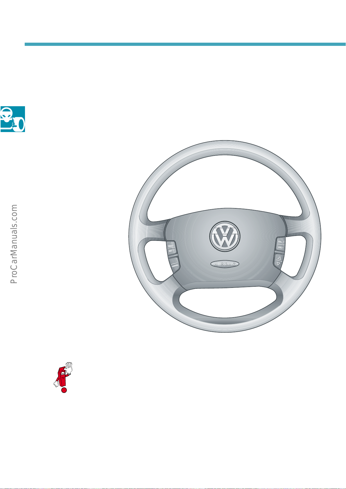
MFW design
Variants
The multi-function steering wheel is available in
two different versions:
Audio/CCS variant
MFW can remotely control functions of the radio
and CCS.
A button to control the illumination of
the buttons on the steering wheel is
also integrated.
Audio/CCS/telephone variant
In addition to the above
mentioned functions, the fitted
telephone can also be controlled from
the steering wheel.
A button to control the illumination of the
buttons on the steering wheel is also integrated.
With both variants of MFW, the
selection of radio, cassette or CD
changer operation is made
directly on the radio unit as
before.
235_019
6
Page 7
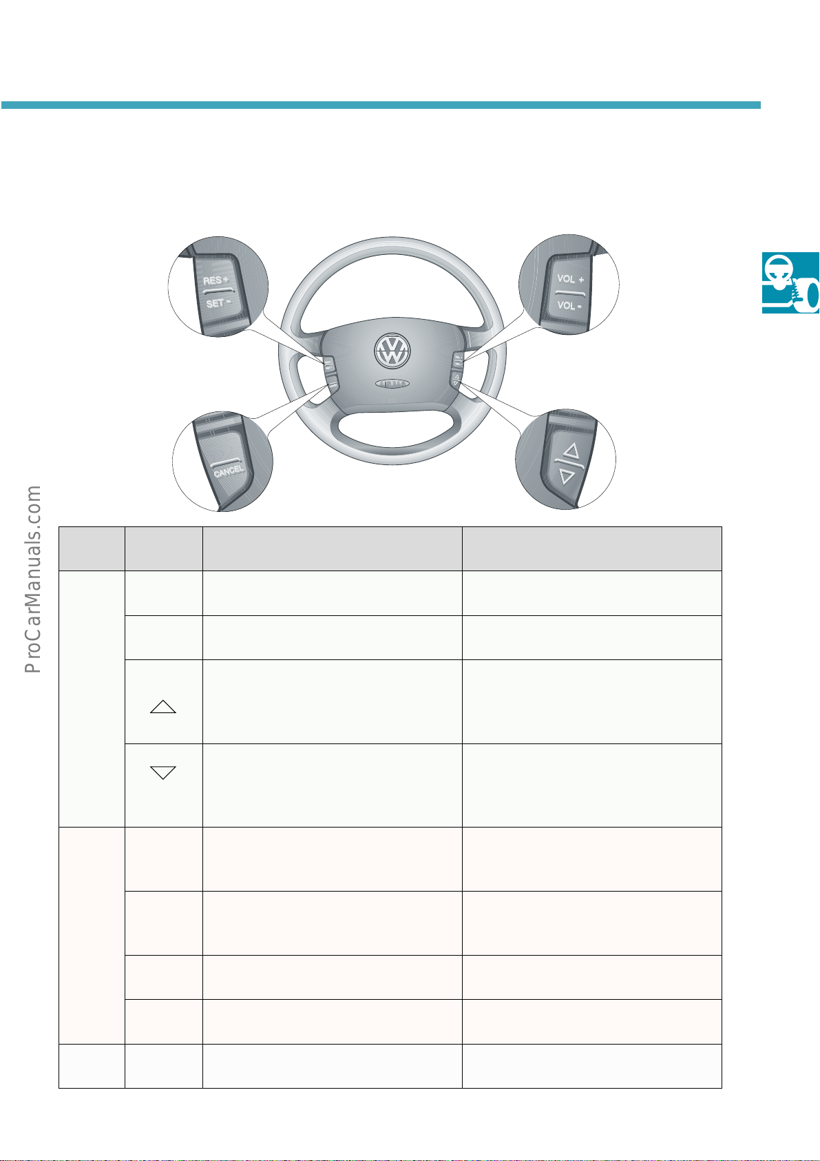
Button assignment
Audio/CCS variant
235_020
Button
module
Right VOL + Volume “up“
Left RES + Resume
Button
symbol
Louder
VOL – Volume “down“
Quieter
Scroll “up“
Station search up
Scroll “down“
Station search down
Resume stored speed
SET – Set
Store or reduced speed
Function Significance
Increases volume
Decreases volume
Radio: Station search, up
Cassette: Fast forward
CD: Title search forwards
Telephone: Scroll up
Radio: Station search, down
Cassette: Fast rewind
CD: Title search backwards
Telephone: Scroll down
Speed of vehicle will increase or will
be resumed
Current speed will be stored or
reduced
Vacant Vacant Blocked mechanically
CANCEL CCS off; Switches CCS off
Rear Button illumination Button illumination ON/OFF
7
Page 8
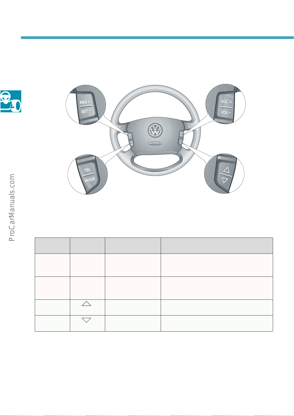
MFW Design
Button assignment
Audio/CCS/telephone variant
The lower rocker of the left-hand button module
is assigned differently to the Audio/CCS variant.
Button
module
Lower left
Lower right Search telephone
235_021
Button
symbol
TEL Telephone Initiate call
MODE Change-over For radio/CC/CD: switch to telephone mode
book
Function Significance
Accept call
End call
For telephone: switch to radio mode
Search telephone book upwards
Search telephone book downwards
The CCS function “CANCEL“ is controlled from
the CCS switch.
8
The functions for the horn and airbag remain
unchanged.
Page 9
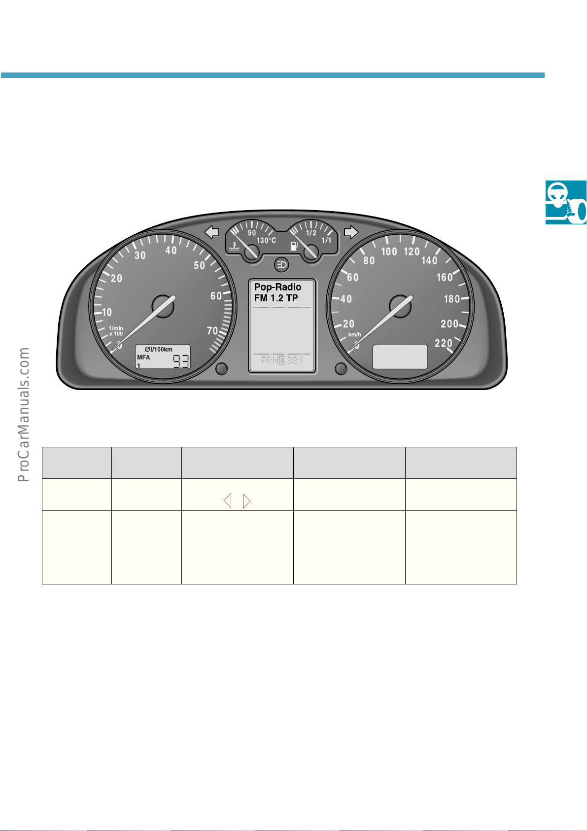
Display
Highline display
Example: Radio mode
235_012
MODE Radio Compact cassette
Display
Pop-Radio
FM 1.2 TP
Significance Station
name
Cassette
forwards or rewind
Station
frequency
* The name of the subscriber is displayed when the
name is stored. Otherwise the number transmitted
will be displayed or “Call“, will be displayed when
no number is transmitted.
CD player Telephone
(CC)
TAPE CD 02
TR 09
CD number
Title number
MEIER
0234567
Name or telephone
number of subscriber
*
9
Page 10
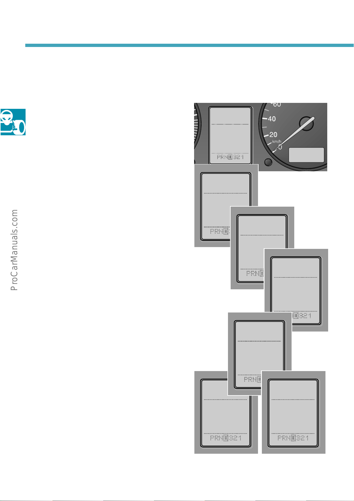
MFW design
When in telephone mode additional display
texts are activated.
They equate to the standard operating texts
displayed by a mobile telephone etc.
Following texts can, for example, appear on the
display:
Connection to transmitter is not possible;
connection will be disconnected
No telephone (SIM) card in telephone unit
Enter PIN code
NO
SERVICE
CARD
PLEASE
235_005
PIN
PLEASE
PLEASE
WAIT …
Telephone (SIM) card being read
Incoming call
Line engaged
CALL
DIAL
ENGAGED
235_006
10
Page 11

Operation
Example: telephone
Incoming call
– Telephone rings,
in central display; press
hand button module
– The hands-free system switches to
“ON“
automatically
– When the telephone number of the
caller is stored on the telephone SIM
card, the callers name appears on the
central display of the combi-instrument
–
Telephone
– Once call has ended press
– The hands-free system switches to
“OFF“
– Call ended
–
With
radio mode
or
if the function “Accept calls
automatically“ is activated:
– The hands-free system switches
automatically to
–
Telephone
– The subscriber ends call and the hands-
free system automatically switches to
“OFF“
automatically
“MODE“
“CALL“
as normal
“END CALL“
button you can return to
“ON“
as normal
e.g. appears
“TEL“
after 3 rings
on left-
“TEL“
button
Outgoing call
Depress
–
function
“ “ (lower right-hand button module),
to scroll through the telephone book
until the required name or telephone
number appears on the central display
of the combi-instrument;
Once the item desired appears press
“TEL“
number displayed;
“DIAL“
Once the subscriber has accepted the
–
call the hands-free system switches to
“ON“
If the number dialled is engaged then
–
“ENGAGED“
display
Calls are ended by pressing the
–
button;
the hands-free system switches to
“OFF“
– Call ended
–
With
radio mode
Note:
Pressing once:
jumps to next entry;
Pressing longer (approx. 2 seconds);
scrolls through alphabetically;
“MODE“
“TEL“
button and telephone dials the
appears in the central display
“MODE“
button to change to
; use button “ “ and
appears on the central
“END CALL“
button you can return to
“TEL“
11
Page 12
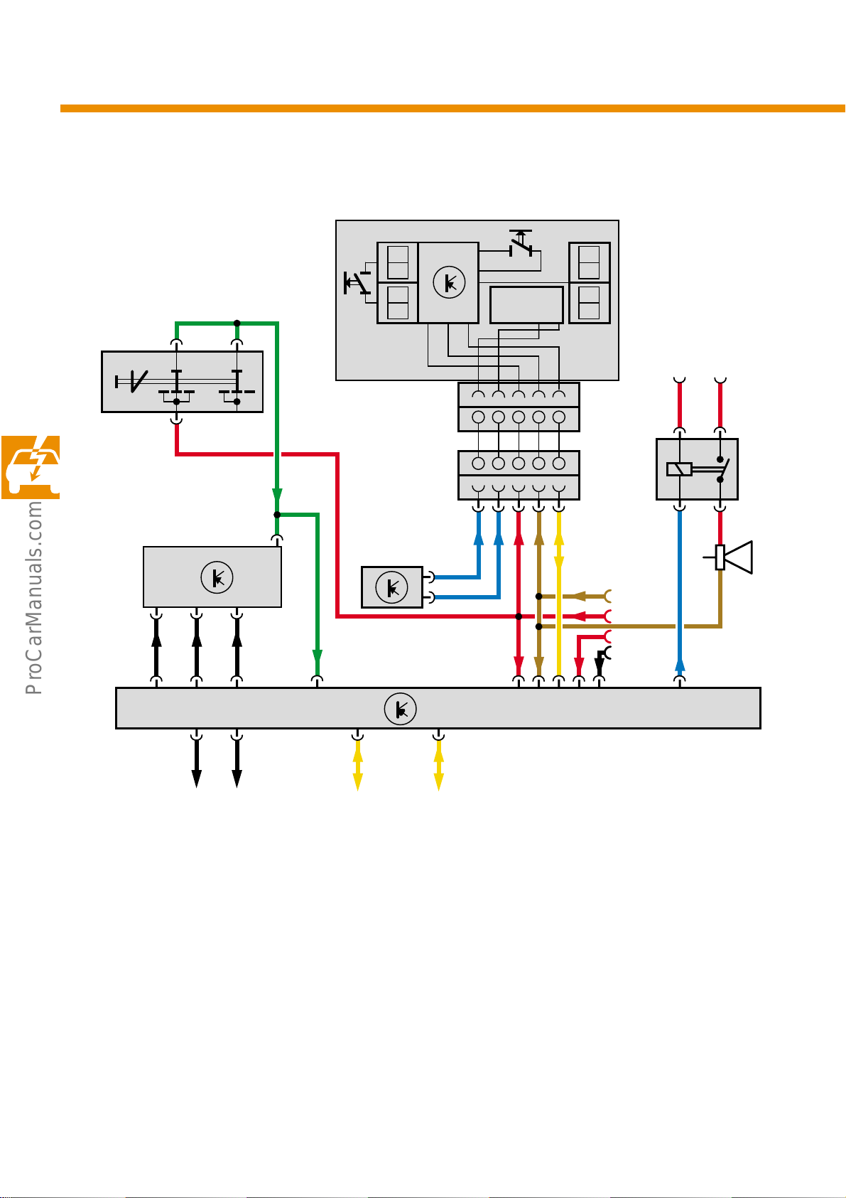
Electrical circuits
Block circuit diagram
E221
H
Airbag
T
123
N95
E45
ON OFF
7
65
J...
EW-
4
X
30
12 345
L
L
J234
12 345
54 321
54 321
J453
F138
J4
CAN
3115
H1
31
15
30
*
58d
12
KR
*
CAN-H CAN-L
E 45 CCS switch
E221 Multi-function steering wheel
(steering wheel operating unit)
F138 Coil connector
H Horn plate
H1 Horn
J… Engine control unit
J4 Dual tone horn relay
* when CAN, then R and 58d are omitted
**
(optional)
J234 Airbag control unit
J453 Multi-function steering wheel control
K Diagnostic connection
N95 Airbag igniter, driver’s side
R Radio
T Button for illumination of button
235_017
unit
module
Page 13
Coil connector
Design and function
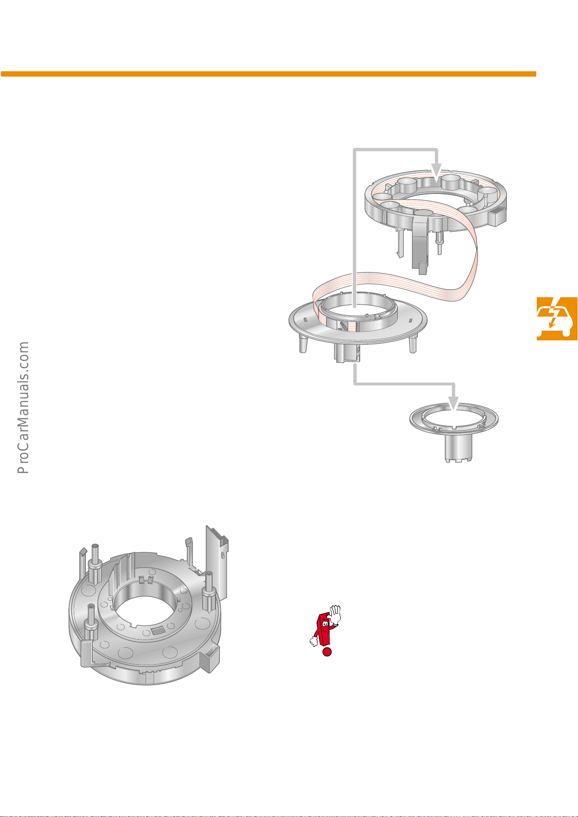
The electrical connection between the rotating
steering wheel, with its steering wheel
electronics, and the onboard electrics is provided
by a highly flexible coil connector.
With increased desires for more comfort and
safety, ever more functions are being controlled
from the steering wheel. The number of available
conductors is limited.
The multi-function steering wheel uses a coil
connector with five conductors.
These circuits are printed on a highly flexible
strip.
The five conductors are used for:
– the triggering of the driver’s airbag (2 con-
ductors),
– the current supply for the operating units in
the steering wheel (2 conductors) and
– the CAN wiring (1 conductor)
235_027
The coil connecter fitted into the
steering angle sender G85
functions analogously.
F138 Airbag coil connector
235_028
13
Page 14
Electrical circuits
Data transfer
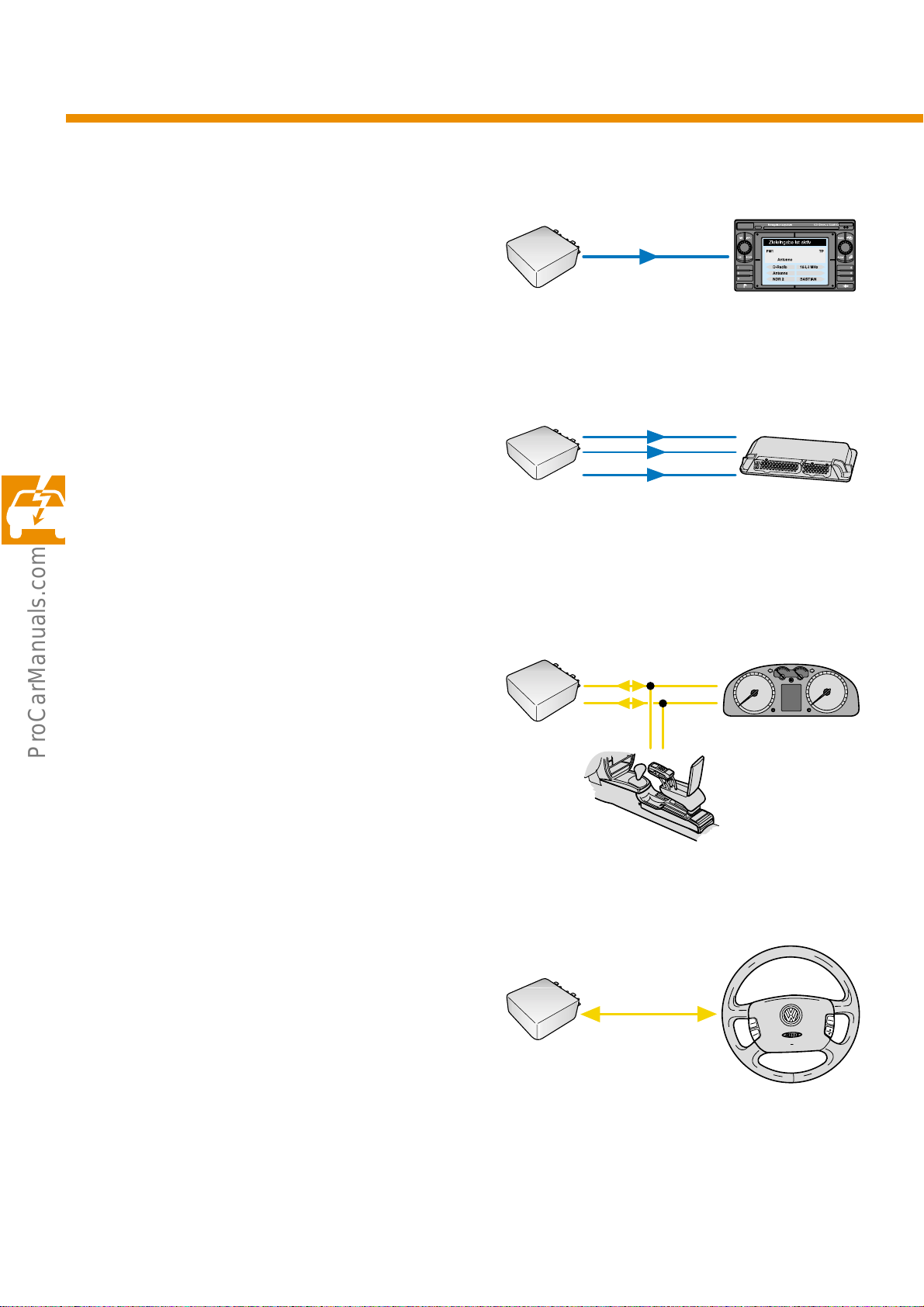
… between multi-function steering wheel control
unit and radio is via the remote control interface
for the radio/RNS (radio connector C 2, pin 11).
PIN6
C2
PIN11
235_001
… from multi-function steering wheel control unit
to engine control unit to remotely control the
cruise control system (CCS) direct via the wiring
(pin 16 and 8) and CANCEL CCS.
… from multi-function steering wheel control unit
to dash panel insert for the displays and
telephone interface via the convenience data
bus (Infotainment CAN).
The function of the telephone is not implemented
into the hardware or the software of the multifunction steering wheel, but is a component part
of the telephone system.
RES+
PIN16
PIN8
SET-
14
PIN3
PIN1
GRA
GRA
CAN high
CAN low
W
-
235_002
235_004
14
… from multi-function steering wheel control unit
to steering wheel electronics via the coil
connector.
PIN18
PIN5
CAN
235_003
Page 15
Contact assignment of multi-function
steering wheel
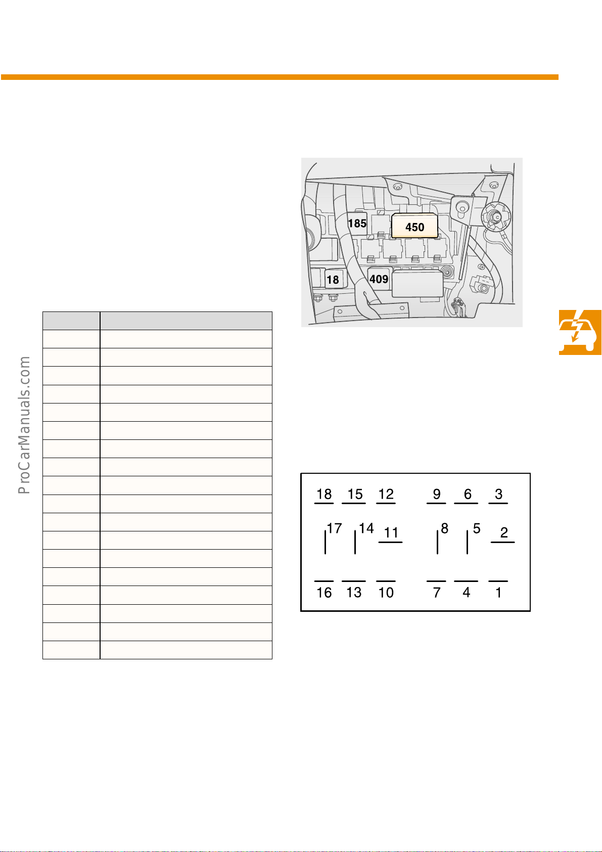
The multi-function steering wheel (MFW) control
unit is located in a double relay housing on the
central electrics relay carrier as relay No. 450.
The pin assignment is shown in the following
table.
Contact Function
1 Convenience data bus, low (CAN-L)
2 Reserved
3 Convenience data bus, high (CAN-H)
4 CCS OFF
5 Remote control of radio
6 Diagnostic cable K
7 Reserved
8 CCS SET
9 Dual tone horn relay
10 Terminal 31
11 Reserved
12 Terminal 15
13 Terminal 30
14 CANCEL CCS
15 Terminal 58d
16 CCS RES
17 Reserved
235_007
235_014
18 Data bus for steering wheel electronics
Technical status October 2000
15
Page 16
Electrical circuits
Self-diagnosis
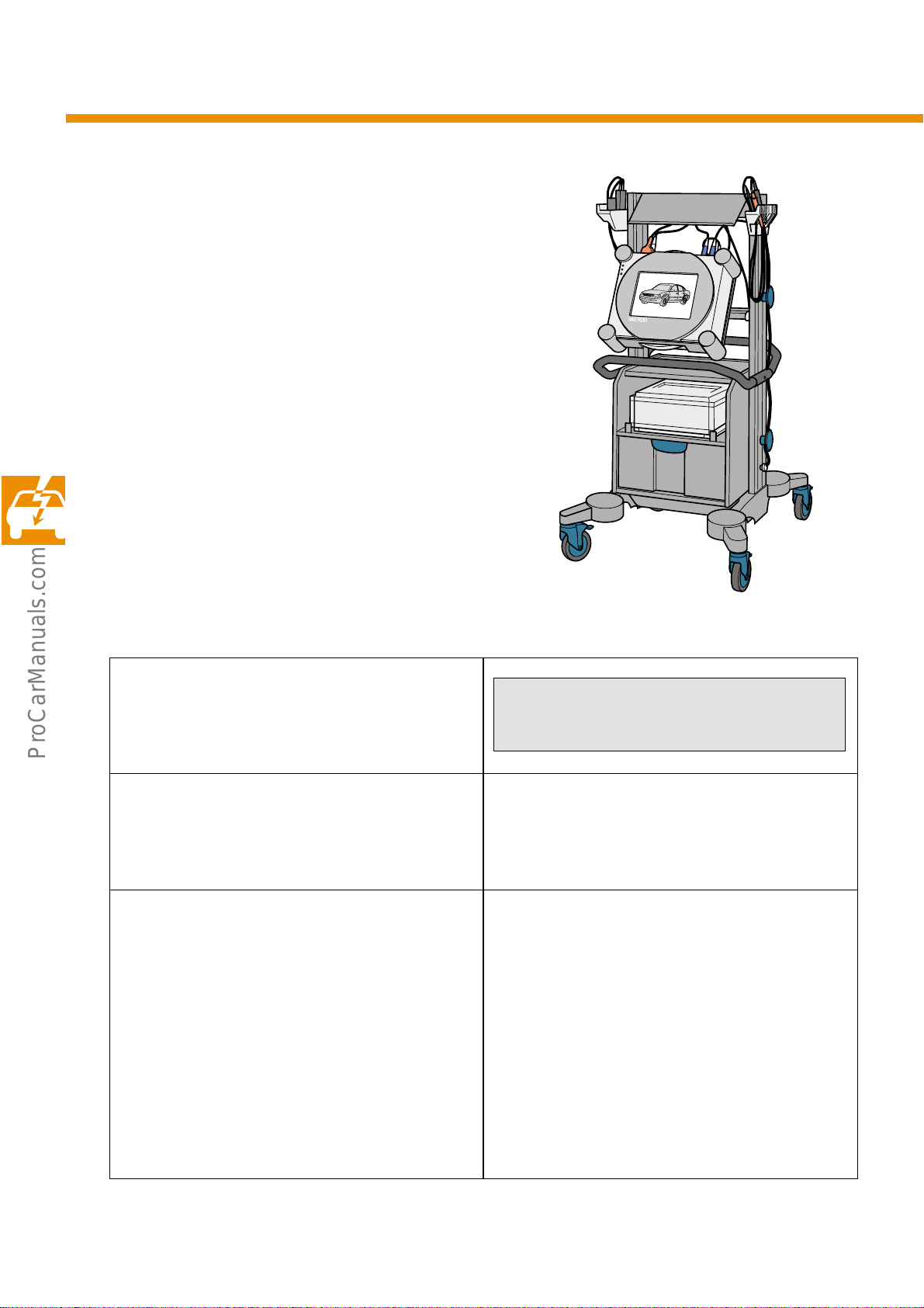
Vehicle Diagnosis, Testing and Information
System can be used for the following diagnosis
functions:
01 - Interrogate control unit version
02 - Interrogate fault memory
03 - Final control diagnosis
04 - Not used
05 - Erase fault memory
06 - End output
07 - Code control unit
08 - Read measured value (data) block
Address word for self-diagnosis
16 - Steering wheel electronics
01 - Interrogate control unit version
02 - Interrogate fault memory 01426 Operating unit in steering wheel E221
03 - Final control diagnosis
Following functions are activated one after the
other:
Radio louder
Radio quieter
Radio station search upwards
Radio station search downwards
MODE
Telephone memory
Next item in telephone memory
END
235_029
1J0907487 Steering wheel electronics xx.xx—>
Coding: 00008 WSC
No communication,
Implausible signal;
65535 Control unit defective
Radio volume increases audibly
Radio volume decreases audibly
Seeks next radio station, display
Seeks previous radio station, display
Changes between audio and telephone modes
Seeks first name in telephone memory, display
Seeks next name in telephone memory, display
End of final control diagnosis
16
Page 17
07 - Code control unit
e.g. 00008 Audio/CCS
08 - Read measured value block (data block)
001
– Quieter button
– Louder button
– Search down button
– Search up button
002
– CCS RES button
– CCS SET button
003
– Telephone button
– MODE/CCS OFF button
Quieter (button not operated)
Louder (button not operated)
Down (button not operated)
UP (button not operated)
RES/+ (button not operated)
SET/– (button not operated)
not operated/operated
not operated/operated
17
Page 18
5
5
1
1
Electrical circuits
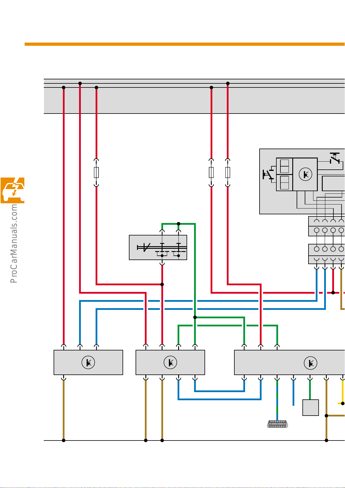
Function diagram, example: version Audio/CCS
30
15
E221
H
SSS
Airbag
T
123
N95
J234 J220 J453
E45
ON OFF
74
65
1234
1234
5432
5432
18
31
*
58d
*
R
Page 19
5
5
F138
1
1
CAN
30
X
75 30
71
CAN-BUS H
J4
*
30
15
S
D
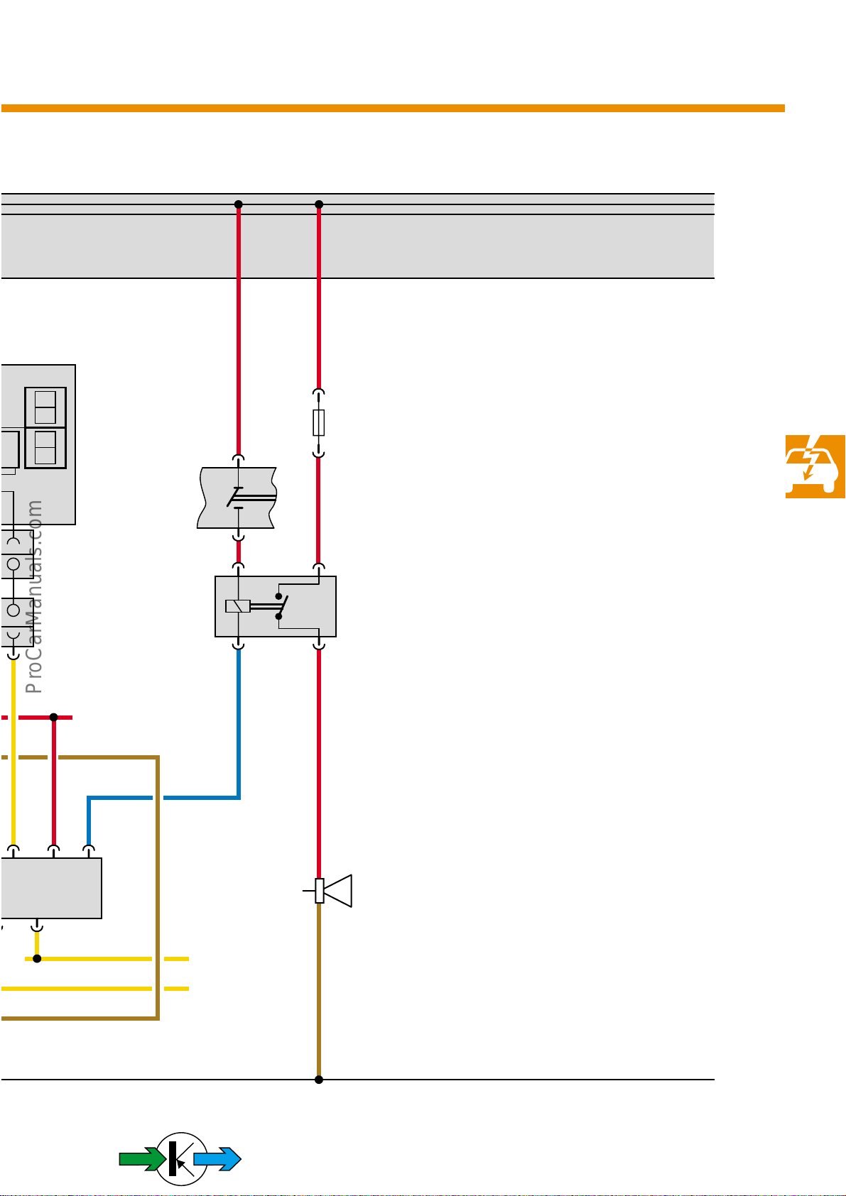
Version with Audio/CCS
87
Legend
D Ignition/starter switch
E45 CCS switch
E221 Operating unit in steering wheel
F138 Coil connector for airbag/return spring
with sip ring
H Horn plate
H1 Horn/dual tone horn
J4 Dual tone horn relay
J220 Motronic control unit
J234 Airbag control unit
J453 MFW control unit
H1
N95 Airbag igniter, driver’s side
R Radio
S Fuse
T Button for illumination of button module
CAN-BUS L
in out
*
* when CAN, then R and 58d are omitted
31
235_023
19
Page 20
Service.
235
For internal use only © VOLKSWAGEN AG, Wolfsburg
All rights reserved. Technical specifications subject to change without notice
040.2810.54.20 Technical status 07/01
This paper is produced from
❀
non-chlorine-bleached pulp
 Loading...