

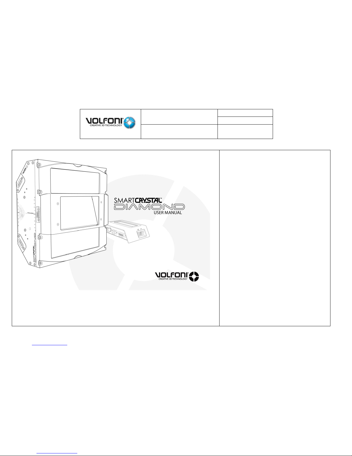
SmartCrystal™ Diamond
n ° : MUV140036
Version : A12
USER MANUAL
Date : 11/01/2018
www.volfoni.com This document is the property of the Co VOLFONI and may not be reproduced or disclosed without permission. 1
model
VPSP-08000
VPSP-08100
VPSP-08200

SmartCrystal™ Diamond
n ° : MUV140036
Version : A12
USER MANUAL
Date : 11/01/2018
www.volfoni.com This document is the property of the Co VOLFONI and may not be reproduced or disclosed without permission. 2
TABLE OF CONTENTS
INTRODUCTION --------------------------------------------------------------------------------------------------------------------------------------------------------------------------------------------- 5
General points -------------------------------------------------------------------------------------------------------------------------------------------------------------------------------------------- 5 a.
Contents of this manual -------------------------------------------------------------------------------------------------------------------------------------------------------------------------------- 5 b.
Specification of the projector ------------------------------------------------------------------------------------------------------------------------------------------------------------------------- 6 c.
Specification of the bracket ---------------------------------------------------------------------------------------------------------------------------------------------------------------------------- 6 d.
Volfoni passive glasses ---------------------------------------------------------------------------------------------------------------------------------------------------------------------------------- 6 e.
I. GENERAL PRESENTATION -------------------------------------------------------------------------------------------------------------------------------------------------------------------------- 7
1.
SmartCrystal™ Diamond (SCD) presentation
---------------------------------------------------------------------------------------------------------------------------------------------- 7
The SmartCrystal™ Diamond Box -------------------------------------------------------------------------------------------------------------------------------------------------------------------- 8 a.
SmartCrystal™ Diamond Controller ----------------------------------------------------------------------------------------------------------------------------------------------------------------- 10 b.
2.
Requirements and important recommendations to install the SmartCrystal™ Diamond
------------------------------------------------------------------------------------- 11
Room configuration ------------------------------------------------------------------------------------------------------------------------------------------------------------------------------------- 11 a.
Film theatre configuration: ‘Throw Ratio’ of the cinema -------------------------------------------------------------------------------------------------------------------------------------- 12
b.
3. SmartCrystal™ Diamond bracket presentation (VASP-10xxx) --------------------------------------------------------------------------------------------------------------------------- 13
The SmartCrystal™ Diamond bracket -------------------------------------------------------------------------------------------------------------------------------------------------------------- 13 a.
The technical Specifications -------------------------------------------------------------------------------------------------------------------------------------------------------------------------- 14 b.
List of accessories --------------------------------------------------------------------------------------------------------------------------------------------------------------------------------------- 15 c.
Mounting of the bracket overview ----------------------------------------------------------------------------------------------------------------------------------------------------------------- 16 d.
Appendix -------------------------------------------------------------------------------------------------------------------------------------------------------------------------------------------------- 18 e.

SmartCrystal™ Diamond
n ° : MUV140036
Version : A12
USER MANUAL
Date : 11/01/2018
www.volfoni.com This document is the property of the Co VOLFONI and may not be reproduced or disclosed without permission. 3
II. INSTALLATION OF THE SMARTCRYSTAL DIAMOND ---------------------------------------------------------------------------------------------------------------------------------------- 19
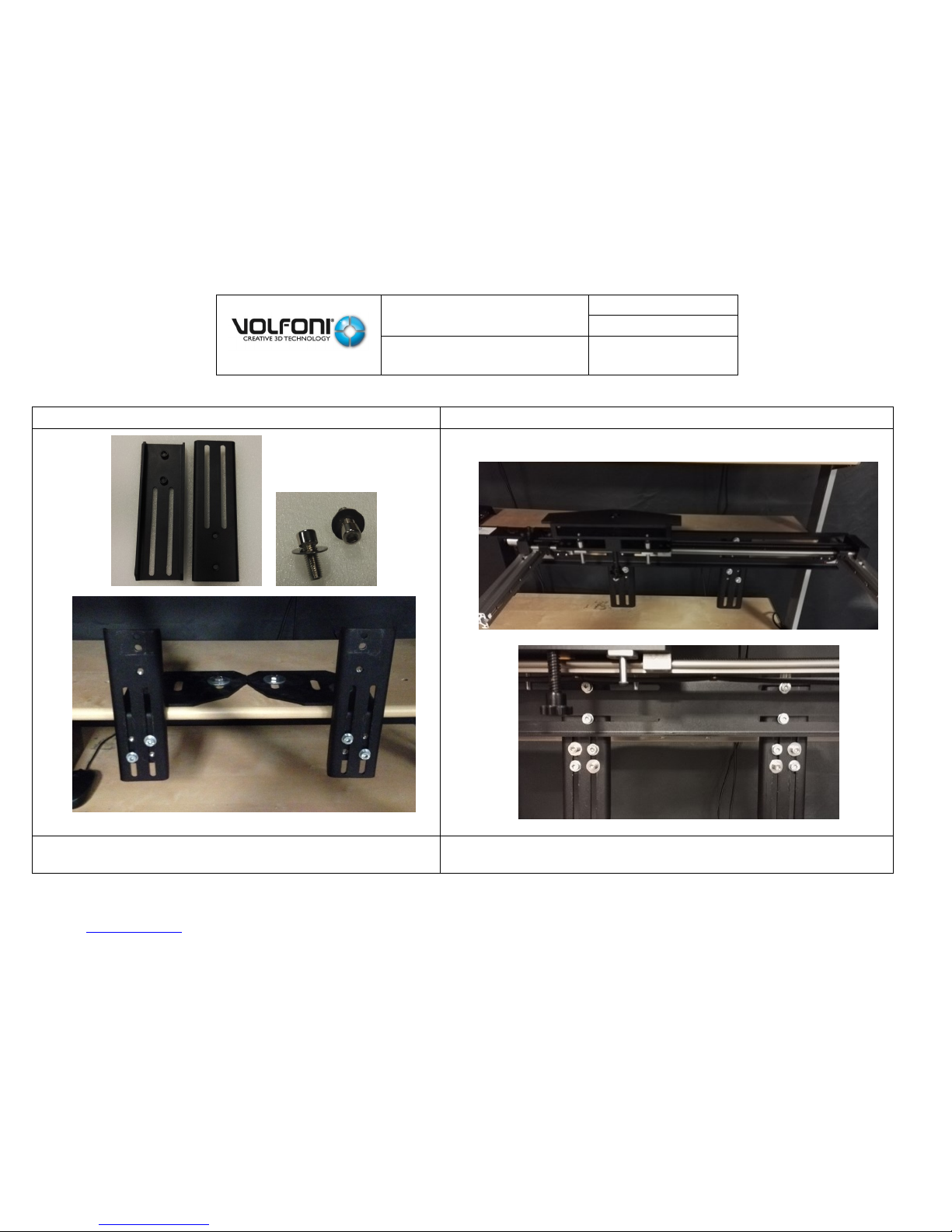
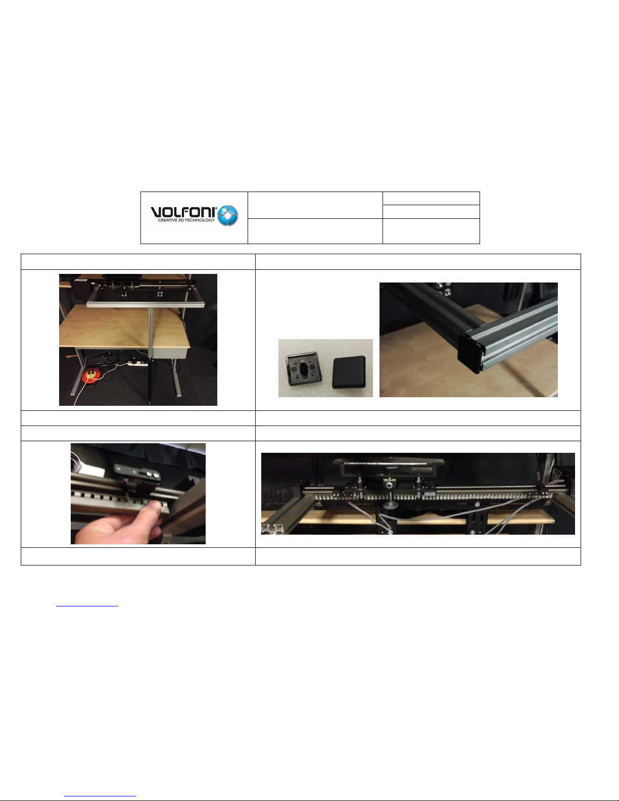
1. The bracket installation --------------------------------------------------------------------------------------------------------------------------------------------------------------------------- 19
The bracket’s elements and the different tools needed--------------------------------------------------------------------------------------------------------------------------------------- 20 a.
The bracket’s installation type ----------------------------------------------------------------------------------------------------------------------------------------------------------------------- 21 b.
The bracket installation -------------------------------------------------------------------------------------------------------------------------------------------------------------------------------- 21 c.
2. Assembly of the SmartCrystal™ Diamond box on the bracket and positioning in front of the projector -------------------------------------------------------------------- 31
3. The SmartCrystal™ Diamond box tilt adjustment and locking -------------------------------------------------------------------------------------------------------------------------- 34
4. 2-D/3-D position stops positioning ------------------------------------------------------------------------------------------------------------------------------------------------------------- 37
5. Electrical installation and projector settings ------------------------------------------------------------------------------------------------------------------------------------------------- 40
6. The SmartCrystal™ Diamond box Image adjustment -------------------------------------------------------------------------------------------------------------------------------------- 43
III.
ADDITIONAL ANTI-REFLECTION FILTER
------------------------------------------------------------------------------------------------------------------------------------------------------------- 58
1. Context ------------------------------------------------------------------------------------------------------------------------------------------------------------------------------------------------ 58
2. Filter assembly --------------------------------------------------------------------------------------------------------------------------------------------------------------------------------------- 58
IV.
SOFTWARE INTERFACE
--------------------------------------------------------------------------------------------------------------------------------------------------------------------------- 59
1. Introduction ------------------------------------------------------------------------------------------------------------------------------------------------------------------------------------------ 59
2. SCD software version ------------------------------------------------------------------------------------------------------------------------------------------------------------------------------ 59
3. Functioning modes, settings, other functions ----------------------------------------------------------------------------------------------------------------------------------------------- 60
V.
TROUBLES SHOOTING
---------------------------------------------------------------------------------------------------------------------------------------------------------------------------- 61
VI.
IMPORTANT SAFETY RECOMMENDATIONS
----------------------------------------------------------------------------------------------------------------------------------------------- 63
VII.
WARRANTY
------------------------------------------------------------------------------------------------------------------------------------------------------------------------------------------ 63
VIII.
FURTHER INFORMATION
------------------------------------------------------------------------------------------------------------------------------------------------------------------------ 63
IX.
REGULATORY STANDARDS
---------------------------------------------------------------------------------------------------------------------------------------------------------------------- 64

SmartCrystal™ Diamond
n ° : MUV140036
Version : A12
USER MANUAL
Date : 11/01/2018
www.volfoni.com This document is the property of the Co VOLFONI and may not be reproduced or disclosed without permission. 4
ANNEXE 01
------------------------------------------------------------------------------------------------------------------------------------------------------------------------------------------------- 65
VASP-09xxx SCD bracket installation
--------------------------------------------------------------------------------------------------------------------------------------------------------------- 65
ANNEXE 02
------------------------------------------------------------------------------------------------------------------------------------------------------------------------------------------------- 79
Mounting the bracket in the projector legs--------------------------------------------------------------------------------------------------------------------------------------------------------- 79
ANNEXE 03
------------------------------------------------------------------------------------------------------------------------------------------------------------------------------------------------- 83
Mounting the bracket in the projector bench ------------------------------------------------------------------------------------------------------------------------------------------------------ 83
ANNEXE 04
------------------------------------------------------------------------------------------------------------------------------------------------------------------------------------------------- 87
Mounting the desktop bracket ------------------------------------------------------------------------------------------------------------------------------------------------------------------------- 87
ANNEXE 05
------------------------------------------------------------------------------------------------------------------------------------------------------------------------------------------------- 89
Wall mounting solution ---------------------------------------------------------------------------------------------------------------------------------------------------------------------------------- 89
ANNEXE 06 -------------------------------------------------------------------------------------------------------------------------------------------------------------------------------------------------- 90
Precision and tilt adjustments ------------------------------------------------------------------------------------------------------------------------------------------------------------------------- 90
Height precision adjustment ----------------------------------------------------------------------------------------------------------------------------------------------------------------------------------- 90
ANNEXE 07
------------------------------------------------------------------------------------------------------------------------------------------------------------------------------------------------- 92
SCD bracket disengagement. --------------------------------------------------------------------------------------------------------------------------------------------------------------------------- 92
ANNEXE 08
------------------------------------------------------------------------------------------------------------------------------------------------------------------------------------------------- 94
SCD bracket disengagement for the models VASP-09XXX. ------------------------------------------------------------------------------------------------------------------------------------- 94

SmartCrystal™ Diamond
n ° : MUV140036
Version : A12
USER MANUAL
Date : 11/01/2018
www.volfoni.com This document is the property of the Co VOLFONI and may not be reproduced or disclosed without permission. 5
INTRODUCTION
General points a.
The SmartCrystal™ Diamond is the latest passive 3-D innovation offered by Volfoni.
The SmartCrystal™ Diamond is directly put in front of a 3-D projector lens. Combined with an appropriate screen (silvered screen), it
enables the audience wearing passive 3-D glasses to see in three dimensions.
The SmartCrystal™ Diamond technology offers a unique visual experience:
High light performance
Easy and quick installation: light and small-sized, it enables you to adapt to the variety and complexity of several configurations
such as ‘boothless’, and can be easily installed or uninstalled.
2-D/3-D configuration: The system is ideally designed to be assembled with a support which enables you to move it
manually/automatically according to the 2-D or 3-D projection mode.
Compatibility: The SmartCrystal™ Diamond works for DLP digital projectors offered by Christie, Barco, NEC. For every other
model, we invite you to contact Volfoni directly.
Contents of this manual b.
This manual is aimed at providing the SmartCrystal™ Diamond installation instructions and maintenance operations.
This manual has to be used while following the working and security rules of the projector, which are among other information
mentioned in the projector user manual.
Presentation of the SmartCrystal™ Diamond components
Installation and adjustment of the SmartCrystal™ Diamond Box
Installation and connection of the SmartCrystal™ Diamond Controller
Transition from 2-D to 3-D mode and conversely
Maintenance
This manual is meant for fitters who are entitled to install the SmartCrystal™ Diamond. The use of this manual implies that the cinema’s
equipment respects all the 3-D screening necessary conditions such as the lamp type, the silvered screen or the glasses type.
This manual is exclusively meant for professionals who are authorized to operate on screening systems in cinema projection rooms.
Skilled technicians only, who are aware of potential dangers associated with high voltage, ultraviolet exposure and high
temperatures generated by lamps and their power circuit, are authorized to install/de-install the SmartCrystal™ Diamond and to
service it.

SmartCrystal™ Diamond
n ° : MUV140036
Version : A12
USER MANUAL
Date : 11/01/2018
www.volfoni.com This document is the property of the Co VOLFONI and may not be reproduced or disclosed without permission. 6
Specification of the projector c.
The SmartCrystal™ Diamond is used with digital cinema projectors. It has been designed to work with the various digital cinema
projectors developed by the main manufacturers using the Texas Instrument DLP® technology.
This manual is based on the assumption that all of the specifications for the installation of the projector have been respected and
that the projector is ready for use. This manual has to be used while respecting the instructions for the installation of your system,
among them the projector’s user guide.
Specification of the bracket d.
The SmartCrystal™ Diamond is assembled on a specific bracket.
This manual is based on the assumption that all the specifications for the installation of the bracket have been respected and that
the bracket is ready for use. This manual has to be used while respecting the installation instructions of your system, among them the
bracket user guide.
Volfoni passive glasses e.
With the SmartCrystal™ Diamond, the audience is required to wear passive glasses with circular polarization to watch 3-D contents.
Volfoni offers passive glasses with circular polarization which are optimized for a better quality 3-D visual experience.
These glasses are disposable or washable under the conditions recommended by Volfoni.
The polarizer filters of the glasses need to be compatible with the polarization generated by the SmartCrystal™ Diamond.
WARNING
THE CINEMA PASSIVE GLASSES MUST NOT BE USED AS SUNGLASSES.
POLARIZER FILTERS CANNOT PROTECT FROM ULTRAVIOLETS.
SmartCrystal™ Diamond
n ° : MUV140036
Version : A12
USER MANUAL
Date : 11/01/2018
www.volfoni.com This document is the property of the Co VOLFONI and may not be reproduced or disclosed without permission. 7
I. GENERAL PRESENTATION
1.
SmartCrystal™ Diamond (SCD) presentation
Each SmartCrystal™ Diamond is made up by the following components:
SmartCrystal™ Diamond Box (opto-mechanical unit)
SmartCrystal™ Diamond Controller (electronic unit)
One set of 3-D bus cables (GPIO37-BNC, SubD15-BNC, BNC-BNC),
Connection cable between SCD Box and SCD Controller (SubD9 M/F),
Feeder cable (220/110V) with US, EU, UK, AUS plugs.
Software maintenance cable (USB A-USB B)
Volfoni passive glasses (2 pairs)
Optional anti-reflection filter for room window
USB key with aligning pattern and technical data
Tools, holding screws
Cleaning wipe
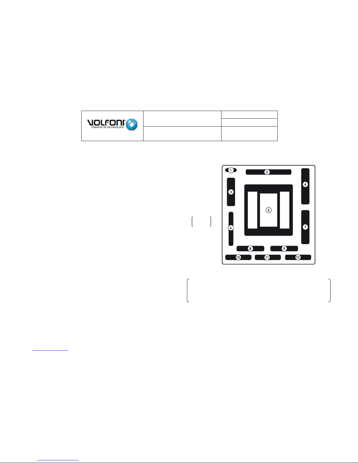
Quick Start
1- USB Key + Wipes (x2)
2- RJ45 Cable (Used for network control)
3- USB-A / USB-B (cable for maintenance with Volfoni Software)
4- SmartCrystal Diamond Controller
5- SmartCrystal Diamond System
6- Polarization Filter Optional filter. (Only use in case of abnormal reflections)
7- SUB-D 9pts Dedicated to connect SCD Controller and SCD System
8- GPIO-15 pins & BNC / BNC ( Cables 3D Synchronization cable)
9- Passive glasses VPPG-03000 (x2)
10- GPIO-37 pins Cable 3D Synchronization cable
11- International plugs (EU, US, AUS, China, and UK)
12- Power supply for the SCD Controller
Each SmartCrystal™ Diamond will be delivered
with a bracket which must be installed while
respecting the instructions of its user guide.
Fig 01
SmartCrystal™ Diamond
n ° : MUV140036
Version : A12
USER MANUAL
Date : 11/01/2018
www.volfoni.com This document is the property of the Co VOLFONI and may not be reproduced or disclosed without permission. 8
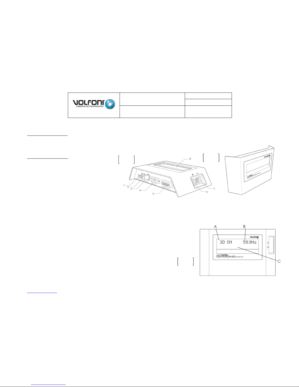
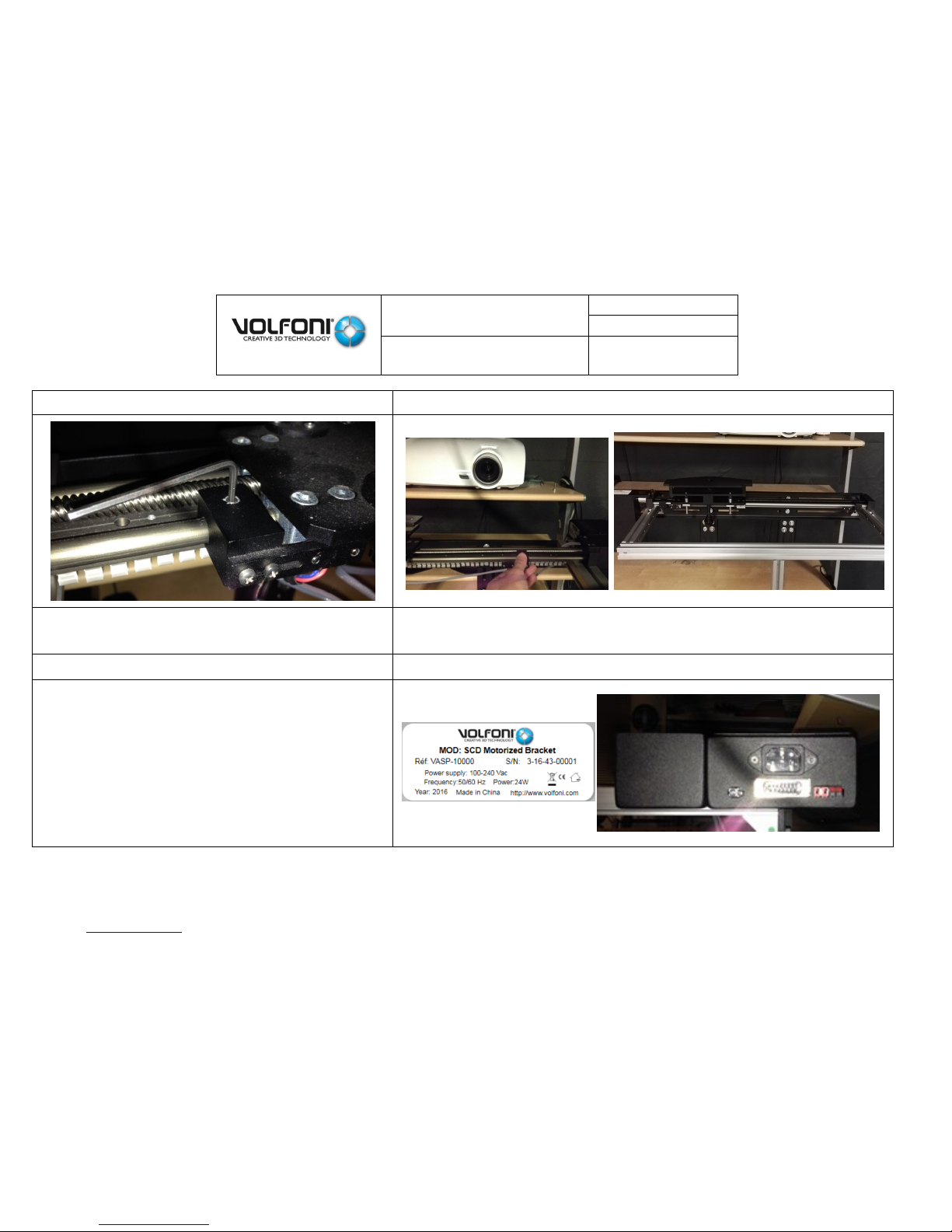
The SmartCrystal™ Diamond Box a.
General introduction
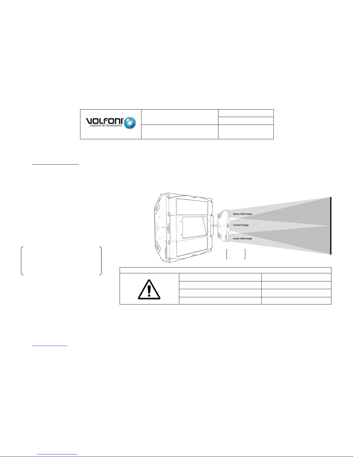
The SmartCrystal™ Diamond Box is the opto-mechanical unit.
The SmartCrystal™ Diamond technology splits up the incident light flux into three separate fluxes:
The central flux (full image)
The upper flux (upper half image)
The lower flux (lower half image)
If you want to switch two electronic boxes, you must respect this compatibility table:
SCD CONTROLLER (Electronic box)
SCD (Optical box)
VSSP ≥ 10200
VSSP ≥ 13300
VSSP-10100
VSSP ≤ 13200
VSSP-10000
VSSP ≤ 13200
The system adjustment consists in
perfectly recombining these
three fluxes on the screen into a
single image (see right).
Fig 02
SmartCrystal™ Diamond
n ° : MUV140036
Version : A12
USER MANUAL
Date : 11/01/2018
www.volfoni.com This document is the property of the Co VOLFONI and may not be reproduced or disclosed without permission. 9
Detailed presentation
The SmartCrystal Diamond Box is compact and light:
Dimensions: W 28 cm X H 26 cm X D 10 cm
Weight: about 6kg.
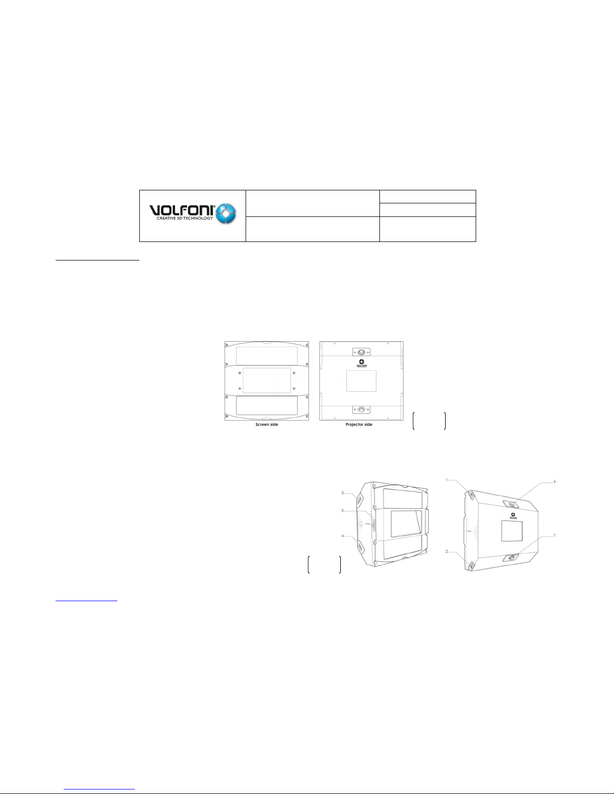
On one side, the ‘screen’ side of the SmartCrystal™ Diamond Box is made up of the three outflow windows.
On the other side, the ‘projector’ side is made up of the entry window of the SmartCrystal™ Diamond Box, so as of two wheels to
adjust the system (see below).
On both sides (left and right) of the SmartCrystal™ Diamond Box are fitting wheels for the upper and lower half images. They enable
you to adjust the position of the two half images vertically and horizontally.
They are completed with two zoom wheels located on the projector side of the device. All of these six wheels are used to
align/superimpose the two half images on the central image.
1) Upper half image left/right adjustment wheel
2) Lower half image left/right adjustment wheel
3) Upper half image up/down adjustment wheel
4) Lower half image up/down adjustment wheel
5) Connector of the SmartCrystal™ Diamond box (SubD-9)
6) Upper half image +/- zoom wheel
7) Lower half image +/- zoom wheel
Fig 03
Fig 04
SmartCrystal™ Diamond
n ° : MUV140036
Version : A12
USER MANUAL
Date : 11/01/2018
www.volfoni.com This document is the property of the Co VOLFONI and may not be reproduced or disclosed without permission. 10
SmartCrystal™ Diamond Controller b.
General presentation
The SmartCrystal™ Diamond Controller is the electronic unit of the system. Figure 6 shows a general
view of the SmartCrystal™ Diamond Controller.
Detailed presentation
1) Automation – pluggable terminal block connector (3
points): It enables you to control the system
automatically with ‘hit or miss’ electrical entries.
2) Network Operating Center (NOC) - RJ45 connector: It
enables you to run and to interact with the system from
a remote/relocated computer center.
3) Sync_3D – BNC connector: Synchronization signal
generated by the projector or another source.
4) SCD Box interface - SUBD9 connector: This interface is
used to run the SCD Box.
5) Bracket-connector SUBD15 interfaces: This duplex interface is used to interact with the bracket and to run it to automate 2-D/3-D modes.
6) Feeding of the SmartCrystal™ Diamond Controller. This entry must be always used with the external feeding (5V/1.5A)
7) Maintenance – USB connector: Entry designed for SmartCrystal™ Diamond Controller software maintenance.
8) Digital information area about the system state and functioning.
B
The following Figure is a view of the SmartCrystal™ Diamond Controller digital display.
The screen displays:
A: The current working mode: 2-D or 3-D.
B: The vision frequency received by the system through the SYNC_3D entry.
C: Other information about the system: bracket state etc.
Fig 05
Fig 06
Fig 07
SmartCrystal™ Diamond
n ° : MUV140036
Version : A12
USER MANUAL
Date : 11/01/2018
www.volfoni.com This document is the property of the Co VOLFONI and may not be reproduced or disclosed without permission. 11
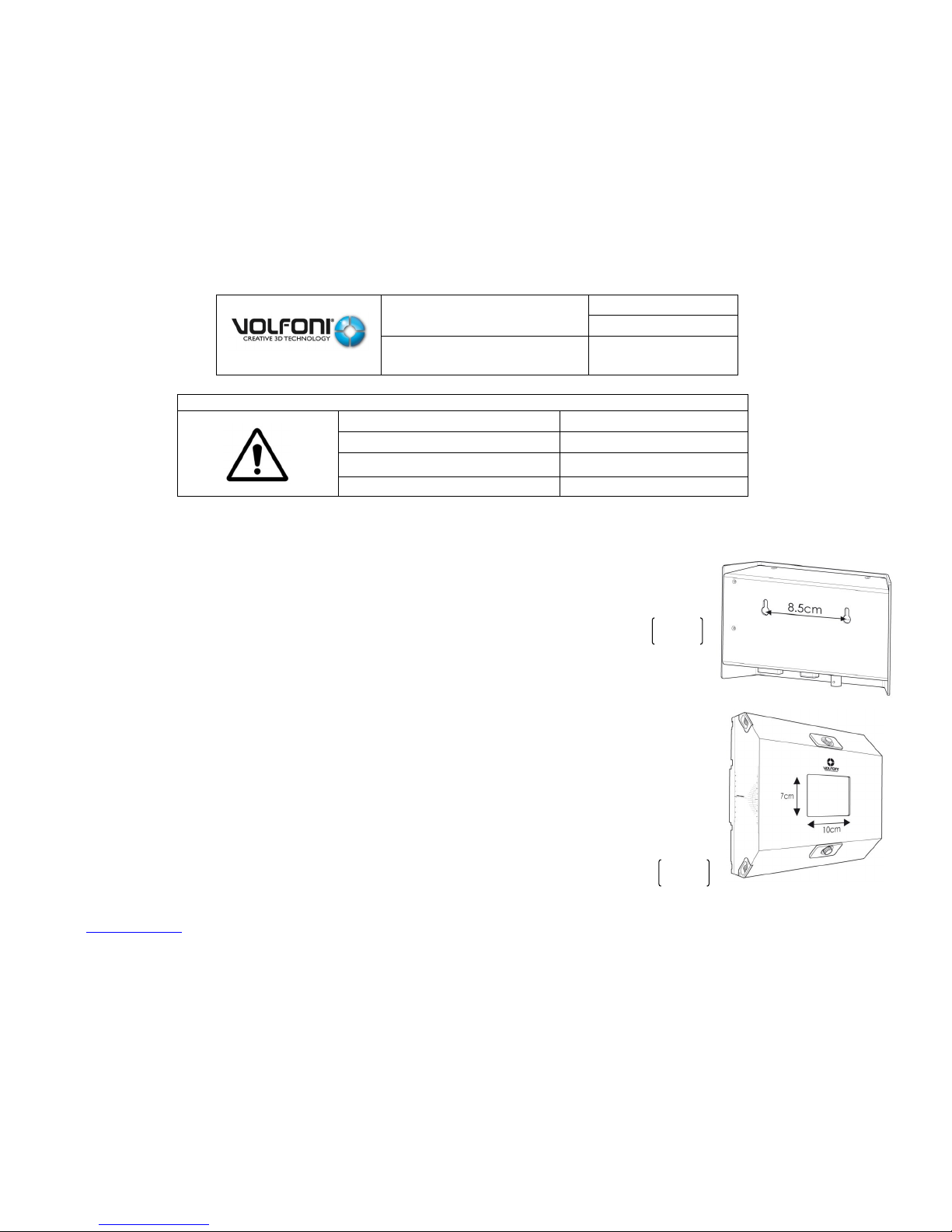
The SCD Controller can be fixed using the perforations located on the back of the box (Fig 07).
The distance between these two mounting points is 8,5 cm.
2.
Requirements and important recommendations to install the SmartCrystal™
Diamond
IT IS ABSOLUTELY ESSENTIAL TO MEET THE FOLLOWING CRITERIA TO INSTALL THE SMARTCRYSTAL™
DIAMOND BOX.
Room configuration a.
Minimum size of the room window: 40cm X 40 cm
Such an outflow image of the SmartCrystal™ Diamond Box requires that the size of the room
window must be at least 40cm x 40cm if the ‘screen’ side of the system stands at less than 10cm
from this window.
If you want to switch two electronic boxes, you must respect this compatibility table:
SCD CONTROLLER (Electronic box)
SCD (Optical box)
VSSP ≥ 10200
VSSP ≥ 13300
VSSP-10100
VSSP ≤ 13200
VSSP-10000
VSSP ≤ 13200
Fig 08
Fig 09
SmartCrystal™ Diamond
n ° : MUV140036
Version : A12
USER MANUAL
Date : 11/01/2018
www.volfoni.com This document is the property of the Co VOLFONI and may not be reproduced or disclosed without permission. 12
The farther the device will be positioned from the room window, the larger the size of this latter should be. Do not hesitate to contact
your supplier for any technical support.
Image centering on the window
The projector has to be installed so that the image is centered to the room window, requirement all the more important if the latter is
minimum-sized (40cm X 40cm).
The projection room window must not depolarize light.
The image size at 2cm from the lens must not exceed 10 cm X 7 cm. This size corresponds to the size of the SmartCrystal™ Diamond
Box inflow window.
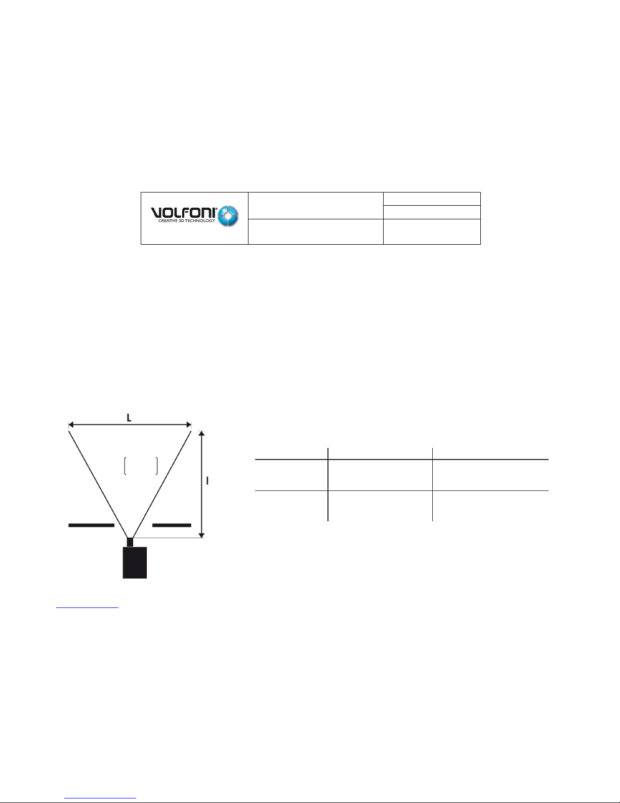
Film theatre configuration: ‘Throw Ratio’ of the cinema b.
Before any installation, making sure that the device is compatible with the theatre is important. The ‘Throw Ratio’ (TR) enables a first
assessment.
If the projector outflow image meets the previous requirements (*), the ‘Throw Ratios’ to respect
are the following:
(*) : The SmartCrystal™ Diamond Box must be situated as close as possible to the lens, i.e. less than 2cm.
TR = (Distance between projector and screen => l) / (screen width => L)
THROW
Config Flat - 1.85
Config Scope - 2.39
DLP 1.2’’
PROJECTOR
TR >= 1.35
TR >= 1.2
DLP 0.98’’
PROJECTOR
TR >= 1.30
TR >= 1.2
Fig 10
SmartCrystal™ Diamond
n ° : MUV140036
Version : A12
USER MANUAL
Date : 11/01/2018
www.volfoni.com This document is the property of the Co VOLFONI and may not be reproduced or disclosed without permission. 13
3. SmartCrystal™ Diamond bracket presentation (VASP-10xxx)
WARNING: for the previous generation of bracket (VASP-09XXX) please refer to the ANNEXE 01 below.
The SmartCrystal™ Diamond bracket a.
The SmartCrystal™ Diamond Box must be assembled with a bracket which enables you to fit its position opposite the projector with
high precision: Height, angle, distance from the projector (i.e. projector lens) and lateral movement for the 2D/3D modes.
WARNING
To avoid any damage to projector lens:
- The bracket has to be correctly fixed on the table or on the
wall
- The product can move along the slide in both directions
without touching the lens
Volfoni provides the bracket to position the SmartCrystal™
Diamond Box properly in front of the projector lens.
For assembling instructions, please refer to the bracket user
guide. It contains the possible assembly drawings
depending on the various configurations.
Fig 11
SmartCrystal™ Diamond
n ° : MUV140036
Version : A12
USER MANUAL
Date : 11/01/2018
www.volfoni.com This document is the property of the Co VOLFONI and may not be reproduced or disclosed without permission. 14
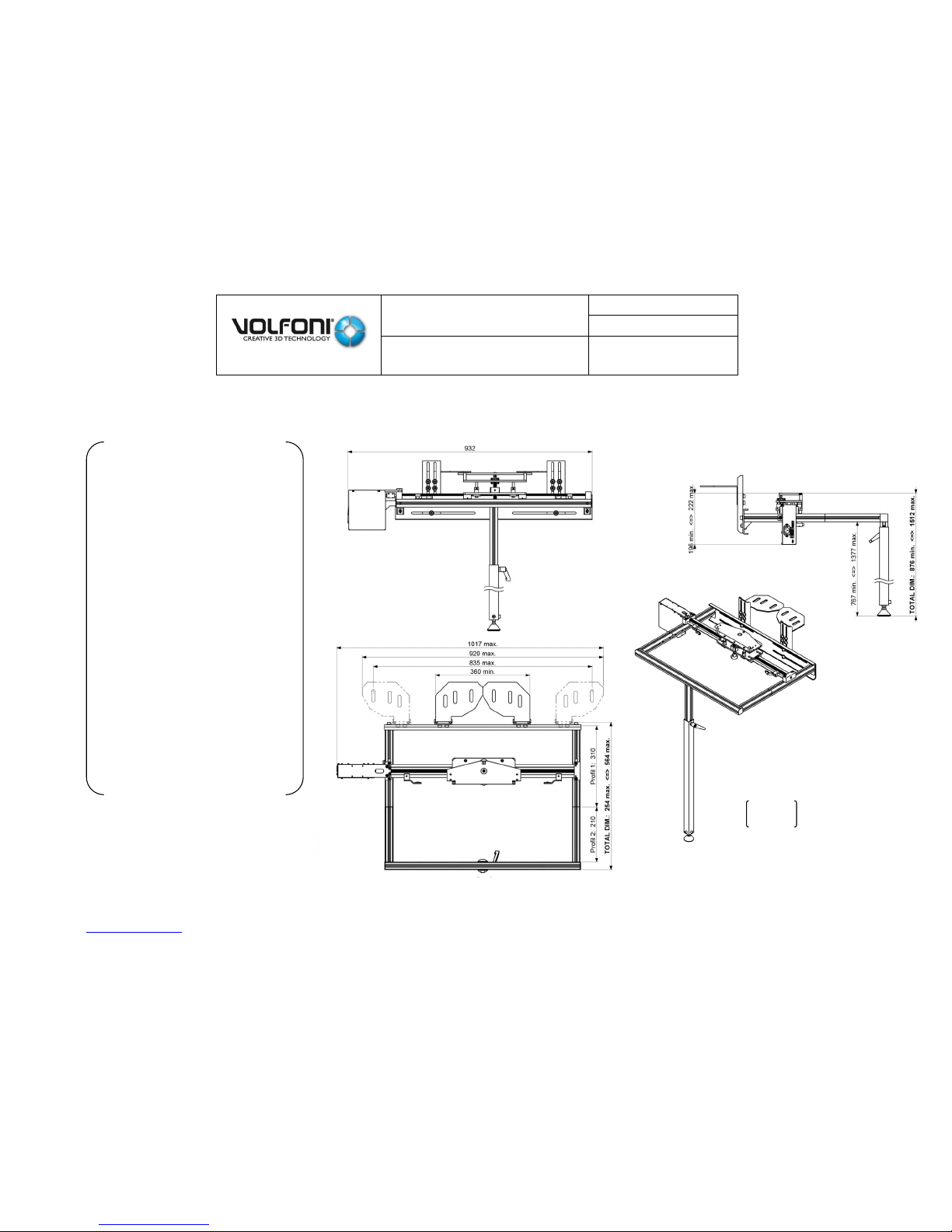
The technical Specifications b.
DIMENSIONS: 900 x 310 x
150mm
NET WEIGHT: 13 kg
PACKING DIMENSIONS
: 1000 x 370 x 250mm
GROSS WEIGHT : 14
kg.
FINISH IN : Aluminum
powder coating
COLOR: Aluminum Grey
and black
TILT RANGE: 15°
MAX. HIGH ADJUSTMENT
TABLE OPTION: 145 mm +
22 mm
BENCH OPTION: 208 mm +
30 mm
HIGH PRECISION
ADJUSTMENT +/- 30 mm
HORIZONTAL ADJUSTMENT
CURSE: 250 mm + 200 mm
Fig 12
SmartCrystal™ Diamond
n ° : MUV140036
Version : A12
USER MANUAL
Date : 11/01/2018
www.volfoni.com This document is the property of the Co VOLFONI and may not be reproduced or disclosed without permission. 15
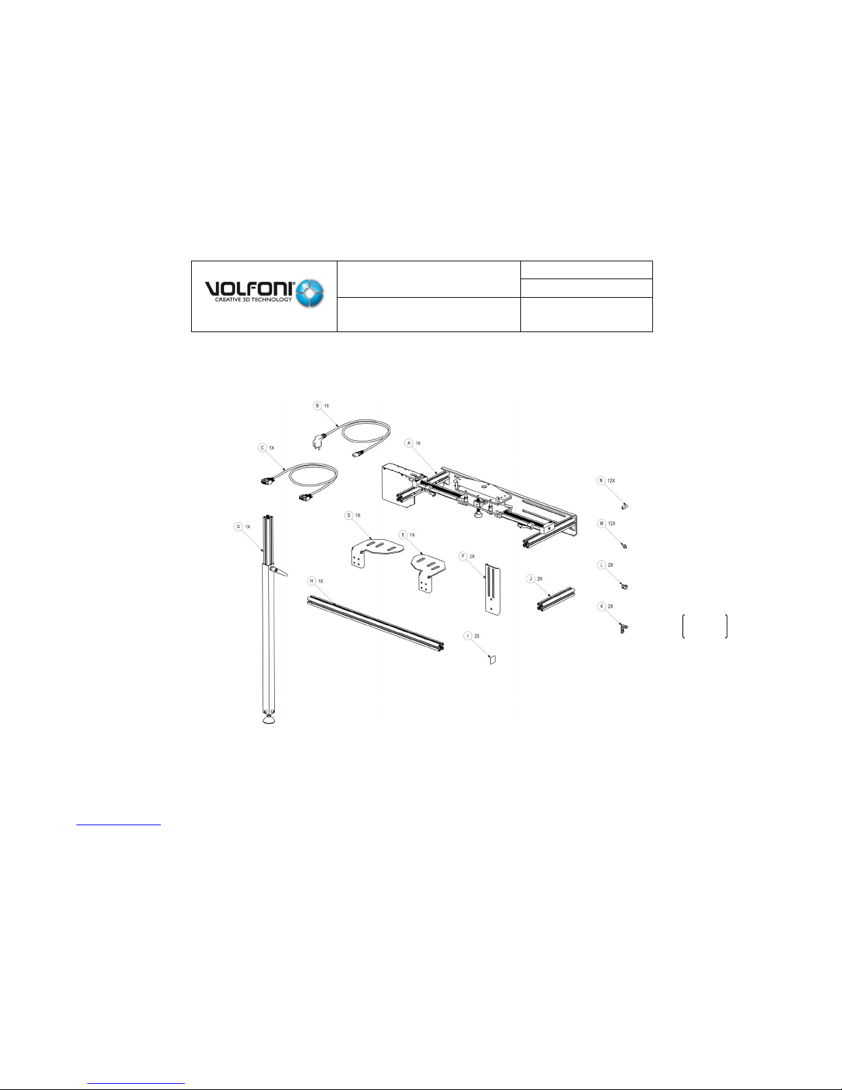
List of accessories c.
The kit includes all necessary accessories for mounting the support in all possible ways. It also includes the necessary screws.
The bracket is included in the KIT to assembly on site. Main parts are already assembled.
The packing includes a set of Allen wrenches to mount the bracket (2mm – 2.5mm – 3mm – 4mm – 5mm)
Fig 13
SmartCrystal™ Diamond
n ° : MUV140036
Version : A12
USER MANUAL
Date : 11/01/2018
www.volfoni.com This document is the property of the Co VOLFONI and may not be reproduced or disclosed without permission. 16
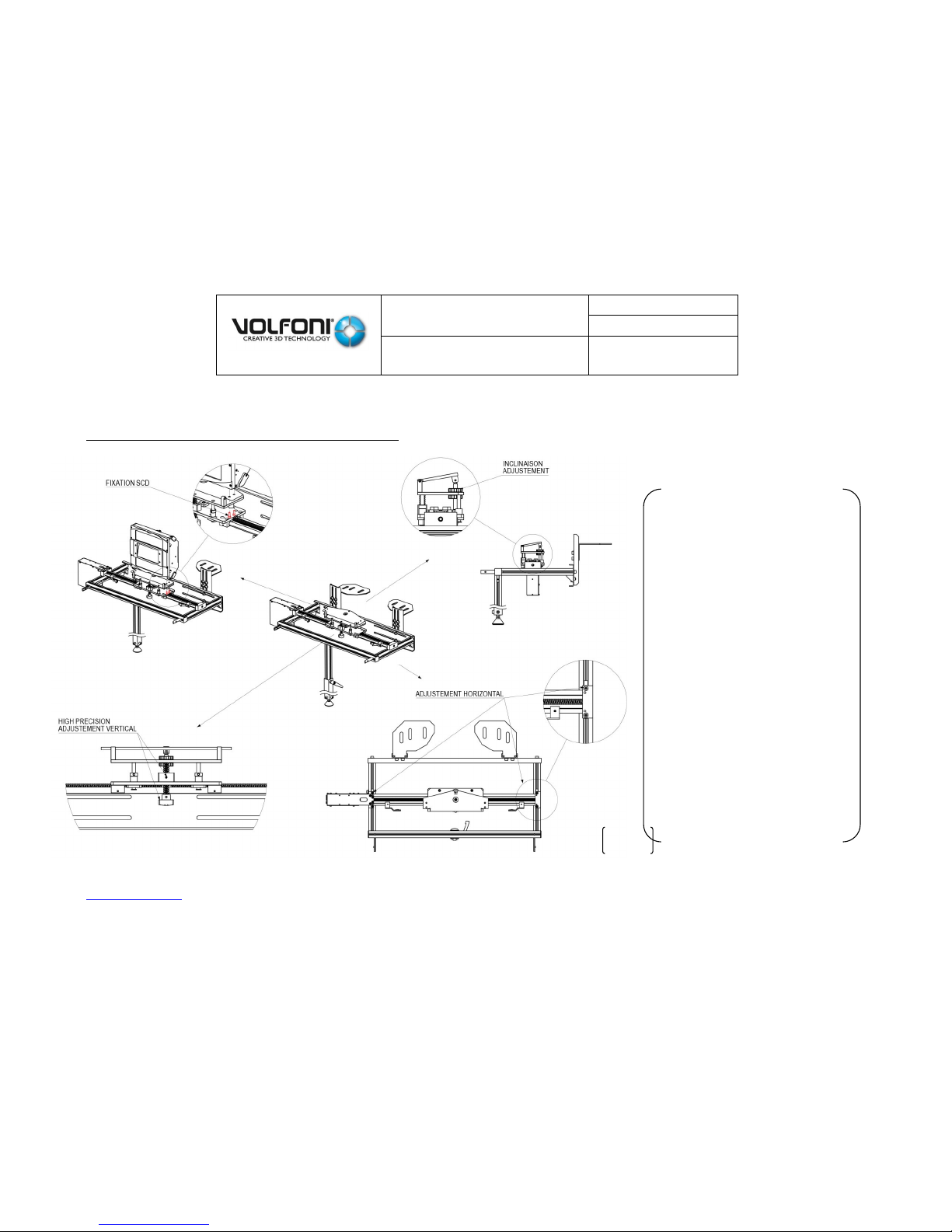
Mounting of the bracket overview d.
Installation and adjustment on the support overview
Several steps to
install the SCD on
the Bracket
- Fixing the SCD on
the support with 4
screws.
- Adjustment of the
Horizontal position.
SCD must be as
closed as possible
to the lens of the
projector
- Adjustment of the
vertical position:
Beam light should
enter in the center
of the entrance
windows of the
SCD.
- Adjustment of the
SCD angle
Fig 14
SmartCrystal™ Diamond
n ° : MUV140036
Version : A12
USER MANUAL
Date : 11/01/2018
www.volfoni.com This document is the property of the Co VOLFONI and may not be reproduced or disclosed without permission. 17
Setting 2D and 3D position
The bracket has two sensors to
define 2D and 3D position. The
position of theses sensors must
be adjusted depending on
the position of the lens and will
define the limits of the SCD
displacement.
SmartCrystal™ Diamond
n ° : MUV140036
Version : A12
USER MANUAL
Date : 11/01/2018
www.volfoni.com This document is the property of the Co VOLFONI and may not be reproduced or disclosed without permission. 18
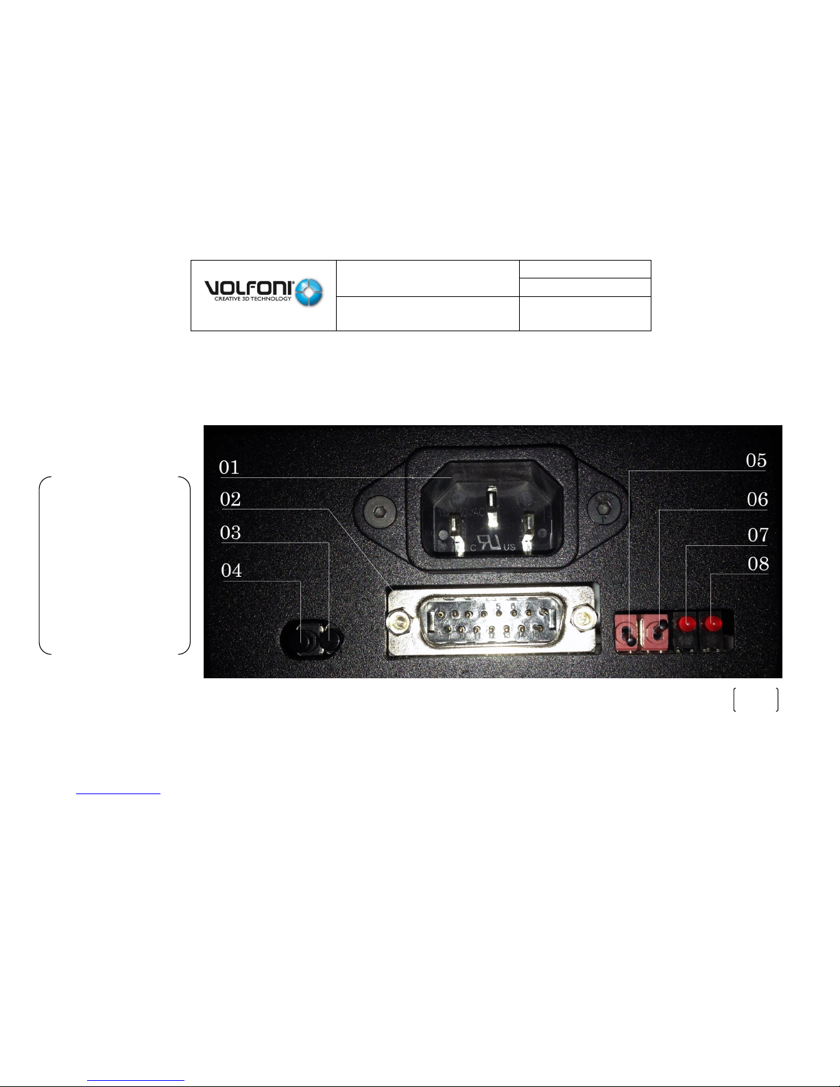
Appendix e.
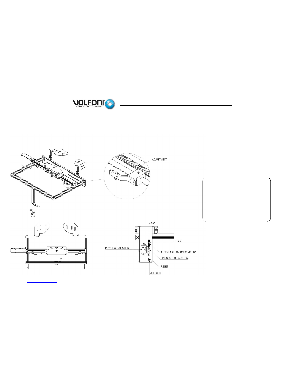
Status LED, status settings & electrical wiring
(01) Power Outlet
(02) Link Control
(03) Reset
(04) Not used
(05) 2D / 3D Position
(06) BRACKET OK /
BRACKET UNREADY
(07) +12VDC
(08) +5VDC
Fig 16
SmartCrystal™ Diamond
n ° : MUV140036
Version : A12
USER MANUAL
Date : 11/01/2018
www.volfoni.com This document is the property of the Co VOLFONI and may not be reproduced or disclosed without permission. 19
II. INSTALLATION OF THE SMARTCRYSTAL DIAMOND
IT IS ABSOLUTELY ESSENTIAL TO FOLLOW CLOSELY ALL THE STEPS
1. The bracket installation
When installing the bracket it is
important to keep in mind the
goal is the following
- The upper plate of the bracket must be
pre-positioned 13cm far from the beam
center, so as in the figure right
- The upper plate of the bracket must be
pre-positioned 2cm far from the lens, so
as in the figure right
Before installing anything we
invite you to do the
measurements to have an idea
where the upper will be. It will
help you to visualize your goal
and make the right decisions
Fig 17
SmartCrystal™ Diamond
n ° : MUV140036
Version : A12
USER MANUAL
Date : 11/01/2018
www.volfoni.com This document is the property of the Co VOLFONI and may not be reproduced or disclosed without permission. 20
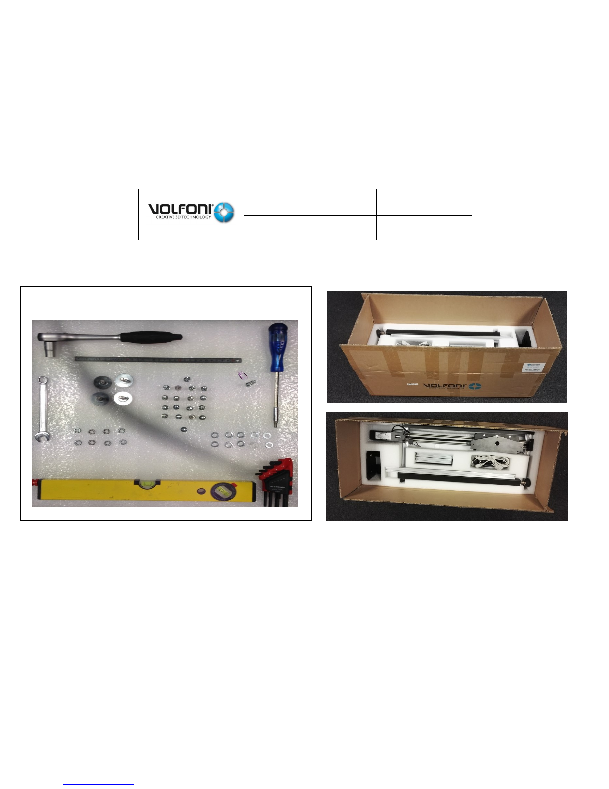
The bracket’s elements and the different tools needed a.
The necessary tools
SmartCrystal™ Diamond
n ° : MUV140036
Version : A12
USER MANUAL
Date : 11/01/2018
www.volfoni.com This document is the property of the Co VOLFONI and may not be reproduced or disclosed without permission. 21
The bracket’s installation type b.
We have chosen to focus on the most common installation type: Mounting the bracket in the projector bench. You will find others
way to install the bracket below. Please have a look before starting the installation
ANNEXE 02 => Mounting the bracket in the projector legs
ANNEXE 03 => Mounting the bracket in the projector bench
ANNEXE 04 => Mounting the desktop bracket
ANNEXE 05 => Wall mounting solution
The bracket installation c.
STEP 01
STEP 02
Choose your configuration => ANNEXE 02 to 05
Bracket Maximum distance
Minimum height
Depending on your configuration
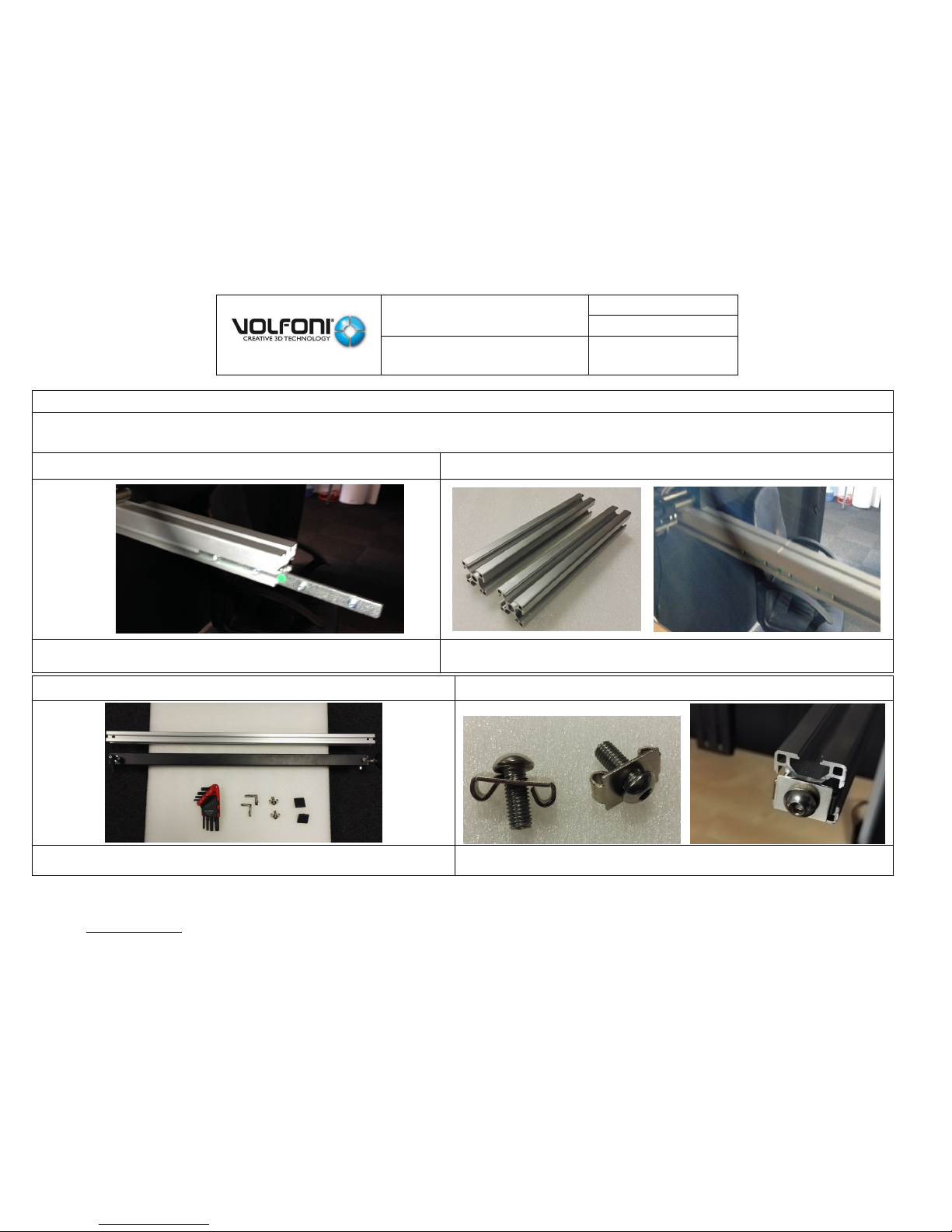
Fix D & E parts
SmartCrystal™ Diamond
n ° : MUV140036
Version : A12
USER MANUAL
Date : 11/01/2018
www.volfoni.com This document is the property of the Co VOLFONI and may not be reproduced or disclosed without permission. 22
STEP 03
STEP 04
Fix F parts using 8 units of M and N pieces
Fix A part using 4 units of M and N pieces
SmartCrystal™ Diamond
n ° : MUV140036
Version : A12
USER MANUAL
Date : 11/01/2018
www.volfoni.com This document is the property of the Co VOLFONI and may not be reproduced or disclosed without permission. 23
STEP 05
If the length of the projector’s lens is more than 15 centimeters
Please follow the procedure if not please go directly to the STEP 08
STEP 06
STEP 07
Positioning connecting bars on each side of J parts
Fix the 4 screws to lock A and J part.
The same operation has to be done on the other side of the bracket.
STEP 08
STEP 09
Bracket feet installation : Parts & tools
Screw L pieces on J parts
SmartCrystal™ Diamond
n ° : MUV140036
Version : A12
USER MANUAL
Date : 11/01/2018
www.volfoni.com This document is the property of the Co VOLFONI and may not be reproduced or disclosed without permission. 24
STEP 10
STEP 11
Use H part
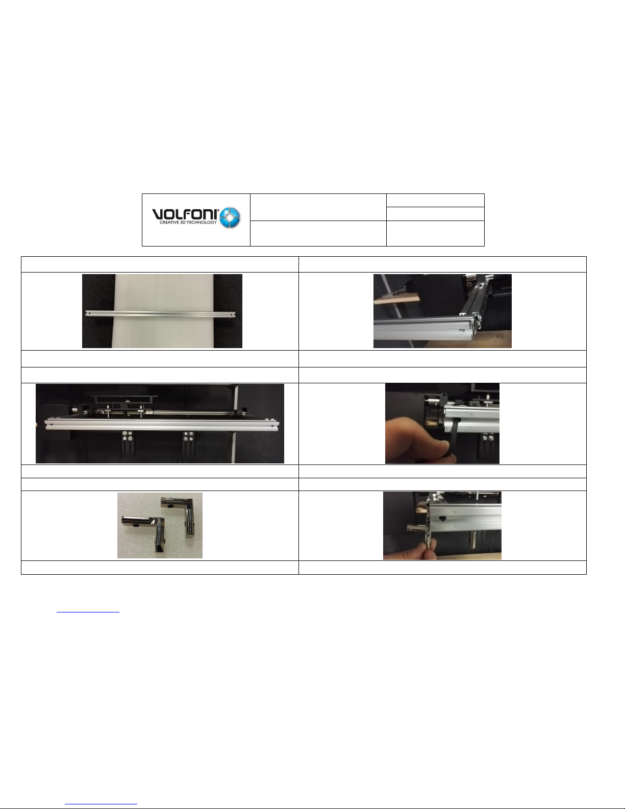
Slide the H part on the end of J parts
STEP 12
STEP 13
Put the H part with the L screws in front of the holes
Fix them together with the Allen key
STEP 14
STEP 15
Use the K parts
Slide them in the H part
SmartCrystal™ Diamond
n ° : MUV140036
Version : A12
USER MANUAL
Date : 11/01/2018
www.volfoni.com This document is the property of the Co VOLFONI and may not be reproduced or disclosed without permission. 25
STEP 16
STEP 17
Put the K parts in the middle of the H part
Use the G part
STEP 18
STEP 19
Put H part and G part together
Once positioned, fit the screws of K parts
SmartCrystal™ Diamond
n ° : MUV140036
Version : A12
USER MANUAL
Date : 11/01/2018
www.volfoni.com This document is the property of the Co VOLFONI and may not be reproduced or disclosed without permission. 26
STEP 20
STEP 21
Adjust the height of the G part
Add the I pieces at the end of H part
STEP 22
STEP 23
Remove fixations for sensor limit cables
Remove the 2 bracket position sensors wires from guide
SmartCrystal™ Diamond
n ° : MUV140036
Version : A12
USER MANUAL
Date : 11/01/2018
www.volfoni.com This document is the property of the Co VOLFONI and may not be reproduced or disclosed without permission. 27
STEP 24
STEP 25
Unscrew 2 bracket position sensors
In this configuration, move right position sensor from its position till a
position that will allow to put bracket upper plate face to projector
STEP 26
STEP 27
General view of the bracket electronic
1st button : Not used
2nd button : Reset button
1st contact : Motor command
2nd contact : Set 2D / 3D position
1st led : 12V
2nd led : 5V
SmartCrystal™ Diamond
n ° : MUV140036
Version : A12
USER MANUAL
Date : 11/01/2018
www.volfoni.com This document is the property of the Co VOLFONI and may not be reproduced or disclosed without permission. 28
STEP 28
STEP 29
Power on bracket and check 2 leds red
Bracket upper plate is at 2D position
STEP 30
STEP 31
Use first contact
Bracket will move and will stop face to bracket position sensor.
The bracket upper plate will be approximately face to projector
SmartCrystal™ Diamond
n ° : MUV140036
Version : A12
USER MANUAL
Date : 11/01/2018
www.volfoni.com This document is the property of the Co VOLFONI and may not be reproduced or disclosed without permission. 29
STEP 32
STEP 33
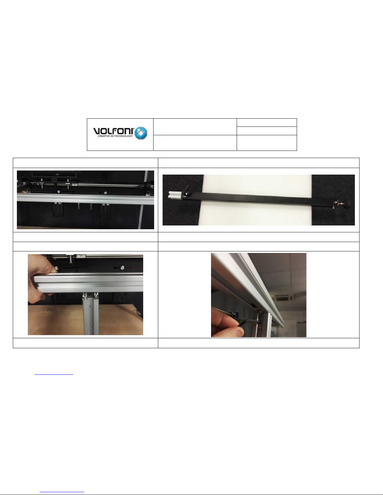
Unscrew and move the sensor limit to place the
bracket upper plate
Position the sensor limit to have the bracket upper plate
perfectly in front of the projector
STEP 34
STEP 35
Unscrew 2 screws of the rings on both side of the trolley
Loosen stud bolt of the trolley

SmartCrystal™ Diamond
n ° : MUV140036
Version : A12
USER MANUAL
Date : 11/01/2018
www.volfoni.com This document is the property of the Co VOLFONI and may not be reproduced or disclosed without permission. 30
STEP 36
STEP 37
Set bracket upper plate at middle position
Set bracket tilt at 0°
Check distance between bracket upper plate and middle of
projector lens. Right distance should be approximately 13cm
STEP 38
STEP 39
In case of bracket upper plate too high or too low
Readjust its position by modifying F parts position
Check horizontality is good

SmartCrystal™ Diamond
n ° : MUV140036
Version : A12
USER MANUAL
Date : 11/01/2018
www.volfoni.com This document is the property of the Co VOLFONI and may not be reproduced or disclosed without permission. 31
2. Assembly of the SmartCrystal™ Diamond box on the bracket and positioning in
front of the projector
The purpose of this step is to assemble the SCD Box with the bracket and to make sure there is no risk
of contact with the projector and its lens.
Position the carriage as far as possible from the projector lens in order to avoid any risk of
contact with this latter during the assembly of the SmartCrystal™ Diamond Box on the carriage.
Assemble the SmartCrystal™ Diamond with the bracket carriage.
After positioning the SmartCrystal™ Diamond Box, fix it on the carriage using 4 screws.
The screws and the wrench are provided with the system (see packing list).
As the SmartCrystal™ Diamond Box is properly fixed on the carriage, make the carriage slide and check the absence of
contact with the projector and its lens. In case of contact, fit the bracket adjustment to eliminate any risk of contact.
STEP 40
STEP 41
In the next step we will mount the SCD on
the bracket. Before be sure that the
trolley of the bracket is far away enough
from the lens of the projector
Unscrew the 2 screws on the both side of the endless screw
Fig 18

SmartCrystal™ Diamond
n ° : MUV140036
Version : A12
USER MANUAL
Date : 11/01/2018
www.volfoni.com This document is the property of the Co VOLFONI and may not be reproduced or disclosed without permission. 32
STEP 42
STEP 43
Move bracket in order SCD entrance windows will be
at approximately 2cm from projector lens
Check and adjust bracket position (same distance for both
side). SCD will be at approximately 2cm from projector lens
STEP 44
STEP 45
Screw the 2 screws on the both side of the endless screw
In this case the Bracket is at 3D position

SmartCrystal™ Diamond
n ° : MUV140036
Version : A12
USER MANUAL
Date : 11/01/2018
www.volfoni.com This document is the property of the Co VOLFONI and may not be reproduced or disclosed without permission. 33
STEP 46
STEP 47
Use first contact. SCD will reach automatically 2D position
Use a white pattern. Move slightly 3D bracket position sensor. The
SCD will follow the sensor until you obtain a maximum of light on
the side of the SCD

SmartCrystal™ Diamond
n ° : MUV140036
Version : A12
USER MANUAL
Date : 11/01/2018
www.volfoni.com This document is the property of the Co VOLFONI and may not be reproduced or disclosed without permission. 34
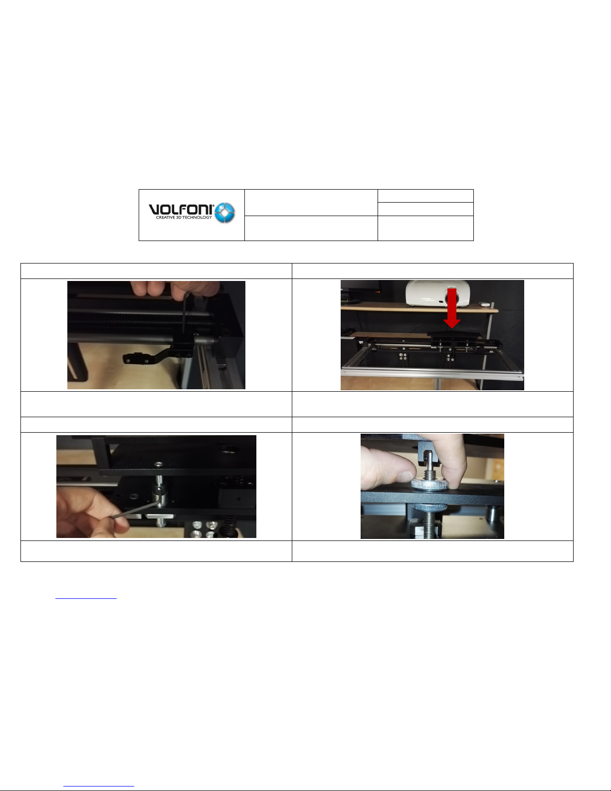
3. The SmartCrystal™ Diamond box tilt adjustment and locking
STEP 48
Adjustment of the SmartCrystal™ Diamond Box position
The purpose of this step is to position the SCD Box properly towards the
light coming from the projector.
• Make the carriage slide so that the beam of light from the projector
lights up the side of the SmartCrystal™ Diamond Box
(See Fig 19which shows a view from above).
This process can be carried out using the left side or the right side of the
SmartCrystal™ Diamond box.
Move 3D bracket position sensor until you obtain a maximum of light on the side of the SCD
STEP 49
By having a look on “Center alignment”
Adjust bracket height
Adjust bracket tilt
Image input has to be well centered
Image output has to be well centered
Fig 19

SmartCrystal™ Diamond
n ° : MUV140036
Version : A12
USER MANUAL
Date : 11/01/2018
www.volfoni.com This document is the property of the Co VOLFONI and may not be reproduced or disclosed without permission. 35
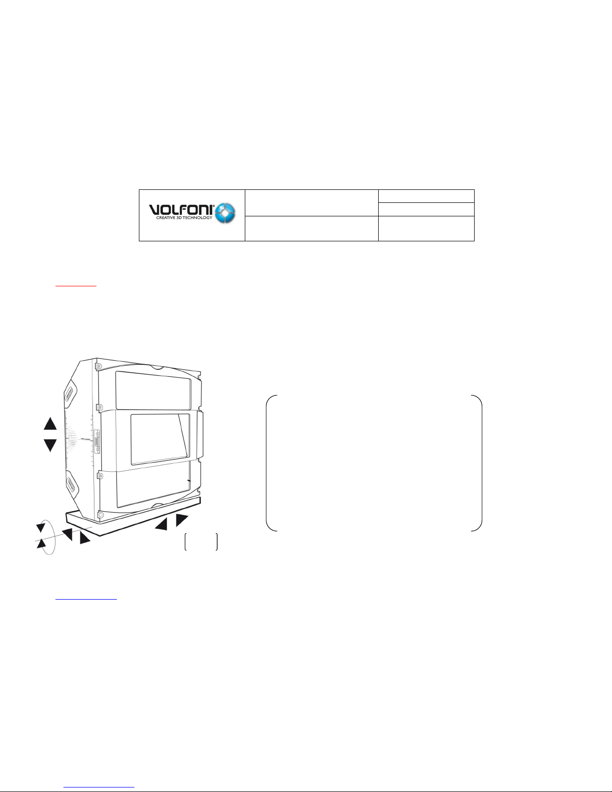
Adjust the position (height, angle) of the SmartCrystal™ Diamond Box in relation to the beam light from the projector using the
graduations on the sides of the SmartCrystal™ Diamond Box.
To fit this, use the carriage adjustment units of the bracket
The ideal position is when the beam light is centered at the inflow and at the outflow of the SCD Box, as mentioned by the figures
below.
- This step might alter slightly the position of the SCD Box in relation to the projector lens. Check again (removal/bringing close) by
making the carriage slide:
- There must be no contact between the device and the projector (lens included).
The SmartCrystal™ Diamond Box must be as close as possible to the projector lens without touching it, i.e. less than 2cm.
Fit in the bracket again if necessary.
If you alter one of the adjustments (position or orientation), you systematically need to carry out all the checks and repeat the
process as many times as necessary. If you have respected the procedure, one iteration should be enough.
As the position and the orientation are satisfying, the SCD Box is installed.
Fig 20

SmartCrystal™ Diamond
n ° : MUV140036
Version : A12
USER MANUAL
Date : 11/01/2018
www.volfoni.com This document is the property of the Co VOLFONI and may not be reproduced or disclosed without permission. 36
There are more information in looking at ANNEXE 06 Precision and tilt adjustments.
STEP 50
STEP 51
Lock bracket height with the right and left rings
Lock bracket angle with the counter screw

SmartCrystal™ Diamond
n ° : MUV140036
Version : A12
USER MANUAL
Date : 11/01/2018
www.volfoni.com This document is the property of the Co VOLFONI and may not be reproduced or disclosed without permission. 37
4. 2-D/3-D position stops positioning
The stops enable you to define accurately and permanently the positions of the SCD Box for the 2-D and 3-D projection modes
Adjustment of the 3-D position
In 3-D mode, the SCD Box must be positioned so that the projector beam outflow is horizontally centered on the central window of
the projector front and also on the outflow window (screen side).
Fixing the 3-D position:
If possible, look at the SmartCrystal™ Diamond Box screen side
and make sure that the central image is properly centered
At this moment, do not worry about the position of the upper
and lower half images
Look at the SmartCrystal™ Diamond Box inflow window and
make sure that the central image is properly centered like Fig 21
As the SmartCrystal™ Diamond Box is properly positioned, lock
the bracket stop in 3-D position (see step 55).
It is then possible to make the carriage slide and to come back
easily and accurately to this position
Adjustment of the 2-D position
In 2-D mode, the position of the SCD Box
should not interfere with the projector beam.
Make the bracket carriage slide until the
SCD Box is out of the beam light.
Do not hesitate to take a margin of room in
order to avoid any subsequent problem.
As the SmartCrystal™ Diamond Box is
properly positioned; lock the bracket stop in
2-D position.
Fig 21
Fig 22

SmartCrystal™ Diamond
n ° : MUV140036
Version : A12
USER MANUAL
Date : 11/01/2018
www.volfoni.com This document is the property of the Co VOLFONI and may not be reproduced or disclosed without permission. 38
STEP 52
STEP 53
Check inflow image is well centered (vertically and
horizontally). Image size has to be < 10cm x 7cm
Check 3 outflow images are well centered
STEP 54
STEP 55
Adjust, set and lock 2D bracket position sensor
Lock 3D bracket position sensor

SmartCrystal™ Diamond
n ° : MUV140036
Version : A12
USER MANUAL
Date : 11/01/2018
www.volfoni.com This document is the property of the Co VOLFONI and may not be reproduced or disclosed without permission. 39
STEP 56
STEP 57
Put wires properly
Connect all cables except synchronization and RJ45 cables. You
must plug the power supply of the SCD controller

SmartCrystal™ Diamond
n ° : MUV140036
Version : A12
USER MANUAL
Date : 11/01/2018
www.volfoni.com This document is the property of the Co VOLFONI and may not be reproduced or disclosed without permission. 40
5. Electrical installation and projector settings
The connection of the system is such as the following
figure:
Connect the SUBD9 cable with the SCD Box and
the SCD Controller.
Connect the synchronization cable (GPIO37 /
BNC or GPIO15 / BNC) with the projector and
the SCD Controller.
Connect the SUBD15 cable with the SCD Box
and the bracket.
Connect the bracket feeding cable.
The system is working:
o The SCD Controller displays the value of the synchronization frequency
given by the projector
o If the projector is in 3-D mode, the SCD Controller displays: ‘3D ON’
o If the projector is in 2-D mode, the SCD Controller displays: ‘2D’
The SCD Controller also displays the status of the SCD Box bracket:
Fig 24
Fig 23

SmartCrystal™ Diamond
n ° : MUV140036
Version : A12
USER MANUAL
Date : 11/01/2018
www.volfoni.com This document is the property of the Co VOLFONI and may not be reproduced or disclosed without permission. 41
STEP 58
STEP 59
Use the 1st contact to position the SCD in 2D position.
Look at the Controller box screen :
- If 2D-00Hz-Bracket OK : nothing more to do,
- If 2D-00Hz-Bracket unready : Use the 2nd contact to
display the right parameters => 2D-00Hz-Bracket OK
The SCD displays now the right parameters. We are in
2D position and we have 2D / 00.0Hz / BRACKET OK

SmartCrystal™ Diamond
n ° : MUV140036
Version : A12
USER MANUAL
Date : 11/01/2018
www.volfoni.com This document is the property of the Co VOLFONI and may not be reproduced or disclosed without permission. 42
STEP 60
Projector settings
- 3D ON
- Dark time = 350µs or 1000µs (see table below)
ELECTRONIC BOX
OPTICAL BOX
DARKTIME
VSSP ≥ 10200
VSSP ≥ 13300
350µS
VSSP 10100
VSSP ≤ 13200
1000µS
VSSP 10000
VSSP ≤ 13200
1000µS
If you notice an excessive ‘ghosting’ effect, test other values for the Darktime,
increasing it. Do not hesitate to contact your technical support.
- Delay = 0µs
- 3D Synchronization output activated
- Triple flash / 6:2 / 48Hz
SCD Controller display
- Connect synchronization cable to SCD Controller
- SCD will reach automatically 3D position
- SCD Controller will display : 3D ON / 72Hz / BRACKET OK

SmartCrystal™ Diamond
n ° : MUV140036
Version : A12
USER MANUAL
Date : 11/01/2018
www.volfoni.com This document is the property of the Co VOLFONI and may not be reproduced or disclosed without permission. 43
6. The SmartCrystal™ Diamond box Image adjustment
The installation and the positioning of the SmartCrystal™ Diamond Box are now completed. Re-position the SCD Box in front of the
projector lens (3-D position) for the next operation (image adjustment).
Image adjustment
Now that the SCD Box is properly positioned, we can carry out the image adjustment. The principle consists in aligning every half
image (upper and lower) with the central image
The fitting wheels are located on each side so as on the projector side of the SmartCrystal™ Diamond Box.
On one side of the SmartCrystal™ Diamond Box, you will find the up/down adjustment wheels of the upper half image (at the
top) so as of the lower half image (at the bottom). They can be spotted with the ‘left/right’ inscription.
On the other side of the SmartCrystal™ Diamond Box, you will find the right/left adjustment wheels of the upper half image (at
the top) and of the lower half image (at the bottom). They can be spotted with the ‘left/right’ inscription.
On the front projector side of the SmartCrystal™ Diamond Box, you will find the zoom in/out wheel for the upper half image (at
the top) and the zoom in/out wheel for the lower half image (at the bottom). They can be spotted with the ‘adjust’ inscription.
STEP 61
Loading the adjustment pattern
Please load the adjustment pattern into the server and
display it on the screen. The pattern is stored in the
USB key provided with the device.

SmartCrystal™ Diamond
n ° : MUV140036
Version : A12
USER MANUAL
Date : 11/01/2018
www.volfoni.com This document is the property of the Co VOLFONI and may not be reproduced or disclosed without permission. 44
Before starting the image adjustment, display the Volfoni adjustment pattern on the screen. The observed screen image shows line
splitting and different gaps between the upper and the lower parts of the image.
Fitting the upper half image
The purpose of this step is to superimpose all the information of the upper half of the image proceeding as following:
First of all you need to make sure that the adjustable wheel is unlocked.
To do so, you have to maintain in position the top part of the adjustable wheel (1) then unscrew (rotate counterclockwise) the
bottom part of the adjustable wheel (2) until feeling the stop. During this step you must not force. This locking system is working on the
principle nut/locknut. The system is now ready to be set.
Left/right fitting observing the VERTICAL lines
Fig 25

SmartCrystal™ Diamond
n ° : MUV140036
Version : A12
USER MANUAL
Date : 11/01/2018
www.volfoni.com This document is the property of the Co VOLFONI and may not be reproduced or disclosed without permission. 45
Align/superimpose the vertical lines at the center of the upper image using the left/right wheel located at the top of the device
(n°1 wheel of the figure 5).
When the aligning is correct at the center, the vertical lines on the image sides are not systematically superimposed. Check that
gaps between the lines are identical on the left and the right of the image (see image below).
Up/down fitting observing the HORIZONTAL lines
Fig 26

SmartCrystal™ Diamond
n ° : MUV140036
Version : A12
USER MANUAL
Date : 11/01/2018
www.volfoni.com This document is the property of the Co VOLFONI and may not be reproduced or disclosed without permission. 46
o Align/superimpose the horizontal line(s) of the upper image using the ‘up/down’ wheel located at the top of the device (n°3 wheel
of the figure 5). Focus mainly on the center of the image (the horizontal lines at the top of the image are probably still irregular, which
is not disturbing at the moment).
‘Scale/zoom’ size fitting
Using the upper central wheel (n°6 wheel of the figure 5), fit the size of the upper half image superimposing all the information (lines,
circles, text).
Lock the upper half image
Fig 27
Fig 28

SmartCrystal™ Diamond
n ° : MUV140036
Version : A12
USER MANUAL
Date : 11/01/2018
www.volfoni.com This document is the property of the Co VOLFONI and may not be reproduced or disclosed without permission. 47
At the end of the previous adjustment, the superimposition might not be optimum.
The three previous steps need to be repeated, proceeding to a finer fitting until you get a satisfying result. The adjustment is satisfying
when there is no image splitting on the upper half image anymore.
Now as the adjustment of the top image is completed you have to lock it.
To do so, you have to maintain in position the top part of the adjustable wheel (1) then screw (rotate clockwise) the bottom part of
the adjustable wheel (2) until the stop.
The locking can have a slight impact on the ‘Scale/zoom’ size fitting.
In this case you have to unlock the adjustable wheel (do the contrary of the previous step) then start over until finding the good
balance.
Fig 29

SmartCrystal™ Diamond
n ° : MUV140036
Version : A12
USER MANUAL
Date : 11/01/2018
www.volfoni.com This document is the property of the Co VOLFONI and may not be reproduced or disclosed without permission. 48
Lock the left/right button
If the vertical alignment moved, remove the locking mechanical piece, redo the vertical alignment and fix again the locking
mechanical piece until having a perfect vertical alignment after tightening the knurl screw.
In general the horizontal moved after this step it is normal.
STEP 62
Unscrew the right top silver screw located on the aluminum cover
STEP 63
Fix the locking mechanical piece by tightening the screw as illustrated

SmartCrystal™ Diamond
n ° : MUV140036
Version : A12
USER MANUAL
Date : 11/01/2018
www.volfoni.com This document is the property of the Co VOLFONI and may not be reproduced or disclosed without permission. 49
Lock the up/down button.
If the horizontal and/or vertical alignment moved, remove the locking mechanical piece, redo the alignment and fix again the
locking mechanical piece until having a perfect alignment after tightening the knurl screw. It might be necessary to redo this last
step 2 or 3 times.
The adjustment and locking of the upper half image is completed.
STEP 64
Unscrew the right top silver screw located on the aluminum cover
STEP 65
Fix the locking mechanical piece by tightening the screw as illustrated

SmartCrystal™ Diamond
n ° : MUV140036
Version : A12
USER MANUAL
Date : 11/01/2018
www.volfoni.com This document is the property of the Co VOLFONI and may not be reproduced or disclosed without permission. 50
Fitting the lower half image
Follow the same procedure for bottom image
The purpose of this step is to superimpose all the information of the lower half of the image proceeding as following:
First of all you need to make sure that the adjustable wheel is unlocked. To do so, you have to maintain in position the top part of the
adjustable wheel (1) then unscrew (rotate counterclockwise) the bottom part of the adjustable wheel (2) until feeling the stop.
During this step you must not force. This locking system is working on the principle nut/locknut. The system is now ready to be set.
Fig 30

SmartCrystal™ Diamond
n ° : MUV140036
Version : A12
USER MANUAL
Date : 11/01/2018
www.volfoni.com This document is the property of the Co VOLFONI and may not be reproduced or disclosed without permission. 51
Left/right fitting observing the VERTICAL lines
Align/superimpose the vertical lines at the center of the lower image using the left/right wheel located at the bottom of the
device (n°2 wheel of the image 5).
As the aligning is correct at the center, the vertical lines on the image sides are not systematically superimposed. Check
however that the gaps between the lines are identical on the left and the right of the image (see figure below).
¶Up/down fitting observing the HORIZONTAL lines
Fig 31

SmartCrystal™ Diamond
n ° : MUV140036
Version : A12
USER MANUAL
Date : 11/01/2018
www.volfoni.com This document is the property of the Co VOLFONI and may not be reproduced or disclosed without permission. 52
Align/superimpose the horizontal line(s) of the lower image using the ‘up/down’ wheel located at the bottom of the device (n°4 wheel of the
figure 5). Focus mainly on the center of the image (the horizontal lines at the top of the image are likely still irregular, which is not disturbing at the
moment).
•
‘Scale/zoom’ size fitting
Using the central wheel (n°7 wheel of the figure 5), fit the size of the lower half image by superimposing all the information (lines, circles, text).
•
¶Final fitting
Fig 32
Fig 33

SmartCrystal™ Diamond
n ° : MUV140036
Version : A12
USER MANUAL
Date : 11/01/2018
www.volfoni.com This document is the property of the Co VOLFONI and may not be reproduced or disclosed without permission. 53
At the end of the previous adjustment, the superimposition might not be optimum.
The three previous steps need to be repeated, proceeding to a finer fitting until you get a satisfying
result. The adjustment is satisfying when there is no splitting information on the lower half image.
•
Final locking
Now as the adjustment of the bottom image is completed
you have to lock it.
To do so, you have to maintain in position the top part of
the adjustable wheel (1)
then screw (rotate clockwise) the bottom part of the
adjustable wheel (2) until the stop.
The locking can have a slight impact on the ‘Scale/zoom’
size fitting.
In this case you have to unlock the adjustable wheel (do
the opposite of the previous step) then start over until
finding the good balance.
THE LOWER HALF IMAGE ADJUSTMENT IS
COMPLETED.
Fig 34

SmartCrystal™ Diamond
n ° : MUV140036
Version : A12
USER MANUAL
Date : 11/01/2018
www.volfoni.com This document is the property of the Co VOLFONI and may not be reproduced or disclosed without permission. 54
Lock the left/right button
If the vertical alignment moved, remove the locking mechanical piece, redo the vertical alignment and fix again the locking
mechanical piece until having a perfect vertical alignment after tightening the knurl screw.
In general, the horizontal alignment moved after this step.
STEP 66
Unscrew the right top silver screw located on the aluminium cover
STEP 67
Fix the locking mechanical piece by tightening the screw as illustrated

SmartCrystal™ Diamond
n ° : MUV140036
Version : A12
USER MANUAL
Date : 11/01/2018
www.volfoni.com This document is the property of the Co VOLFONI and may not be reproduced or disclosed without permission. 55
Lock the up/down button
If the horizontal and/or vertical alignment moved, remove the locking mechanical piece, redo the alignment and fix again the
locking mechanical piece until having a perfect alignment after tightening the knurl screw. It might be necessary to redo this last
step 2 or 3 times. The bottom image is now locked.
THE IMAGE ADJUSTMENT AND LOCKING IS COMPLETED.
STEP 68
Unscrew the right top silver screw located on the aluminium cover
STEP 69
Fix the locking mechanical piece by tightening the screw as illustrated

SmartCrystal™ Diamond
n ° : MUV140036
Version : A12
USER MANUAL
Date : 11/01/2018
www.volfoni.com This document is the property of the Co VOLFONI and may not be reproduced or disclosed without permission. 56
The result expected
STEP 70
With the Volfoni test
pattern you will a perfect
match between the
three superposed
images.
Volfoni test pattern after alignment (line=3 pixels)

SmartCrystal™ Diamond
n ° : MUV140036
Version : A12
USER MANUAL
Date : 11/01/2018
www.volfoni.com This document is the property of the Co VOLFONI and may not be reproduced or disclosed without permission. 57
If you use the Cross Hatch test pattern (line = 1 pixels) you may observe some local disparities. The figure below shows the maximum
disparity in overlay of the two images. We recommend using the Volfoni test pattern.
www.volfoni.com This document is the property of the Co VOLFONI and may not be reproduced or disclosed without permission. 57

SmartCrystal™ Diamond
n ° : MUV140036
Version : A12
USER MANUAL
Date : 11/01/2018
www.volfoni.com This document is the property of the Co VOLFONI and may not be reproduced or disclosed without permission. 58
III.
ADDITIONAL ANTI-REFLECTION FILTER
1. Context
An optional additional filter is in the packaging.
In some installations, some ‘room’ windows may not be processed with
an anti-glare layer or it might be insufficient/inadequate.
In this case, you might notice undesirable reflections on the screen.
Volfoni has developed this filter in order to compensate for this situation to the detriment of a loss of light power. We recommend using
this filter as a last resort only and advise instead to change the window angle in order to deflect the reflection or to change it.
2. Filter assembly
It is absolutely essential to carry out this process after the
SmartCrystal™ Diamond Box has been dismantled from the
bracket, and to make all necessary arrangements to protect the
equipment before operating. Any operation on this installed unit is
delicate and may probably damage it.
Proceed as following to assemble the filter:
Before any operation, it is necessary to have a clean and secured work
environment for the SmartCrystal™ Diamond Box so as its filter.
Dismantle the SmartCrystal™ Diamond Box from its bracket.
Dismantle the mask located under the central window of the SmartCrystal™
Diamond Box (screen side), in purple in figure 21. The two screws located on
each side must be unscrewed.
As you have dismantled this component, we invite you to keep it carefully.
Insert the filter making it slide like the following figure.
Fig 35
Fig 36

SmartCrystal™ Diamond
n ° : MUV140036
Version : A12
USER MANUAL
Date : 11/01/2018
www.volfoni.com This document is the property of the Co VOLFONI and may not be reproduced or disclosed without permission. 59
Warning: never force and never leave the device without mask or filter.
Fix the filter with the two screws initially used to fix the mask.
The operation is now completed. Reposition the device and check that the reflections
have disappeared.
This operation may have disturbed the installation and the system adjustments.
IV.
SOFTWARE INTERFACE
1. Introduction
The system is run by the SCD Controller.
Several operations can be carried out such as:
Update of the software version of the SCD system
Change of the default working settings (3-D mode automatic detection for instance)
Diagnosis (unavailable)
2. SCD software version
The system is run by the SCD Controller. By default, the system is delivered with the newest software version at the moment the
product was manufactured. A new software version might be available when you receive/install your system.
On receipt of equipment, Volfoni recommends to carry out the following operations to ensure you have the latest software version:
Visit the Volfoni website: www.volfoni.com
Select the ‘SERVICES/SUPPORT’ menu
Select ‘DOWNLOAD’
Download, install and launch the ‘VOLFONI LOADER’ program
Connect your computer with the SmartCrystal™ Diamond Controller using the USB-A /USB-B cable (cable provided by Volfoni)
Feed the SmartCrystal™ Diamond Controller with the external feeding (provided by Volfoni)
Fig 37

SmartCrystal™ Diamond
n ° : MUV140036
Version : A12
USER MANUAL
Date : 11/01/2018
www.volfoni.com This document is the property of the Co VOLFONI and may not be reproduced or disclosed without permission. 60
Check that the program recognizes the SmartCrystal™ Diamond Controller
As the SmartCrystal™ Diamond Controller is connected, press ‘CHECK FOR UPDATE. If your system uses the latest version, the
program will indicate that your system is up to date. If the version is not the latest, accept and launch the new version loading.
During this process, warning:
Do not disconnect the SCD Controller from your computer
Do not unplug the SCD Controller feeding
3. Functioning modes, settings, other functions
The SCD Controller has other functions:
Activation/inhibition of the working mode
Settings change
Remote running (Network Operating Center)
Functioning data recording
For further information, refer to the XXXX document (Document in progress, please contact Volfoni support), which contains all the
information. For any question, do not hesitate to contact your support.

SmartCrystal™ Diamond
n ° : MUV140036
Version : A12
USER MANUAL
Date : 11/01/2018
www.volfoni.com This document is the property of the Co VOLFONI and may not be reproduced or disclosed without permission. 61
V.
TROUBLES SHOOTING
PROBLEM
Hazy image,
poor contrast
POSSIBLE REASONS
• The lens focus is wrong
• The image aligning is bad
• The protective films on the front and back sides have
not been removed
• Presence of fingerprints or dirt on the lens and/or on
the SCD Box inflow and outflow windows
SOLUTIONS
• Fit the lens focus
• Check if the protective films have been removed
• Remove the protective films and clean the inflow and outflow SCD
Box windows using the provided wipes
• Adjust the SCD Box aligning again using the pattern
No 3-D effect
• Problem on the silvered screen
• Projector settings are not right
• The SCD Box is not connected with the SCD Controller
• The SCD Controller is not plugged in
• The projection window depolarizes light
• The SCD B
• Box and the SCD Controller are not compatible
• Check if the screen is silvered
• Check if the ‘DarkTime’ and ‘Delay’ values are right
• Check the SCD Controller connections. In 3-D mode, the SCD
Controller should display ‘3D ON’ and the frequency.
• Carry out a checking by removing the room window to ensure the
latter do not influence polarization
• Check the table compatibility table below
ELECTRONIC BOX
OPTICAL BOX
DARKTIME
VSSP ≥ 10200
VSSP ≥ 13300
350µS
VSSP 10100
VSSP ≤ 13200
1000µS
VSSP 10000
VSSP ≤ 13200
1000µS
Too dark image
• The power of the projector lamp is too low
• The lamp settings are badly adjusted
• Change the lamp settings

SmartCrystal™ Diamond
n ° : MUV140036
Version : A12
USER MANUAL
Date : 11/01/2018
www.volfoni.com This document is the property of the Co VOLFONI and may not be reproduced or disclosed without permission. 62
The image seems to be
in 3D but the rendering
is uncomfortable
• The right/left live wire is reversed on the projector
•Change the right/left live wire (switch from ‘TRUE’ to ‘INVERTED’ or
conversely) on the projector
Flickering image
• The SmartCrystal™ Diamond settings are faulty
• The content is not 3-D
• The image frequency given by the projector is not
right
• Check the SmartCrystal™ Diamond settings
• Check if the content is in 3D
• Try to check the image frequency given by the projector (see SCD
Controller display)
Bracket Error
• High voltage
• Let everything plug and press the reset button of the bracket
IF YOU DO NOT NOTICE ANY IMPROVEMENT FURTHER TO THE SUGGESTED SOLUTIONS, PLEASE CONTACT YOUR SUPPORT

SmartCrystal™ Diamond
n ° : MUV140036
Version : A12
USER MANUAL
Date : 11/01/2018
www.volfoni.com This document is the property of the Co VOLFONI and may not be reproduced or disclosed without permission. 63
VI.
IMPORTANT SAFETY RECOMMENDATIONS
Protect all parts of the 3D system from direct sunlight, heat or water.
Extreme conditions may alter the product’s performance.
Do not modify the electrical or mechanical components of your 3D system.
Do not apply force to the window of the polarization modulator.
Do not touch the polarization window.
Avoid vibrations and shock.
Use a clean soft cloth when cleaning the polarization modulator to avoid scratching.
Always transport the SmartCrystal™ Diamond system in its original packaging to avoid scratching the LCDs or the frame.
In case of damage to the SmartCrystal™ Diamond where the skin is exposed to liquid crystal material, we recommend that you
immediately wash the area with soap and water.
In case of eye exposure to liquid crystal material, please seek medical advice immediately.
Please note that passive 3D glasses must not be used as sunglasses.
VII.
WARRANTY
The SmartCrystal™ Diamond is protected under warranty to the original purchaser for three (3) years according to local legislation.
Equipment (modules and cables) should be returned in their original packaging along with the original proof of purchase. Equipment that
is broken or scratched is not covered. Volfoni does not guarantee uninterrupted or error-free operation of the product.
VIII.
FURTHER INFORMATION
NOTICE:
The Volfoni Group reserves the right to make changes in the hardware, packaging or other documentation without prior written
notice. SmartCrystal™ Diamond is a trademark of the Volfoni Group. All trademarks are the property of their respective companies.
www.volfoni.com

SmartCrystal™ Diamond
n ° : MUV140036
Version : A12
USER MANUAL
Date : 11/01/2018
www.volfoni.com This document is the property of the Co VOLFONI and may not be reproduced or disclosed without permission. 64
IX.
REGULATORY STANDARDS
European Union - Disposal information
This symbol means that according to local laws and regulations your product should be disposed of separately from household
waste. When this product reaches the end of its life, take it to a collection point designated by local authorities. Some collection
points accept product for free.
The separate collection and recycling of your product at the time of disposal will help conserve natural resources and ensure that it is
recycled in a manner that protects human health and the environment.
This Class B digital apparatus complies with Canadian ICES-003.

SmartCrystal™ Diamond
n ° : MUV140036
Version : A12
USER MANUAL
Date : 11/01/2018
www.volfoni.com This document is the property of the Co VOLFONI and may not be reproduced or disclosed without permission. 65
ANNEXE 01
VASP-09xxx SCD bracket installation
The technical Specifications
DIMENSIONS: 900 x 310 x
150mm
NET WEIGHT: 13 kg
PACKING DIMENSIONS : 1000
x 370 x 250mm
GROSS WEIGHT : 14 kg.
FINISH IN : Aluminum powder
coating
COLOR: Aluminum Grey and
black
TILT RANGE: 15°
MAX. HIGH ADJUSTMENT
TABLE OPTION: 145 mm + 30
mm
BENCH OPTION: 208 mm + 30
mm
HIGH PRECISION ADJUSTMENT
+/- 30 mm
HORIZONTAL ADJUSTMENT
COURSE: 250 mm + 200 mm

SmartCrystal™ Diamond
n ° : MUV140036
Version : A12
USER MANUAL
Date : 11/01/2018
www.volfoni.com This document is the property of the Co VOLFONI and may not be reproduced or disclosed without permission. 66
List of accessories
The kit includes all necessary accessories for mounting the support in all possible ways. It also includes the necessary screws.
The bracket is included in the KIT to assembly on site. Main parts are already assembled.
The packing includes a set of Allen wrenches to mount the bracket (2mm – 2.5mm – 3mm – 4mm – 5mm)

SmartCrystal™ Diamond
n ° : MUV140036
Version : A12
USER MANUAL
Date : 11/01/2018
www.volfoni.com This document is the property of the Co VOLFONI and may not be reproduced or disclosed without permission. 67
Installation and adjustment on the support overview
Several steps to install the
SCD on the Bracket
- Fixing the SCD on the
support with 4 screws.
- Adjustment of the
Horizontal position. SCD
must be as closed as
possible to the lens of
the lens of the projector
- Adjustment of the
vertical position: Beam
light should enter in the
center of the entrance
windows of the SCD.
- Adjustment of the SCD
angle

SmartCrystal™ Diamond
n ° : MUV140036
Version : A12
USER MANUAL
Date : 11/01/2018
www.volfoni.com This document is the property of the Co VOLFONI and may not be reproduced or disclosed without permission. 68
Setting 2D and 3D position
The bracket has two sensors to
define 2D and 3D position. The
position of theses sensors must
be adjusted depending on
the position of the lens and will
define the limits of the SCD
displacement.

SmartCrystal™ Diamond
n ° : MUV140036
Version : A12
USER MANUAL
Date : 11/01/2018
www.volfoni.com This document is the property of the Co VOLFONI and may not be reproduced or disclosed without permission. 69
The bracket installation
STEP 01
STEP 02
Choose your configuration => ANNEXE 01 to 05
Bracket Maximum distance.
Minimum height
Depending on your configuration
Fix F & G parts

SmartCrystal™ Diamond
n ° : MUV140036
Version : A12
USER MANUAL
Date : 11/01/2018
www.volfoni.com This document is the property of the Co VOLFONI and may not be reproduced or disclosed without permission. 70
STEP 03
STEP 04
Fix D & E parts
Fix O part
STEP 05 (Part 1/2)
STEP 05 (Part 2/2)
Fix L parts
Fix A part on O & L parts

SmartCrystal™ Diamond
n ° : MUV140036
Version : A12
USER MANUAL
Date : 11/01/2018
www.volfoni.com This document is the property of the Co VOLFONI and may not be reproduced or disclosed without permission. 71
STEP 06
STEP 07
If the length of the projector’s lens is more
than 15 centimeters
Please follow the procedure if not please go
directly to the STEP 10
Do not forget to screw 2 L parts
Bracket feet installation : Parts & tools
STEP 08
STEP 09
Positioning I part
After positioning J part, fix screw I part. The same operation has
to be done on the other side of the bracket

SmartCrystal™ Diamond
n ° : MUV140036
Version : A12
USER MANUAL
Date : 11/01/2018
www.volfoni.com This document is the property of the Co VOLFONI and may not be reproduced or disclosed without permission. 72
STEP 10
STEP 11
Bracket feet installation : Parts & tools
Fix screws & bolts on P & Q parts
STEP 12
STEP 13
Fix P &Q on both sides of the bracket
Fix R part

SmartCrystal™ Diamond
n ° : MUV140036
Version : A12
USER MANUAL
Date : 11/01/2018
www.volfoni.com This document is the property of the Co VOLFONI and may not be reproduced or disclosed without permission. 73
STEP 14
STEP 15
Put the bolt in the middle hole of R
Fix T part and adjust its position

SmartCrystal™ Diamond
n ° : MUV140036
Version : A12
USER MANUAL
Date : 11/01/2018
www.volfoni.com This document is the property of the Co VOLFONI and may not be reproduced or disclosed without permission. 74
STEP 16
STEP 17
Remove protection guide
Remove 2 bracket position sensors wires from guide
STEP 18
STEP 19
Unscrew 2 bracket position sensors
In this configuration, move right position sensor from its position till a
position that will allow to put bracket upper plate face to projector

SmartCrystal™ Diamond
n ° : MUV140036
Version : A12
USER MANUAL
Date : 11/01/2018
www.volfoni.com This document is the property of the Co VOLFONI and may not be reproduced or disclosed without permission. 75
STEP 20
General view of the bracket
electronic
1st button : not used
2nd button : reset button
Left contact : Motor command
Right contact : Set 2D / 3D position
Left led : 12V
Right led : 5V

SmartCrystal™ Diamond
n ° : MUV140036
Version : A12
USER MANUAL
Date : 11/01/2018
www.volfoni.com This document is the property of the Co VOLFONI and may not be reproduced or disclosed without permission. 76
STEP 21
STEP 22
Power on bracket
Check 2 leds red
Bracket upper plate is at 2D position
STEP 23
STEP 24
Use left contact
Bracket will move and will stop face to bracket position
sensor. The bracket upper plate will be approximately
face to projector

SmartCrystal™ Diamond
n ° : MUV140036
Version : A12
USER MANUAL
Date : 11/01/2018
www.volfoni.com This document is the property of the Co VOLFONI and may not be reproduced or disclosed without permission. 77
STEP 25
STEP 26
Unscrew 2 screws of the rings on both side of the trolley
Loosen stud bolt of the trolley
STEP 27
STEP 28
Set bracket upper plate at middle position
Set bracket tilt at 0°
Check distance between bracket upper plate and
middle of projector lens. Right distance should be
approximately 13cm

SmartCrystal™ Diamond
n ° : MUV140036
Version : A12
USER MANUAL
Date : 11/01/2018
www.volfoni.com This document is the property of the Co VOLFONI and may not be reproduced or disclosed without permission. 78
STEP 29
STEP 30
In case of bracket upper plate too high or too low
Readjust its position by modifying D & E parts position
Check horizontality is good
STEP 31
STEP 32
In the next step we will mount the Scd on
the bracket.
Please go to Step 41 page 31
Unscrew the 4 screws on the both side of the endless
screw

SmartCrystal™ Diamond
n ° : MUV140036
Version : A12
USER MANUAL
Date : 11/01/2018
www.volfoni.com This document is the property of the Co VOLFONI and may not be reproduced or disclosed without permission. 79
ANNEXE 02
Mounting the bracket in the projector legs

SmartCrystal™ Diamond
n ° : MUV140036
Version : A12
USER MANUAL
Date : 11/01/2018
www.volfoni.com This document is the property of the Co VOLFONI and may not be reproduced or disclosed without permission. 80
STEP 01
STEP 02
STEP 03
Assemble parts A, L and M.
Screw parts A and L.
Repeat operation
STEP 04
STEP 05
STEP 06
The 2 L parts are screwed onto part
A. on the other side.
Take parts F and M.
Screw part D to part A.

SmartCrystal™ Diamond
n ° : MUV140036
Version : A12
USER MANUAL
Date : 11/01/2018
www.volfoni.com This document is the property of the Co VOLFONI and may not be reproduced or disclosed without permission. 81
STEP 07
STEP 08
STEP 09
Screw parts D and L.
Unscrew projector foot. Repeat
process with part E
Insert parts F and G in each
projector foot
STEP 10
STEP 11
STEP 12
Put back projector feet with F and
G parts attached.
Screw bracket to F and G parts.
Loosen bracket screws Adjust
height. (DO NOT TAKE OUT)

SmartCrystal™ Diamond
n ° : MUV140036
Version : A12
USER MANUAL
Date : 11/01/2018
www.volfoni.com This document is the property of the Co VOLFONI and may not be reproduced or disclosed without permission. 82
STEP 13
STEP 14
STEP 15
Adjust according to the lens
installed.
Adjust manually with the Tighten
screws from step 12
Adjust stop sensor to the control
board
STEP 16
Fix the sensor to its limit switch desired position

SmartCrystal™ Diamond
n ° : MUV140036
Version : A12
USER MANUAL
Date : 11/01/2018
www.volfoni.com This document is the property of the Co VOLFONI and may not be reproduced or disclosed without permission. 83
ANNEXE 03
Mounting the bracket in the projector bench

SmartCrystal™ Diamond
n ° : MUV140036
Version : A12
USER MANUAL
Date : 11/01/2018
www.volfoni.com This document is the property of the Co VOLFONI and may not be reproduced or disclosed without permission. 84
STEP 01
STEP 02
STEP 03
Use adequate screws
Screw parts F and G. Pedestal
(OPTION 1) Maximum bracket
height
STEP 04
STEP 05
STEP 06
(OPTION 2) Minimum bracket
height
Place the bracket after repeated
Steps 01 to 07 ANNEXE 01
Pin up bracket with part M to parts
F and G

SmartCrystal™ Diamond
n ° : MUV140036
Version : A12
USER MANUAL
Date : 11/01/2018
www.volfoni.com This document is the property of the Co VOLFONI and may not be reproduced or disclosed without permission. 85
STEP 07
STEP 08
STEP 09
Once fitted in place
Insert K parts (covers)
If needed, lenght can be
increased
STEP 10
STEP 11
STEP 12
Bracket with attachment
Insert K parts (covers)
Bracket with attachment

SmartCrystal™ Diamond
n ° : MUV140036
Version : A12
USER MANUAL
Date : 11/01/2018
www.volfoni.com This document is the property of the Co VOLFONI and may not be reproduced or disclosed without permission. 86
STEP 13
STEP 14
(OPTION 1) Bracket at maximum height
(OPTION 2) Bracket at minimum height

SmartCrystal™ Diamond
n ° : MUV140036
Version : A12
USER MANUAL
Date : 11/01/2018
www.volfoni.com This document is the property of the Co VOLFONI and may not be reproduced or disclosed without permission. 87
ANNEXE 04
Mounting the desktop bracket

SmartCrystal™ Diamond
n ° : MUV140036
Version : A12
USER MANUAL
Date : 11/01/2018
www.volfoni.com This document is the property of the Co VOLFONI and may not be reproduced or disclosed without permission. 88
STEP 01
STEP 02
STEP 03
Take parts A, H, M and N
Screw parts A and H
Adjust height
STEP 04
STEP 05
STEP 06
Place bracket on the table
Screw the four fixing points
Bracket screwed to the table

SmartCrystal™ Diamond
n ° : MUV140036
Version : A12
USER MANUAL
Date : 11/01/2018
www.volfoni.com This document is the property of the Co VOLFONI and may not be reproduced or disclosed without permission. 89
ANNEXE 05
Wall mounting solution

SmartCrystal™ Diamond
n ° : MUV140036
Version : A12
USER MANUAL
Date : 11/01/2018
www.volfoni.com This document is the property of the Co VOLFONI and may not be reproduced or disclosed without permission. 90
ANNEXE 06
Precision and tilt adjustments
Height precision adjustment
STEP 01
STEP 02
STEP 03
Loosen marked screws
Loosen the stud bolt
Adjust height
STEP 04
When SCC DIAMOND is at its desired position, fasten again bolts and screws

SmartCrystal™ Diamond
n ° : MUV140036
Version : A12
USER MANUAL
Date : 11/01/2018
www.volfoni.com This document is the property of the Co VOLFONI and may not be reproduced or disclosed without permission. 91
Tilt adjustment
STEP 01
STEP 02
Losen lower bushing
Adjust to desired position
STEP 03
Tighten lower bushing

SmartCrystal™ Diamond
n ° : MUV140036
Version : A12
USER MANUAL
Date : 11/01/2018
www.volfoni.com This document is the property of the Co VOLFONI and may not be reproduced or disclosed without permission. 92
ANNEXE 07
SCD bracket disengagement.
For the models VASP-09XXX please see annexe 08
WARNING: Please remove SCD product and disconnect the power supply cable before to disengage the bracket.
STEP 01
STEP 02
STEP 03
If you have a motor problem and you need
to move the SCD platform manually
First, lift the tray turning the button
We have to remove this piece
STEP 04
STEP 05
STEP 06
Remove the screw with Allen key
Once unscrewed, remove the piece
Now, we can move the platform manually

SmartCrystal™ Diamond
n ° : MUV140036
Version : A12
USER MANUAL
Date : 11/01/2018
www.volfoni.com This document is the property of the Co VOLFONI and may not be reproduced or disclosed without permission. 93
STEP 07
STEP 08
STEP 09
To put the bracket in the initial
configuration, position the gold piece
under the platform
The 4 holes must be perfectly aligned
Screw the piece to fix the platform.
The system is again motorized

SmartCrystal™ Diamond
n ° : MUV140036
Version : A12
USER MANUAL
Date : 11/01/2018
www.volfoni.com This document is the property of the Co VOLFONI and may not be reproduced or disclosed without permission. 94
ANNEXE 08
SCD bracket disengagement for the models VASP-09XXX.
The aim is to release the endless screw
WARNING: Please remove SCD product and disconnect the power supply cable before to disengage the bracket.
STEP 01
STEP 02
STEP 03
Start with motor mounted
Remove the control box cover; 4
screws
Remove the screws that are fixing the
control box to the motor box. 2 screws
STEP 04
STEP 05
STEP 06
Remove the motor cover: 2 screws
Remove the motor cover: 2 screws

SmartCrystal™ Diamond
n ° : MUV140036
Version : A12
USER MANUAL
Date : 11/01/2018
www.volfoni.com This document is the property of the Co VOLFONI and may not be reproduced or disclosed without permission. 95
STEP 07
STEP 08
Disconnect the J2, J3 cable and motor cable
Loosen the rod that secures the
motor shaft
STEP 09
STEP 10
STEP 11
Unscrew the motor support
Pull the motor and its support axially
stretching carefully in order not to break
the spindle housing to the engine
The endless screw is release
To assemble the motor, follow the same steps to remove it but in inverse order.
WARNING: Please place the cables before mounting the motor support
END
 Loading...