

Page 1
TM
STARPLUS
STS
Key Systems
System Programming & Operations Manual
December 2002 - Issue 1.0
Page 2

Issue Release Date Changes
1.0 12-02 Initial Release
LIFE SUPPORT APPLICATIONS POLICY
VODAVI Technology, Inc. products are not authorized for and should not be used
within Life Support applications. Life Support systems are equipment intended to
support or sustain life and whose failure to perform when properly used in
accordance with instructions provided can be reasonably expected to result in
significant personal injury or death.
VODAVI Technology, Inc. warranty is limited to replacement of defective
components and does not cover injury to persons or property or other consequential
damages.
Copyright © 2002 VODAVI Technology, Inc.
All Rights Reserved
This material is copyrighted by VODAVI Technology, Inc., and may be duplicated by Authorized
Dealers only. Any unauthorized reproductions, use or disclosure of this material, or any part
thereof, is strictly prohibited and is a violation of the Copyright Laws of the United States
(17 U.S.C. Section 101 et. seq.).
VODAVI reserves the right to make changes in specifications at any time and without notice. The
information furnished by VODAVI in this material is believed to be accurate and reliable, but is
not warranted to be true in all cases.
STARPLUS™ is a registered trademark of VODAVI Technology, Inc.
mlj/2002
Page 3

Contents
1Introduction
General Description ................................................................................................................................ 1-2
System Features ................................................................................................................................ 1-3
Digital Keyset Telephones ............................................................................................................. 1-4
Digital Keyset/Button Diagram .................................................................................................... 1-5
2 Features and Operation
About This Manual .................................................................................................................................. 2-2
Content Summary ............................................................................................................................ 2-2
Manual Format & Description ...................................................................................................... 2-3
911 Feature ................................................................................................................................................ 2-4
911 Alert ............................................................................................................................................... 2-5
Enhanced 911 Integration ............................................................................................................. 2-6
Enhanced 911 Power Failure Station ......................................................................................... 2-7
Account Codes .......................................................................................................................................... 2-7
Account Codes - Forced ................................................................................................................. 2-8
Account Codes - Traveling COS (Verified) ................................................................................ 2-9
Initialize Verified Account Code Table ...................................................................................... 2-12
Print Verified Account Codes ....................................................................................................... 2-13
Answering Machine Emulation ........................................................................................................... 2-14
Attendant Assignment/Features ........................................................................................................ 2-15
Automatic Privacy .................................................................................................................................... 2-16
Background Music ................................................................................................................................... 2-16
Battery Backup (Memory) ..................................................................................................................... 2-17
Baud Rate Assignments ......................................................................................................................... 2-17
Call Back ...................................................................................................................................................... 2-18
Manual Callback ................................................................................................................................ 2-18
Call Back Button Flash Rate ........................................................................................................... 2-19
Automatic Call Back Timer ............................................................................................................ 2-19
Auto Callback - DSS/BLF ................................................................................................................. 2-20
Message Callback - DSS/BLF Flash Rate .................................................................................... 2-20
Call Coverage ............................................................................................................................................. 2-21
Call Coverage Ring Timer ............................................................................................................... 2-22
Call Forward ............................................................................................................................................... 2-23
Call Forwarding ................................................................................................................................. 2-23
Call Forward - All Calls ..................................................................................................................... 2-25
Call Forward - Busy ........................................................................................................................... 2-26
Call Forward - Busy / No Answer ................................................................................................. 2-26
Call Forward - Follow Me ............................................................................................................... 2-27
Call Forward - No Answer .............................................................................................................. 2-29
Call Forward - External (Off-Net) ................................................................................................. 2-30
Contents - i
Page 4

Contents - ii
Call Forward Button Flash Rate .................................................................................................... 2-31
Call Forward Display ........................................................................................................................ 2-31
Call Forward - Preset ............................................................................................................................... 2-32
Preset Call Forward - Station ........................................................................................................ 2-33
Preset Call Forward - CO Line ....................................................................................................... 2-35
Preset Forward Voice Mail ID ........................................................................................................ 2-36
Preset Forward Timer (Incoming Call to a Destination) ...................................................... 2-37
Calling Forward Override ...................................................................................................................... 2-38
Calling Station Handsfree Mode Override ...................................................................................... 2-38
Calling Station Tone Mode Override ................................................................................................. 2-38
Call Park ....................................................................................................................................................... 2-39
Call Park - System .............................................................................................................................. 2-39
Call Park Recall Timer ...................................................................................................................... 2-40
Call Park - Personal ........................................................................................................................... 2-40
Call Park - Station .............................................................................................................................. 2-42
Call Pickup .................................................................................................................................................. 2-43
Directed Call Pickup ......................................................................................................................... 2-44
Group Call Pickup ............................................................................................................................. 2-45
Call Transfer ............................................................................................................................................... 2-46
Ringback on Transfer ....................................................................................................................... 2-47
Unanswered CO Call Transfer ....................................................................................................... 2-48
Camp On ..................................................................................................................................................... 2-49
Camp On Button Flash Rate .......................................................................................................... 2-50
Camp On Recall ................................................................................................................................. 2-50
Card Slot Programming ......................................................................................................................... 2-50
Centrex/PBX ............................................................................................................................................... 2-52
CO / PBX Programming .................................................................................................................. 2-52
Off-Hook Preference ........................................................................................................................ 2-53
Private Line Appearance ................................................................................................................ 2-53
Programming ., #, and Hook-Flashes into Speed Dial ....................................................... 2-53
Centrex/PBX Flash ............................................................................................................................ 2-53
Centrex/PBX Flash Timer ................................................................................................................ 2-54
Centrex/PBX Transfer ...................................................................................................................... 2-55
PBX Dialing Codes ............................................................................................................................ 2-55
Class Of Service ......................................................................................................................................... 2-56
Class of Service - CO Line ............................................................................................................... 2-57
Station Day Class of Service .......................................................................................................... 2-58
Station Night Class of Service ....................................................................................................... 2-59
CO Flexible Port Assignment ............................................................................................................... 2-61
CO Line - Access ....................................................................................................................................... 2-63
CO Line Attributes ................................................................................................................................... 2-64
Initialize CO Line Attributes .......................................................................................................... 2-64
Print CO Line Attributes ................................................................................................................. 2-65
CO Line DTMF Sending .......................................................................................................................... 2-67
DTMF / Dial Pulse Programming ................................................................................................. 2-67
Page 5

Contents - iii
DTMF On/Off Time Operation ...................................................................................................... 2-68
CO Line Group ........................................................................................................................................... 2-69
Line Group Access - Station .......................................................................................................... 2-69
CO Line Group Programming ....................................................................................................... 2-70
CO Line Group Queuing ........................................................................................................................ 2-72
CO Line - Identification .......................................................................................................................... 2-73
CO Line Identification Display ...................................................................................................... 2-73
CO Line - Incoming Ringing Assignment ........................................................................................ 2-75
CO Line Ringing Assignments ...................................................................................................... 2-75
Incoming CO Line Ringing - Setting Flash Rate ..................................................................... 2-77
Display Ring Assignments ............................................................................................................. 2-77
Release Timer ..................................................................................................................................... 2-79
Reseize Timer ..................................................................................................................................... 2-80
Guard Timer ........................................................................................................................................ 2-80
Seize Timer .......................................................................................................................................... 2-81
Transmit Volume ............................................................................................................................... 2-81
CO Line Loop and Pool Buttons .......................................................................................................... 2-82
In-Use Hold (I-Hold) Flash Rate .................................................................................................... 2-84
CO Line - Loop Supervision .................................................................................................................. 2-85
Loop Supervision Programming ................................................................................................. 2-85
SLT Loop Supervision Programming ......................................................................................... 2-86
CO Line - Queue ........................................................................................................................................ 2-87
Line Queuing ...................................................................................................................................... 2-87
CO Line Queue Button Flash Rate ............................................................................................... 2-89
CO Line - Ringing Options .................................................................................................................... 2-90
Transfer CO Ringing ......................................................................................................................... 2-91
Recall CO Ringing ............................................................................................................................. 2-92
Queued CO Ringing Flash Rate .................................................................................................... 2-92
Reminder Ring Timer ....................................................................................................................... 2-93
CO Direction ....................................................................................................................................... 2-93
CO Port Parameters and Feature Codes .......................................................................................... 2-95
Initialize CO Port Assignments / Flexible Numbering Assignments .............................. 2-95
Print CO Port Parameters and Feature Codes ........................................................................ 2-95
CO Ring Detect Timer ............................................................................................................................. 2-96
Conference ................................................................................................................................................. 2-97
Conference Enable/Disable .......................................................................................................... 2-97
Conference / DISA Timer ................................................................................................................ 2-98
Conference Combinations ............................................................................................................ 2-99
Cordless Key Telephone Unit Feature Button ............................................................................... 2-101
Database Administration ...................................................................................................................... 2-103
Administration Access .................................................................................................................... 2-103
Administration Password ............................................................................................................... 2-104
Database Printout (Dump) ................................................................................................................... 2-105
Dial Pulse Sending ................................................................................................................................... 2-106
Dial Pulse Parameters ...................................................................................................................... 2-106
Page 6

Contents - iv
Pulse Dial Inter-Digit Timer ........................................................................................................... 2-107
Pulse-to-Tone Switchover ............................................................................................................. 2-107
Direct Inward Dialing .............................................................................................................................. 2-107
DID Phone Number .......................................................................................................................... 2-110
Name Assigned to DID Number .................................................................................................. 2-111
Erasing a DID Table Entry ............................................................................................................... 2-111
DID/ICLID Ringing Assignments .................................................................................................. 2-112
View DID/ICLID Ringing Assignments ....................................................................................... 2-114
DID Digits ............................................................................................................................................. 2-115
DID Incoming Signaling ................................................................................................................. 2-116
DID/TIE Signaling .............................................................................................................................. 2-117
DID Collect Timer .............................................................................................................................. 2-118
Initialize DID-TIE Parameters ........................................................................................................ 2-119
Print DID-TIE Parameters ................................................................................................................ 2-119
Direct Inward System Access (DISA) ................................................................................................. 2-120
DISA Access Code ............................................................................................................................. 2-120
DISA Programming .......................................................................................................................... 2-121
DISA Call Forwarding ....................................................................................................................... 2-122
DISA CO-to-CO ................................................................................................................................... 2-122
Direct Station Selection / Busy Lamp Field ..................................................................................... 2-124
Direct Transfer Mode .............................................................................................................................. 2-124
Directory Dial ............................................................................................................................................. 2-125
Initialize Directory Dial Table Parameters ................................................................................ 2-129
Print Directory Dial Table Parameters ....................................................................................... 2-130
Dial-By-Name ..................................................................................................................................... 2-131
Distinctive Ringing .................................................................................................................................. 2-132
CO Line Distinctive Ring Tone ...................................................................................................... 2-132
Enabling/Disabling Distinctive Ring Tone ............................................................................... 2-134
Ring Tone - Station (User Selectable) ........................................................................................ 2-134
Do Not Disturb .......................................................................................................................................... 2-136
One-Time Do Not Disturb .............................................................................................................. 2-138
Do Not Disturb Button Flash Rate ............................................................................................... 2-138
Do Not Disturb - DSS/BLF Flash Rate ......................................................................................... 2-139
Executive Override .................................................................................................................................. 2-139
Executive Override - Enable/Disable ......................................................................................... 2-140
Executive Override Blocking ......................................................................................................... 2-142
Executive Override Warning Tone .............................................................................................. 2-143
Barge-In Warn Tone ......................................................................................................................... 2-144
Executive/Secretary Pairs ...................................................................................................................... 2-145
External Day Ring ..................................................................................................................................... 2-146
External Night Ring ................................................................................................................................. 2-147
Fixed Station/Port Number .................................................................................................................. 2-147
Flash Rates (Programmable) ................................................................................................................ 2-148
Flexible Button Assignment ................................................................................................................. 2-149
Flexible Button ................................................................................................................................... 2-149
Page 7

Contents - v
Display Flexible Buttons ................................................................................................................. 2-153
Flexible Numbering ................................................................................................................................ 2-156
Station Port Inquiry .......................................................................................................................... 2-157
Group Listening ........................................................................................................................................ 2-158
Headset Mode ........................................................................................................................................... 2-159
Hold - Exclusive ......................................................................................................................................... 2-161
Exclusive Hold Flash Rate ............................................................................................................... 2-162
Exclusive Hold Recall Timer ........................................................................................................... 2-162
Hold - Preference ..................................................................................................................................... 2-163
Hold - System ............................................................................................................................................ 2-163
System Hold Flash Rate .................................................................................................................. 2-163
System Hold Recall Timer .............................................................................................................. 2-164
Hot Keypad ................................................................................................................................................. 2-164
Hot Line / Ring Down ............................................................................................................................. 2-164
Hunt Groups .............................................................................................................................................. 2-165
Station / Pilot / Pilot All Ring -- Hunting Assignments ........................................................ 2-166
Initialize Hunt Group Parameters ................................................................................................ 2-167
Print Hunt Group Parameters ....................................................................................................... 2-167
Idle Speaker Mode ................................................................................................................................... 2-168
Incoming Calling Line Identification ................................................................................................. 2-168
Intercom ...................................................................................................................................................... 2-169
Intercom Calling ................................................................................................................................ 2-170
Incoming Intercom Ringing Flash Rate .................................................................................... 2-171
Intercom Hold Button Flash Rate ................................................................................................ 2-172
Intercom Signaling Select .............................................................................................................. 2-172
Intercom Transfer ............................................................................................................................. 2-173
Inter-Digit Time-Out ............................................................................................................................... 2-173
Keyset Mode .............................................................................................................................................. 2-174
Last Number Redial ................................................................................................................................. 2-177
LCD ................................................................................................................................................................ 2-177
LCD Display - Contrast .................................................................................................................... 2-177
LCD Interactive Display .................................................................................................................. 2-178
LCOB Loop Length .................................................................................................................................. 2-185
Leading Digit ............................................................................................................................................. 2-186
Least Cost Routing ................................................................................................................................... 2-186
Light Control .............................................................................................................................................. 2-186
Message Wait ............................................................................................................................................ 2-188
Message Waiting Reminder Tone ...................................................................................................... 2-189
Music-On-Hold .......................................................................................................................................... 2-189
MOH Assignments ............................................................................................................................ 2-189
Music-On-Hold - Enable/Disable ................................................................................................. 2-190
Music-On-Hold (per CO Line) ....................................................................................................... 2-191
Mute Key ..................................................................................................................................................... 2-192
Name In Display ........................................................................................................................................ 2-193
Name / Number Display At Idle ................................................................................................... 2-194
Page 8

Contents - vi
Name/Number Translation Table ...................................................................................................... 2-195
Night Service ............................................................................................................................................. 2-197
Automatic / Manual Operation .................................................................................................... 2-198
Day of Week Programming ........................................................................................................... 2-198
Automatic Night Mode Operation ............................................................................................. 2-198
External Night Ringing .................................................................................................................... 2-199
Manual Operation ............................................................................................................................ 2-199
Night Class of Service (COS) .......................................................................................................... 2-199
Night Ringing Assignments .......................................................................................................... 2-199
Universal Night Answer (UNA) ..................................................................................................... 2-199
Weekly Night Mode Schedule ...................................................................................................... 2-199
Off-Hook Signaling .................................................................................................................................. 2-200
Off-Hook Voice Over ............................................................................................................................... 2-200
Outside Calls .............................................................................................................................................. 2-203
Paging .......................................................................................................................................................... 2-204
Paging Access .................................................................................................................................... 2-205
Paging - Meet Me .............................................................................................................................. 2-206
Paging Time-Out Timer .................................................................................................................. 2-207
Page Warning Tone .......................................................................................................................... 2-207
Paging Zone(s) ................................................................................................................................... 2-208
Pause Timer ................................................................................................................................................ 2-209
Personal Messages .................................................................................................................................. 2-210
Pre-assigned Messages ................................................................................................................... 2-210
Custom Messages ............................................................................................................................. 2-211
Date and Time Entry Messages .................................................................................................... 2-212
Scrollable Canned Messages ........................................................................................................ 2-213
Personal Messages Flexible Button ............................................................................................ 2-214
Preferred Line Answer ............................................................................................................................ 2-215
Privacy Release .......................................................................................................................................... 2-216
Per CO Line Option ........................................................................................................................... 2-216
Per Station Option ............................................................................................................................ 2-218
Private Line ................................................................................................................................................. 2-220
Recall ............................................................................................................................................................ 2-220
Answering a Recall ........................................................................................................................... 2-220
Transfer Recall Timer ....................................................................................................................... 2-220
Repeat Redial ............................................................................................................................................. 2-221
Relay Programming ................................................................................................................................ 2-222
Remote Administration ......................................................................................................................... 2-223
Program Mode Entry ....................................................................................................................... 2-223
Modem Answer Timer ..................................................................................................................... 2-223
Database Upload/Download ........................................................................................................ 2-224
Remote System Monitor And Maintenance ................................................................................... 2-224
Maintenance ....................................................................................................................................... 2-224
Monitor ................................................................................................................................................. 2-224
Ring Down / Hot Line / Off-Hook Preference ................................................................................. 2-225
Page 9

Contents - vii
Save Number Redial (SNR) .................................................................................................................... 2-228
School Zone ............................................................................................................................................... 2-229
Single Line Telephone ............................................................................................................................ 2-232
Compatibility ...................................................................................................................................... 2-232
SLT DTMF Receiver Timer .............................................................................................................. 2-232
SLT Hook Flash Timer ...................................................................................................................... 2-232
SLT Hook Flash Bounce Timer ...................................................................................................... 2-233
Software Version (MBU) ......................................................................................................................... 2-234
Speakerphone ........................................................................................................................................... 2-234
Speakerphone Options ................................................................................................................... 2-234
Speakerphone Operation .............................................................................................................. 2-236
Speed Dial ................................................................................................................................................... 2-236
Station Speed Dial Numbers ........................................................................................................2-236
System Speed Dial Access ............................................................................................................. 2-238
Speed Bins - Chaining ..................................................................................................................... 2-240
Initialize System/Station Speed Numbers ............................................................................... 2-240
Print System Speed Numbers ...................................................................................................... 2-241
Station Attributes ..................................................................................................................................... 2-242
Initialize Station Attributes ............................................................................................................ 2-242
Print Station Attributes ................................................................................................................... 2-244
Station Identification .............................................................................................................................. 2-245
Station ID Lock ................................................................................................................................... 2-247
Station Message Detail Recording ..................................................................................................... 2-248
SMDR Enable/Disable ...................................................................................................................... 2-250
Long Distance - All Calls ................................................................................................................. 2-251
Character Print Assignment .......................................................................................................... 2-251
Baud Rate Display ............................................................................................................................. 2-251
SMDR Port Assignments ................................................................................................................. 2-252
SMDR Call Qualification Timer .....................................................................................................2-252
Station Relocation ................................................................................................................................... 2-253
System Parameters .................................................................................................................................. 2-254
Initialize System Parameters ......................................................................................................... 2-254
Print System Parameters ................................................................................................................ 2-258
System Reset .............................................................................................................................................. 2-260
T-1 Alarm Programming ........................................................................................................................ 2-261
Enable/Disable (Carrier Loss Alarm) ........................................................................................... 2-262
Blue Alarm ........................................................................................................................................... 2-262
Yellow Alarm ...................................................................................................................................... 2-263
Red Alarm ............................................................................................................................................ 2-263
Bipolar Variations Alarm ................................................................................................................. 2-264
Frame Slip Alarm ............................................................................................................................... 2-264
Data Errors Alarm .............................................................................................................................. 2-265
Clear Alarm .......................................................................................................................................... 2-265
Minor Alarm ........................................................................................................................................ 2-266
Major Alarm ........................................................................................................................................ 2-266
Page 10

Contents - viii
Time Period ......................................................................................................................................... 2-267
Attendant Display - T-1 Alarms .................................................................................................... 2-267
T-1 Trunking ............................................................................................................................................... 2-268
T-1 Signaling Type ............................................................................................................................ 2-268
T-1 Ringback Option ........................................................................................................................ 2-270
T-1 Dial Tone Option ....................................................................................................................... 2-270
Wink Timer .......................................................................................................................................... 2-271
T-1 Collect Timer ............................................................................................................................... 2-272
T-1 Incoming Signaling ................................................................................................................... 2-272
T-1 Framing Type .............................................................................................................................. 2-273
Text Messaging (Silent Response) ..................................................................................................... 2-273
Toll Restriction .......................................................................................................................................... 2-275
Entering Toll Table ........................................................................................................................... 2-277
Allow Table ......................................................................................................................................... 2-278
Deny Table .......................................................................................................................................... 2-280
Special Table ....................................................................................................................................... 2-281
Display Toll Table Entries ............................................................................................................... 2-283
Initialize Exception Tables ............................................................................................................. 2-284
Print Exception Tables .................................................................................................................... 2-284
Toll Restriction Related Items ....................................................................................................... 2-286
Uniform Call Distribution ...................................................................................................................... 2-287
Universal Day/Night Answer ................................................................................................................ 2-287
Universal Day Answer (UDA) ........................................................................................................ 2-288
Universal Night Answer (UNA) ..................................................................................................... 2-289
Voice Mail .................................................................................................................................................... 2-290
Alternate Voice Mail Group ........................................................................................................... 2-291
Standard Leave Mail Index Entry ................................................................................................. 2-292
Retrieve Mail Index Entry ............................................................................................................... 2-292
Station Assignments ........................................................................................................................ 2-293
No Answer Leave Mail Index Entry ............................................................................................. 2-293
Busy Leave Mail Index Entry ......................................................................................................... 2-294
VMID Station Numbers ................................................................................................................... 2-294
VM Transfer with ID Digits ............................................................................................................. 2-295
VM Tone Mode Calling Option .................................................................................................... 2-296
Voice Mail ID Translation ................................................................................................................ 2-296
Message Waiting Indication ......................................................................................................... 2-297
Message Wait / VM Button Flash Rate ....................................................................................... 2-298
Voice Mailbox Button ...................................................................................................................... 2-299
Voice Mail Group Button ................................................................................................................ 2-299
Voice Mail Group Access ................................................................................................................ 2-299
Initialize Voice Mail Group Parameters ..................................................................................... 2-300
Print Voice Mail Group Parameters ............................................................................................ 2-301
Voice Mail In-Band Features ................................................................................................................. 2-302
In-Band Signaling Integration ...................................................................................................... 2-302
Voice Mail In-Band Digits ............................................................................................................... 2-303
Page 11

Voice Mail Transfer / Forward ....................................................................................................... 2-303
Voice Mail Broker .............................................................................................................................. 2-304
Voice Mail ID Digit Length ............................................................................................................. 2-304
Voice Mail Modem Access ............................................................................................................. 2-305
Voice Mail One-Touch Recording ...................................................................................................... 2-306
One-Touch Recording Warning Tone ....................................................................................... 2-307
Voice Mail Outpulsing Table ................................................................................................................ 2-308
Voice Mail In-Band Signaling ........................................................................................................ 2-308
Voice Mail Disconnect Table ......................................................................................................... 2-310
Volume Control ......................................................................................................................................... 2-311
3 Attendant Features and Operation
Introduction ............................................................................................................................................... 3-3
Attendant Features - Index ................................................................................................................... 3-4
911 Alert ............................................................................................................................................... 3-5
Attendant CO Line External (Off-Net) Forward ............................................................................. 3-6
Attendant Custom Message ................................................................................................................ 3-7
Attendant Day/Night/Special .............................................................................................................. 3-8
Attendant Directory List Programming ...........................................................................................3-9
Attendant Disable Outgoing CO Line ............................................................................................... 3-12
Attendant Override ................................................................................................................................. 3-13
Attendant Setting Time and Date ...................................................................................................... 3-14
Attendant Station Assignment ........................................................................................................... 3-15
Attendant Unavailable ........................................................................................................................... 3-16
Attendant Voice Mail Alarm Clear ...................................................................................................... 3-17
DSS/BLF Console with Map .................................................................................................................. 3-17
Busy Lamp Field Indicators ........................................................................................................... 3-17
Direct Station Calling ....................................................................................................................... 3-17
Release Key ......................................................................................................................................... 3-17
Transfer Search .................................................................................................................................. 3-17
Mapping Options .............................................................................................................................. 3-18
Station ID for DSS/BLF Console With Map ............................................................................... 3-21
Display Timer ............................................................................................................................................. 3-21
ICLID Call Management Tables ........................................................................................................... 3-22
Answered Call Management Table ............................................................................................ 3-22
Unanswered Call Management Table ....................................................................................... 3-23
Recall ............................................................................................................................................................ 3-24
Attendant Recall Timer ................................................................................................................... 3-24
Release Button .......................................................................................................................................... 3-24
Speed Dial - System Storing ................................................................................................................. 3-25
Contents - ix
4 Uniform Call Distribution
Uniform Call Distribution ...................................................................................................................... 4-3
UCD Calls In Queue Status Display ............................................................................................. 4-3
Alternate UCD Group Assignments ........................................................................................... 4-3
Page 12

Contents - x
Incoming CO Direct Ringing ......................................................................................................... 4-4
Message Interval Timer ................................................................................................................... 4-4
No-Answer Recall Timer ................................................................................................................. 4-5
No-Answer Retry Timer .................................................................................................................. 4-5
Overflow Station Assignment ...................................................................................................... 4-5
Overflow Station Forwarding ....................................................................................................... 4-7
Overflow Timer .................................................................................................................................. 4-8
Primary Agent Assignments ......................................................................................................... 4-8
Primary Recorded Announcement ............................................................................................. 4-9
Recorded Announcements ........................................................................................................... 4-9
Recorded Announcement Tables ............................................................................................... 4-9
Ring Timer ........................................................................................................................................... 4-11
Secondary Recorded Announcement ....................................................................................... 4-12
UCD Available/Unavailable ........................................................................................................... 4-12
UCD Calls In Queue Display .......................................................................................................... 4-13
Wrap-up Timer ................................................................................................................................... 4-14
Initialize UCD Group Parameters ................................................................................................4-15
Print UCD Group Parameters ........................................................................................................ 4-16
A ICLID / Caller ID
Introduction ............................................................................................................................................... A-3
Functional Performance ........................................................................................................................ A-4
Caller ID Name/Number ........................................................................................................................ A-4
Calling Number/Name Display ....................................................................................................A-5
Incoming Number/Name for SMDR Records .......................................................................... A-6
Local Name Translation .................................................................................................................. A-6
ICLID Programming ................................................................................................................................. A-6
Enable/Disable ................................................................................................................................... A-7
Name in Display ................................................................................................................................ A-7
Baud Rate Display ............................................................................................................................. A-8
Port Assignment ................................................................................................................................ A-8
Ring Delay Timer ............................................................................................................................... A-8
Initialize ICLID-DID Tables .............................................................................................................. A-10
Print ICLID - DID Tables ................................................................................................................... A-11
ICLID Call Management Tables ........................................................................................................... A-13
Answered Call Management Table ............................................................................................ A-13
Unanswered Call Management Table ....................................................................................... A-14
B Least Cost Routing
Introduction ............................................................................................................................................... B-3
LCR Tables ........................................................................................................................................... B-3
LCR Flowchart .................................................................................................................................... B-5
Operation (When LCR is Enabled) ............................................................................................... B-6
Programming LCR Tables ...................................................................................................................... B-6
3-Digit Area / Office Code Table .................................................................................................. B-7
Page 13

Contents - xi
6-Digit Office Code Table ............................................................................................................... B-8
Exception Code Table ..................................................................................................................... B-9
Route List Table ................................................................................................................................. B-9
Insert/Delete Table ........................................................................................................................... B-11
Daily Start Time Table ..................................................................................................................... B-12
Weekly Schedule Table ................................................................................................................... B-14
LCR Routing for Toll Information ................................................................................................ B-15
LCR Call Progress ............................................................................................................................... B-15
Default LCR Database ...................................................................................................................... B-16
Forced Least Cost Routing (LCR) ................................................................................................. B-16
LCR Class of Service (COS) ............................................................................................................. B-17
Enable/Disable Least Cost Routing ............................................................................................ B-19
Call Cost Display ................................................................................................................................ B-19
Initialize LCR Tables .......................................................................................................................... B-20
Print LCR Tables ................................................................................................................................. B-21
LCR Printout ........................................................................................................................................ B-22
C Flash-Based Voice Mail
Introduction ............................................................................................................................................... C-3
System Capabilities .......................................................................................................................... C-3
Basic Features ..................................................................................................................................... C-3
Programming the Voice Mail System ...............................................................................................C-4
Card Slot Programming .................................................................................................................. C-4
Recorded Announcement Tables ............................................................................................... C-5
Programming Devices for Flash-based Voice Mail System ...............................................C-7
Programming System Functions Via Telephone ................................................................... C-9
Programming System Functions Via Computer ....................................................................C-18
Voice Prompts .................................................................................................................................... C-39
User Operations ........................................................................................................................................ C-44
How to Use the Voice Mail System ............................................................................................. C-44
Getting Started .................................................................................................................................. C-44
Message Options .............................................................................................................................. C-45
Mailbox Greeting Options ............................................................................................................. C-49
Passwords ............................................................................................................................................ C-51
Outcall Notification .......................................................................................................................... C-51
Direct Transfer ................................................................................................................................... C-51
D Customer Database Programming
Introduction ............................................................................................................................................... D-3
Program Mode Entry (Key Station) .................................................................................................... D-5
Program Mode Entry (Data Terminal or PC) ................................................................................... D-5
Initialization ............................................................................................................................................... D-5
Database Programming Worksheets ................................................................................................D-6
Database Upload/Download Routine .............................................................................................. D-6
Upload/Download through Remote Administration .......................................................... D-6
Page 14

Contents - xii
Programming Tables .............................................................................................................................. D-11
E Quick Reference Tables
Flash Code Index ...................................................................................................................................... E-3
Default Numbering Plan ........................................................................................................................ E-13
Page 15

1
Introduction
This manual provides the information necessary to operate and maintain the STS System. The
described features are based on the current software release. If any of these features do not
work on your system, call your sales representative regarding upgrade of your system.
Page 16

1-2 General Description
Introduction
General Description
Allows Flexibility and Software Control
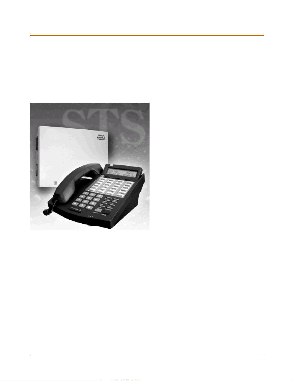
The STS Digital Key Telephone System is a fully digital hybrid Key Telephone System,
designed to meet the telecommunication needs of small to medium-sized business offices.
The system has been designed to allow a high level of software control over the system's
hardware. The software incorporates a vast array of features and capabilities including PC
Database Administration and Least Cost Routing.
Incorporates Command Processing & Voice Switching
The STS System incorporates state of the art digital technology for command processing and
voice switching, using a Pulse Code Modulation/Time Division Multiplexing (PCM/TDM, "A"
law or "U" law) distributed switching matrix.
Supports Multiple Devices
The STS system supports a combination of Digital Keysets and wireless terminals as well as
analog single line devices. With the keysets, commonly used features are activated by direct
button selection. Additionally, many functions may be accessed by dialing specific codes or
optionally, by assigning these dial codes to Flexible Buttons on the keyset. In addition to key
telephones, an array of optional terminals is available.
With the flexibility of the STS extensive feature content, and the capability to use an array of
instruments, the STS can be tailored to meet the short and long term needs of the most
demanding customer requirements.
Page 17

General Description 1-3
Introduction
System Features
This page displays a condensed list of the extensive features available in the STS System:
911 Feature
Account Codes
Answering Machine Emulation
Attendant Assignment / Features
Automatic Privacy
Background Music
Battery Back-Up (Memory)
Baud Rate Assignments
Call Back
Call Coverage
Call Forward
Call Forward - Preset
Calling Forward Override
Calling Station Handsfree Mode Override
Calling Station Tone Mode / Override
Call Park - Station
Call Park - System
Call Pickup
Call Transfer
Camp On
Centrex/PBX
Class Of Service (COS)
CO Line - Access
CO Line Attributes
CO Line DTMF Sending
CO Line Group
CO Line - Identification
CO Line - Incoming Ringing Assignment
CO Line Loop and Pool Buttons
CO Line - Loop Supervision
CO Line - Queue
CO Line - Ringing Options
CO Port Parameters
CO Ring Detect Timer
Conference
Cordless Key Telephone Unit Feature Button
Database Administration
Database Printout (Dump)
Dial By Name
Dial Pulse Sending
Direct Inward System Access (DISA)
Direct Station Selection / Busy Lamp Field
Direct Transfer Mode
Directory Dial
Distinctive Ringing
Do Not Disturb
Executive Override
Executive / Secretary Pairs
External Day Ring
External Night Ring
Fixed Station/Port Number
Flash Rates (Programmable)
Flexible Button Assignment
Flexible Numbering
Group Listening
Headset Mode
Hold - Exclusive
Hold - Preference
Hold - System
Hot Keypad
Hot Line / Ring Down
Hunt Groups
ICLID / Caller ID*
Idle Speaker Mode
Incoming Calling Line Identification
Initializing - System Parameters
Intercom
Inter-Digit Time-Out
Keyset Mode
Last Number Redial
LCD - Contrast
LCD - Display
Least Cost Routing (LCR)
Message Wait
Message Waiting Reminder Tone
Music-On-Hold
Mute Key
Name In Display
Name / Number Translation Table
Night Service
Off-Hook Signaling
Off-Hook Voice Over
Outside Calls
Paging
Pause Timer
PBX Dialing Codes
Personal Messages
Preferred Line Answer
Printing - System Parameters
Privacy Release
Private Line
Recall
Repeat Redial
Relay Programming
Remote Administration*
Remote System Monitor And Maintenance*
Save Number Redial (SNR)
Single Line Telephone (SLT)
Software Version (MBU)
Speakerphone
Speed Dial
Station Attributes
Station Identification
Station Message Detail Recording
Station Relocation
Station Speed Dial Numbers
System Parameters
System Reset
System Speed Bin Access
Text Messaging (Silent Response)
Toll Restriction
Uniform Call Distribution (UCD)
Universal Day/Night Answer
Voice Mail
Voice Mail In-Band Features
Voice Mail One-Touch Recording
Voice Mail Outpulsing Table
Volume Control
* = May require additional hardware or software
Page 18
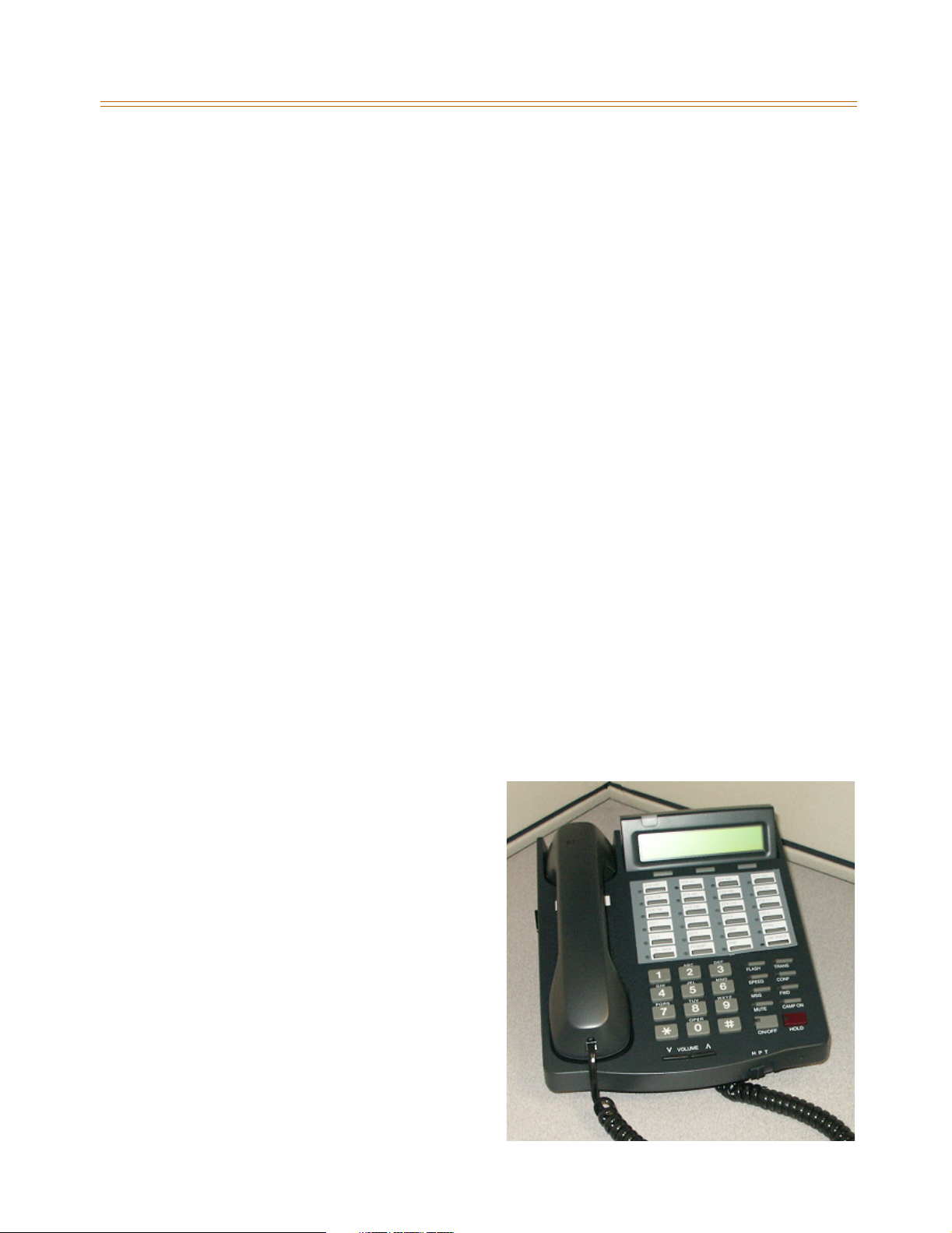
1-4 General Description
Introduction
Digital Keyset Telephones
Each STS System provides all the keys, indicators, and features described.
Handset and Speaker are located at the left side of the front panel. A handset is provided to
allow confidential conversation when desired. Lifting the handset from its cradle (going
off-hook) disengages the station’s built-in speaker. The speaker is located directly below the
center portion of the handset. The station may be operated with the handset on-hook. When
this occurs, audio is transmitted to the station user through the station’s speaker.
Flexible Buttons provide access to idle outside lines, DSS/BLF for internal stations, access
speed dial numbers and activate features. These buttons can be programmed by the
individual station user. The default flexible feature buttons are described as follows:
» CALL BACK button lets you initiate a call back request to another busy station. As soon as
that station becomes idle, the station that left the call back request is automatically
signaled. A flexible button must be assigned to use this feature.
» PICK-UP button lets you pick up a tone ringing intercom call, transferred, incoming, or
recalling outside call to a specific unattended station, by group or directed call pick-up.
» DND (DO NOT DISTURB) button lets the user place their telephone into Do Not Disturb
mode to eliminate incoming outside line ringing, intercom calls, transfers and paging
announcements. The station in DND can use the telephone to make normal outgoing
calls. On Attendant stations, this button becomes the system Night Mode button. A
flexible button must be assigned to use this feature.
» LINE QUEUE button lets you queue to an outside line when all lines in a group are busy.
Your station is placed in queue, awaiting a line in the same group to become available.
Outside Calls are announced by a tone signal repeated every 3.2 seconds. The
corresponding outside line indicator flashes slowly.
Intercom Calls can be tone ringing or voice announced. If voice announced, the receiving
station receives three tone bursts prior to the announcement. If a tone ringing call, the
receiving station hears a tone ring every 2.4 seconds.
24-Button Speakerphone
The 24-button Digital Telephone has 24
flexible, dual color LEDs that can be
customized for each application.
When the flexible button are used as DSS
buttons, station status can be seen in a
single glance. When they are used as CO/
PBX/Centrex buttons, line status is easily
monitored.
This integrated speakerphone offers call
announce with hands-free intercom and a
hot keypad that allows dialing while the
phone is on-hook.
The three interactive soft keys provide
additional feature functionality.
Page 19
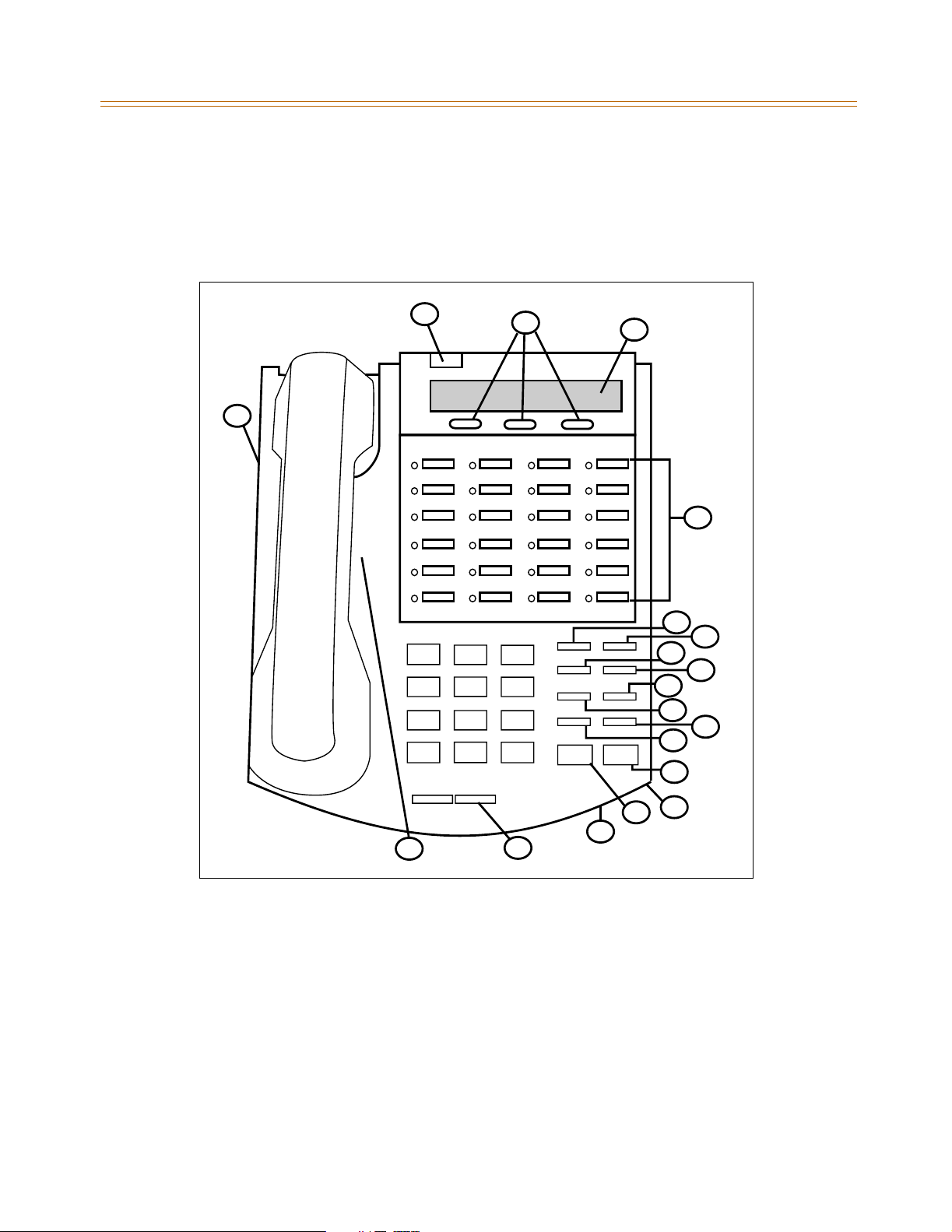
General Description 1-5
Introduction
Digital Keyset/Button Diagram
The following illustration and its corresponding table describe the physical features of the
Vodavi 24-Button Digital Display Telephone. This telephone is necessary when programming
the system features and functions available with the STS System.
2
8
1
1
91
3
9
ABC DEF
123
GHI JKL MNO
456
PRS TUV WXY
789
OPER
*
0
VOLUME
#
FLASH TRANS
SPEED CONF
MSG FWD
CAMP ON
MUTE
HOLD
ON/OFF
13
8
6
7
5
4
10
11
12
16
17
15
14
Figure 1-1: Digital Key Telephone
Page 20

1-6 General Description
Introduction
Table 1-1: Digital Key Telephone Buttons
NUMBER FEATURE BUTTON FUNCTION
1 Display Displays information about telephone status,
dialing directories, and text message
information.
2 Message Indicator Programmable indication for Ring Line, Voice
Mail, Message Wait, or handset operation
3 Flexible Button Keys Used to access outside lines or access call-
handling features.
4 MSG Key Used for Auto-CallBack to a telephone which has
left a text message or to access voice messages.
5 FWD Key Used to forward your calls to another
destination, such as a station or voice mail.
6 SPEED Key Used to access speed dialing, save number redial
and last number redial. This button also is used
to access flexible button programming.
7 CONF Key Used to establish conference calls.
8 TRANS Key Used to transfer an outside call from one station
to another.
9 FLASH Key Used to end an outside call and to restore dial
tone without hanging up receiver.
10 CAMP ON Used to alert a busy station that an outside line is
on hold and waiting for them.
11 MUTE Key Used to activate/deactivate MUTE function.
When activated, the party on the other end
cannot hear you.
12 HOLD Key Used to place outside calls on hold or to retrieve
held calls.
13 ON/OFF Key Used to make a call without lifting the handset.
14 VOLUME Key Used to adjust level of tones, background music,
ringing, receiver volume, and display contrast.
15 Speaker Outputs tones and voice at your extension.
16 Microphone Used to talk with other party without using the
handset.
17 H-T-P Used to select mode of operation: Handsfree,
Tone, or Privacy.
18 Interactive Soft Keys Used to work in conjunction with fixed and
flexible features.
19 Headset Jack 2.5 mm Headset Jack is located on the left side of
the telephone.
Page 21

2
Features and Operation
Detailed descriptions of the System and Station features are presented in alphabetical order.
An abbreviated feature index, that is organized in Flash code numerical sequence, is
provided in Appendix E.
Page 22

2-2 About This Manual
Features and Operation
About This Manual
Content Summary
Chapters
The following chapters contain the descriptions, programming steps, and operating
procedures for the more commonly-used features and functions.
2 - Features & Operation
3 - Attendant Features & Operation
4 - Uniform Call Distribution (UCD)
Appendices
This Appendix contains detailed information on how to use the more complex features
available.
Worksheets and Tables have been placed at the end of this book for easy access to
specific customer system information and frequently-used flash and feature codes.
A - ICLID / Caller ID
B - Least Cost Routing
C - Customer Database Worksheets
D - Quick Reference Tables
Flash Codes
Default Numbering Plan
Part Numbers
Page 23
About This Manual 2-3
Features and Operation
Manual Format & Description
This diagram explains how the Features/Operations are organized in the following chapters
and appendices. The manual format follows the basic outline as shown, but omits those
elements that do not apply to a particular Feature or Operation.
Feature / Operation
Narrative to explain the feature/operation.
Sub-Feature / Operation
Description
Narrative to explain the sub-feature/operation.
Related Information
Quick Reference
¬
Flash XX Button X The xxxx function MUST
also be enabled.
Programming Steps
Consists of those actions required of a system
administrator to program single or multiple phones in
the system or system features using the 24-button digital
telephone.
This section assumes that you have already entered
database administrative programming using the string
.][.
of [
DEFAULT … Shows the system default setting.
][3][2][2][6] (default password).
Operation
Describes how the user operates the digital telephone.
SINGLE LINE TELEPHONE
When the Single Line Telephone operation differs from
the digital telephone, those differences are described.
If your telephone has a FLASH key, use it instead of the
instruction to depress the hookswitch.
Conditions
» Describes any special criteria that affects the
programming or operation of the feature.
Page 24
2-4 911 Feature
Features and Operation
911 Feature
Description
The 911 Feature allows stations in the system to dial 911 without using an access code. 911
calls are placed on 911 marked lines. If all lines are busy, an existing call is dropped and the
911 call is placed.
When this feature is enabled, Trunk Group/LCR Access Code 9 is not available.
Related Information
Quick Reference
¬
Flash 12 To insert [9] for Centrex 911 calls (refer to “PBX Dialing Codes”
Programming Steps
To enable/disable the 911 feature:
on page 2-55).
1. Press the 911 FEATURE flexible button (FLASH 06, Button #13). The following message
displays:
911 FEATURE 0-1
DISABLED
2. Enter a 0 or 1 on the dial pad to enable/disable the use of this feature.
[0] = Disabled
[1] = Enabled
DEFAULT … Disabled
To designate the line(s) for 911 use:
1. Press FLASH and dial [40]. The following message displays:
CO LINE ATTRIBUTES
SELECT A CO LINE RANGE
2. Enter a valid number for the range of lines being programmed. If only one line is being
programmed, enter that number twice (001 001).
If HOLD is pressed without entering a CO range, ALL CO lines are selected.
Page 25

911 Feature 2-5
Features and Operation
3. Press HOLD to save the entry. A confirmation tone sounds and the display updates.
Flexible button #19 (Page A) is lit. The following message displays to indicate current
programming of that line or group of lines:
XXX - XXX PAGE A
ENTER BUTTON NUMBER
XXX-XXX = CO Line Range
4. Press Button #15 to designate the line for 911 use.
911 TRUNK 0-1
DISABLED
5. Enter a 0 or 1 on the dial pad to enable/disable this feature.
[0] = Disabled
[1] = Enabled
6. Press HOLD to save the entry. A confirmation tone sounds and the display updates.
911 Alert
DEFAULT … Disabled
Description
Any station user or attendant who programs a flexible button for 911 ALERT (feature code
608) will be alerted of internal stations placing 911 calls. The system can store the sixteen
most recent 911 calls. Calling information includes the time/date of the call, as well as the
station number from which the call was placed.
The initial 911 Alert indications include:
Audible ringing tone
Green flashing 911 ALERT flexible button LED
Automatic LCD display of 911 call information
E911 CALL XX: STA XXXX
MM/DD/YY HH:MM
XX = Index number (01-16)
Operation
Station users and attendants can press the 911 ALERT flexible button as necessary to view
additional 911 calls’ information in the stored list. After a station user or attendant views the
information for all 911 calls in the system list:
All users’ LEDs change to a solid red indication.
The audible ringing tone at all stations ceases.
The LCDs at all stations revert to a normal display.
Page 26

2-6 911 Feature
Features and Operation
The list remains available for review by pressing the 911 ALERT flexible button as necessary,
until after the messages are deleted.
To delete logged 911 Alert messages:
An attendant uses the following steps to delete the messages on a system-wide basis.
1. Press the 911 ALERT flexible button to display the 911 call information for deletion.
2. Press FLASH to delete that message.
Enhanced 911 Integration
Description
The E911 feature integrates the system to the Proctor PBX ANI-LINK product to provide
enhanced 911 service. Loop Start lines can be connected to the Proctor unit and
programmed to be 911 lines (FLASH 40, Page A, Button #15). When a 911 call is made from a
station in the system, the system will send 911XXXX (XXXX=Station # that placed the 911 call)
in DTMF format to the Proctor. If the station number is less than 4 digits, a leading 0 will
automatically be added. The Proctor unit then accesses a CO trunk and sends the information
in the proper format to the 911 Center.
This feature also provides a means to identify a power failure signal from the Proctor Unit. If a
power failure signal is detected, the KSU routes 911 calls via trunks other than those marked
for 911 use until the signal is removed.
The E911 feature ensures access to 911 by freeing a CO Line, then making a call.
If you are using Centrex lines, a 2-second setting is recommended for Guard Timer
programming (Flash 40, Page C, Button #6). This avoids situations where a line is
seized by the 911 call before an existing call is dropped, causing the emergency call
to be conferenced with the existing call.
Programming Steps
1. Press the ENHANCED 911 button (FLASH 06, Button #14). The following message
displays:
ENHANCED 911 0-1
DISABLED
2. Enter a 0 or 1 on the dial pad to enable/disable the use of this feature.
[0] = Disabled
[1] = Enabled
DEFAULT … Disabled
Conditions
» The 911 Feature (FLASH 06, Button #13) must be enabled for Proctor Integration to work.
» Only the lines connected to the Proctor should have the 911 Enable programmed
(FLASH 40, Page A, Button #15).
» It is recommended to have a power failure procedure in place to ensure that 911 calls are
always routed. Refer to FLASH 09, Button #7 for programming information.
Page 27

Account Codes 2-7
Features and Operation
Enhanced 911 Power Failure Station
Description
The power failure signal is designed to be used with the normally open (NO) power failure
leads from the Proctor unit connected to an SLT port or SLA device. When the leads close in
power failure, this is detected as an off hook and 911 routing ceases to the Proctor unit. 911
calls are sent via trunks other than those marked for 911 use until the power failure lead
opens, which is detected as an on hook. 911 calls are then routed again to the Proctor unit.
Programming Steps
1. Press the E911 POWER FAILURE STATION button (FLASH 09, Button #7). The following
message displays:
PROCTOR 911 P/F ####
####
2. Enter a valid SLT station number (100-8999) to be used as the power failure station.
3. Press HOLD to save the entry. A confirmation tone sounds.
Conditions
» During a power failure, 911 calls are sent via trunks other than those marked for 911.
» During a power failure, the station’s digit information is not sent.
» The feature requires either an SLT port or an SLA port for the integration to work.
Account Codes
Description
An account code is the last field within Station Message Detail Recording (SMDR), that
provides tracking capabilities for specific calls by entering a verified/non-verified, variable
length (up to 12 digits) identifier.
The use of forced Account Codes is optional, offered on a system-wide basis.
Related Information
¬
Flash 21 Button 1 The SMDR function MUST be enabled (refer to “SMDR Enable/
Quick Reference
Disable” on page 2-250).
Page 28

2-8 Account Codes
Features and Operation
Operation
When connected to an outside line call:
1. Press the preprogrammed ACCOUNT CODE button (feature code 627 - refer to “Flexible
Button Assignment” on page 2-149).
2. Dial account code up to 12 digits. (The other party does not hear the digits being dialed).
If account code is less than 12 digits, an [.] must be entered to return to the call.
If account codes are forced, the account code must be entered prior to dialing the
outside number.
SMDR must be enabled for the account code to become part of the SMDR
record.
Account Codes - Forced
Description
The STS allows arranging of the system so that all station users must enter an account code
before placing an outside call.
Account codes can also be used as a Traveling Class-of-Service to upgrade a restricted
station’s class-of-service for unrestricted dialing. Account codes must be entered before the
call when forced.
The system can force account codes on all restricted calls.
When the Forced Account Code option is enabled, and the account code is entered, a
station’s Class of Service is upgraded to day COS1, night COS1.
If option is disabled, a station’s COS is not upgraded but the account code continues to be
part of the SMDR record.
Programming Steps
1. Press ACCOUNT CODES flexible button (FLASH 05, Button #8) to determine whether the
use of Account Codes is forced or optional.
2. Enter a 0 or 1 that corresponds with the following entries:
[0] = Disabled
[1] = Enabled
FORCED ACCOUNT CODE 0-1
DISABLED
3. Press HOLD to save the entry. A confirmation tone sounds.
DEFAULT … Account Codes are optional.
Page 29

Account Codes 2-9
Features and Operation
Operation
Prior to placing an outside line call or during an outside line call:
1. Press the preprogrammed ACCOUNT CODE button.
2. Dial account code up to 12-digits.
If the account code contains fewer than 12 digits, dial [.] to return to the intercom
dial tone.
SMDR must be enabled for the account code to become part of the SMDR record.
Refer to “SMDR Enable/Disable” on page 2-250.
3. Dial [9] or CO Access code. Dial tone sounds.
4. Dial the desired number.
SINGLE LINE TELEPHONE
To enter an Account Code before a call:
1. Lift the handset.
2. Dial [627].
3. Dial the account code.
If the account code contains fewer than 12 digits, dial [.] to return to the intercom
dial tone.
4. Dial [9] or CO Access code. Dial tone sounds.
5. Dial the desired number.
To enter an Account Code during a call:
1. Depress the hookswitch momentarily. Your call will be placed on executive hold while
you enter your account code.
2. Dial [627].
3. Dial the account code.
If the account code contains fewer than 12 digits, dial [.] to automatically return to the call.
Account Codes - Traveling COS (Verified)
Description
The Verified Account Code/Traveling Class of Service (COS) feature provides the ability to
track specific calls by entering a verified, variable length (up to 12 digits) identifier. Each
account code can be assigned a day and night Class of Service for determining the dialing
privileges allowed by that account code.
This feature provides a means for users to override a restricted station. If the dialed account
code matches the Verified Account code table, an intercom dial tone is returned, otherwise
an error tone is presented.
Using verified Account Codes is optional, available on a system-wide basis. SMDR must be
enabled for the account code to print as part of the SMDR record. The STS allows up to 250
12-digit account codes for verification purposes.
Page 30
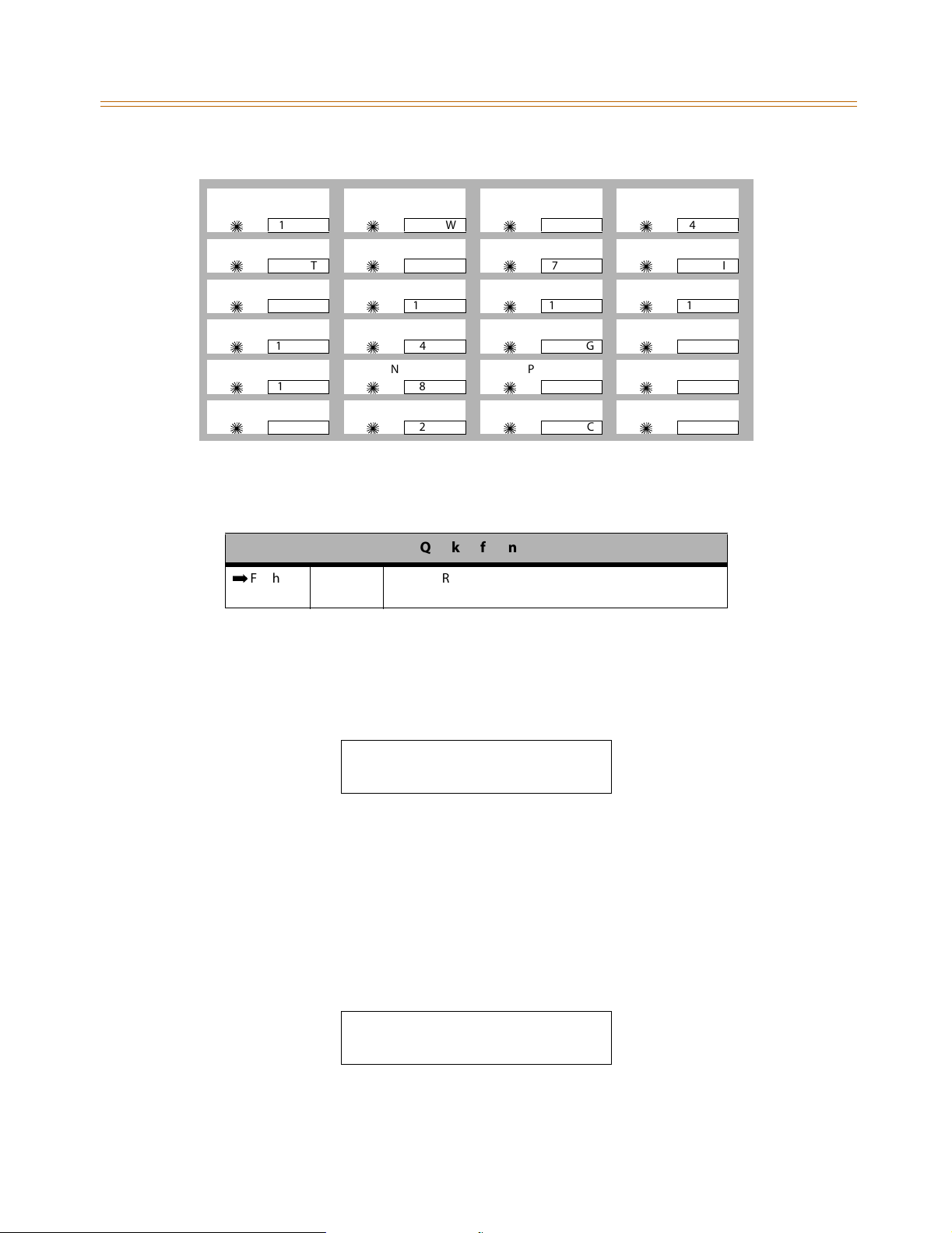
2-10 Account Codes
Features and Operation
ACCT
CODE
5
5
5
5
5
5
1Q
5T
9O
13 D
17 J
21 Z
Figure 2-1: Flash 31 Button Mapping
Related Information
¬
Flash 21 Button 1 The SMDR function MUST be enabled (refer to “SMDR
Programming Steps
CLASS OF
SERVICE
5
5
5
5
5
5
2W
6Y
10 P
14 F
NEXT PREV
18 K
22 X
DELETE ACCT
5
5
5
5
5
5
Quick Reference
Enable/Disable” on page 2-250).
CODE
7U
11 A
15 G
19 L
23 C
3E
5
5
5
5
5
5
ERASE
DIGITS
4R
8I
12 S
16 H
20 ;
24 V
To enable or disable Verified Account Codes:
1. Press the VERIFIED ACCT CODES flexible button (FLASH 06, Button #3). The following
message displays:
VERIFIED ACCT CODES 0-1
DISABLED
2. Enter 0 or 1 on the dial pad to enable/disable Verified Account Codes.
[0] = Disabled
[1] = Enabled
3. Press HOLD to save the entry. A confirmation tone sounds.
DEFAULT … Verified Acct Codes are disabled.
To assign Verified Account Codes:
1. Press FLASH and dial [31]. The following message displays:
ACCT COS
XXXXXXXXXXXX ##
ACCT = Up to 12-digit account code
COS = Class of Service for account codes
Page 31

Account Codes 2-11
Features and Operation
(Refer to Figure 2-1 on page2-10 for FLASH 31 button mapping.)
2. Press the ACCT CODE flexible button (Button #1). Enter up to 12 digits
(0-9, *, #). [*] represents a do not care digit. The system ignores all digits after this digit
when entering an account code. The [#] represents a single do not care digit.
3. Press the CLASS OF SERVICE flexible button (Button #2). Enter a 2-digit Class of Service
Number (1-7) that corresponds to Class of Service 1-7. The first digit represents Day COS
and the second digit represents Night COS.
4. Press HOLD to complete the entry. A confirmation tone sounds.
Existing account code entries display in numerical order from lowest to highest.
If an existing account code displays on the LCD when FLASH 31 is initially entered,
the programming procedure creates a new account code, but does not delete the
account code initially shown. If the intent is to change an existing account code
from one number to another, perform the assignment procedure and delete the
undesired account code entry by following the procedure in the following section.
DEFAULT … No Account Codes are assigned.
To delete the currently displayed Verified Account Code:
1. Press the DELETE CODE flexible button (Button #3) to delete the entire account code
entry.
2. To display the next account code on the LCD, press the NEXT flexible button
(Button #18).
3. To display the previous account code on the LCD, press the PREVIOUS flexible button
(Button #19).
To erase previously entered digits:
1. Press the ERASE DIGITS flexible button (Button #4)
2. Each press of the button erases one digit. Continue until all desired digits are erased.
3. Re-enter the correct digits, then press HOLD to complete the entry. A confirmation tone
sounds.
Operation
To use Verified Account Codes:
1. Press preprogrammed ACCOUNT CODE button before accessing a CO line.
2. Dial the account code up to 12-digits. If the account code matches a verified account
code, intercom dial tone is returned. Otherwise an error tone is presented.
If the account code contains fewer than 12 digits, dial [.] to return to the intercom
dial tone.
SMDR must be enabled for the account code to become part of the SMDR record.
3. Access the outside CO line or dial the LCR code and dial the desired numbers.
Page 32

2-12 Account Codes
Features and Operation
To enter an Account Code before a call:
1. Lift the handset.
2. Dial [627].
3. Dial the account code.
If the Account Code contains fewer than 12 digits, dial [.] to return to the intercom
dial tone.
4. Dial [9] or CO Access code. Dial tone sounds.
5. Dial the desired number.
Conditions
» Verified Account Codes allow use of an account code as a traveling Class of Service.
» If LCR is activated in the system and verified account codes are activated, the user must
enter the account code before dialing the LCR code.
» When verified account codes are activated, station MUST enter an account code to dial a
number that is restricted through station COS and toll restriction. An account code is not
required for calls that are unrestricted through station COS and toll restriction.
» When verified account codes are not forced, a station user may place a call without
entering an account code. In this case, the station user's COS is based on their station
COS. In this case, a user can enter a verified account code to upgrade their COS.
» The Redial feature does not support Verified Account Codes.
» Keyset users must preprogram an ACCOUNT CODE flexible button.
Initialize Verified Account Code Table
Description
The Verified Account Code Table may be initialized to set all data fields to default values.
Table 2-1: Verified Account Code Table Defaults
Program
Code
FLASH 31 VERIFIED ACCOUNT CODES
Flexible
Button
1 Account Code None
2 Class of Service None
3 Delete Code N/A
4Erase Digits N/A
Features
Default Value
(after initialization)
Page 33

Account Codes 2-13
Features and Operation
Programming Steps
1. Press the INITIALIZE ACCT CODES flexible button (FLASH 80, Button #14). The following
message displays:
INITIALIZE ACCT CODES
PRESS HOLD
2. Press the HOLD button. A confirmation tone sounds.
Print Verified Account Codes
Description
The Print Verified Account Codes command dumps the entire database as a permanent
record which can serve as a hardcopy of the database. The system baud rate must match that
of the printer or receiving device.
ACCOUNT CODE TABLE 11
ENTRY
-----
00
01
02
03
04
05
06
07
08
09
10
COS
---
##
##
##
##
##
##
##
##
##
##
##
DGTS
----
12
13
14
15
16
17
18
19
20
21
22
23
24
25
##
##
##
##
##
##
##
##
##
##
##
##
##
##
##
26
27
28
29
30
31
32
33
34
35
36
37
38
39
40
... and so on through 249
##
##
##
##
##
##
##
##
##
##
##
##
##
##
##
Figure 2-2: Verified Account Codes Printout
Programming Steps
1. Press the PRINT ACCT CODES flexible button (FLASH 85, Button #15). The following
message displays:
PRINT ACCT CODES
PRESS HOLD
2. To print the VERIFIED ACCT CODES, press the HOLD button. The following message
displays:
PRINTING ACCT CODES
When the system finishes sending the requested information to the printer, a
confirmation tone sounds.
Page 34

2-14 Answering Machine Emulation
Features and Operation
Answering Machine Emulation
Description
When a call is sent to a voice mailbox, the station associated with that can press a
preprogrammed button to listen to the caller leaving the voice mail message. If the mailbox
owner decides to speak with the caller, the owner can press the preprogrammed button to
be connected to the caller.
Two methods of notification are available, Ring Mode or Speaker Mode. The preprogrammed
button type (654+0=Ring Mode, 654+1=Spkr Mode) defines the operation mode.
EXAMPLE -- Station A user places their phone in the answering machine mode by pressing
the flexible button programmed on the telephone. The button light is solid red. Whatever
button type is assigned on the telephone defines the operation mode of the feature.
When an incoming CO call rings at a station and forwards (except busy type) to the station’s
voice mailbox:
In RING MODE, the preprogrammed answering machine flexible button flashes at
480 ipm red while the caller is in the owner’s mailbox. The mailbox owner presses the
preprogrammed flashing button and the audio is broadcast over the speaker of the
keyset. The mute key is enabled on the keyset at this point. The LED light is solid green.
In SPKR MODE, the voice mail message is broadcast over the speaker. The mute key is
enabled on the keyset and the LED light is solid green.
Display Messages
When a call is ringing the station in ring mode, this message displays:
SCREENING RING
MMM DDYY HH:MM am
When a station is monitoring the caller in VM, this message displays:
SCREENING
MMM DD YY HH:MM am
Answering Machine Emulation only operates on Station No Answer Call Forwarding.
Operation
To set the Operation Mode:
1. Press [SPEED] + [SPEED].
2. Press the desired flexible button for programming.
3. Dial [654] + [0] to select the ring mode or dial [654] + [1] to select the speaker mode.
A confirmation tone sounds.
Page 35

Attendant Assignment/Features 2-15
Features and Operation
The Mailbox Owner has the following options when a call is sent to a voice mailbox:
To leave the caller in the voice mail and stop the speaker broadcast, press the ON/OFF
button. The mailbox owner can continue to listen to the message being left without
taking action at their keyset. When the caller disconnects after leaving the voice mail
message, the button returns to solid red and the keyset returns to idle.
To talk to the party leaving the message, press the MUTE key. The station remains in the
CONF mode, and the caller hears the voicemail and the station user.
To p i ck up the c all , press the ANSWERING MACHINE EMULATION flexible button. When
the call is picked up, the voice mail system disconnects from the call, and the voice mail
port returns to the idle (waiting) state. The caller is in a normal talk state with the CO
caller.
SINGLE LINE TELEPHONE
Answering Machine Emulation cannot be used with Single Line Telephones.
Conditions
» The user must have a digital Keyset.
» Keyset users must preprogram an ANSWERING MACHINE EMULATION flexible button.
» After the in-band digits are sent to the voice mail, the station’s flexible button status is
checked. The feature is executed based on this check. The result of the check is as follows:
Inactive = no feature operation executed
Active = feature executed as per button function (ring mode or speaker mode)
» An idle station can press the flexible button to go to the inactive mode. The LED
extinguishes and no answer machine calls are presented to the station.
» When button is programmed at the station, it is in the inactive mode (LED extinguishes).
» If the station user answers the call, the normal CO line LCD window displays. The call
timer shows the elapsed time including the time the caller was in VM. The call timer does
not start at 0 in this case.
Attendant Assignment/Features
Refer to Chapter 3, Attendant Features and Operation.
Page 36

2-16 Automatic Privacy
Features and Operation
Automatic Privacy
Description
Privacy is automatically provided on all calls. If one station is conversing, another station
cannot intrude on that line.
The Automatic Privacy feature can be disabled, allowing up to seven other stations to join in
on existing CO line conversations. Refer to “Privacy Release” on page 2-216 for details.
Disabling of the privacy feature may be limited by federal, state or local law, so
check the relevant laws in your area before disabling privacy.
Background Music
Description
Each digital telephone user may receive music over their speaker when an optional music
source is connected to the system. The Background Music feature can be allowed or denied
on a system-wide basis by programming. The system can be programmed to let stations
activate their Background Music, in addition to Music-On-Hold.
Programming Steps
1. Press the BACKGROUND MUSIC flexible button (FLASH 05, Button #6).
2. Enter a valid number (0 or 1) that corresponds with the following:
[0] = Disabled or [1] = Enabled
BACKGROUND MUSIC 0-1
ENABLED
3. Press HOLD to save the entry. A confirmation tone sounds.
DEFAULT … Background Music channel is enabled.
Operation
1. Dial [632] on the dial pad or press the preprogrammed flexible button. Enter [1] for ON or
[0] for OFF on the dial pad.
0:OFF 1:CH-1
MMM DD YY HH:MM am
-or-
Use the Soft Key’s BGM option as a toggle to turn background music on or off.
Confirmation tone sounds.
Page 37

Battery Backup (Memory) 2-17
Features and Operation
2. Press the Volume Bar to change the volume. The following message displays:
SPEAKER BGM [#########]
MMM DD YY HH:MM am
SINGLE LINE TELEPHONE
The background music feature is not compatible with single line telephones.
Conditions
» When you pick up the handset or press the ON/OFF button, music automatically
discontinues.
» When the headset is enabled, BGM discontinues.
» A music source must be connected to the BGM/MOH connector.
Battery Backup (Memory)
Description
A lithium battery is located on the Main Board Unit (MBU) to protect system memory in case
of commercial power outage or the system power being turned off for a time period.
Battery Backup Memory retains all system features including system and station speed dial
during a power outage.
Baud Rate Assignments
Description
The two RS-232 connectors on the BKSU can support features such as SMDR, ICLID, or remote
programming.
PORT #1 -- First RS-232C port on the BKSU
PORT #2 -- Second RS-232C port on the BKSU
PORT #3 -- Optional modem
PORT #1
BKSU
5
5
1Q
5T
5
5
PORT #2
BKSU
2W
6Y
5
5
PORT #3
MODEM
3E
7U
5
5
4R
8I
Page 38

2-18 Call Back
Features and Operation
Programming Steps
Press FLASH and dial [15]. The first button is lit and ready for programming Port #1. The
following message displays:
PORT BAUD
1 9600
1. Press the desired PORT # flexible button (Buttons #1, #2, or #3) to select the port to
program.
2. Enter a 1-digit number for the baud rate:
[1] = 150 Baud [5] = 2400 Baud
[2] = 300 Baud [6] = 4800 Baud
[3] = 600 Baud [7] = 9600 Baud
[4] = 1200 Baud
The optional modem (port 3) has a fixed baud rate of 9600.
3. Press HOLD to save the entry. A confirmation tone sounds and the display updates.
DEFAULT . . . Ports #1, #2, and #3 are set at the 9600 baud rate. The highest connection rate
for ports #1 and #2 is 9600 baud, but the system will connect at lower speeds if necessary.
Call Back
The two types of Call Back are Manual Call Back and Automatic Call Back.
Manual Callback
Description
A station can initiate a call back request to another busy station. Once that station becomes
idle, the station that left the call back request is signaled.
Operation
If you dial a telephone that is busy and want to activate Call Back:
1. Press the preprogrammed CALL BACK button or use the Soft Key’s CALL-BK option.
2. Hang up.
When the busy station hangs up, you are signaled.
3. Answer the call; station you called is then signaled. (If your station is busy when signaled,
an automatic MSG is left at your phone).
A Call Back Request is automatically invoked anytime a user listens to the
intercom busy tone for a preset period of time.
Only one Call Back request can be left at a station; the second request is converted
to a message wait call back request.
Page 39

Call Back 2-19
Features and Operation
SINGLE LINE TELEPHONE
If you dial a telephone that is busy and want to leave a Call Back indication:
1. Briefly depress and release the hookswitch.
2. Dial [622] and replace the handset.
Only one Call Back request can be left at a station; the second request will convert
to a message waiting request.
Call Back Button Flash Rate
Description
The Call Back Button flash rate is the rate at which the Call Back button flashes when a station
at which you left a call back request becomes available. This flash rate can be programmed to
29 different options identified in the flash rate table. This enables the programmer to
customize the key system configuration to desired flash rates.
Programming Steps
1. Press the CALL BACK BTN flexible button (FLASH 07, Button #16). The following
message displays:
2. Enter a valid number (00-28) on the dial pad to correspond to one of the 29 available
options (refer to Table 2-14 on page 2-148).
3. Press HOLD to save the entry. A confirmation tone sounds and the display updates.
DEFAULT … Call Back Button flash rate is set for a Red 120 ipm Flash (10).
Automatic Call Back Timer
Description
The Automatic Call Back Timer invokes a call back anytime a user listens to a busy tone for a
programmable period of time. The Automatic Call Back Timer can be set to 00-99 seconds.
A value of 00 disables the timer. An Automatic Call Back does not occur when the timer is
disabled.
Programming Steps
1. Press the AUTO CALL BACK TIMER flexible button (FLASH 01, Button #17). The following
message displays:
CALL BACK BTN 00-28
RED 120 IPM FLASH
AUTO CALL BACK 00-99
03
2. Enter a valid number on the dial pad that corresponds to 00-99 seconds in 1-second
increments.
Page 40

2-20 Call Back
Features and Operation
3. Press HOLD to save the entry. A confirmation tone sounds and the display updates.
DEFAULT … Automatic Call Back Timer is set for 03 seconds (enabled).
Auto Callback - DSS/BLF
Description
The Auto Callback DSS/BLF flash rate is the rate at which a DSS button of a station returning
your call back flashes. This flash rate can be programmed to 29 different options identified in
the flash rate table. This enables the programmer to customize the key system configuration
to desired flash rates.
Programming Steps
1. Press the AUTO CBCK – DSS/BLF flexible button (FLASH 07, Button #7). The following
message displays:
AUTO CBCK DSS / BLF 00-28
RED 120 IPM FLASH
2. Enter a valid number (00-28) on the dial pad to correspond to one of the 29 available
options (refer to Table 2-14 on page 2-148).
3. Press HOLD to save the entry. A confirmation tone sounds and the display updates.
DEFAULT … Auto Callback DSS/BLF flash rate is set for a Red 120 ipm Flash (10).
Message Callback - DSS/BLF Flash Rate
Description
The Message Call Back DSS/BLF flash rate is the rate at which a DSS button of a station
returning your message flashes. This flash rate can be programmed to 29 different options
identified in the flash rate table. This enables the programmer to customize the key system
configuration to desired flash rates.
Programming Steps
1. Press the MSG CBCK / DSS/BLF flexible button (FLASH 07, Button #5). The following
message displays:
MSG CBCK / DSS / BLF 00-28
RED 120 IPM FLUTTER
2. Enter a valid number (00-28) on the dial pad to correspond to one of the 29 available
options (refer to Table 2-14 on page 2-148).
3. Press HOLD to save the entry. A confirmation tone sounds and the display updates.
DEFAULT … Message Callback DSS/BLF flash rate is set for a Red 120 ipm Flutter (11).
Page 41

Call Coverage 2-21
Features and Operation
Call Coverage
Description
The Call Coverage feature provides the functionality for stations to answer calls for other
stations by utilizing call coverage buttons. Visual and Audible status of ringing stations to an
assigned coverage station are provided. Multiple coverage stations can have the same
remote ringing station(s) programmed on their stations. Once a coverage station answers the
call, other stations attempting to answer the call receive a busy tone and the call coverage
button extinguishes on all appearances of that button.
Direct CO calls have ring and LCD priority over call coverage calls. The call coverage station
must have a direct CO appearance or Loop button in order to pick up an external call. If the
call coverage station is in DND, no audible ringing occurs, however visual and LCD
information is presented.
This feature can be programmed by the station user or through admin programming.
DEFAULT … No call coverage buttons are assigned.
Operation
To assign a Call Coverage Button:
1. Press [SPEED] + [SPEED].
2. Press a desired flexible button.
3. Dial [647] for Non-Ringing or [646] for Ringing, followed by the station number to cover. A
confirmation tone sounds.
Once the button is assigned on the station and a call rings in:
1. The coverage station receives a visual indication immediately and an audible indication
for the covered station after a programmable period of time. The ring tone is the internal
ring tone cadence. The flash rate is the same as the incoming CO line ringing rate.
Ringing option = ringing, flashing Call Coverage LED, LCD display as in following
illustration.
CALL FOR STA XXXX
MMM DD YY HH:MM am
Non-Ringing option = flashing Call Coverage LED only (no ringing or change to LCD).
2. The Coverage station user then presses their flashing COVERAGE flexible button,
-or-
Presses the ON/OFF button (only if the ringing option is selected).
Page 42

2-22 Call Coverage
Features and Operation
The call is answered and ceases to ring at any other stations that may have the same
coverage appearance. The following message will display after the call is answered.
CALL FOR STA XXXX
FROM STA YYYY HH:MM am
SINGLE LINE TELEPHONE
This feature can cover SLT extensions, however an SLT cannot perform the call coverage
function. The SLT extension need not be physically installed, only the SLT card must be
installed.
Conditions
» Direct CO calls have ring and LCD priority over call coverage calls. The call coverage
station must have a direct CO appearance or Loop button to pick up an external call. If the
call coverage station is in DND, no audible ringing occurs, however visual and LCD
information is presented.
» This feature can be programmed on any key station or DSS Console with an available
flexible button. If the DSS with a call coverage button assigned is unplugged or moved,
the station associated with that DSS stops ringing until the DSS is plugged in again.
» Only one button type (646 or 647) per covered station can be assigned on a keyset.
Call Coverage Ring Timer
Description
A Call Coverage Ring Timer enables the system administrator to set the amount of delay time
before the call coverage feature provides an audible ring indication at the coverage station.
The call coverage ring timer is a system-wide setting.
The Call Coverage Ring Timer setting is variable from 00-99 seconds.
Programming Steps
1. Press the CALL CVRG RING TIMER flexible button (FLASH 02, Button #3). The following
message displays:
2. Enter a valid number on the dial pad that corresponds to 00-99 seconds.
3. Press HOLD to save the entry. A confirmation tone sounds and the display updates.
DEFAULT … Call Coverage Ring Timer is set for 5 seconds.
CALL COVERAGE RING 00-99
05
Page 43

Call Forward 2-23
Features and Operation
Call Forward
Description
The following sections describe the programming and operation of available call forwarding
options.
Call Forwarding
Description
Stations can be allowed or denied the ability to forward all incoming CO calls, intercom calls,
and transferred outside lines to another station or group.
Use Flash 50 programming when you want to modify a range of stations’ attributes using
fixed station numbers.
Use Flash 51 programming to modify a single station’s attributes using a flexible station
number.
Programming Steps
1. Press FLASH and dial [50] or dial [51]. Flexible button #24 (New Range) is lit and one of
the following messages displays:
Flash 50 - Fixed Numbers Flash 51 - Flexible Numbers
STATION ATTRIBUTES
SELECT A STATION RANGE
2. Enter the range of fixed station numbers (100-149) to be programmed. If only one station
is being programmed, enter that number twice, e.g., [100 100].
If HOLD is pressed without entering a station range, ALL stations are selected.
-or-
Enter a valid flexible number (100-8999) to be programmed.
3. Press HOLD to save the entry. A confirmation tone sounds and the display updates.
Flexible button #19 is lit. The display updates to reflect current programming for Page A:
ENTER STATION NUMBER
Flash 50 - Fixed Numbers Flash 51 - Flexible Numbers
XXX - XXX PAGE A
ENTER BUTTON NUMBER
XXX-XXX = fixed station range XXX = 3- or 4-digit flexible number
SXXX PAGE A
ENTER BUTTON NUMBER
Page 44

2-24 Call Forward
Features and Operation
4. Press the CALL FORWARD flexible button (Button #10). The following message displays:
CALL FORWARD 0-1
ENABLED
5. Enter a 0 or 1 on the dial pad to enable/disable this feature.
[0] = Disabled
[1] = Enabled
6. Press HOLD to save the entry. A confirmation tone sounds.
DEFAULT …Call Forwarding is enabled at all stations.
Conditions
» Only one station at a time can be programmed when using a flexible station number.
» When in Flash 51 programming, if you press HOLD without specifying a flexible number
to be programmed, you will get the station that is in port/station 100.
» Call Forward remains engaged until manually released. When released, the station
number is returned to the LCD.
» Calls cannot be forwarded to a station in the DND mode.
» CO Line queues, a Message Waiting request, and pre-selected messages are canceled
when a station is placed in the Forward mode.
» A Forwarded Call signals to the forwarded station in the Tone mode, regardless of the
Intercom Signaling Switch mode selection.
» A station in the Forward mode can make outgoing calls.
» A station denied the use of Call Forwarding receives an error tone when pressing the
CALL FORWARD button.
» If a CO Line rings into a station with manual Call Forward, the line sequences to the last
station of the chain. If the last station is in DND mode or does not have a Direct
appearance for the CO Line or a Loop button, the call reverts back to the first station.
» If a CO Line rings into a station with both Station and Preset Call Forwarding, Station Call
Forwarding takes precedence. Once the Station Forward determines the station to be
rung as per above, preset Call Forward may then apply at the new station.
» An unlimited number of stations can be set up in a Station Call Forward chain. However, a
station cannot forward to a station that is already a member of their chain.
» If the last number of the Station Call Forward chain is in DND mode, the internal caller
gets a DND response.
» If a private line rings into a station with Manual Call Forward the CO Line forwards,
providing the forwarded station has a direct CO Line appearance or an available Loop
button.
Page 45

Call Forward 2-25
Features and Operation
Call Forward - All Calls
Description
The Call Forward All Calls feature allows a station the ability to have all their calls (internal or
external) forwarded immediately to a designated station, a UCD group pilot number, Voice
Mail group number, Hunt group number, or speed dial bin number for off-net forwarding.
Operation
To activate All Call Forwarding:
1. Lift handset or press ON/OFF button, press the FWD button or dial [640], then dial the All
Calls code [6],
-or-
Use the Soft Key’s ALL-FWD option when in an idle condition.
2. Press DSS button of desired station,
-or-
Dial the desired destination number where to forward calls, including a station number,
UCD group number, Voice Mail, Hunt Group pilot numbers, and speed dial bins for off-net
forwarding.
3. Replace handset; ON/OFF button extinguishes automatically, if used instead of handset.
To remove All Call Forwarding:
1. Lift handset or press ON/OFF button.
2. Either press the FWD button, dial [640] or [662], or use the Soft Key’s CLR-FWD option. A
confirmation tone sounds and the FWD LED extinguishes.
3. Replace handset; ON/OFF button extinguishes automatically, if used instead of handset.
SINGLE LINE TELEPHONE
The SLT operation uses the same procedures as used in Digital Telephone operation
described above, except there is no FWD button or Soft Keys. The user must use the feature
codes as described in the keyset section above.
Conditions
» Conditions are the same as described in the Conditions section of “Call Forwarding” on
page 2-23 plus those noted in the following bullets.
» When in an All Call Forwarding mode, UCD calls cannot be received.
» Calls to a station in both Station Call Forward and DND mode follow the forward.
Page 46

2-26 Call Forward
Features and Operation
Call Forward - Busy
Description
The Call Forward Busy feature allows a station the ability to have their calls forwarded to a
designated station, a UCD group pilot number, Voice Mail group number, or Hunt group
when their station is busy or in DND.
Operation
To activate Busy Call Forwarding:
1. Lift the handset or press ON/OFF button, press the FWD button or dial [640] on the dial
pad, then dial the Call Forward Busy code [8] on the dial pad.
-or-
Use the Soft Key’s BSY-FWD option when in an idle condition.
2. Dial destination number where calls are to be forwarded. Confirmation tone sounds.
3. Replace handset; ON/OFF button extinguishes automatically, if used instead of handset.
To remove Busy Call Forwarding:
1. Lift handset or press ON/OFF button.
2. Either press the FWD button, dial [640] or [662], or use the Soft Key’s CLR-FWD option. A
confirmation tone sounds and the FWD LED extinguishes.
3. Replace handset; ON/OFF button extinguishes automatically, if used instead of handset.
SINGLE LINE TELEPHONE
The SLT operation uses the same procedures as used in Digital Telephone operation
described above, except there is no FWD button or Soft Keys. The user must use the feature
codes as described in the keyset section above.
Conditions
» Conditions are the same as described in the Conditions section of “Call Forwarding” on
page 2-23 plus those noted in the following bullets.
» Calls to a station in both Station Call Forward and DND mode follow the forward.
Call Forward - Busy / No Answer
Description
The Call Forward Busy / No Answer feature allows a station the ability to forward a
combination busy / no answer calls to a designated station, a UCD group pilot number, Voice
Mail group number, or Hunt group. No answer calls forward when the system-wide no
answer timer expires. Initial CO ringing, transferred CO ringing and intercom ringing calls can
all be forwarded. Calls that ring to an idle station is call forwarded after expiration of the No
Answer Ring Timer.
Page 47

Call Forward 2-27
Features and Operation
Operation
To activate Busy / No Answer Call Forwarding:
1. Lift the handset or press ON/OFF button, press the FWD button or dial [640] on the dial
pad, then dial the Call Forward Busy/No Answer code [9] on the dial pad.
-orUse the Soft Key’s B/NA-FWD option when in an idle condition.
2. Dial the desired destination number where calls are to be forwarded. A confirmation tone
sounds.
3. Replace handset; ON/OFF button extinguishes automatically, if used instead of handset.
To remove Busy / No Answer Call Forwarding:
1. Lift handset or press ON/OFF button.
2. Either press the FWD button, dial [640] or [662], or use the Soft Key’s CLR-FWD option. A
confirmation tone sounds and the FWD LED extinguishes.
3. Replace handset; ON/OFF button extinguishes automatically, if used instead of handset.
SINGLE LINE TELEPHONE
The SLT operation uses the same procedures as used in Digital Telephone operation
described above, except there is no FWD button or Soft Keys. The user must use the feature
codes as described in the keyset section above.
Conditions
» Conditions are the same as described in the Conditions section of “Call Forwarding” on
page 2-23 plus those noted in the following bullets.
» ICM calls forwarded to a VM group receive ringback until a member of the VM group
becomes available.
» If a station is denied Station Call Forwarding, then Off-Net Forwarding is not allowed.
» The No Answer Timer is controlled on an individual basis in Flash 50, Page C, Button #5 for
manual forwarding and preset forwarding.
Call Forward - Follow Me
Description
The Follow Me feature lets a user who is away from their station, activate/deactivate call
forwarding from another station in the system. This lets the user forward their calls to their
current location or into Voice Mail, UCD, Hunt Groups, any other station in the system, or to
an off-net location. When this call forward is activated, all calls presented to the forwarded
station forward to the destination station immediately.
Operation
To activate Follow Me Call Forwarding:
1. Lift the handset or press ON/OFF button.
2. Dial the Follow Me Forward code [642] on the dial pad.
3. Dial station number of the station from which forwarding is desired.
Page 48

2-28 Call Forward
Features and Operation
4. Dial the appropriate forwarding condition code.
.
[6] = All Calls [8] = Busy [
[7] = No Answer [9] = Busy/No Answer
5. Dial the three- or four-digit destination number where calls are to be forwarded (Station,
Voice Mail, UCD or Hunt Group, or speed bin (only for off-net)). A confirmation tone
sounds.
6. Replace handset; ON/OFF button extinguishes automatically, if used instead of handset.
To remove Follow Me Call Forwarding:
1. Lift the handset or press ON/OFF button.
2. Dial the Follow Me Forward code [642] on the dial pad.
3. Dial the station number of the station that forwarding is to be cancelled.
4. Dial [6] (regardless of the forward condition).
5. Redial the same station number. Confirmation tone sounds and FWD LED extinguishes.
To establish Follow Me Call Forwarding (off-site location):
1. Dial into the system on a DISA or TIE trunk. Enter the DISA access code, if applicable.
2. Dial the Follow Me Forward code [642] on the dial pad.
3. Dial the station number of the station from which forwarding is desired.
4. Dial the appropriate forwarding condition code.
[6] = All Calls [8] = Busy [
[7] = No Answer [9] = Busy/No Answer
5. Dial the three- or four-digit destination number where calls are to be forwarded (System
Speed Bin (only for off-net), Station, Voice Mail, UCD or Hunt Groups). A confirmation
tone sounds; five seconds later a dial tone is received.
] = Off-Net
.
] = Off-Net
To remove Follow-me Call Forwarding (off-site location):
1. Dial into the system on a DISA or TIE trunk. Enter the DISA access code, if applicable.
2. Dial the Follow-Me Forward code [642] on the dial pad.
3. Dial the station number of the station that forwarding is to be cancelled.
4. Dial [6] (regardless of the forward condition).
5. Redial the same station number. Confirmation tone sounds; 5 secs later = dial tone.
Conditions
» If a Call Forward mode is currently active at the station where forwarding is desired, the
new forward becomes active and cancels the previous forward.
» Both internal and external calls to the affected station forward to the designated location.
» Call forwarding must be allowed in programming for the affected station.
» When remote forward is activated, the forwarding is immediate.
» A station’s Call Forward status is stored in a battery protected area of memory. A station’s
Call Forward status is returned after a power failure or system reset occurs.
Page 49

Call Forward 2-29
Features and Operation
» When a key telephone is forwarded remotely, the key station’s forward button lights. The
station user may cancel the forwarding at their station by pressing ON/OFF, then the FWD
button. SLT users can cancel their forwarding by going off hook and dialing the forward
code.
» DISA callers entering the code and making a mistake are given error tone for 3 seconds,
silence for 2 seconds, then the dial tone is returned.
Call Forward - No Answer
Description
The Call Forward No Answer feature allows a station the ability to have their calls forwarded
to a designated station, a UCD group pilot number, Voice Mail group number or Hunt group
number when there is no answer at the station. No answer calls forward when the No Answer
Timer expires.
Operation
To activate No Answer Call Forwarding:
1. Lift the handset or press ON/OFF button, press the FWD button or dial [640] on the dial
pad, then dial the Call Forward No Answer code [7] on the dial pad.
-or-
Use the Soft Key’s N/A-FWD option when in an idle condition.
2. Dial the desired destination number where calls are to be forwarded. A confirmation tone
sounds.
3. Replace handset; ON/OFF button extinguishes automatically, if used instead of handset.
To remove No Answer Call Forwarding:
1. Lift handset or press ON/OFF button.
2. Either press the FWD button, dial [640] or [662], or use the Soft Key’s CLR-FWD option. A
confirmation tone sounds and the FWD LED extinguishes.
3. Replace handset; ON/OFF button extinguishes automatically, if used instead of handset.
SINGLE LINE TELEPHONE
The SLT operation uses the same procedures as used in Digital Telephone operation
described above, except there is no FWD button or Soft Keys. The user must use the feature
codes as described in the keyset section above.
Conditions
» Conditions are the same as described in the Conditions section of “Call Forwarding” on
page 2-23 plus those noted in the following bullets.
» A Camp On signal is allowed at the forwarded station if that station is busy.
» Idle keyset in handsfree mode does not follow no answer forwarding for internal calls.
» The No Answer Timer is controlled on an individual basis in Flash 50, Page C, Button #5 for
manual forwarding and preset forwarding.
Page 50

2-30 Call Forward
Features and Operation
Call Forward - External (Off-Net)
Description
Stations are allowed to forward intercom and transferred CO line calls to an off-net location.
The Call Forward Off-Net feature allows a station to reroute calls that would normally be lost.
Calls can be forwarded to home or another off-net site. Initially-ringing CO calls cannot be
forwarded with this feature.
Operation
To activate Off-Net Call Forwarding:
1. Lift handset or press ON/OFF button.
2. Press the FWD button or dial [640] on the dial pad.
.
3. Dial [
contains the number where calls are to be forwarded. A confirmation tone sounds and
the FWD button LED is Red Steady On.
4. Replace handset; ON/OFF button extinguishes automatically, if used instead of handset.
To remove Off-Net Call Forwarding:
] on the dial pad. Dial the speed bin number (9000-9019 or 9020-9099) that
1. Lift handset or press ON/OFF button.
2. Press the FWD button or dial either [640] or [662]. A confirmation tone sounds and the
FWD LED extinguishes.
3. Replace handset; ON/OFF button extinguishes automatically, if used instead of handset.
SINGLE LINE TELEPHONE
The SLT operation uses the same procedures as used in Digital Telephone operation
described above, except there is no FWD button. The user must use the feature codes as
described in the keyset section above.
Conditions
» Forwarding is unconditional and occurs immediately when a station calls an Off-Net
forwarded station.
» The call to a station is not answered until the outgoing CO Line is seized and the digits are
out-pulsed. The calling Station receives ICM ringback until answered. Upon answer, the
Station receives whatever CO progress tones apply (Ringback, Busy, Error,
Announcement, etc.).
» If a station is denied Station Call Forwarding, Off-Net forwarding is not allowed.
» Toll Restriction is based on the forwarding station’s COS and the outgoing CO Line COS.
» The calling station must have an appearance (Direct, Loop) for the outgoing (Off-Net)
line. The call is not forwarded if a Direct Appearance or LOOP key is unavailable.
» SMDR printout reflects transferred and outgoing calls like a DISA call record.
» Station users may use a Station or System Speed Dial Bin for Station Off-Net Forward.
» Call must be an intercom or transferred CO call.
» The attendant station must have access to the CO Line group used in the speed bin for
the off-net forward to work.
Page 51

Call Forward 2-31
Features and Operation
Call Forward Button Flash Rate
Description
The Call Forward Button flash rate is the rate at which the Call Forward button flashes when
any type of forward mode is used. This flash rate can be programmed to 29 different options
identified in the flash rate table. This enables the programmer to customize the key system
configuration to desired flash rates.
Programming Steps
1. Press the CALL FORWARD BTN flexible button (FLASH 07, Button #3). The following
message displays:
CALL FORWARD BTN 00-28
RED STEADY ON
2. Enter a valid number (00-28) on the dial pad to correspond to one of the 29 available
options (refer to Table 2-14 on page 2-148).
3. Press HOLD to save the entry. A confirmation tone sounds and the display updates.
DEFAULT … Call Forward Button flash rate is set for a Red Steady On (01).
Call Forward Display
Description
When any type of station call forwarding is invoked, the LCD display normally indicates the
call forwarding mode at all times. This feature has modified the LCD forwarding display to
make the call forwarding mode display optional. This feature is enabled/disabled in admin
programming on a system-wide basis. The call forward status is stored in a battery protected
area of memory.
Programming Steps
1. Press the CALL FWD DISPLAY STATUS flexible button (FLASH 06, Button #4).
2. Enter a 0 or 1 on the dial pad to enable/disable Call Forward Display.
[0] = Disabled
[1] = Enabled
3. Press HOLD to save the entry. A confirmation tone sounds.
CALL FWD DISPLAY 0-1
ENABLED
DEFAULT … Call Forward Display is enabled.
Page 52

2-32 Call Forward - Preset
Features and Operation
Call Forward - Preset
Description
The Call Forward Preset feature allows the system database to be configured so that
incoming CO Lines, which are programmed to ring at a particular station, can be forwarded
elsewhere in the system predetermined by programming. This feature is active if the station
ringing is not answered in a specified time, and is particularly useful in overflow applications
in which a Voice Mail or Auto Attendant may be in use.
The following Call Forward - Preset types are detailed in the next several sections:
Preset Call Forward - Voice Mail, UCD, or Hunt Groups -- CO Lines can be Preset
Forwarded to ring to one of the group types in the system (Hunt, Voice Mail, or UCD).
Each time the Preset Forward Timer expires (a total of 5 attempts), the group is checked
for an idle station.
Preset Call Forward - Off-Net -- CO Lines can be preset forwarded to ring Off-Net via
speed dial from any station. After the expiration of the preset forward timer, the system
selects an idle CO line, dials the off-net location, then connects the two CO lines.
Preset Call Forward - Per CO Line -- The Preset Call Forward feature allows each CO line
to be preset call forwarded on a per CO line basis. This allows a CO line to initially ring at
multiple stations and forward to a predetermined destination. The destination can be a
station or Hunt Group. Each CO line has a Preset Forward Timer. Each CO line also has a
VMID field to allow specific VM digits to be sent when a CO line forwards to a VM group.
Feature applies to initial CO ringing lines only.
If a forward destination is programmed in the CO line field, the CO call forwards to
that destination after the CO Preset Forward timer expires. This forward occurs
regardless of how many or how few stations the line is ringing on. Once the CO line is
answered and transferred, station call forwarding rules are in effect.
Calls still follow all call or busy forwards, however, CO preset forward forwards the call
if the first forward destination has not answered the call. VMID digits per CO line
override station VMID. Calls ringing into UCD or VM Groups continue to ring the
group. The CO call does not forward when ringing one of these types of groups.
Preset Call Forward - Stations -- Each station user may have Preset Call Forward in the
database to direct incoming, transferred, as well as intercom calls to other destinations in
the system. The system allows for different destinations based on a Busy or a No Answer
condition, as wells as internal versus external (CO) call.
Page 53

Call Forward - Preset 2-33
Features and Operation
Preset Call Forward - Station
Description
The Preset Call Forward feature provides separate Busy and No Answer destinations for
internal and external calls with a No Answer Timer associated to each station. External calls
ringing that particular station, transferred calls, and internal calls follow this Preset Forward
feature.
Valid destination entries are:
System Speed Bin Numbers
Flexible Station Numbers
Flexible Voice Mail Group Numbers
Flexible Hunt Group Numbers
Flexible UCD Group Numbers
Use Flash 50 programming when you want to modify a range of stations’ attributes using
fixed station numbers.
Use Flash 51 programming to modify a single station’s attributes using a flexible station
number.
Programming Steps
To program internal and external calls with separate Busy and No Answer destinations,
perform the following steps.
1. Press FLASH and dial [50] or dial [51]. Flexible button #24 (New Range) is lit and one of
the following messages displays:
Flash 50 - Fixed Numbers Flash 51 - Flexible Numbers
STATION ATTRIBUTES
SELECT A STATION RANGE
2. Enter the range of fixed station numbers (100-149) to be programmed. If only one station
is being programmed, enter that number twice, e.g., [100 100].
If HOLD is pressed without entering a station range, ALL stations are selected.
-or-
Enter a valid flexible number (100-8999) to be programmed.
3. Press HOLD to save the entry. A confirmation tone sounds and the display updates.
Flexible button #19 is lit. The display updates to reflect current programming for Page A:
ENTER STATION NUMBER
Flash 50 - Fixed Numbers Flash 51 - Flexible Numbers
XXX - XXX PAGE A
ENTER BUTTON NUMBER
XXX-XXX = fixed station range XXX = 3- or 4-digit flexible number
SXXX PAGE A
ENTER BUTTON NUMBER
Page 54

2-34 Call Forward - Preset
Features and Operation
4. Press button #21. The display updates to reflect current programming for Page C.
Flash 50 - Fixed Numbers Flash 51 - Flexible Numbers
XXX - XXX PAGE C
ENTER BUTTON NUMBER
XXX-XXX = fixed station range XXX = 3- or 4-digit flexible number
SXXX PAGE C
ENTER BUTTON NUMBER
Internal No Answer Destination
1. Press Button #1. The following message displays:
INTERNAL NO ANSWER FWD
####
2. Enter a valid flexible destination number and press HOLD.
3. To delete the entry, press the [#] key and then press HOLD.
Internal Busy Destination
1. Press Button #2. The following message displays:
INTERNAL BUSY FWD
####
2. Enter a valid flexible destination number and press HOLD.
3. To delete the entry, press the [#] key and then press HOLD.
External No Answer Destination
1. Press Button #3. The following message displays:
EXTERNAL NO ANSWER FWD
####
2. Enter a valid flexible destination number and press HOLD.
3. To delete the entry, press the [#] key and then press HOLD.
External Busy Destination
1. Press Button #4. The following message displays:
EXTERNAL BUSY FWD
####
2. Enter a valid flexible number and press HOLD.
3. To delete the entry, press the [#] key and then press HOLD.
Page 55

Call Forward - Preset 2-35
Features and Operation
No Answer Timer
1. Press Button #5. The following message displays:
NO ANSWER TIMER 00-99
10
2. Enter a valid number (00-99) and press HOLD (00=disable).
DEFAULT … No Answer Timer is set at 10 seconds.
Conditions
» The No Answer Timer controls both Manual and Preset Forwarding (feature code 640
forwarding and FLASH 50, Page C, Buttons #1-4.
» Station Forwarding overrides the Preset Forward settings.
» Only one station at a time can be programmed when using a flexible station number.
» When in Flash 51 programming, if you press HOLD without specifying a flexible number
to be programmed, you will get the station that is in port/station 100.
Preset Call Forward - CO Line
Description
The Preset Call Forward Destination feature enables a CO line to initially ring at multiple
stations and forward to a pre-determined destination. The destination can be a station
(DKT-SLT), Voice Mailbox, UCD group, or Hunt group. Each CO line has a Preset Forward
Timer. Each CO line also has a VMID field to allow sending of specific VM digits when a CO line
forwards to a VM group. Calls ringing into UCD Groups or Voice Mail Groups continue to ring
the group. The CO line does not forward when ringing one of these types of groups.
Programming Steps
1. Press FLASH and dial [40]. The following message displays:
CO LINE ATTRIBUTES
SELECT A CO LINE RANGE
2. Enter a valid number for the range of lines being programmed. If only one line is being
programmed, enter that number twice (001 001).
If HOLD is pressed without entering a CO range, ALL CO lines are selected.
3. Press HOLD to save the entry. A confirmation tone sounds and the display updates.
Flexible Button #19 (Page A) is lit.
4. Press the Page B flexible button (Button #20). The following message displays:
XXX - XXX PAGE B
ENTER BUTTON NUMBER
XXX-XXX = CO Line Range
Page 56

2-36 Call Forward - Preset
Features and Operation
5. Press the PRESET FWD DESTINATION flexible button (Button #5). The following message
displays:
PRESET FORWARD DEST
####
6. Enter a valid forward destination on the dial pad.
[9020-9099] = System Speed Bins
[100-149] = Station Extensions
[440-447] = Voice Mail Groups 1-8
[450-457] = Hunt Groups 1-8
[550-557] = UCD Groups 1-8
7. Press HOLD. A confirmation tone sounds and the LCD display updates.
DEFAULT … No destinations are assigned.
Preset Forward Voice Mail ID
Description
The Preset Forward Voice Mail ID feature allows a programmer to assign which digits are sent
to voice mail when a CO line is programmed to Preset Forward.
Programming Steps
1. Press the PRESET FWD VMID flexible button (FLASH 40, Page B, Button #6). The
following message displays:
PRESET FORWARD VMID 0-9999
####
2. Enter a valid number on the dial pad that corresponds to 0-9999 for Voice Mail ID digits.
3. Press HOLD to complete the entry. A confirmation tone sounds and the display updates.
To delete numbers currently entered:
1. Press [#] button four times.
2. Press the HOLD button to update (all information is erased).
DEFAULT … No digits are sent.
Page 57

Call Forward - Preset 2-37
Features and Operation
Preset Forward Timer (Incoming Call to a Destination)
Description
The Preset Forward Timer determines the time an outside line rings before being forwarded
to a predetermined destination as programmed in FLASH 40, Page C, Button #8. If a forward
destination is programmed in the CO line field, the CO calls forward to that destination after
the CO preset forward timer expires. This forward occurs regardless of how many stations the
line is ringing.
This feature applies to initial CO ringing lines only and works with Preset Forward CO Line
assignments. The CO Line Preset Forward Timer setting is variable from 00-99 seconds. A [00]
entry disables the timer and the feature is disabled.
Programming Steps
1. Press FLASH and dial [40]. The following message displays:
CO LINE ATTRIBUTES
SELECT A CO LINE RANGE
2. Enter a valid number for the range of lines being programmed. If only one line is being
programmed, enter that number twice (001 001).
If HOLD is pressed without entering a CO range, ALL CO lines are selected.
3. Press Button #21 to select Page C. The display updates. The following message displays to
indicate current programming of that line or group of lines:
XXX - XXX PAGE C
ENTER BUTTON NUMBER
XXX-XXX = CO Line Range
4. Press the PRESET FWD TIMER flexible button (Button #8). The following message
displays:
PRESET FWD TIMER 00-99
10
5. Enter valid number on dial pad which corresponds to 00–99 seconds.
6. Press HOLD to save the entry. A confirmation tone sounds and the display updates.
DEFAULT … CO Line Preset Forward Timer is set at 10 seconds.
Page 58

2-38 Calling Forward Override
Features and Operation
Calling Forward Override
Description
The Call Forward Override feature allows a user to reach a station that is call forwarded. This
allows the calling station to override the forwarding which allows the user to use Off Hook
Voice Over (OHVO), Executive Override, Monitor, Message Wait Indication, Camp On, or Call
Back Request at that station rather than forwarding to another destination.
Operation
1. Dial [5#] followed by the desired station extension.
2. Press the appropriate preprogrammed button.
Call Back = [622]
Camp On = [620]
Executive Override = [625]
Message Wait = [623]
OHVO = [628]
Calling Station Handsfree Mode Override
Description
Enables a calling station to override a called station’s T intercom setting.
Operation
When placing a call to a station and handsfree is desired:
1. Dial [7#] on the dial pad.
2. Dial the extension number,
-or-
Press DSS button of desired station (call connects to the station in handsfree mode).
Calling Station Tone Mode Override
Description
Enables a calling station to override a called station’s H or P intercom settings.
Operation
When placing a call to a station and tone ringing is desired:
1. Dial [6#] on the dial pad.
2. Dial the extension number,
-or-
Press DSS button of desired station (call tone rings station).
Page 59

Call Park 2-39
Features and Operation
Call Park
Call Park - System
Description
An outside line can be placed into one of eight system park locations and can be retrieved by
any station that has a direct line appearance or an available Loop button. Parked calls have
their own recall timer that recalls the originating station, and if still unanswered, the
Attendant(s). An outside line may also be placed into a station park location. The station user
then dials a code followed by their station number to retrieve the call.
Operation
To consult, page, or call an internal party while connected to an outside line:
1. Press the preprogrammed CALL PARK flexible button. A confirmation tone sounds.
-orPress TRANS button. The caller is put on hold. Dial parking location (430 to 437). A
confirmation tone sounds.
2. If busy tone is received, press TRANS once to reconnect with the caller. Press TRANS again
and dial another park location or press another CALL PARK flexible button for a different
parking location.
Call Park Pickup - System
To retrieve a Parked Call, either:
1. Lift handset or press ON/OFF button.
2. Press [#].
3. Dial the parking location (430 to 437) where the call was parked or press the
preprogrammed CALL PARK flexible button for that park location.
-or-
Use the Soft Key’s PK-PICK1 option when in an idle condition (to pick up group 1 only).
SINGLE LINE TELEPHONE
To place an outside call on hold and consult with, page, or call an internal party before
transferring the outside call:
1. Depress and release the hookswitch. The caller is put on Exclusive Hold.
2. Dial parking location (430 to 437). A confirmation tone sounds.
3. If busy, depress and release hookswitch twice, dial another park location, then hang up.
To retrieve a parked call:
1. Lift the handset.
2. Press the [#] button.
3. Dial parking location (430 to 437) where the call was parked.
Page 60

2-40 Call Park
Features and Operation
Conditions
» Intercom calls cannot be parked on system park locations (430-437); intercom calls can
be parked using the personal park location.
» A CO call parked in a system call park location recalls to the station that parked the call,
when the call park recall timer expires. The CO call rings to this station until the system
hold timer expires. The CO call then recalls the Attendant (both the Attendant and
initiating stations are ringing), and the Attendant recall timer is initiated. When the
Attendant recall timer expires, the CO call is disconnected.
Call Park Recall Timer
Description
The Call Park Recall Timer determines the time before a call placed in a Call Park location
recalls the station placing the call in park. If unanswered by that station, the call recalls the
attendant.
The Call Park Recall Timer setting is variable from 000–600 seconds. A 000 entry disables the
timer and there is no recall.
Programming Steps
1. Press the CALL PARK RECALL TIMER flexible button (FLASH 01, Button #8). The following
message displays:
2. Enter a valid number on the dial pad that corresponds to 001-600 seconds.
3. Press HOLD to save the entry. A confirmation tone sounds and the display updates.
DEFAULT … Call Park Recall Timer is set at 180 seconds.
Call Park - Personal
Description
Each telephone in the system can place a call into a personal park location and then later
retrieve that call from the originating station. Intercom calls and CO line calls can be placed
into the stations’ personal park location. Calls parked in a personal park location are subject
to the system call park recall timer (refer to “Call Park Recall Timer” on page 2-40). A station
retrieving a personal parked CO call must have either a direct CO line appearance or an
available loop button to retrieve the parked call.
CALL PARK TIMER 000-600
180
Only one call can be parked in a Personal Call Park location at one time. When
dialing the Personal Park location and the location is already occupied, the
initiating station receives the previously parked call and the second call is then
parked.
Page 61

Call Park 2-41
Features and Operation
Operation
To park a call, while connected to an outside line:
1. Press the TRANS button. The caller is put on Exclusive Hold.
2. Dial the Personal Park location [438] on the dial pad,
-or-
Press the preprogrammed PERSONAL PARK button.
Dial tone sounds.
To retrieve a parked call:
Dial the Personal Call Park location code [438] on the dial pad,
-or-
Press the preprogrammed PERSONAL PARK button.
A talk path is established between the two parties.
SINGLE LINE TELEPHONE
While connected to first call:
1. Depress the hookswitch momentarily. Intercom dial tone sounds.
2. Dial [438]. Call is placed in personal park.
3. Dial desired number for second call.
4. Depress the hookswitch momentarily. Intercom dial tone sounds.
5. Dial [438]. The first call is returned and the second call is placed into personal park.
The user can alternately connect to the other call by doing a hook flash and dialing
[438] as many times as necessary.
Conditions
» Intercom calls and CO line calls can be placed into the station's personal park location.
» Calls parked in a personal park location are subject to the system call park recall timer.
» A CO call parked in a personal call park location recalls to the station that parked the call,
when the call park recall timer expires. The CO call rings to this station until the system
hold timer expires. The CO call then recalls the Attendant (both the Attendant and
initiating stations are ringing), and the Attendant recall timer is initiated. When the
Attendant recall timer expires, the CO call is disconnected.
Page 62

2-42 Call Park
Features and Operation
Call Park - Station
Description
Call park (by station number) allows calls to be parked at a station other than you own, thus
allowing for expanded park locations.
Operation
To create a CALL PARK (Station) button:
1. Press [SPEED] + [SPEED].
2. Press the desired flexible button.
3. Dial [439] + [#]. A confirmation tone sounds.
While connected to an outside line:
1. Press the TRANS button.
2. Dial [439] + [XXX] (XXX = station number).
-or-
1. Press the TRANS button.
2. Press the preprogrammed CALL PARK (Station) button.
3. Dial [XXX] (XXX = station number).
To retrieve a Call Park (Station) call:
Dial [#6] + [XXX] while at any telephone in the system, including the initiator’s. [XXX] = the
station number used to park the call.
-or-
Dial [438] from the initiator’s station.
SINGLE LINE TELEPHONE
The SLT operation uses the same procedures as used in Digital Telephone operation
described above, except there is no TRANS button. The user must use hookflash before
dialing feature code 439.
Conditions
» Only one call can be in a park location at a time. Multiple calls to the same station park
location is not possible.
» The #6 code is flexible and can be assigned in Flash 52 programming.
» The call will be placed in the Station’s Personal Park location.
Page 63

Call Pickup 2-43
Features and Operation
Call Pickup
Description
Stations are assigned to pickup groups. Stations can be in any combination of the eight
groups or in no group at all.
A station can pickup a call ringing to any specific unattended station by using the Directed
Call Pickup procedure.
A station can pickup a call ringing to an unattended station within the same UCD group by
using the Group Call Pickup Procedure.
Use Flash 50 programming when you want to modify a range of stations’ attributes using
fixed station numbers.
Use Flash 51 programming to modify a single station’s attributes using a flexible station
number.
Programming Steps
1. Press FLASH and dial [50] or dial [51]. Flexible button #24 (New Range) is lit and one of
the following messages displays:
Flash 50 - Fixed Numbers Flash 51 - Flexible Numbers
STATION ATTRIBUTES
SELECT A STATION RANGE
ENTER STATION NUMBER
2. Enter the range of fixed station numbers (100-149) to be programmed. If only one station
is being programmed, enter that number twice, e.g., [100 100].
If HOLD is pressed without entering a station range, ALL stations are selected.
-or-
Enter a valid flexible number (100-8999) to be programmed.
3. Press HOLD to save the entry. A confirmation tone sounds and the display updates.
Flexible button #19 is lit. The display updates to reflect current programming for Page A:
Flash 50 - Fixed Numbers Flash 51 - Flexible Numbers
XXX - XXX PAGE A
ENTER BUTTON NUMBER
XXX-XXX = fixed station range XXX = 3- or 4-digit flexible number
SXXX PAGE A
ENTER BUTTON NUMBER
Page 64

2-44 Call Pickup
Features and Operation
4. Press button #20. The display updates to reflect current programming for Page B.
Flash 50 - Fixed Numbers Flash 51 - Flexible Numbers
XXX - XXX PAGE B
ENTER BUTTON NUMBER
XXX-XXX = fixed station range XXX = 3- or 4-digit flexible number
SXXX PAGE B
ENTER BUTTON NUMBER
5. Press the GROUP PICKUP flexible button (Button #5). The following message displays:
PICKUP GROUPS 0-8
1
6. Enter a valid number (1-8) to program Pickup Groups.
[0] = No Group [5] = Group 5
[1] = Group 1 [6] = Group 6
[2] = Group 2 [7] = Group 7
[3] = Group 3 [8] = Group 8
[4] = Group 4
7. Press HOLD to save the entry. A confirmation tone sounds and the display updates.
DEFAULT … All stations are in Group 1.
Conditions
» Only one station at a time can be programmed when using a flexible station number.
» When in Flash 51 programming, if you press HOLD without specifying a flexible number
to be programmed, you will get the station that is in port/station 100.
Directed Call Pickup
Description
A station user can pick up a call to another specific unattended station. The call must be a
tone ringing call.
Operation
To create a Pickup Button:
1. Press [SPEED] + [SPEED].
2. Press the desired flexible button.
3. Dial #0.
To use Directed Call Pickup:
1. Dial the station number of the known ringing telephone. Receive busy tone.
2. Press the preprogrammed PICKUP button to answer the call.
Page 65

Call Pickup 2-45
Features and Operation
SINGLE LINE TELEPHONE
To use Directed Call Pickup:
1. Lift the handset.
2. Dial [#1].
3. Dial station number of ringing telephone.
Conditions
» User must have access to the specific outside line or a LOOP button for a Directed Call
Pickup.
Group Call Pickup
Description
A station user can pickup a call to any unattended station within the same pickup group.
Operation
To create a Pickup Button:
1. Press [SPEED] + [SPEED].
2. Press the desired flexible button.
3. Dial #0.
To use Group Call Pickup:
1. Lift handset or press ON/OFF button.
2. Dial [#0] on the dial pad,
-or-
Press preprogrammed PICKUP button to connect to calling party.
SINGLE LINE TELEPHONE
To use Group Call Pickup:
1. Lift the handset.
2. Dial [#0]. You will be connected to the incoming intercom or outside line call.
Conditions
» User must have access to the specific outside line or LOOP button to do a Group Call
Pickup.
Page 66

2-46 Call Transfer
Features and Operation
Call Transfer
Description
An outside CO line call can be transferred from one keyset to another within the system. The
transfer can be screened (announced) or unscreened to an idle or busy station, UCD Group,
or Hunt Group. The line being transferred rings on the keyset and provides Exclusive Hold
flashing indication to the receiving party's keyset. Any number of attempts can be made to
locate someone by calling different keysets without losing the call.
The Direct Transfer Mode allows transferring of an outside CO line directly to the key station
handset, if enabled in programming (refer to “Direct Transfer Mode” on page 2-124).
A system-wide database parameter can select music on hold or ringback tone to the CO caller
when CO calls are transferred in the system.
Operation
To activate a Screened Transfer, (while connected to an outside line):
1. Press DSS button where to transfer call (if programmed on your telephone) or press
TRANS button and dial the station number.
The called extension signals according to the intercom position.
2. When that extension answers, announce the transfer.
3. Hang up to complete transfer.
If Direct Transfer Mode is enabled in admin programming, the supervised
transfer is transferred directly to the key station handset.
To answer a Screened Transfer (your intercom will signal according to H-T-P position):
1. Answer the intercom and receive the transfer notice.
2. Press the outside line button or loop button flashing on hold.
To Transfer Search:
When attempting to locate a party, press a DSS button to signal the desired station or press
the TRANS button and dial the desired station number.
If the party is not located:
1. Press another DSS button or press TRANS and dial another station number to continue
the search.
2. When called party answers, hang up to complete the transfer.
To make an Unscreened Transfer:
When called extension begins to signal, hang up to transfer the call (Recall Timer starts).
Page 67

Call Transfer 2-47
Features and Operation
SINGLE LINE TELEPHONE
To activate a Screened Transfer (while connected to an outside line):
1. Briefly depress and release the hookswitch.
2. Dial desired intercom number.
3. Announce the call.
4. Hang up to complete transfer.
To make an Unscreened Transfer:
1. Briefly depress and release the hookswitch.
2. Dial desired intercom number.
3. Hang up to complete transfer.
To make a PBX/Centrex Transfer:
1. Briefly depress and release the hookswitch. Intercom dial tone sounds.
2. Dial [660]. A Flash command is presented to the PBX or Centrex CO Line (stutter tone
sounds).
3. Dial desired telephone number.
4. Replace handset to complete transfer.
Ringback on Transfer
Description
The Ringback on Transfer feature provides on a system-wide basis Music On Hold or ringback
tone to the CO caller when CO calls are transferred. Callers hear music if a music source is
connected to the system.
Programming Steps
1. Press the RINGBACK ON TRANSFER flexible button (FLASH 06, Button #11). The
following message displays:
2. Enter a 0 or 1 on the dial pad to enable/disable the use of this feature.
[0] = Disabled (Music, if music source is connected to system, otherwise silence)
[1] = Enabled (Ringback Tone)
3. Press HOLD to save the entry. A confirmation tone sounds.
DEFAULT … Ringback on Transfer is disabled.
RINGBACK ON XFER 0-1
DISABLED
Page 68

2-48 Call Transfer
Features and Operation
Unanswered CO Call Transfer
Description
The Unanswered CO Call Transfer feature provides station users the ability to transfer an
incoming CO call that is currently ringing at their station without answering it. Only Incoming
and Transferred calls can be forced. Calls may be forwarded to any available station, UCD
group, or VM Group.
A destination station must have a direct appearance for that CO Line or Loop button and not
in DND, or an error tone is presented to the originator and the call continues to ring their
station. If the station is busy, the current call must be placed on hold, the ringing transfer
initiated, and then the station can return to their original call. This feature is unavailable to
Single Line Telephone users.
Operation
When an incoming call rings an idle station:
1. Press the preprogrammed UNANSWERED CO CALL TRANSFER flexible button,
-orDial the Unanswered CO Call Transfer code [639] on the dial pad.
2. Press a DSS, Group button, or dial the station number or group number. Call is
automatically transferred to that destination.
When an incoming or transferred call rings a busy station:
1. Place the current call on hold and replace the handset or press ON/OFF.
2. Press the preprogrammed UNANSWERED CO CALL TRANSFER flexible button,
-or-
Dial the Incoming CO call transfer code [639] on the dial pad.
3. Press a DSS, Group button, or dial the station number or group number. Call is
automatically transferred to that destination. The incoming transferred CO call receives
Music On Hold during the transfer state.
4. Station user can return to call placed on hold.
SINGLE LINE TELEPHONE
Not applicable
Conditions
» Attendant stations do not send ID digits.
» This feature only operates when the station is in an idle mode.
Page 69

Camp On 2-49
Features and Operation
Camp On
Description
A station may alert a busy party that an outside line is waiting for them by using the CAMP
ON button. To camp on a call, press the TRANS button to transfer the call to the desired busy
station, then press the CAMP ON button. The busy party receives a muted ring over the
keyset speaker, and a visual flashing CAMP ON LED. By pressing the CAMP ON button, the
person called places their existing outside call on hold or drops an existing internal call, and is
connected to the person placing the Camp On. They can then pick up the call on the
appropriate line.
Operation
To alert a busy station of your call:
1. Press the CAMP ON button or use the Soft Key’s CAMP-ON option. The called station will
receive one-burst of tone.
2. When the called party answers, consult with them or hang up to transfer call.
If a station is in DND, only the Attendant can Camp On using the Attendant
override feature.
Camp On or Override drops any internal callers to which that station is talking.
To answer a call that is waiting:
When you hear one burst of muted ringing, press your flashing CAMP ON button.
Any outside line you are connected to is placed on hold. Converse with the station
placing the call,
-orIf a call is being transferred, press the flashing OUTSIDE LINE button.
SINGLE LINE TELEPHONE
To alert a busy station of your call:
1. Briefly depress and release the hookswitch.
2. Dial [620]. When the called line is alerted, they can choose to pick up your call or remain
on original call.
To answer a call that is waiting (while on a CO line call):
1. Receive Camp on warning tone through the handset.
2. Choose desired call (hang up on present call and take new call, or ignore Camp On
signal).
Conditions
» Calls cannot be camped on when a station is in DND or in Conference.
» If the party that initiated the Camp On hangs up, then Camp On is canceled and the call is
blind-transferred.
Page 70

2-50 Card Slot Programming
Features and Operation
Camp On Button Flash Rate
Description
The Camp On button flash rate is the rate at which the Camp On button flashes when you
receive a Camp On. This flash rate can be programmed to 29 different options identified in
the flash rate table. This enables the programmer to customize the key system configuration
to desired flash rates.
Programming Steps
1. Press the CAMP ON BTN flexible button (FLASH 07, Button #15). The following message
displays:
CAMP ON BTN 00-28
RED 120 IPM FLASH
2. Enter a valid number (00-28) on the dial pad to correspond to one of the 29 available
options (refer to Table 2-14 on page 2-148).
3. Press HOLD to save the entry. A confirmation tone sounds and the display updates.
DEFAULT … Camp On Button flash rate is set for a Red 120 ipm Flash (10).
Camp On Recall
Description
When a station does not answer a Camp On, that call recalls the person placing the Camp On,
and if unanswered by them, recalls the Attendant(s).
Card Slot Programming
Description
The Card Slot Programming feature provides a means to assign the peripheral cards to
alternative peripheral card slots.
Flash 24 also allows for partial signaling over T1IBs. For example, card slots ordinarily
accommodate 24 CO line time slots each. This feature allows you to limit the amount of time
slots per card to four (4), or multiples of four (4) up to 20. To use this feature, the card ID is
programmed followed by the number of CO lines to be used in groups of four (4). A group of
four (4) is known as a cluster. If the card number is programmed without a cluster number, all
COs on that card are active.
When using partial signaling, the last channel in the cluster and the 24th channel
are data channels (e.g., for partial signaling with one cluster, the 4th and 24th
channels are data channels. If two clusters are used, then the 8th and 24th channels
are data channels.)
Page 71

Card Slot Programming 2-51
Features and Operation
SLOT 0 SLOT 1 SLOT 2 SLOT 3
5
5
5
5
1Q
SLOT 4 SLOT 5 SLOT 6 SLOT 7
5T
SLOT 8
9O
SLOT 12 SLOT 13
13 D
5
5
5
5
2W
6Y
SLOT 9
10 P
14 F
5
5
5
5
3E
7U
SLOT 10
11 A
15 G
5
5
5
5
4R
8I
SLOT 11
12 S
16 H
5
5
17 J
21 Z
5
5
18 K
22 X
5
5
19 L
23 C
5
5
20 ;
24 V
Related Information
Quick Reference
¬
Flash 80 Button #20 System Reset (refer to “System Reset” on page 2-260).
Programming Steps
1. Press FLASH and dial [24]. The following message displays on the display:
CABINET 0
ENTER BUTTON NUMBER
2. Press the button corresponding to the desired SLOT location. (Buttons #1-14 indicate
peripheral card slots 0-13.)
CAB 0 SLOT XX 00-18
DTIB
3. Enter a valid number for the type of card plugged into the current peripheral card slot.
[00] = None [13] = SL04 (represents SLIB w/ 4 ports)
[02] = DTIB [15] = LCI4 (represents LCOBC)
[04] = SL02 (represents SLIB w/ 2 ports) [17] = VM1B (represents flash-based VMIB)
[09] = T1IB [18] = VM2B (represents pentium-based VMIB)
4. If the T1IB option is selected in step 3, then enter a valid number (1-5) to specify the
desired cluster (partial) quantity; otherwise, skip to step 5.
[1] = cluster of 4 [4] = cluster of 16
[2] = cluster of 8 [5] = cluster of 20
[3] = cluster of 12 No Entry = All CO lines
5. Press HOLD to save the entry. A confirmation tone sounds and the display updates.
6. Press the reset button on the Main Board Unit (MBU).
DEFAULT … Slot 0, 1, and 2 are identified as DTIB, LCI4, and SL02 respectively.
Page 72

2-52 Centrex/PBX
Features and Operation
Conditions
» After programming card slots, a system reset must be performed.
» If a caller ID card is used in the system, you must use FLASH 40, Page C, Button #2 to set
the Ring Delay Timer to a setting of 05 (sec). This allows sufficient time for receipt of ICLID
information from the telephone company. Refer to “Ring Delay Timer” on page A-8.
Centrex/PBX
The following features provide Centrex compatibility so that the STS system’s toll restriction
feature can correctly interpret Centrex digits.
CO / PBX Programming
Description
Each individual outside line connected to the system may be programmed as a CO or PBX
line. Use the PBX mark when identifying Centrex lines.
Programming Steps
1. Press FLASH and dial [40]. The following message displays:
CO LINE ATTRIBUTES
SELECT A CO LINE RANGE
2. Enter a valid number for the range of lines being programmed. If only one line is being
programmed, enter that number twice (001 001).
If HOLD is pressed without entering a CO range, ALL CO lines are selected.
3. Press HOLD to save the entry. A confirmation tone sounds and the display updates.
Flexible button #19 (Page A) is lit. The following message displays to indicate current
programming of that line or group of lines:
XXX - XXX PAGE A
ENTER BUTTON NUMBER
XXX-XXX = CO Line Range
4. Press the CO/PBX flexible button (Button #2).
Page 73

Centrex/PBX 2-53
Features and Operation
5. Enter a 0 or 1 which corresponds with the following entries:
[0] = PBX
[1] = CO
PBX / CO 0-1
CO
6. Press HOLD to save the entry. A confirmation tone sounds.
DEFAULT … All lines are assigned as CO lines.
Off-Hook Preference
Description
Telephones, key and SLT, may be programmed to have their personal Centrex line accessed
automatically just by lifting the handset or pressing the ON/OFF button (Speaker Button on
SLTs). Internal features to the STS are still made available to digital telephones by accessing
intercom before going off-hook. Refer to “Ring Down / Hot Line / Off-Hook Preference” on
page 2-225.
Private Line Appearance
Description
The STS allows for private line assignment on an unlimited basis. Each station may have sole
access to a particular outside line if desired and may also be assigned to receive incoming
ringing on that line. Refer to “CO Line Group Programming” on page 2-70, “Line Group Access -
Station” on page 2-69, and “Flexible Button Assignment” on page 2-149.
Programming ., #, and Hook-Flashes into Speed Dial
Description
Many Centrex codes utilize a hook-flash followed by, in many cases, the digit [.] and or [#].
The STS allows programming of these codes as a part of system or station speed dial
sequences. Refer to “Speed Dial” on page 2-236.
Centrex/PBX Flash
Description
Provides telephone users with the ability to terminate an outside call or transfer a call behind
a PBX or Centrex and restore dial tone without hanging up the handset. A FLASH button is
located on each digital telephone.
Operation
When connected to an outside line:
Press FLASH to disconnect outside line and reseize outside line dial tone.
Page 74

2-54 Centrex/PBX
Features and Operation
SINGLE LINE TELEPHONE
Depress the hookswitch briefly or if equipped with a flash key, depress it. Then dial [660].
Centrex/PBX Flash Timer
Description
Flash is a programmable opening on a line for signaling. When using an outside line, flash lets
a user obtain a new dial tone without losing the line. This is particularly useful behind a PBX
or Centrex. Each CO line can be programmed for a flash time.
Programming Steps
1. Press FLASH and dial [40]. The following message displays:
CO LINE ATTRIBUTES
SELECT A CO LINE RANGE
2. Enter a valid number for the range of lines being programmed. If only one line is being
programmed, enter that number twice (001 001).
If HOLD is pressed without entering a CO range, ALL CO lines are selected.
3. Press Button #21 to select Page C. The display updates. The following message displays to
indicate current programming of that line or group of lines:
XXX - XXX PAGE C
ENTER BUTTON NUMBER
XXX-XXX = CO Line Range
4. Press the FLASH TIMER flexible button (Button #1).
5. Enter a valid number on the dial pad (01–20) which corresponds to 100 ms to 2 seconds.
FLASH TIMER 01-20
10
6. Press HOLD to save the entry. A confirmation tone sounds and the display updates.
DEFAULT … Flash Timer is set for 10 (1.0 seconds) and is variable from 01-20 (100 ms to
2seconds).
Page 75

Centrex/PBX 2-55
Features and Operation
Centrex/PBX Transfer
Description
When Centrex or PBX lines are connected to the STS, users may, by using the Flash button,
transfer callers to other Centrex or PBX extensions. The Flash command may also be included
within a Speed Bin and programmed onto a flexible button for one button transfer. Consult
your Centrex user guide for further instructions after flashing the line. Refer to “Centrex/PBX
Flash Timer” on page 2-54.
Operation
While connected to an outside line (PBX/Centrex):
1. Press the FLASH button. Receive transfer dial tone.
2. Dial a PBX/Centrex station number.
3. Hang up to complete the transfer.
SINGLE LINE TELEPHONE
While connected to an outside line (PBX/Centrex):
1. Press the FLASH button or briefly depress the hookswitch. Receive transfer dial tone.
2. Dial [660].
3. Dial a PBX/Centrex station number.
4. Hang up to complete the transfer.
PBX Dialing Codes
Description
Five 1- or 2-digit PBX access codes can be programmed into memory. When dialed, these
codes signal the system so toll restriction is applied at the next dialed digit. When a single
digit code [9] is entered, it must be followed by [#] as the second digit. Refer to “911 Feature”
on page 2-4.
¬
Flash 40 Page A Button #2 PBX/CO (refer to “CO / PBX Programming” on page 2-52).
Programming Steps
1. Press FLASH and dial [12]. The following message displays:
2. Enter valid numbers (one right after the other) on the dial pad, up to ten digits. If a single
digit code is required, enter the code followed by [#].
If 911 is enabled for a PBX trunk using Centrex, entry one in Flash 12 (of [9] + [#]) will
insert the Centrex 9 (not LCR).
Quick Reference
PBX DIAL CODES
##, ##, ##, ##, ##
Page 76

2-56 Class Of Service
Features and Operation
3. Press HOLD to save the entry. A confirmation tone sounds and the display updates.
4. To delete a code, enter [#] [#] and press HOLD.
DEFAULT … No PBX dialing codes are assigned.
Conditions
» Lines must be programmed as PBX lines before these codes apply.
Class Of Service
Description
Each station and each CO line is assigned a Class of Service (COS) which governs stations’
dialing privileges. Day COS and Night COS assignments to stations provide the system
administrator additional control over station dialing, preventing misuse of phones after
hours.
Seven uniquely defined COSs are available for assignment to stations and five uniquely
defined COSs are available for assignment to CO lines. Station COS works in conjunction with
CO line COS to provide the most flexible means for offering custom toll restriction.
The following table depicts how the station and CO line COSs interact. After setting the
station COS, any change to the CO line COS will result in a change in dialing privilege. For
example, a station COS of 2 with a CO line COS of 5 gives the user an unrestricted calling
privilege.
Table 2-2: Class of Service (COS)
CO Line Class of Service
1 2 3 4 5
Unrestricted Unrestricted Unrestricted Canned
1
S
T
A
T
I
O
N
C
O
S
* Canned Restriction: No [0], [1], [#], [*] as first dialed digit, and 7-digit dialing limitation; plus 1-800, 1888, 1-866, 1-877, 1-911, 1-611 are allowed, and 411, 976, and 555 numbers are denied. COS 7 allows 10digit dialing maximum.
Table A Table A Unrestricted Canned
2
Table B Unrestricted Table B Canned
3
Table A and B Table A Table B Canned
4
Canned
5
Restricted*
6 Intercom Only Intercom Only Intercom Only Intercom Only Intercom Only
Canned
7
Restricted*
Canned
Restricted*
Canned
Restricted*
Canned
Restricted*
Canned
Restricted*
Restricted*
Restricted*
Restricted*
Restricted*
Canned
Restricted*
Canned
Restricted*
Unrestricted
Unrestricted
Unrestricted
Unrestricted
Unrestricted
Unrestricted
Page 77

Class Of Service 2-57
Features and Operation
Related Information
Quick Reference
¬
Flash 70 Toll Restriction (refer to “Toll Restriction” on page 2-275).
Class of Service - CO Line
Description
Through assignments of a CO Line Class of Service, the assigned CO line interacts with a
station Class of Service.
Programming Steps
1. Press FLASH and dial [40]. The following message displays:
CO LINE ATTRIBUTES
SELECT A CO LINE RANGE
2. Enter a valid number for the range of lines being programmed. If only one line is being
programmed, enter that number twice (001 001).
If HOLD is pressed without entering a CO range, ALL CO lines are selected.
3. Press HOLD to save the entry. A confirmation tone sounds and the display updates.
Flexible button #19 (Page A) is lit. The following message displays to indicate current
programming of that line or group of lines:
XXX - XXX PAGE A
ENTER BUTTON NUMBER
XXX-XXX = CO Line Range
4. Press the LINE COS flexible button (FLASH 40, Page A, Button #9).
5. Enter a valid number on the dial pad (1-5) corresponding to one of five possible Classes of
Service to which a CO line may be assigned:
[1] = COS1; No restrictions
[2] = COS2; Table A governs, Station COS 2 and 4 are monitored
[3] = COS3; Table B governs, Station COS 3 and 4 are monitored
[4] = COS4; Restricts [0], [1], [*], [#] dialed as first-digit and places a 7-digit dialing
limitation. Allowed are: 1-800, 1-888, 1-866, 1-877, 1-911, and 1-611. Denied
are: 411, 976, and 555.
[5] = COS5; Overrides Station COS 1, 2, 3, 4, 5, and 7, and allows unrestricted dialing.
\
CLASS OF SERVICE 1-5
1
Page 78

2-58 Class Of Service
Features and Operation
6. Press HOLD to save the entry. A confirmation tone sounds and the display updates.
DEFAULT … Class of Service setting is 1.
Station Day Class of Service
Description
Each station must be assigned a certain COS for Day Mode operation and for Night Mode
operation. Class of Service (COS) determines the station’s dialing privileges.
Use Flash 50 programming when you want to modify a range of stations’ attributes using
fixed station numbers.
Use Flash 51 programming to modify a single station’s attributes using a flexible station
number.
Programming Steps
1. Press FLASH and dial [50] or dial [51]. Flexible button #24 (New Range) is lit and one of
the following messages displays:
Flash 50 - Fixed Numbers Flash 51 - Flexible Numbers
STATION ATTRIBUTES
SELECT A STATION RANGE
ENTER STATION NUMBER
2. Enter the range of fixed station numbers (100-149) to be programmed. If only one station
is being programmed, enter that number twice, e.g., [100 100].
If HOLD is pressed without entering a station range, ALL stations are selected.
-or-
Enter a valid flexible number (100-8999) to be programmed.
3. Press HOLD to save the entry. A confirmation tone sounds and the display updates.
Flexible button #19 is lit. The display updates to reflect current programming for Page A:
Flash 50 - Fixed Numbers Flash 51 - Flexible Numbers
XXX - XXX PAGE A
ENTER BUTTON NUMBER
SXXX PAGE A
ENTER BUTTON NUMBER
XXX-XXX = fixed station range XXX = 3- or 4-digit flexible number
Page 79

Class Of Service 2-59
Features and Operation
4. Press button #20. The display updates to reflect current programming for Page B.
Flash 50 - Fixed Numbers Flash 51 - Flexible Numbers
XXX - XXX PAGE B
ENTER BUTTON NUMBER
XXX-XXX = fixed station range XXX = 3- or 4-digit flexible number
SXXX PAGE B
ENTER BUTTON NUMBER
5. Press the DAY COS flexible button (Button #2).
DAY COS 1-7
1
6. Enter a valid number on the dial pad (1-7) corresponding to one of seven possible Classes
of Service to which a station may be assigned.
The seven classes of service are:
[1] = COS 1; No restrictions
[2] = COS 2; Table A governs
[3] = COS 3; Table B governs
[4] = COS 4; Table A and B govern
.
[5] = COS 5; Restricts [0], [1], [
], [#] dialed as first-digit with a 7-digit maximum
[6] = COS 6; Intercom Only (no CO line access - results in a 911 block
unless 911 Feature is active)
.
[7] = COS 7; Restricts [0], [1], [
], [#] dialed as first-digit with a 10-digit maximum
7. Press HOLD to save the entry. A confirmation tone sounds and the display updates.
DEFAULT … All stations are assigned a COS 1 for Day Mode.
Conditions
» Only one station at a time can be programmed when using a flexible station number.
» When in Flash 51 programming, if you press HOLD without specifying a flexible number
to be programmed, you will get the station that is in port/station 100.
Station Night Class of Service
Description
Each station must be assigned a COS for Night Mode operation. The Night COS goes into
affect when the system is manually or automatically placed into Night Mode. This prevents
misuse of phones after hours. Class of Service (COS) determines the station’s dialing
privileges.
Use Flash 50 programming when you want to modify a range of stations’ attributes using
fixed station numbers.
Use Flash 51 programming to modify a single station’s attributes using a flexible station
number.
Page 80

2-60 Class Of Service
Features and Operation
Programming Steps
1. Press FLASH and dial [50] or dial [51]. Flexible button #24 (New Range) is lit and one of
the following messages displays:
Flash 50 - Fixed Numbers Flash 51 - Flexible Numbers
STATION ATTRIBUTES
SELECT A STATION RANGE
ENTER STATION NUMBER
2. Enter the range of fixed station numbers (100-149) to be programmed. If only one station
is being programmed, enter that number twice, e.g., [100 100].
If HOLD is pressed without entering a station range, ALL stations are selected.
-orEnter a valid flexible number (100-8999) to be programmed.
3. Press HOLD to save the entry. A confirmation tone sounds and the display updates.
Flexible button #19 is lit. The display updates to reflect current programming for Page A:
Flash 50 - Fixed Numbers Flash 51 - Flexible Numbers
XXX - XXX PAGE A
ENTER BUTTON NUMBER
XXX-XXX = fixed station range XXX = 3- or 4-digit flexible number
SXXX PAGE A
ENTER BUTTON NUMBER
4. Press button #20. The display updates to reflect current programming for Page B.
Flash 50 - Fixed Numbers Flash 51 - Flexible Numbers
XXX - XXX PAGE B
ENTER BUTTON NUMBER
XXX-XXX = fixed station range XXX = 3- or 4-digit flexible number
SXXX PAGE B
ENTER BUTTON NUMBER
5. Press the NIGHT COS flexible button (Button #3).
a
NIGHT COS 1-7
1
Page 81

CO Flexible Port Assignment 2-61
Features and Operation
6. Enter a valid number on the dial pad (1-7) corresponding to one of seven possible Classes
of Service to which a station may be assigned.
The seven Classes of Service are:
[1] = COS 1; No restrictions.
[2] = COS 2; Table A governs
[3] = COS 3; Table B governs
[4] = COS 4; Table A and B govern
.
[5] = COS 5; Restricts [0], [1], [
], [#] dialed as first-digit and places a 7-digit maximum.
[6] = COS 6; Intercom Only (no CO line access - results in a 911 block (unless 911 Feature is
active)
.
[7] = COS 7; Restricts [0], [1], [
], [#] dialed as first-digit with a 10-digit maximum.
7. Press HOLD to save the entry. A confirmation tone sounds and the display updates.
DEFAULT … All stations are assigned a COS 1 for Night Mode.
Conditions
» Only one station at a time can be programmed when using a flexible station number.
» When in Flash 51 programming, if you press HOLD without specifying a flexible number
to be programmed, you will get the station that is in port/station 100.
CO Flexible Port Assignment
Description
The Flexible Port Assignment feature provides a means to assign CO line numbers to any CO
line port in the system. This provides complete flexibility in determining CO line numbers
within the system as long as they stay within the system numbering plan. A CO line can be
assigned any number between 001and the maximum number of CO lines in your system.
The buttons on the digital telephone are defined as shown when entering the Flexible Port
Assignment Feature programming area:
PORTS
1-4
5
5
1Q
PORTS
17-20
5T
All CO line numbers entered are stored in a temporary database area which is uploaded to
the main database when the system is reset.
5
5
PORTS
5-8
2W
PORTS
21-24
6Y
5
5
PORTS
9-12
3E
PORTS
25-28
7U
5
5
PORTS
13-16
4R
8I
Page 82

2-62 CO Flexible Port Assignment
Features and Operation
Table 2-3: Flexible Port Assignments
Button # CO Line # Port #
1001–004 1–4
2 005-008 5-8
3 009-012 9-12
4 013-016 13-16
5 017-020 17-20
6 021-024 21-24
7 025-028 25-28
Programming Steps
If the CO Line numbers need to be relocated to different ports, press FLASH and dial [42].
The following message displays:
CO 001 002 003 004
Buttons 1 through 7 indicate Ports 1 through 28 in increments of 4 ports per button. When
the relocation program is initially entered, Button #1 is lit to indicate that the user is
programming the CO Line numbers.
To change the CO Line number assigned to any port:
1. Dial the position number on the display (01 through 04).
2. Then dial the CO Line number desired and press HOLD.
EXAMPLE 1 -- If [01003] is dialed and the HOLD button is pressed, the CO line number of
the first entry on the display changes to [003]. Since [003] was shown as the third entry on
the display, that entry is blank (###).
CO 003 002 ### 004 005
EXAMPLE 2 -- If Button #3 (CO Ports 9-12) is pressed, the following display appears:
CO 009 010 011 012
EXAMPLE 3 -- If [03012] is dialed, the CO line number of the third entry on the display
changes to [012]. Since [012] was shown as the fourth entry on the display, that entry is
blank (###).
CO 009 010 012 ###
When all the CO Line numbers desired have been programmed, a system reset
is required to update the data. This is done so that the programming of CO Lines
can be done while the system is in use.
Page 83

CO Line - Access 2-63
Features and Operation
CO Line - Access
Description
Through programming, telephones are allowed or denied access to particular outside lines or
line groups. Refer to “Line Group Access - Station” on page 2-69, “Flexible Button” on page 2-149,
and “CO Line Group Programming” on page 2-70.
Operation
To access an outside line:
1. Press idle CO line button, POOL button,
-orDial CO line group access code or LCR code: 9, 801-823 or 88+LLL (LLL = CO Line number).
2. Dial desired number for outside call.
3. Lift handset to converse or use speakerphone.
SINGLE LINE TELEPHONE
To access an outside line:
1. Lift the handset.
2. Dial access code: 9, 801-823, or 88+LLL (LLL = CO line number).
3. Dial telephone number.
Conditions
» Access to trunk group must be programmed by installer/administrator.
» The CO line must be idle.
Page 84

2-64 CO Line Attributes
Features and Operation
CO Line Attributes
Initialize CO Line Attributes
Description
CO Line parameters may be initialized to set all data fields to their original, default values. The
following data fields are returned to their default value upon initializing the CO Line
Attributes.
Table 2-4: CO Line Attribute Defaults
Program
Code
FLASH 40
PAG E A
FLASH 40
PAG E B
Flexible
Button
1 DTMF/Dial Pulse Programming DTMF
2 CO/PBX Programming CO
3 Universal Night Answer (UNA) Enabled
4 DISA CO-to-CO (Per CO Line) Enabled
5Privacy Enabled
6 Loop Supervision Programming 4=400 ms
7DISA Programming None
8 CO Line Group Programming Group 01
9 Class of Service (COS) Programming COS 1
10 CO Line Ringing Assignments None
11 CO Line Identification Display Line XXX
12 CO Direction Incoming/Outgoing
13 Display Ring Assignments 100A
14 DID/TIE Signal Wink
15 911 Trunk Disabled
1 T-1 Signal Type Loop
2T-1Ringback Enabled
3 T-1 Dial Tone Disabled
4 Transmit Volume 5=0 db
5 Preset Call Forward Destination None
6 Preset Forward Voice Mail ID None
7 Universal Day Answer (UDA) Disabled
8 Music-On-Hold (per CO Line) Channel 1
9 Ring Tone (per CO Line) Tone # 00
Features
Default Value
(after initialization)
Page 85

CO Line Attributes 2-65
Features and Operation
Table 2-4: CO Line Attribute Defaults
Program
Code
FLASH 40
PAG E C
Flexible
Button
1 Flash Timer Programming 10=1.0 sec
2 Ring Delay Timer 00=Disabled
3 Wink Timer 140 ms
4 Release Timer 020=200 ms
5 Reseize Timer 200=200 ms
6 Guard Timer 05=0.5 sec
7 Seize Timer 010=0.1 sec
8Preset Forward Timer 10 sec
9 DID Collect Timer 015=150 ms
10 T-1 Collect Timer 015=150 ms
Features
Default Value
(after initialization)
Programming Steps
1. Press the CO LINE ATTRIBUTES flexible button (FLASH 80, Button #2). The following
message displays:
INITIALIZE CO LINES
PRESS HOLD
2. Press the HOLD button. A confirmation tone sounds.
Print CO Line Attributes
Description
The Print CO Line Attributes command dumps the entire database as a permanent record
which can serve as a hardcopy of the database The system baud rate must match that of the
printer or receiving device.
When printing the CO Line attributes the following data prints:
All CO Line parameters within the specified range
CO Line ringing assignments within the specified range
Dial Pulse Ratio and Speed settings
Page 86

2-66 CO Line Attributes
Features and Operation
CO LINE ATTRIBUTES
-----------------CO 001 CO 002
------ -----DIAL PULSE/DTMF - DTMF DIAL PULSE/DTMF - DTMF
PBX/CO - CO PBX/CO - CO
UNIVERSAL NIGHT ANS - ENABLED UNIVERSAL NIGHT ANS - ENABLED
DISA TRK TO TRK - ENABLED DISA TRK TO TRK - ENABLED
PRIVACY - ENABLED PRIVACY - ENABLED
LOOOP SUPERVISION - 4 LOOOP SUPERVISION - 4
DISA TYPE - NONE DISA TYPE - NONE
LINE GROUP - 1 LINE GROUP - 1
CLASS OF SERVICE - 1 CLASS OF SERVICE - 1
LINE IDENTIFICATION - LINE 001 LINE IDENTIFICATION - LINE 002
CO DIRECTION - INCOMING-OUTGOING CO DIRECTION - INCOMING-OUTGOING
RING ASSIGNMENTS RING ASSIGNMENTS
S100A S100A
T-1 SIGNAL TYPE - LOOP START T-1 SIGNAL TYPE - LOOP START
T-1 RINGBACK - ENABLED T-1 RINGBACK - ENABLED
T-1 DIALTONE - DISABLED T-1 DIALTONE - DISABLED
TRANSMIT VOLUME - 0DB TRANSMIT VOLUME - 0DB
PRESET FORWARD DEST - #### PRESET FORWARD DEST - ####
PRESET FWD VMID - NONE PRESET FWD VMID - NONE
UNIVERSAL DAY ANSWER - DISABLED UNIVERSAL DAY ANSWER - DISABLED
MOH CHANNEL - 1 MOH CHANNEL - 1
RING TONE - 0 RING TONE - 0
DID/TIE SIGNALING - WINK DID/TIE SIGNALING - WINK
911 TRUNK - DISABLED 911 TRUNK - DISABLED
BRIB EKTS - DISABLED BRIB EKTS - DISABLED
FLASH TIMER - 10 FLASH TIMER - 10
RING DELAY TIMER - 0 RING DELAY TIMER - 0
WINK TIMER - 140 WINK TIMER - 140
RELEASE TIMER - 20 RELEASE TIMER - 20
RESEIZE TIMER - 200 RESEIZE TIMER - 200
GUARD TIMER - 5 GUARD TIMER - 5
SEIZE TIMER - 10 SEIZE TIMER - 10
PRESET FWD TIMER - 10 PRESET FWD TIMER - 10
... and so on through all CO lines
Figure 2-3: CO Line Attributes Printout
Page 87

CO Line DTMF Sending 2-67
Features and Operation
Programming Steps
1. Press the CO LINE ATTRIBUTES flexible button (FLASH 85, Button #2).
PRINT CO LINES
PRESS HOLD
2. To print data for:
ALL CO Lines, press the HOLD button.
A specified CO Line Range, enter 6 digits (3 digits for the first line and 3 digits for the
last line in the range):
One CO Line, enter that line twice: [001001]
3. Then press the HOLD button. The following message displays and the CO Line data prints:
PRINTING CO LINES
When the system finishes sending the requested information to the printer, a
confirmation tone sounds.
CO Line DTMF Sending
Each CO interface circuit for outside lines can be individually programmed to send DTMF
(tone) or dial pulse signals.
DTMF / Dial Pulse Programming
Description
Each individual outside line can be programmed to be DTMF (tone) or dial pulse.
Programming Steps
1. Press FLASH and dial [40]. The following message displays:
CO LINE ATTRIBUTES
SELECT A CO LINE RANGE
2. Enter a valid number for the range of lines being programmed. If only one line is being
programmed, enter that number twice (001 001).
If HOLD is pressed without entering a CO range, ALL CO lines are selected.
Page 88

2-68 CO Line DTMF Sending
Features and Operation
3. Press HOLD to save the entry. A confirmation tone sounds and the display updates.
Flexible button #19 (Page A) is lit. The following message displays to indicate current
programming of that line or group of lines:
XXX - XXX PAGE A
ENTER BUTTON NUMBER
XXX-XXX = CO Line Range
4. Press the DTMF/DIAL PULSE flexible button (FLASH 40, Page A, Button #1).
5. Enter a 0 or 1 that corresponds with the following entries:
[0] = Dial Pulse
[1] = DTMF
PULSE / DTMF 0-1
DTMF
6. Press HOLD to save the entry. A confirmation tone sounds.
DEFAULT … All lines are set for DTMF.
DTMF On/Off Time Operation
Description
The DTMF On/Off Time feature lets the installer select the DTMF On/Off Time on a
system-wide basis. This lets the installer customize the system for certain applications that
require more than the standard DTMF Time of 100ms on and 100ms off.
Programming Steps
1. Press the DTMF TIME OPERATION flexible button (FLASH 02, Button #6). The following
message displays:
DTMF ON/OFF TIME 1-9
1
2. Enter a valid number (1-9) on the dial pad for the DTMF On and Off Times (100-900 ms).
3. Press HOLD to save the entry. A confirmation tone sounds.
DEFAULT … DTMF Time Operation is set for 100 ms On and 100 ms Off.
Page 89

CO Line Group 2-69
Features and Operation
CO Line Group
Description
Outside lines can be placed in one of twenty-four groups if the customer's business requires
such grouping. Stations are then individually assigned access to these groups and given the
ability to dial on particular lines.
Line Group Access - Station
Description
A station can access any combination of outside line groups, or a station may not be allowed
access to outside lines. CO line groups are used primarily by single line telephones or for
flexible buttons assigned as pooled group buttons on a Key Telephone.
Use Flash 50 programming when you want to modify a range of stations’ attributes using
fixed station numbers.
Use Flash 51 programming to modify a single station’s attributes using a flexible station
number.
Programming Steps
1. Press FLASH and dial [50] or dial [51]. Flexible button #24 (New Range) is lit and one of
the following messages displays:
Flash 50 - Fixed Numbers Flash 51 - Flexible Numbers
STATION ATTRIBUTES
SELECT A STATION RANGE
2. Enter the range of fixed station numbers (100-149) to be programmed. If only one station
is being programmed, enter that number twice, e.g., [100 100].
If HOLD is pressed without entering a station range, ALL stations are selected.
-orEnter a valid flexible number (100-8999) to be programmed.
3. Press HOLD to save the entry. A confirmation tone sounds and the display updates.
Flexible button #19 is lit. The display updates to reflect current programming for Page A:
Flash 50 - Fixed Numbers Flash 51 - Flexible Numbers
ENTER STATION NUMBER
XXX - XXX PAGE A
ENTER BUTTON NUMBER
XXX-XXX = fixed station range XXX = 3- or 4-digit flexible number
SXXX PAGE A
ENTER BUTTON NUMBER
Page 90

2-70 CO Line Group
Features and Operation
4. Press button #20. The display updates to reflect current programming for Page B.
Flash 50 - Fixed Numbers Flash 51 - Flexible Numbers
XXX - XXX PAGE B
ENTER BUTTON NUMBER
XXX-XXX = fixed station range XXX = 3- or 4-digit flexible number
SXXX PAGE B
ENTER BUTTON NUMBER
5. Press the CO LINE GROUP ACCESS flexible button (Button #8). The following message
displays:
LINE GROUP ACCESS 01-23
1
6. To add a Line Group, enter a valid number (00, or 01–23) to designate the outside line
groups that the station can access, press 1, and then press HOLD to save the entry. A
confirmation tone sounds and the display updates.
00+1+HOLD = No Access (911 calls are blocked unless 911 Feature is active).
01+1+HOLD = Access to Group 1 by dialing Code 9 or 801(Code 800 if 911 Feature
is active).
Users access Line Groups 2-23 by dialing 802-823, respectively.
7. To delete a Line Group, enter a valid number (00, or 01-23), press 0, and then press HOLD.
A confirmation tone sounds and the display updates.
DEFAULT … Stations are allowed access to Group 1.
Conditions
» Only one station at a time can be programmed when using a flexible station number.
» When in Flash 51 programming, if you press HOLD without specifying a flexible number
to be programmed, you will get the station that is in port/station 100.
CO Line Group Programming
Description
Twenty four line groups are available for CO line assignment. Groups should be assigned
according to type (local, FX, WATS, etc.). All unassigned CO lines should be programmed into
a different group so they are not accessed by Line Queuing, Pooled Group access (Pool
Buttons), Speed Dial, or LCR features.
Any Line Group can be used for programming a line(s) as private; for private lines, assign Line
Group access to only one station in Flash 50/51, Page B, Button #8. Ordinarily, use Line
Group 0 as a private line. Also, all unused CO Lines should be placed in Line Group 0.
CO Lines assigned to a Line Group 0 can only be accessed by stations with a direct CO
appearance (button) on their phone.
Page 91

CO Line Group 2-71
Features and Operation
Programming Steps
1. Press FLASH and dial [40]. The following message displays:
CO LINE ATTRIBUTES
SELECT A CO LINE RANGE
2. Enter a valid number for the range of lines being programmed. If only one line is being
programmed, enter that number twice (001 001).
If HOLD is pressed without entering a CO range, ALL CO lines are selected.
3. Press HOLD to save the entry. A confirmation tone sounds and the display updates.
Flexible button #19 (Page A) is lit. The following message displays to indicate current
programming of that line or group of lines:
XXX - XXX PAGE A
ENTER BUTTON NUMBER
XXX-XXX = CO Line Range
4. Press the CO LINE GROUP flexible button (Button #8).
5. Enter a valid number on the dial pad (0-23) which corresponds to Groups 0-23.
LINE GROUP 0-23
1
6. Press HOLD to save the entry. A confirmation tone sounds and the display updates.
DEFAULT … All lines are placed in Line Group 1.
Page 92

2-72 CO Line Group Queuing
Features and Operation
CO Line Group Queuing
Description
The CO Line Group Queuing feature allows trunk group queuing to be turned on (enabled) or
turned off (disabled) per group. This feature is used only in conjunction with LCR.
5
5
5
5
5
5
GROUP
0
1Q
GROUP
4
5T
GROUP
8
9O
GROUP
12
13 D
GROUP
16
17 J
GROUP
20
21 Z
5
5
5
5
5
5
GROUP
1
GROUP
5
GROUP
9
GROUP
13
GROUP
17
GROUP
21
2W
6Y
10 P
14 F
18 K
22 X
5
5
5
5
5
5
GROUP
2
3E
GROUP
6
7U
GROUP
10
11 A
GROUP
14
15 G
GROUP
18
19 L
GROUP
22
23 C
Programming Steps
1. Press FLASH and dial [39]. The following message displays:
CO LINE GROUP QUEUING
ENTER BUTTON NUMBER
5
5
5
5
5
5
GROUP
3
4R
GROUP
7
8I
GROUP
11
12 S
GROUP
15
16 H
GROUP
19
20 ;
GROUP
23
24 V
2. Press button 1-24 to select the desired CO Group to be programmed. The following
message displays:
GROUP 1 0-1
ENABLED
3. Dial a 0 or 1 to enable/disable this feature.
[0] = Disabled
[1] = Enabled
4. Press HOLD to save the entry. A confirmation tone sounds.
Page 93

CO Line - Identification 2-73
Features and Operation
CO Line - Identification
Description
The CO Line Identification feature allows entering a name into the database for each
individual line (trunk) connected to the system. The name may be entered in any
combination up to 12-characters in length (this represents 24 digits entered). When the CO
line identification field is programmed, display telephones receive the identification field in
place of the default field (LINE XXX).
SMDR always print the line number in place of the programmed name. A programmable data
field is available for each line in the system.
CO Line Identification Display
Description
The CO Line Identification Display feature allows the entry of a name for each line (trunk)
connected to the system. Once entered into the database, LCD phones, including the
Attendant stations, receive the programmed line name in place of the default LINE XXX
message. This applies to all line call processing conditions where the current LINE XXX
message displays. SMDR continues to print out the line number in place of the programmed
name. If the line name was not programmed, the current LINE XXX display is the default. A
programmable data field is available for each line in the system. Line names may be assigned
using the range programming.
A message similar to the following display is used for all CO Line displays when a name is
programmed for a CO Line.
LINE RINGING
nnnnnnnnnnnn HH:MM am
Entries can be made using a keyboard by following the same outlined procedures
using Figure D-1: Data Terminal Program Codes Cross Reference.
Programming Steps
Each CO line can be programmed to have a name associated to it in database programming.
1. Press FLASH and dial [40]. The following message displays:
CO LINE ATTRIBUTES
SELECT A CO LINE RANGE
Page 94

2-74 CO Line - Identification
Features and Operation
2. Enter a valid number for the range of lines being programmed. If only one line is being
programmed, enter that number twice (001 001).
If HOLD is pressed without entering a CO range, ALL CO lines are selected.
3. Press HOLD to save the entry. A confirmation tone sounds and the display updates.
Flexible button #19 (Page A) is lit. The following message displays to indicate current
programming of that line or group of lines:
XXX - XXX PAGE A
ENTER BUTTON NUMBER
XXX-XXX = CO Line Range
4. Press the CO LINE IDENTIFICATION flexible button (Button #11). The following message
displays:
LINE IDENTIFICATION
LINE 001
5. Enter the name by using keys on the dial pad as follows. Valid alphanumeric characters
are: [A-Z], [0-9], [.], [#], [-], [spaces] and other ASCII characters as listed in Figure 2-4.
Any combination up to 12 characters may be entered (this represents 24 digits entered).
Other Codes
1 = 1# 8 = 8# “ = 01 * = *#
2 = 2# 9 = 9# , = 02 ( = #1
3 = 3# 0 = 0# ? = 03 ) = #2
4 = 4# Space = 11 / = 04 + = #3
5 = 5# : = 12 ! = *1 = = #4
6 = 6# - = 13 $ = *2 # = ##
7 = 7# ‘ = 14 & = *4 . = 24
Figure 2-4: Dial Pad Keys
6. Press HOLD to save the entry. A confirmation tone sounds and the display updates.
If an error is made while entering digits, press HOLD to save the erroneous entry.
Key in digits over the old name; if excess characters remain, use the digits [11] to
transpose spaces over the undesired characters.
Page 95

CO Line - Incoming Ringing Assignment 2-75
Features and Operation
CO Line - Incoming Ringing Assignment
Description
Each CO line may be programmed (in database admin) so that incoming ringing on the
specified CO line(s) may be assigned initial ringing to one of the following destinations:
One or more stations (Keyset or SLT)
A UCD, Voice Mail, or Hunt Group
Off-Net (via Speed Dial)
The ring-in follows Day Ring assignments unless Night Service mode or Special Ring mode is
active, in which case all incoming CO calls follow Night Ring or Special Ring assignments.
When ringing is assigned to a keyset, a direct line appearance or an idle LOOP button must be
available to receive the call. Station call forwarding of the initial ringing CO call is possible
and can be directed to other keysets with an available LOOP button or direct appearance.
If the initial ringing CO call cannot ring at the destination assigned, the call rings at the
first Attendant station.
If all ringing assignments are deleted, calls continue to ring at Station 100.
CO Line Ringing Assignments
Description
Each CO Line may be assigned to ring any station in the system; UCD, Voice Mail or Hunt
Group, or Off-Net (via speed dial). CO Line ringing is programmed on a per CO Line
destination basis. Each destination may be designated to ring during the day, during the
night, during both day and night, or on a Special Ring basis. Stations that are assigned for
initial ring-in must have a LOOP button(s) to answer calls if a direct CO appearance is
unavailable.
An incoming CO line may be programmed to any number of stations but it cannot be
programmed to ring a mixture of stations and groups in the same time period. Incoming calls
directed Off-Net are connected to an outgoing system speed bin. CO lines assigned to ring
multiple stations do not follow any station’s forwarding.
Programming Steps
1. Press FLASH and dial [40]. The following message displays:
CO LINE ATTRIBUTES
SELECT A CO LINE RANGE
2. Enter a valid number for the range of lines being programmed. If only one line is being
programmed, enter that number twice (001 001).
If HOLD is pressed without entering a CO range, ALL CO lines are selected.
Page 96

2-76 CO Line - Incoming Ringing Assignment
Features and Operation
3. Press HOLD to save the entry. A confirmation tone sounds and the display updates.
Flexible button #19 (Page A) is lit. The following message displays to indicate current
programming of that line or group of lines:
XXX - XXX PAGE A
ENTER BUTTON NUMBER
XXX-XXX = CO Line Range
4. Press the RING ASSIGNMENT flexible button (Button #10). The display shows the
following information:
RING ASSIGNMENTS
ENTER DDDR
The actual LCD displays a 3-digit destination field (DDD), but both a 3- or 4-digit
entry is possible.
5. Enter a valid Destination (DDD) or (DDDD) and Ring type (R) followed by the HOLD
button. A confirmation tone sounds and the display updates.
Table 2-5: CO Line Ringing Assignments
Valid 3- and 4-Digit Destinations (DDD) and (DDDD) Valid Ring Types (R)
System Speed Bins [
Flexible Extension Numbers* [1] = Day Ring [D]
Flexible Numbers for Voice Mail Groups 1–8* [2] = Night Ring [N]
Flexible Numbers for Hunt Groups 1–8* [3] = Day/Night Ring [DN]
Flexible Numbers for Direct Ringing to Modem* [4] = Special Only [S]
Flexible Numbers for UCD Groups 1–8* [5] = Day/Special [DS]
* Internal flexible numbers range = 100-8999
9020-9099], for Off-Net Ringing [0] = No Ring; unassigned; or to delete a destination
[6] = Night/Special [NS]
[7] = All Modes [Day/Night/Special [A]
To add multiple stations:
Enter: DDDDR HOLD DDDDR HOLD DDDDR HOLD...etc.
(Example: 10073 HOLD, 10083 HOLD, 10093 HOLD)
To delete a single station:
Enter: DDDD0 HOLD
(Example: 10080 HOLD)
Page 97

CO Line - Incoming Ringing Assignment 2-77
Features and Operation
To delete multiple stations:
Enter: DDDD0 HOLD DDDD0 HOLD...etc.
(Example: 10080 HOLD, 10090 HOLD)
DEFAULT … All CO lines ring at the Attendant, Station 100 during Day and Night Modes.
Incoming CO Line Ringing - Setting Flash Rate
Description
The Incoming CO Line Ringing flash rate is the rate at which an Incoming CO line or Loop
Button flashes. This flash rate can be programmed to 29 different options identified in the
flash rate table, which enables the programmer to customize the key system configuration to
desired flash rates.
Programming Steps
1. Press the INC CO RING flexible button (FLASH 07, Button #1). The following message
displays:
2. Enter a valid number (00-28) on the dial pad that correspond to one of the 29 available
options (refer to Table 2-14 on page 2-148).
3. Press HOLD to save the entry. A confirmation tone sounds and the display updates.
DEFAULT … Incoming CO Ringing flash rate is set for RED 480 ipm Flutter (08).
Display Ring Assignments
Description
Programming Steps
1. Press FLASH and dial [40]. The following message displays:
2. Enter a valid number for the range of lines being programmed. If only one line is being
programmed, enter that number twice (001 001).
If HOLD is pressed without entering a CO range, ALL CO lines are selected.
INC CO RING 00-28
RED 480 IPM FLUTTER
CO LINE ATTRIBUTES
SELECT A CO LINE RANGE
Page 98

2-78 CO Line - Incoming Ringing Assignment
Features and Operation
3. Press HOLD to save the entry. A confirmation tone sounds and the display updates.
Flexible button #19 (Page A) is lit. The following message displays to indicate current
programming of that line or group of lines:
XXX - XXX PAGE A
ENTER BUTTON NUMBER
XXX-XXX = CO Line Range
4. Press Button #13 to display ring assignments. Assignments are displayed in sets of six, up
to the number programmed. The following format displays the assignments.
XDDDDRR XDDDDRR XDDDDRR
XDDDDRR XDDDDRR XDDDDRR
XDDDD = Destination type ID letter followed by number to be dialed:
[F]] plus Fixed Number, e.g., F102
[H] plus Hunt Group Number, e.g., H6700
[M] plus Modem Extension Number, e.g., M6099 (default = M499N)
[S] plus Station Number, e.g., S6002
[U] plus UCD Group/Agent Number, e.g., U6034
[V] plus Voice Mail Group Number, e.g., V6899
[B] plus Speed Bin Number, e.g., B9090
RR:
[0] = No Ring
[D] = Day Ring
[N] = Night Ring
[DN] = Day/Night Ring
[S] = Special Only
[DS] = Day/Special
[NS] = Night/Special
[A] = All Modes (Day/Night/Special)
5. Press Button #13 additional times to cycle to the next group of six ring assignments. Ring
assignments are displayed in numerical order, from the lowest to the highest number.
Page 99

CO Line - Incoming Ringing Assignment 2-79
Features and Operation
Release Timer
Description
The Release Timer option allows the user to adjust the release timer on a per CO Line basis.
The release timer is used on ground start type trunks.
This timer is a lead filter timer. The CO must remove ground from the tip lead for longer than
this timer in order for the system to recognize it.
Programming Steps
1. Press FLASH and dial [40]. The following message displays:
CO LINE ATTRIBUTES
SELECT A CO LINE RANGE
2. Enter a valid number for the range of lines being programmed. If only one line is being
programmed, enter that number twice (001 001).
If HOLD is pressed without entering a CO range, ALL CO lines are selected.
3. Press Button #21 to select Page C. The display updates. The following message displays to
indicate current programming of that line or group of lines:
XXX - XXX PAGE C
ENTER BUTTON NUMBER
XXX-XXX = CO Line Range
4. Press the RELEASE TIMER Button (Button #4) in the flexible button field. The following
message displays:
RELEASE TIMER 000-255
020
5. Enter a valid number on the dial pad which corresponds to 000-255 ms.
6. Press HOLD button to save entry. A confirmation tone sounds and the display updates.
DEFAULT … Release Timer is set for 200 ms.
Page 100

2-80 CO Line - Incoming Ringing Assignment
Features and Operation
Reseize Timer
Description
The Reseize Timer option lets the user adjust the Reseize Timer on a per CO Line basis. The
Reseize Timer can be used on any trunk type. This timer sets the time period that a trunk is
held disconnected after receiving a disconnect before being reseized when a device is
queued for a member of the trunk group.
Programming Steps
1. Press the RESEIZE TIMER Button (FLASH 40, Page C, Button #5) in the flexible button
field. The following message displays:
RESEIZE TIMER 000-255
200
2. Enter a valid number on the dial pad that corresponds to 000–255 (0 ms to 2.55 seconds).
3. Press HOLD to save the entry. A confirmation tone sounds and the display updates.
DEFAULT … Reseize Timer is set for two seconds.
Guard Timer
Description
The outgoing Guard Timer is used to set the length of time a CO is held busy to outgoing
seizure after a valid release is detected. If a user attempts to access a CO line before the Guard
Timer expires, their LED illuminates to indicate that the line is seized, however the CO line is
not actually seized until the timer expires. The user gets a busy tone, and may receive a
delayed CO dial tone if the timer is set to a large value.
Programming Steps
1. Press the GUARD TIMER button (FLASH 40, Page C, Button #6) in the flexible button
2. Enter a valid number on the dial pad which corresponds to 1–60 (100 ms to 6 seconds).
3. Press HOLD to save the entry. A confirmation tone sounds and the display updates.
DEFAULT …Guard Timer is set for 0.5 seconds.
field. The following message displays:
GUARD TIMER 1-60
05
 Loading...