

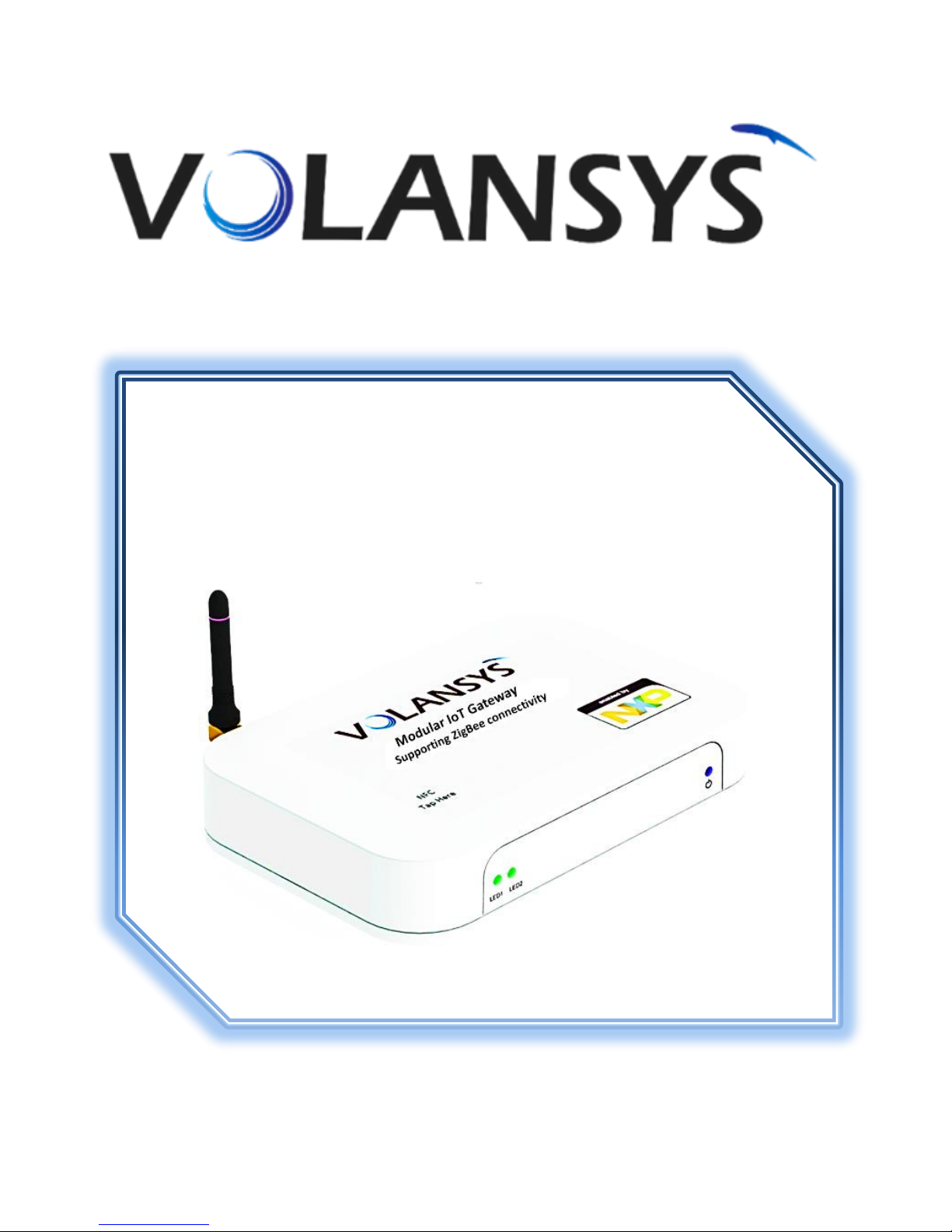
MODULAR IOT GATEWAY
USER MANUAL
THE CUTTING EDGE MODULAR TECHNOLOGY

Modular IoT Gateway User Manual
Copyright Info
The information contained in this document is the proprietary information of Volansys Technologies Pvt.,
Ltd. The contents are confidential and any disclosure to persons other than the officers, employees,
agents or subcontractors of the owner or licensee of this document, without the prior written consent of
Volansys, is strictly prohibited.
Further, no portion of this document may be reproduced, stored in a retrieval system, or transmitted in
any form or by any means, electronic or mechanical, including photocopying and recording, without the
prior written consent of Volansys, the copyright holder.
Volansys publishes this document without making any warranty as to the content contained herein.
Further Volansys reserves the right to make modifications, additions and deletions to this document due
to typographical errors, inaccurate information, or improvements to reference design platforms or
products mentioned in the document at any time and without notice. Such changes will, nevertheless be
incorporated into new editions of this document.
Warranty
For details on the Volansys Modular IoT Gateway warranty policy, please visit our website:
www.volansys.com
Rev0.3 Confidential Copyright © 2016 Volansys
May 24, 2017 Volansys Technologies Page | 2

Modular IoT Gateway User Manual
TABLE OF CONTENTS
1 REVISION HISTORY ........................................................................................................................................ 7
1.1 REVISION HISTORY ............................................................................................................................................ 7
1.2 REFERENCES ..................................................................................................................................................... 7
2 USING THIS MANUAL .................................................................................................................................... 9
2.1 PURPOSE AND AUDIENCE .................................................................................................................................... 9
2.2 SUMMARY OF CHAPTERS ..................................................................................................................................... 9
3 OVERVIEW ................................................................................................................................................... 10
3.1 KEY FEATURES ................................................................................................................................................ 11
3.2 USER CASES ................................................................................................................................................... 12
3.3 PROTOCOL SUPPORT ........................................................................................................................................ 12
3.4 ADDRESSES AND PORT NUMBERS ....................................................................................................................... 12
3.4.1 Hardware Address ................................................................................................................................. 12
3.4.2 IP Address .............................................................................................................................................. 13
3.4.3 Port Numbers ......................................................................................................................................... 13
3.5 REFERENCE DESIGN PLATFORM INFORMATION LABEL .............................................................................................. 13
4 REFERENCE DESIGN PLATFORM ARCHITECTURE AND INTERFACES .............................................................. 14
4.1 MEMORY, I/O PORTS AND EXTERNAL PERIPHERAL SUPPORT .................................................................................... 15
4.1.1 DDR3 ...................................................................................................................................................... 15
4.1.2 NAND Flash ............................................................................................................................................ 15
4.1.3 Micro SD Card Slot ................................................................................................................................. 15
4.2 ETHERNET PORT ............................................................................................................................................. 15
4.3 USB PORTS ................................................................................................................................................... 15
4.4 USB DEBUG PORT .......................................................................................................................................... 16
4.5 WI-FI AND BLUETOOTH .................................................................................................................................... 16
4.6 USER INTERFACE SWITCH .................................................................................................................................. 16
4.6.1 Commissioning Switch (SW1) ................................................................................................................. 16
4.6.2 Reset Switch ........................................................................................................................................... 17
4.7 USER LED INDICATIONS ................................................................................................................................... 17
4.8 NFC CONTROLLER ........................................................................................................................................... 17
4.9 MIKROBUS COMPATIBLE HEADERS ..................................................................................................................... 17
4.10 JN5179 ZIGBEE MODULE ................................................................................................................................ 18
5 INSTALLATION OF GATEWAY ....................................................................................................................... 19
5.1 MODULAR IOT GATEWAY BOX CONTENT ............................................................................................................. 19
5.2 DEVICES INSIDE MODULAR IOT GATEWAY ............................................................................................................ 19
5.3 USER REQUIRED ITEMS ..................................................................................................................................... 19
6 DEMO SETUP OF MODULAR IOT GATEWAY ................................................................................................. 20
7 CONTACT US AND SUPPORT ........................................................................................................................ 21
8 APPENDIX-A ................................................................................................................................................ 22
Rev0.3 Confidential Copyright © 2016 Volansys
May 24, 2017 Volansys Technologies Page | 3

Modular IoT Gateway User Manual
8.1 ACRONYMS & GLOSSARY .................................................................................................................................. 22
9 APPENDIX-B ................................................................................................................................................ 23
9.1 COMPLIANCE .................................................................................................................................................. 23
9.2 ROHS, REACH COMPLIANCE ............................................................................................................................ 23
Rev0.3 Confidential Copyright © 2016 Volansys
May 24, 2017 Volansys Technologies Page | 4

Modular IoT Gateway User Manual
List of Figures
Figure 1 – Modular IoT Gateway ....................................................................................................... 10
Figure 2 - Modular IoT Gateway With Inbuilt Peripheral .................................................................... 10
Figure 3 – Modular IoT Gateway With Inbuilt Peripheral ................................................................... 12
Figure 4 – Reference Design platform information Label ................................................................... 13
Figure 5 – Architecture Block Diagram .............................................................................................. 14
Figure 6 – Inside view of Modular IoT Gateway ................................................................................. 14
Figure 7 – Reference design Platform interface details ...................................................................... 15
Figure 8 – Modular IoT Gateway Switches ......................................................................................... 16
Figure 9 - NFC Controller .................................................................................................................. 17
Figure 10 - MikroBUS Header............................................................................................................ 18
Figure 11 - JN5179 Module ............................................................................................................... 18
Rev0.3 Confidential Copyright © 2016 Volansys
May 24, 2017 Volansys Technologies Page | 5

Modular IoT Gateway User Manual
List of Tables
Table 1 - Revision History ...................................................................................................................7
Table 2 – References ..........................................................................................................................7
Table 3 - References ...........................................................................................................................9
Table 4 - Gateway USB Configuration ............................................................................................... 15
Table 5 - Terminal Settings ............................................................................................................... 16
Table 6 - User Interface Switch ......................................................................................................... 17
Table 7 - User LED Indications ........................................................................................................... 17
Table 8 – Modular IoT Gateway Reference design platform Content .................................................. 19
Table 9 - Modular IoT Gateway Unit Contents ................................................................................... 19
Table 10 – Other Require Equipment ................................................................................................ 19
Table 11 - Acronyms & Glossary ....................................................................................................... 22
Rev0.3 Confidential Copyright © 2016 Volansys
May 24, 2017 Volansys Technologies Page | 6
Modular IoT Gateway User Manual
Rev.
Date
Description
Prepared By
Reviewed By
Approved By
0.1
21-Nov-16
Initial draft version
released
Volansys
Volansys
0.2
02-March-17
Updated based on review
comments
Volansys
Volansys
0.3
03-March-17
Updated based on review
comments
Volansys
Volansys
0.4
01-May-17
Added RF statement
Volansys
Volansys
0.5
24-May-17
Remove watermark
Added FCC RF statement
Volansys
Volansys
Documents
Revision
i.MX6UL Base Board Hardware User Guide
0.1
Datasheet of JN5179 Module
1.1
Quick start Guide of PN7120 NFC Controller Board
1.1
1 REVISION HISTORY
1.1 Revision History
Table 1 - Revision History
1.2 References
Table 2 – References
Rev0.3 Confidential Copyright © 2016 Volansys
May 24, 2017 Volansys Technologies Page | 7

Modular IoT Gateway User Manual
Rev0.3 Confidential Copyright © 2016 Volansys
May 24, 2017 Volansys Technologies Page | 8

Modular IoT Gateway User Manual
Chapter No.
Chapter
Description
3
Overview
Describes Introduction and key features and the protocols it
supports. Includes technical specifications.
4
Reference Design
Architecture and
Interfaces
Describes Hardware interface idea and wireless technology
support details.
5
Installation of Gateway
Describe details of List of content in box of Reference design
platform and how to install it on field
6
Demo Setup of
Modular IoT Gateway
Describes setup and configuration procedure with Wi-Fi and
Ethernet using mobile application.
7
Contact us and
support
Instructions for contacting Volansys and Technical Support
details
8
Appendix A
Acronyms and Glossary – Full forms of used short names
9
Appendix B
Gateway compliance details
2 USING THIS MANUAL
2.1 Purpose and Audience
This document provides Introduction, key features, Reference design platform Architecture and
interfaces, demo setup and use of Modular IoT Gateway. It is intended for the users who are configuring
this Reference design platform. The user need to use this reference design platform in well controlled
indoor environment.
2.2 Summary of chapters
Table 3 - References
Rev0.3 Confidential Copyright © 2016 Volansys
May 24, 2017 Volansys Technologies Page | 9

Modular IoT Gateway User Manual
3 OVERVIEW
Modular IoT Gateway is a smart, modular, customizable, multi-service advance Reference Design
Platform for Internet of Things. It is targeted for multiple use cases in various segments of IoT such as
Smart Home, Buildings and Industries. Powered by industrial leading technologies, the Gateway is
designed with Core features like Modular Hardware Design and Multi-Radio Connectivity
NFC and ZigBee)
.
(i.e. Wi-Fi, BLE,
Figure 1 – Modular IoT Gateway
The Modular IoT Gateway, based on advance processor i.MX6UltraLite introduces users to the assembled
version of Gateway carrier and SoM board inside the platform. This gateway will help users to develop
and run their IoT based concept using wireless interfaces like Wi-Fi, BLE, NFC and ZigBee easily and operate
any supported devices wirelessly. It supports Wi-Fi and Ethernet for communication with cloud.
The Modular IoT Gateway supports various versatile wireless hardware module through MikroBUS Header
such as Volansys’ RF Modules and other MikroBUS standard supported modules. It also support new
generation features PN7120 base NFC module and NXP JN5179 ZigBee Module.
Figure 2 - Modular IoT Gateway With Inbuilt Peripheral
Rev0.3 Confidential Copyright © 2016 Volansys
May 24, 2017 Volansys Technologies Page | 10

Modular IoT Gateway User Manual
3.1 Key Features
The following specifications are available in the Modular IoT Gateway Reference design platform:
Power Supply
o DC Jack for Input - 5V/3A from adaptor
Processor
o i.MX 6UltraLite applications processor with a 528 MHz ARM® Cortex®-A7 core
Memory
o 256MB DDR3L SDRAM
o 1GB NAND Flash
o Micro SD connector
Ethernet
o 1x 10/100Mbps Ethernet RJ-45 connector
USB Port
o 1x USB 2.0 Host connector
o 1x USB 2.0 Host connector (Device mode support)
Wireless Technology
o Wi-Fi 802.11b/g/n and 802.15.1 BLEv4.0 compatible Wi-Fi + BT module from Murata
o 802.15.4/ZigBee Module JN5179
o NFC module using PN7120 controller for commissioning
Header Support
o MikroBus opatile header to support ikroBU“ opatile Volass’ RF modules & all
other MikroBU“’ lik odules hih is uiersall aepted ith sae header opatiilit
Other I/O
o 1x Debug port via USB micro-B connector
o 1x Power LED, 2x Status LED
o 1x User Switch (for commissioning), 1x reset Switch
o JTAG connector
Dimension
o 146.045 mm x 96.656 mm x 27.537 mm
Weight
o 250 Grams
Operating Temperature and Humidity
o 0 to 50 °C, 10% to 80% RH (Non-considering)
Storage Temperature and Humidity
o -10 to 50 °C, 5% to 80% RH (Non-considering)
Rev0.3 Confidential Copyright © 2016 Volansys
May 24, 2017 Volansys Technologies Page | 11

Modular IoT Gateway User Manual
3.2 User Cases
Figure 3 – Modular IoT Gateway With Inbuilt Peripheral
Volansys modular IoT gateway is central device to test gateway out of box. In this demo, user can
control and monitor ZigBee end devices with help of mobile application. In order to use, Modular IoT
Gateway, user needs to provide Internet connectivity to gateway board. The Gateway board support
Ethernet and Wi-Fi interface for cloud connectivity. Gateway also support NFC commission. Using this NFC
commission method user can provide Wi-Fi credential to Gateway and register them. User seamless add
ZigBee deie i Gatea etork NFC oissio ethod. Oe Ed deies are added to Gatea’s
network then user can control them remotely. Here note that the user need to use this reference design
platform in well controlled indoor environment.
3.3 Protocol Support
The Modular IoT Gateway contains a full-featured IP networking and wireless software stack:
DHCP Client, DHCP Server, DHCPv6 Client
uPnP (Discovery), LCAP (77FE), SSH, SSLv3/TLSv1, HTTP(S)
IPv4/IPv6, TCP, UDP, ICMP, ARP, Auto-IP, DNS
WPA/WPA2 Personal
3.4 Addresses and Port Numbers
3.4.1 Hardware Address
The hardware address is also referred to as the Ethernet address, physical address, or MAC address. The
first three bytes of the Ethernet address are fixed and identify the unit as a volansys reference design
platform. The fourth, fifth, and sixth bytes are unique numbers assigned to each unit. Sample ways
hardware address may be represented:
00-80-A3-14-1B-18
00:80:A3:14:1B:18
Rev0.3 Confidential Copyright © 2016 Volansys
May 24, 2017 Volansys Technologies Page | 12
Modular IoT Gateway User Manual
3.4.2 IP Address
Every device connected to an IP network must have a unique IPv4 address. This address references the
specific unit.
3.4.3 Port Numbers
Every TCP connection is defined by a destination and source IP Address, and a destination and source
port number. For example, a Telnet server commonly uses TCP port number 23.
The following is a list of the default server port numbers running on the Modular IoT Gateway:
TCP Port 22: SSH Server (Command Mode configuration)
TCP Port 80: HTTP (Web Manager Configuration)
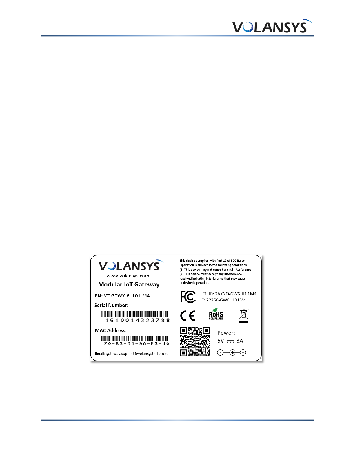
3.5 Reference design platform information Label
The Reference design platform information label on the device contains the following information about
the specific unit:
Company Logo
Model Name
Platform Part Number
Serial Number and Barcode
MAC Address and Barcode
Power Rating
FCC and CE certificate details
e.g.:
Figure 4 – Reference Design platform information Label
Rev0.3 Confidential Copyright © 2016 Volansys
May 24, 2017 Volansys Technologies Page | 13

Modular IoT Gateway User Manual
4 REFERENCE DESIGN PLATFORM ARCHITECTURE AND INTERFACES
Modular IoT
Module.
The architecture block diagram of Modular IoT Gateway board is shown as below:
Gateway implements a variety of peripheral interfaces to connect with i.MX6UL based SoM
This section provides detailed information about different peripherals of Modular IoT Gateway.
Figure 5 – Architecture Block Diagram
The inside view of Modular IoT Gateway is shown in following figures,
Figure 6 – Inside view of Modular IoT Gateway
Rev0.3 Confidential Copyright © 2016 Volansys
May 24, 2017 Volansys Technologies Page | 14

Modular IoT Gateway User Manual
USB-2 HOST
USB-2 DEVICE
JUMPER 1 (J30)
CLOSE
OPEN
JUMPER 2 (J29)
OPEN
CLOSE
4.1 Memory, I/O Ports and external peripheral support
4.1.1 DDR3
Modular IoT Gateway is equipped with 256 MB DDR3L Memory which is upgradable up to 1 GB.
4.1.2 NAND Flash
Gateway is available with on-board NAND (1GB) flash.
4.1.3 Micro SD Card Slot
Micro SD slot (J18) is provided on Modular IoT Gateway.
It is connected to USDHC1 interface of i.MX 6UltraLite on SoM Module.
Figure 7 – Reference design Platform interface details
4.2 Ethernet Port
Modular IoT Gateway incorporates a single full-featured 10/100 Ethernet interface, implemented with
the i.MX6UL MAC-NET core in conjunction with a 10/100-Mbit/s MAC coupled with an on-board 10/100
PHY.
The modular IoT Gateway comes with following features:
Integrated PHY on SoM for 10/100 Mbps
Auto-negotiation support
Programmable MAC address
4.3 USB Ports
The USB interface block provides two High speed USB port, which supports USB ver. 2.0. Initially both the
connectors will act as host. User can configure USB-2(J17) port as device also by modifying jumpers
setting. USB-1 (J16) will work as host only.
Jumper setting for USB-2 port host and device mode are shown in below table:
Table 4 - Gateway USB Configuration
Rev0.3 Confidential Copyright © 2016 Volansys
May 24, 2017 Volansys Technologies Page | 15

Modular IoT Gateway User Manual
Baud Rate
115200
Data Bits
8
Parity
None
Stop Bits
1
Flow Control
None
When using serial download option for Boot, USB-2(J17) will be used in Device mode. It is required to
change Jumper setting to enable device mode.
4.4 USB Debug Port
The Modular IoT Gateway comes with one microUSB debug port support to simplify debugging
mechanism. A CP2102, USB to serial UART IC is used to convert the UART signals to USB. A micro-B to
standard A USB cable can be used. UART1 port is used as the debug port.
The required terminal settings are shown in the following table:
Table 5 - Terminal Settings
4.5 Wi-Fi and Bluetooth
Modular IoT Gateway provides support of Single Band (2.4GHz) Wi-Fi and Bluetooth using Murata’s
LBEE5KLDX RF module on Gateway.
The Modular IoT Gateway supports following features:
Support of single band IEEE 802.11b/g/n Wi-Fi
Bluetooth ver. 4.1
Provides SDIO interface for Wi-Fi and UART interface for Bluetooth operation
External u.fl connectors is connected with antenna line of module to provide external Whip
antenna support
4.6 User Interface Switch
4.6.1 Commissioning Switch (SW1)
SW1 is used to start/stop NFC commissioning mode. It is also used to power off the gateway board by
long pressing it for more than 15 sec.
Rev0.3 Confidential Copyright © 2016 Volansys
May 24, 2017 Volansys Technologies Page | 16
Figure 8 – Modular IoT Gateway Switches

Modular IoT Gateway User Manual
Switch
Control
Last State
Next State
SW1
Short Press
( >5sec &
< 15sec)
NFC Commission Window Off
Start NFC commission window
NFC Commission Window ON
Stop NFC commission window
Long press
(> 15sec)
Any
Power off gateway board
LED
Behavior
Represents
LED1
Green
Connected to cloud
Red
Not Connected to cloud
Orange
Connecting to cloud
LED2
Green
Commission window is On
Orange
Commission window is Off
Blink fast for 10 times
ED Commission successful
Blink slow for 5 times
ED Commission failed
Different control mechanism for switch is provided as below:
Table 6 - User Interface Switch
4.6.2 Reset Switch
One reset switch is provided for user, to reboot the system without removing power supply. Pressing the
switch will drive logic zero on RESETn signal, which will affects every modules on gateway.
4.7 User LED Indications
Two dual color LEDs are used to provide indication about different Gateway functionalities. Below table
indicates color mark to represent specific events.
Table 7 - User LED Indications
Note: User can change LEDs behavior based on their use case scenario.
4.8 NFC Controller
Modular IoT gatea hae NFC Module Header for NFC Coetiit. It’s hae PN7 NFC Cotroller
from NXP Semiconductor.
Figure 9 - NFC Controller
4.9 MikroBus Compatible Headers
Modular IoT Gateway contains two standard MikroBUS header which provides SPI, I2C & UART interface
and other MikroBUS standard support signals. MikroBUS standard click board can be used with Modular
Rev0.3 Confidential Copyright © 2016 Volansys
May 24, 2017 Volansys Technologies Page | 17

Modular IoT Gateway User Manual
2.4GHz IEEE802.15.4 compliant
IoT Gateway board. Below figure displays Standard MikroBUS socket position on Modular IoT Gateway
board:
Figure 10 - MikroBUS Header
4.10 JN5179 ZigBee Module
NXP’s ZigBee odule hae JN5179 wireless controller which was low power supporting for ZigBee
interface.
JN5179 module supports following features:
512KB Flash
32KB RAM
uFl PCB antenna or Internal Antenna or Both support
Compact size: 14.5mm x 20.5mm
TX power 8.5 dBm
Receiver sensitivity –96 dBm
TX current 24 mA at 10 dBm
TX current 21.2 mA at 8.5 dBm
RX current 14.3 mA at maximum input level –2 dBm
2.0 V/3.6 V operation
Rev0.3 Confidential Copyright © 2016 Volansys
May 24, 2017 Volansys Technologies Page | 18
Figure 11 - JN5179 Module

Modular IoT Gateway User Manual
Item
Description
Modular IoT
Gateway Unit
Comes with External Antenna
attached
Power Adapter
DC 5V, 3A – plug in with Gateway to
power up Gateway
Documentation
Quick Start Guide
Item
Description
SoM
Based on i.MX6UL processor, 200-pin
SO-DIMM standard supported
module
Base Board
Multiple RF interface support with
Volass’ “oM
NFC Module
For commissioning of different
modules
JN5179 module
Provides ZigBee interface support
Item
Description
USB Cable
USB Cable (micro B to standard A)
Ethernet Cable
To connect with network using Ethernet
Micro SD Card
Bootable Linux image
NFC Tags
To register/commission on network through Gateway
Internet connectivity
To connect Gateway via Ethernet or Wi-Fi
Mobile Application
To operate Gateway
Windows PC
To update firmware and get EUI-64 of FRDM-KW24D512
5 INSTALLATION OF GATEWAY
The Modular IoT Gateway comes with its required contents and it is mentioned in below section.
5.1 Modular IoT Gateway Box Content
Modular IoT Gateway comes with following listed items:
Table 8 – Modular IoT Gateway Reference design platform Content
5.2 Devices inside Modular IoT Gateway
Modular IoT Gateway has different peripherals support. It contains following peripherals to support
different functionality and all must be installed inside Gateway:
Table 9 - Modular IoT Gateway Unit Contents
5.3 User required Items
To complete your demo installation you need following items and it is not standard parts of Modular IoT
Gateway. User needs to manage it.
Table 10 – Other Require Equipment
Note: Recommended Ethernet cable length is 3mm or less.
Rev0.3 Confidential Copyright © 2016 Volansys
May 24, 2017 Volansys Technologies Page | 19

Modular IoT Gateway User Manual
6 DEMO SETUP OF MODULAR IOT GATEWAY
Kindly refer Modular IoT Gateway OOB Demo Setup Guide-v1.1 for Demo setup and configuration.
Rev0.3 Confidential Copyright © 2016 Volansys
May 24, 2017 Volansys Technologies Page | 20

Modular IoT Gateway User Manual
7 CONTACT US AND SUPPORT
INDIA Office: USA Office:
Block A - 7th Floor, 3080 Olcott St. Suite D235
Safal Profitaire, Santa Clara CA – 95054.
Corporate Road, Phone: +1 510 358 4310
Prahaladnagar,
Ahmedabad, Gujarat 380015
Phone: + 91-79-40041994.
E-mail:
Volansys offers many resources to support our customers and reference design platforms at
Website:
For instance, you can ask a question and other technical details related to reference design platforms at
our website. At this site you can also find FAQs, bulletins, warranty information, extended support services
and Reference design platform documentation.
www.volansys.com
sales@volansys.com
To contact technical support or sales, look up your local office at:
When you report a problem, please provide the Following information:
Your name, company name, address, and phone number
Description of the problem
Status of the unit when the problem occurred.
http://volansys.com/contact/
Rev0.3 Confidential Copyright © 2016 Volansys
May 24, 2017 Volansys Technologies Page | 21
Modular IoT Gateway User Manual
Sr No#
Terms
Definition
1.
BLE/BT
Bluetooth Low Energy/Bluetooth
2.
eMMC
Embedded Multimedia Card
3.
GPIO
General Purpose Input and Output
4.
GPS
Global Positioning System
5.
GSM
Global System for Mobile Communication
6.
I2C
Inter Integrated Circuit
7.
IoT
Internet Of Things
8.
JTAG
Joint Test Action Group
9.
LDO
Low Dropout
10.
LED
Light Emitting Diode
11.
MCU
Microcontroller Unit
12.
NFC
Near Field Communication
13.
PMIC
Power Management Integrated Circuits
14.
SDRAM
Synchronous Dynamic Random Access Memory
15.
SMA
Subminiature version A
16.
SoC
System on Chip
17.
SoM
Systems On Module
18.
SPI
Serial Peripheral Interface
19.
TBD
To Be Define
20.
U.FL
Ultra-Miniature RF Connector
21.
UART
Universal Asynchronous receiver and Transmitter
22.
USB
Universal Serial Bus
8 APPENDIX-A
8.1 Acronyms & Glossary
The following terms are used in this document
Rev0.3 Confidential Copyright © 2016 Volansys
May 24, 2017 Volansys Technologies Page | 22
Table 11 - Acronyms & Glossary

Modular IoT Gateway User Manual
9 APPENDIX-B
9.1 Compliance
(According to ISO/IEC Guide and EN 45014)
Reference Design Platform Name Model:
Modular IoT Gateway
Conforms to the following standards or other normative documents:
Safety
EN 60950-1:2006 + A11:2009 + A1:2010 + A12:2011 + A2:2013
Emissions
CFR Title 47 FCC Part 15, Subpart B, Class A Emissions
EN55022: 2010, Class A Emissions
CISPR 22: 2009, Class A Emissions
Immunity
EN55024: 2010
EN610000-4-2: 2009
EN61000-4-3: 2006 + A1: 2008 + A2: 2010
EN61000-4-4: 2004
EN61000-4-5: 2005
EN61000-4-6: 2009
EN61000-4-8: 2010
EN61000-4-11: 2004
CISPR 16-1-4: 2008
ICES-0003 Issue 6
9.2 RoHS, REACH Compliance
Rev0.3 Confidential Copyright © 2016 Volansys
May 24, 2017 Volansys Technologies Page | 23

Modular IoT Gateway User Manual
FCC Statement
This equipment has been tested and found to comply with the limits for a Class B digital device, pursuan
t to part 15 of FCC Rules. These limits are designed to provide reasonable protection against harmful int
erference in a residential installation. This equipment generates and can radiate radio frequency energy
and, if not installed and used in accordance with the instructions, may cause harmful interference to rad
io communications. However, there is no guarantee that interference will not occur in a particular install
ation. If this equipment does cause harmful interference to radio or television reception, which can be d
etermined by turning the equipment off and on, the user is encouraged to try to correct the interference
by one or more of the following measures:
Reorient or relocate the receiving antenna.
Increase the separation between the equipment and receiver.
Connect the equipment into an outlet on a circuit different from that to which the receiver is connected.
Consult the dealer or an experienced radio/TV technician for help.
This device complies with Part 15 of FCC Rules. Operation is subject to the following two conditions: (1)
This device may not cause harmful interference, and (2) This device must accept any interference receiv
ed, including interference that may cause undesired operation.
Note: The manufacturer is not responsible for any radio or TV interference caused by unauthorized modi
fications to this equipment. Such modifications could void the user’s authority to operate this equipmen
t.
IC Compliance
This device complies with Industry Canada license ‐
exempt RSS standard(s). Operation is subject to the following two conditions: (1) this device may not cau
se interference, and (2) this device must accept any interference, including interference that may cause
undesired operation of the device.
Le present appareil est conforme aux CNR d’Idustrie Canada applicables aux appareils radio exempts d
e licence. L’eploitatio est autorisée aux deux conditions suivantes: (1) l’appareil ne doit pas produire d
e brouillage, et (2) l’utilisateur de l’appareil doit accepter tout brouillage radioélectrique subi, même si l
e brouillage est susceptible d’e compromettre le fonctionnement.
RF Radiation Exposure Statement
This equipment complies with FCC RF radiation exposure limits set forth for an uncontrolled environment.
This equipment should be installed and operated with a minimum distance of 20 centimeters between
the radiator and your body.
The device has been evaluated to meet FCC and RSS-102 general RF exposure requirement.
Rev0.3 Confidential Copyright © 2016 Volansys
May 24, 2017 Volansys Technologies Page | 24
 Loading...