

Page 1

VoSS12
Admin Guide
2012-07
VoLANs Co., Ltd.
Page 2

ⓒ
2010 VoLANs Co., Ltd. All Rights Reserved.
The information contained in this document is subject to change without notice and
does not represent a commitment on the part of VoLANs Co., Ltd. The information
in this document is believed to be accurate and reliable, however, VoLANs Co., Ltd.
assumes no responsibility or liability for any errors or inaccuracies that may appear in
the document.
Complying with all applicable copyright laws is the responsibility of the user. No part
of this document may be reproduced, stored in or introduced into a retrieval system, or
transmitted in any form or by any means (electronic, mechanical, photocopying,
recording, or otherwise), or for any purpose, without the express written permission of
VoLANs Co., Ltd.
VL1100, VL1025, VL1020, VOSS12 are trademarks of VoLANs Co., Ltd.
The names of actual companies and products referred to in this document may be the
trademarks of their respective owners.
Page 3

Table of Contents
Table of Contents
1. System Structure and Set-up ........................................................................................................................... 3
System Structure ............................................................................................................................................. 3
Installation ...................................................................................................................................................... 8
2. Service Structure and User Manage ment ..................................................................................................... 13
Service Structure ........................................................................................................................................... 13
Structure of SIP Service ................................................................................................................................ 14
3. Web Manager .................................................................................................................................................. 15
Set-up PC’s IP Address ................................................................................................................................. 15
Login Web Manager ..................................................................................................................................... 16
Web Manager Menu Tree ............................................................................................................................. 17
4. Status ............................................................................................................................................................... 19
[Status]/[System] .......................................................................................................................................... 19
[Status]/[Network] ........................................................................................................................................ 21
[Status]/[Event] ............................................................................................................................................. 22
[Status]/[Active Phone] ................................................................................................................................ 23
[Status]/[Statistics] ........................................................................................................................................ 23
[Status]/[Monitor] ......................................................................................................................................... 24
5. Call Log ........................................................................................................................................................... 27
[Call Log]/[Current]...................................................................................................................................... 27
[Call Log]/[Log] ........................................................................................................................................... 28
[Call Log]/[Call Length Per Day] ................................................................................................................. 29
[Call Log]/[Call Length Per No.] .................................................................................................................. 29
[Call Log]/[CDR] ......................................................................................................................................... 30
[Call Log]/[CDR Config] ............................................................................................................................. 31
[Call Log]/[Record] ...................................................................................................................................... 32
6. Basic ................................................................................................................................................................. 34
[Basic]/[Profile] ............................................................................................................................................ 34
[Basic]/[User] ............................................................................................................................................... 37
[Basic]/[Group] ............................................................................................................................................. 43
[Basic]/[Line] ................................................................................................................................................ 55
[Basic]/[VSP] ................................................................................................................................................ 59
[Basic]/[Dialplan] ......................................................................................................................................... 63
[Basic]/[Feature Code] .................................................................................................................................. 66
[Basic]/[Organization] .................................................................................................................................. 71
7. Advanced ......................................................................................................................................................... 72
[Advanced]/[SIP] .......................................................................................................................................... 72
[Advanced]/[PBX] ........................................................................................................................................ 73
[Advanced]/[Mail] ........................................................................................................................................ 75
[Advanced]/[Conference] ............................................................................................................................. 76
[Advanced]/[IVR] ......................................................................................................................................... 79
[Advanced]/[RAA] ....................................................................................................................................... 82
AdminGuide-Voss12-1.docx 1
Page 4

Table of Contents
[Advanced]/[Incoming Dialplan] .................................................................................................................. 83
[Advanced]/[Phonebook] .............................................................................................................................. 84
[Advanced]/[Emergency No.] ....................................................................................................................... 86
8. System .............................................................................................................................................................. 88
[System]/[Network] ...................................................................................................................................... 88
[System]/[MOH] ........................................................................................................................................... 90
[System]/[Time] ............................................................................................................................................ 91
[System]/[Admin] ......................................................................................................................................... 92
[System]/[Admin Authority] ......................................................................................................................... 94
[System]/[SNMP] ......................................................................................................................................... 97
[System]/[QoS/Port Fwd.] ............................................................................................................................ 97
[System]/[Monitor] ....................................................................................................................................... 99
[System]/[Record] ...................................................................................................................................... 100
9. Security .......................................................................................................................................................... 102
[Security]/[Security Config.] ...................................................................................................................... 102
[Security]/[ACL] ........................................................................................................................................ 103
10. Maintenance ................................................................................................................................................ 104
[Maintenance]/[Reload] .............................................................................................................................. 104
[Maintenance]/[Reboot] .............................................................................................................................. 105
[Maintenance]/[Factory Default] ................................................................................................................ 105
[Maintenance]/[Backup/Restore] ................................................................................................................ 107
[Maintenance]/[S/W Upgrade] ................................................................................................................... 108
[Maintenance]/[Phone Profile] ................................................................................................................... 109
[Maintenance]/[Phone S/W Manager] ........................................................................................................ 112
A. Safety Instructions ....................................................................................................................................... 1 15
Emergency Case ......................................................................................................................................... 115
General Safety Instruction .......................................................................................................................... 116
B. Perl Regular Expression .............................................................................................................................. 1 19
C. How to Use FXS .............................................................................................................
.............................. 121
Glossary ............................................................................................................................................................. 124
2
AdminGuide-Voss12-1.docx
Page 5
1. System Structure and Set-up
System Structure
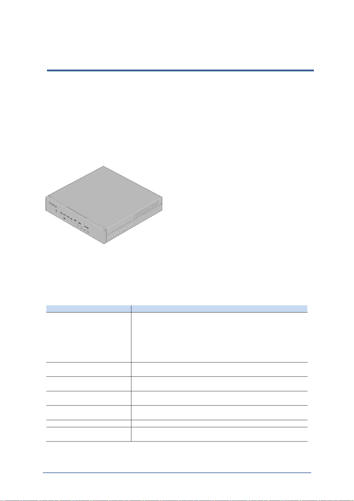
Main System
The front of VOSS12 has status display LEDs, and the rear part has connectors to
connect power adaptor, PSTN line, Ethernet cable.
Figure 1-1. Front View of Voss12
System Specification
The following is VOSS12 system specification.
Table 1-1. System Specification
Category Detail
Hardware Specifications
Network Interfaces
PSTN Interfaces
Other Interfaces
Power Adaptor
Power Consumption Max. Operational Power Consumption: 20 W
Physical
Specifications
Dual Core Network Processor
Main Memory : 1Gbit DDR2–SDRAM * 2
Storage: 512Mbyte Flash Disk
LED Status Indicators
- 2 Bi-color LEDs for Board Status Indication
- 2 Bi-color LEDs for Network Status Indication
- 2 Bi-color LEDs for Each FXO/FXS ports
WAN : 1 P or t s
LAN : 1 Ports
FXO : 2 Ports
FXS : 2 Ports
DC 12V Power connector
Restore Factory Defaults Button Restore Factory Defaults Button
Input : 100 - 240 V~1A 50/60 Hz
Output : 12V/2.5A
Dimensions : 138 (W) x 98 (D) x 32 (H) mm
Weight : 190g (without Power Adaptor)
AdminGuide-Voss12-1.docx 3
Page 6
1. System Structure and Set-up
System Capacity
Ethernet Interface
Specifications
PSTN Interface
Specifications
Environmental
Specifications
Hardware
Max. Extensions: 5
Max. Voice Mail: 60 Minutes per each subscriber
Max Call performance : 1 Call per second(CPS)
CDR Database: up to 20MByte records
IVR: 100 Min.
WAN : 10Base-T, 100Base-TX, complying IEEE 802.3 Standards,
Supports Auto-Negotiation
LAN : 10Base-T, 100Base-TX, complying IEEE 802.3 Standards,
Support Auto-Negotiation
RJ-45 Connector: Ethernet packets over CAT5-UTP cable
2 Pin(Tip-Ring) RJ-11 Connector for each PSTN port
Up to 1KV Line Isolation and Surge Protection
TX power of up to +10 dBm into 600Ohm
Ringing Detection
CID Monitoring and Detection
Parallel phone Detection
Operating Temperature: 0ºC ~ 50ºC
Operating Humidity: 20% ~ 80% RH
Storage Temperature: -20ºC ~ 60ºC
Storage Humidity: 20% ~ 95% RH
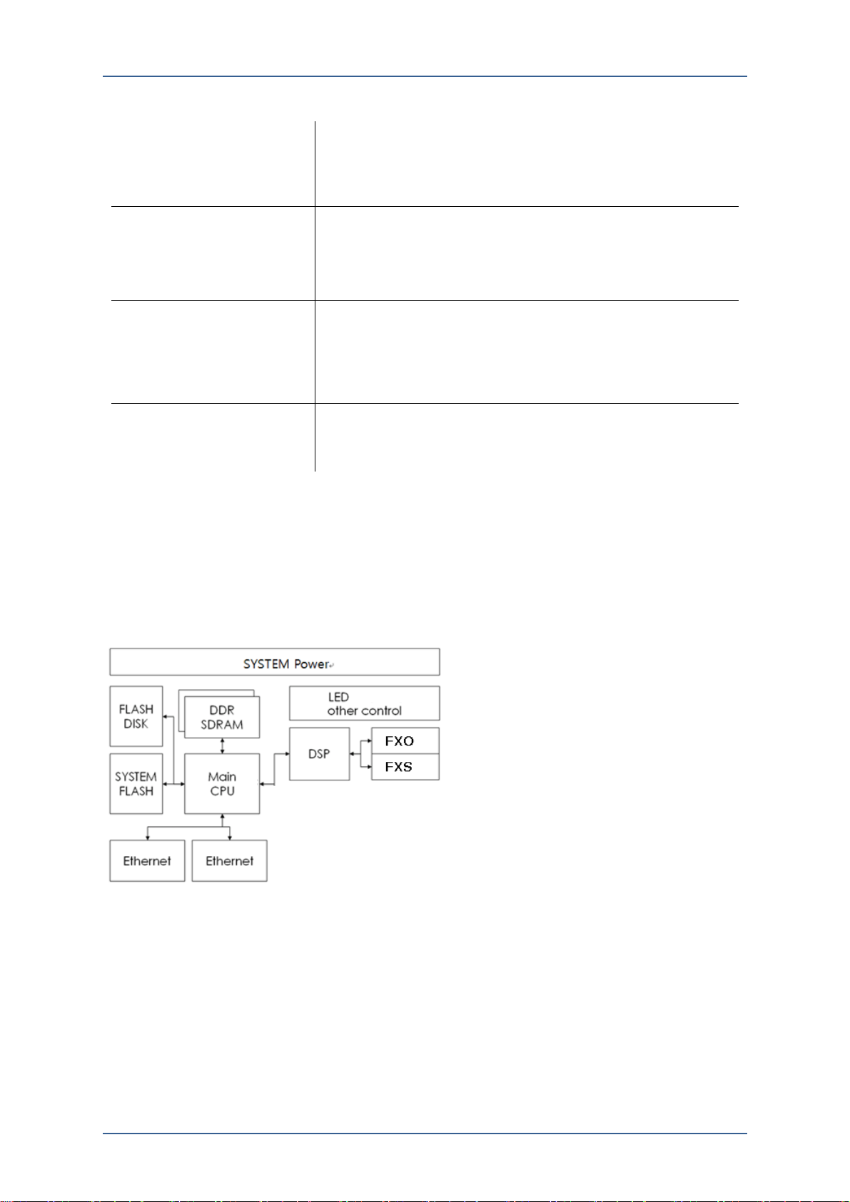
VOSS12 is composed with optimized Hardware for SOHO which has less than 5
employees.
Figure 1-3. VOSS12 Block Diagram
Status LED
The following Figure1-4. is the front view of VOSS12 and this shows 7 LED and
one of Reset hole. Each LED shows system operating status and network status
with Green/Red 2 colors.
4
AdminGuide-Voss12-1.docx
Page 7
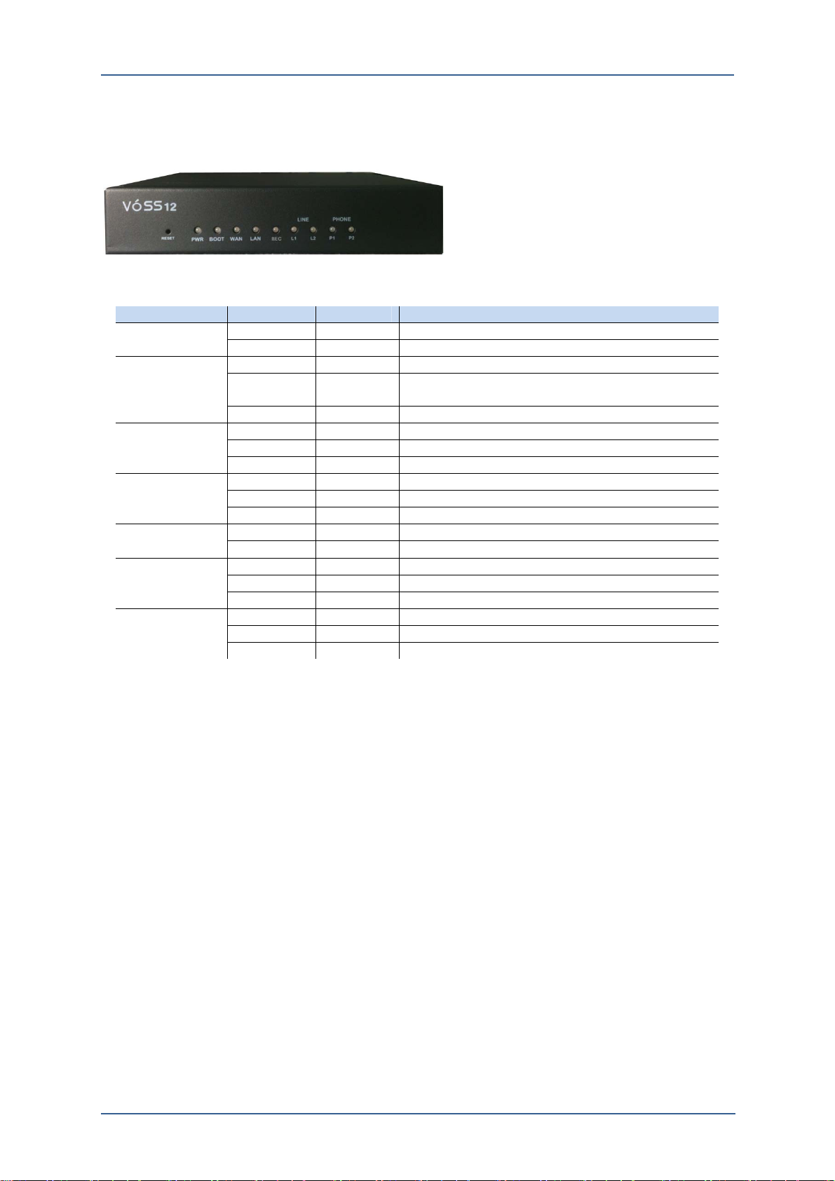
Figure 1-4. Front View of VOSS12
Table 1-2. LED Status Indication
LED Green Red Description
Power ON OFF Power Supply in good condition
OFF OFF Powered Off
Boot ON OFF On Booting
ON ON Will be turn off within 60Sec
Turning to Factory Default
Blinking OFF Normal Operation
WAN ON OFF Link up
Blinking OFF On Packet Communication
OFF OFF Link down
LAN ON OFF Link up
Blinking OFF On Packet Communication
OFF OFF Link down
USB ON OFF USB Mounting
Blinking Off Voice Recording
FXO ON OFF TEL Line is connected
OFF ON TEL Line is busy
OFF Blinking TEL Line is ringing
FXS ON OFF FXS port is held(Hold)
OFF ON FXS port is on the line(Busy)
OFF Blinking Ringing
1. System Structure and Set-up
Factory Default
The small hole in the Left down on Figure 1-4. is the Factory default button which
is connected to a button inside the system. If the system lost IP address, you will
not be able to access the system. In that case, this button will return the system to
factory default status.
With a clip or the edge of pen press the button for 5 seconds then the system will
return to factory default. Once factory default is started, PWR LED turns on red
color and after completed factory default the RWR LED turns on green color and
reboots the system. Therefore, press the reset button until the PWR LED turns on
red color. The factory default IP address of VOSS12 is ‘192.168.1.10’. To connect
the system with your computer, connect a network cable to LAN port.
Line and Frame Earth Connection
The following Figure 1-1 shows the rear view of VOSS12 which is composed with
2 RJ-25 ports, 1 FXO ports, and 1 Life Line. The ‚ⓐ‛ indicates Frame
Ground(F.G) which protects users and the product from surge, lightening, and
electric shock. Therefore, the FE should be connected for safety purpose
AdminGuide-Voss12-1.docx 5
Page 8

1. System Structure and Set-up
-
System Feature
The following table shows all the features of VOSS12.
Table 1-3. System Feature
Category Detail
Standards
Basic PBX Features
IPv4/v6 Dual Stack
VoIP
- DNS
DNS Basic (RFC 1034/1035)
UPDATE (RFC 2136)
SRV (RFC 2782)
NAPTR (RFC 2915)
- SIP
SIP Basic (RFC 3261)
Reliability of Provisional Responses (RFC 3262)
An Offer/Answer Model with SDP (RFC 3264)
Event Notification (RFC 3265)
Asserted Identity within Trusted Networks (RFC 3325)
Instant Messaging (RFC 3428)
Message Waiting Indication (RFC 3842)
Presence (RFC 3856)
Session Timers (RFC 4028)
INFO Method (RFC 2976)
- SDP
SDP (RFC 2327)
- RTP
RTP/RTCP (RFC1889)
RTP AVP (RFC1890)
RTP Payload for DTMF Digits (RFC 2833)
etc
- DHCP
- FTP
- HTTP/HTTPS
- NAT
- NFS
- NTP
- SMTP
- SNMPv2
TFTP
Call Hold/Unhold
Call Transfer (Blind/Attended)
Call Forwarding (Always/Busy/No-Answer/Error/Time-Based)
Call Pickup (Direct/Group)
Call Park/Unpark
Intercom (Direct/Group)
Threeway Call
Music on Hold
Music on Ringback
Group Ringing (Hunt/Circular-Hunt/Ring-All/Random)
Distinctive Ringing
DTMF Relay (in-audio/rfc2833/SIP Info)
Flexible Dialplan
SIP Trunking
DID/DOD
FXO backup (in case VSP is unavailable)
6
AdminGuide-Voss12-1.docx
Page 9

-
Advanced PBX Features
Codecs
Security
Call Screening
DND
Virtual Caller ID
Anonymous Caller ID
Phonebook
Voicemail (with e-mail forwarding)
Message Waiting Indication
IVR
Conference
RAA
Feature Code
SIP Messaging & Presence
BLF
PBX-to-PBX interoperability
Voice
- G.711 μ/A-Law
- pass-thru only
G.729 A/B
G.723.1 (5.3 Kbps)
G.726 (32 Kbps)
G.722
Video (pass-thru only)
- H.263
- H.264
MPEG-4 SP/ASP
ACL
DoS Protection
DDoS Protection
1. System Structure and Set-up
AdminGuide-Voss12-1.docx 7
Page 10

1. System Structure and Set-up
Analog Interface
Management
FXO
- LEC (G.168)
- Caller ID Detection
- Call Progress Tone Detection
- DTMF Generation & Detection
- VAD/CNG
- Packet Loss Concealment
- Adaptive Jitter Buffer
- Dynamic Payload Support
- Adjustable Audio Frames per Packet
FXS
- Ringing Signal up to 3 LEN
- Type I/II FSK Caller ID Generation & Detection
- Call Progress Tone Generation
- DTMF Generation & Detection
- VAD/CNG
- Configurable Tip/Ring impedance
- Hook Flash Signaling
System Configuration via WEB Manager
Multi Language Support (Korean/English)
Password Protection
Configuration Backup/Restore thru WEB/FTP
S/W Upgrade from Remote Place
Direct Phone Management thru WEB
Auto Provision
Event Log
Call Log
CDR
SNMPv2
Installation
VOSS12 installation requires basic understanding of IP Network, Telephone Line
and Communication. If you are not familiar with installing network device, contact
installation engineer in sales office.
In this chapter, basic installation instructions and safety instructions are mentioned.
Please read thoroughly and follow the instructions.
Check List Before Installation
■ Location and Operation
Do not carry VOSS12 when the system is powered on. This may cause shaking of
the power connector and phone cables which will affect the system operating.
Do not place VOSS12 near to heating device. VOSS12 naturally emits heat.
Therefore, if VOSS12 is near to any heating device, VOSS12 can’t cool down the
device properly. This overheating may cause serious damage on the device.
Thus, always keep 5 cm space from VOSS12’s to both sides of cooling fan. If this
cooling system is blocked, the system temperature will go up and this will cause
serious damages on the device.
It should not be placed less than 0℃ or greater than 45℃. The system operating
temperature is 0℃ ~ 45℃.
■ Carrying the System
Before carrying VOSS12, make sure the device is powered off and all cables are
8
AdminGuide-Voss12-1.docx
Page 11

1. System Structure and Set-up
unplugged. Then, put the system in a box and carry with care. If the device is
dropped, the internal board will be broken.
■ Setting Password
Keep the password properly. If the passwords have been forgotten, the system
should be set as factory default so most of data will be lost.
■ Miscellaneous
VOSS12 system has FXOs to connect telephone lines. Sometimes, a digital
telephone which is provided by Digital Key Phone or Digital PBX is not able to
connect to the VOSS12. Telephone should not be connected to FXO port directly.
If you can’t distinguish the using phone is analog or digital, then contact the phone
supplier or telephone line provider.
A VOSS12 has Ethernet connector and telephone connector. The Ethernet
connector can be plugged into the telephone connector but telephone connector
can’t be plug in to the Ethernet connector. Therefore, before connecting each
connector, please check which connector you need to connect.
Only authorized engineer can disassemble the product. Do not use the other brand
board on VOSS12.
While the AC adaptor is connected to the system, do not upside down. It may cause
damage on the adaptor plug.
In order to prevent damage on the board, when you need to touch the board, touch
the metal part first, after then hold the board.
Before replacing VOSS12 board, should be powered off. During replacement, if
the system is powered on, it may cause serious damage on the system.
Setting-up Sequence
Follow the instruction below for VOSS12 system setting-up.
Find a location which has enough space to install VOSS12.
Carry VOSS12 to the place and unpack the package.
Compose VOSS12 and start Setting-up.
Connect LAN cable and telephone line
Connect Frame Ground on the rear part of the product.
Check whether the power cable has Frame Ground. If not, connect Frame
Ground.
Then, if the system power is on, VOSS12 front power LED will be on and the
system will initiate.
The followings are cautions for setting-up VOSS12.
■ Location and Space
In this section, location and space for safe operating of VOSS12 system will be
mentioned
■ Location
VOSS12 can be placed on a table or rack. The place should meet the other safety
conditions, such as temperature, humidity, condition, and so on.
■ Safety
Do not place near explore-able gas, flammable material, etc, to avoid starting fire.
Before setting-up VOSS12, check the cable allocation, connection status, power
voltage so on.
If the ground detector is opened, find the cause and solve the problem.
■ Temperature/Humidity
The product should be place in the following condition.
AdminGuide-Voss12-1.docx 9
Page 12
1. System Structure and Set-up
The product should not be exposed to direct sunlight. Place in cooling and clean
place to free from dust.
■ Input/Output Voltage
VOSS12 power is used 12V direct current. Provided AP power adaptor is used for
VOSS12
The socket outlet should be located where is protected from accident.
Choose a plug which is the right specification for VOSS12 only.
VOSS12 input and output voltage is as below.
Clean the wet floor before installing VOSS12.
If the cable is spoiled, be careful handling this cable.
The radius of curvature should be more than 6 times of cable length and there
should not have any overlapped point.
Do not place near high-voltage cable.
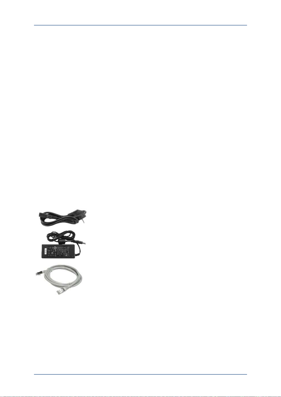
Unpack
After finding a location to set-up VOSS12, then unpack VOSS12 and check the
components as below
Temperature: 0~40℃
Humidity: 10%~90%
Input: AC 100/240V, 50/60Hz
Power Consumption: Max 20Watt
Separately wrapped VOSS12 main device
Power adaptor and ad aptor cable
Ethernet UTP cable(1.5m ): RJ45- CAT 5
Figure 1-6. VOSS12 Package Component
System Assembling
Follow the instruction below to assemble VOSS12.
10
AdminGuide-Voss12-1.docx
Page 13

Cable Connection
1. System Structure and Set-up
■ Ethernet Cable
WAN port is used for composing VoIP network. VOSS12 WAN port provides
Auto-MDIX(Medium-Dependent Interface Crossover) so can apply direct and
cross cable, and can use 10BaseT, 100BaseTX connection. For 10BaseT
connection, use Category-3 cable, and for 100BaseTX connection, use Category-5
cable.
One end of Ethernet cable should be connected to VOSS12 WAN port and the
other end should be connected to Hub or Switch. However, sometimes IP
duplication can be happened in internal network, so connect one end to VOSS12
then refer to the web management chapter for the other end connection.
If the connection doesn’t support 100M connection, please check Hub or Switch
capacity.
■ Telephone Line
VOSS12’s FXO(Foreign eXchange Office) port can use when the port is connected
with PSTN telephone line which is connected to PBX or a Key Telephone System.
One end of cable is connected to FXO port on VOSS12 and the other end is
connected to PBX, Key Telephone System(KTS) or Wall Jack.
For FXO Port cable, use 2 Pin type RJ-11 connector. When making cable, refer to
the table left.
Table 1-4. VOSS12 FXO Port Connection
FXO Port
PIN Name
2 No Connection
3 Tip
4 Ring
5 No Connection
■ FXS Connection
VOSS12 has Life-Line port which can be connect analog telephone. Then, connect
a PSTN line to FXO-#1 port, and connect an analog phone to Life-Line. And off
hook the handset to check whether it plays dial tone even VOSS12 is not powered
on. If the phone doesn’t play dial tone, check whether the phone is connected right
way.
For making the PSTN line cable, refer to the Table 1-5.
Table 1-5. VOSS12 Life-Line/FXS Port Connection
FXS Port
PIN Name
2 No Connection
3 Tip or Ring
4 Ring or Tip
5 No Connection
AdminGuide-Voss12-1.docx 11
Page 14

1. System Structure and Set-up
Frame Ground Connection
Before connecting VOSS12 power adaptor, follow the instruction below.
For safety purpose, the Frame Earth on the rear part of VOSS12 should be
connected by a pin in the interconnecting plug or socket (local type). This
connection is to protect users and the products from surge, lightening and electric
shock. Thus, it is very important to make sure the Frame Ground is connected
before plug in the power adaptor.
Power Connection
To connect VOSS12 power, follow the instruction below.
Use an AC power socket for VOSS12 adaptor only. Sharing with the other
devices may cause low power supply which will affect the system operation.
An AC power which does not provide power at night will affect the system
operation, thus provide power on VOSS12 continuously.
If all the above conditions are satisfied,
Connect one end of power cable to VOSS12 adaptor.
Connect VOSS12 power connector which is connected to power adaptor to
AC power outlet.
Check DC power input circuit on the rear of VOSS12 and connect the power
adaptor.
VOSS12 does not provide separate power switch so if VOSS12 CD adaptor is
connected power will be supplied on the system immediately.
Normal Operation
Once power is provided to VOSS12, the front of VOSS12 PWR LED is on and
the system will start initializing the system. This initialization takes around
1minute, and all I/O board’s RDY(Ready) LEDs on I/O boards are on and
green colored RDY LED is blinking, then the system initialization is completed.
Now the system is ready to use.
CAUTION: While connecting telephone lines to FXO board, check whether the
LEDs of connected line ports are on. If the LEDs are not on, check the line status.
12
AdminGuide-Voss12-1.docx
Page 15
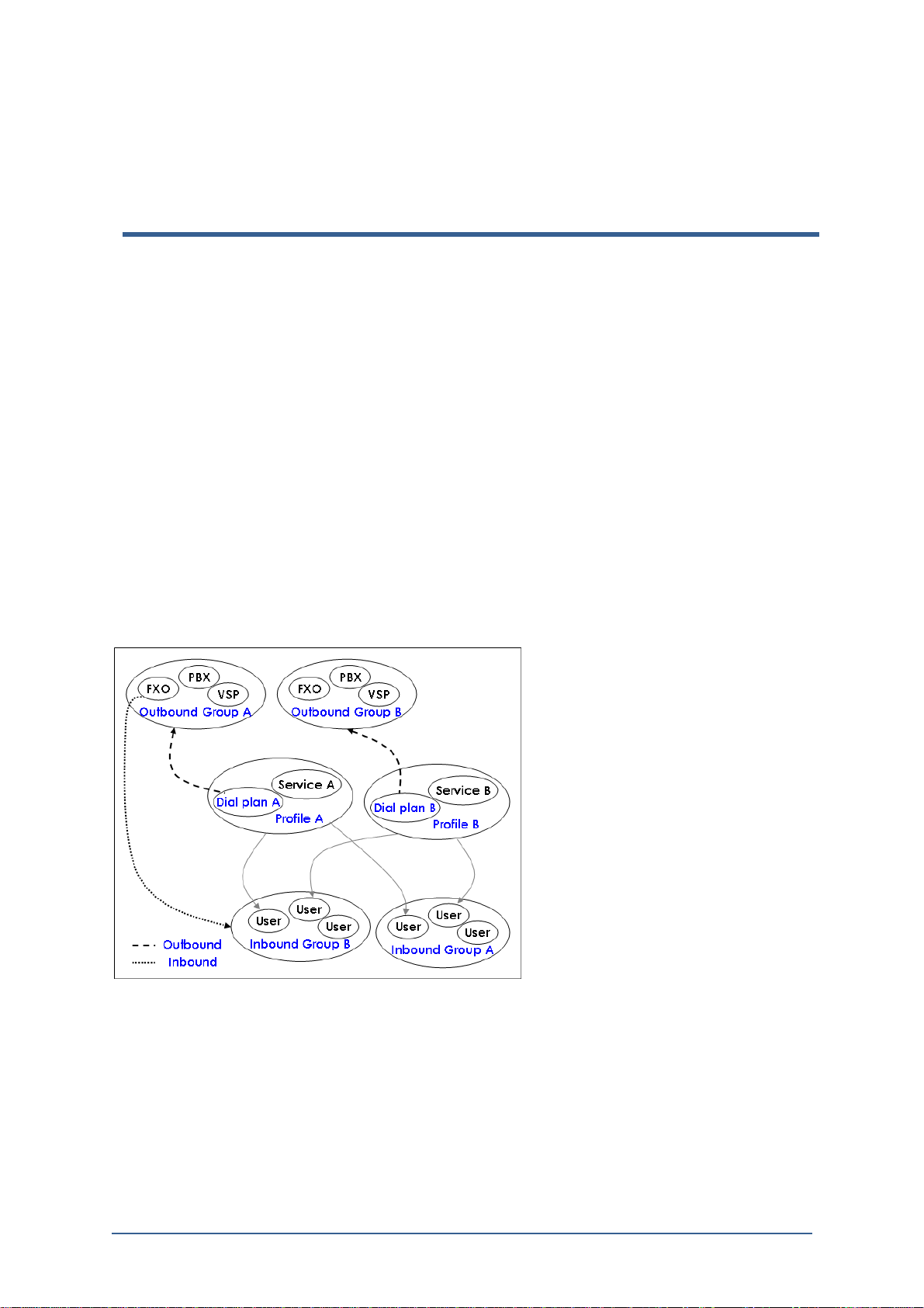
2. Service Structure and User
VOSS12 operates to connect Inbound Calls from external lines to users along with
efficient and user-friendly services, and also operates to connect external call
requests of users to Outbound Calls by applying proper dial plans.
This chapter describes Overall Service Flow and User Management.
Service Structure
On the [Basic] window of web-manager, there are five sub menus as below.
On [User], add, delete, modify terminals are users which gets services fro
VOSS12,
VOSS12 configures and manages 3 types of [Group] individually. They are
Outbound Group, Inbound Group, and Call Pick-up Group.
On [Dialplan], configures dial plans for each Outbound group
On [Profile], configures profiles such as blocking external calls which will be
applied to each user.
On [Line], configure inbound call group for each FXO lines
Management
Figure 2-1. 6 Sub-menu Structure
To configure a user, Profile which will be applied to the user must be configured
first. To configure Profile, Outbound Group must have been defined. Such complex
configuration with correlation of profiles and groups can be easily configured by
using automatic configuration function.
AdminGuide-Voss12-1.docx 13
Page 16

2. Service Structure and User Management
Structure of SIP Service
Because SIP server of VOSS12 fully follows SIP standards, terminals which follow
SIP standards can be used to work together with VOSS12. Start configuring
following with accurate understanding of SIP service structure.
UAC(User-Agent Client): Application program or terminal which requests to
send SIP messages (Caller) which ACTIVELY operates to generate/terminate
calls.
UAS(User-Agent Server): Application program or server which receives
calls from UAC (Callee) which PASSIVELY operates to accept/reject, etc.
There are terminal systems which are included in UA such as SIP phones
and/or GW(Gateway), etc.
Proxy Server: A router (Application Layer) which forwards
requests/responses of various SIP message from UA to a next node.
Redirect Server: Informs locations of different SIP servers or UA in which
destined users of requested messages exist.
Registrar Server: Register and manage users.
Location Server: A server for recording location of a current system which a
user(registered to a domain server) login to.
14
AdminGuide-Voss12-1.docx
Page 17
VOSS12 provides user friendly web interface for easy system management. Before
starting this web manager, be familiar with general set-up environment including
WAN/LAN, extension structure and so on.
Factory default of VOSS12’s LAN port is set as IP address, ‘192.168.1.10’, and
Subnet Mask ‘255.255.255.0’. And, both Administrator ID and Password are set as
‘admin’. Once initial set-up is completed, please change the system’s ID and
Password for security reason.
Note: While using web manager, if the web manager stops operating, then close
the web browser and re-log-in the web manager. This is because the Flash Player
sometimes stops playing so this is not the IP-PBX system problem.
Set-up PC’s IP Address
In order to access web manager, the PC’s IP address (ex:192.168.1.100) should be
the same domain as default IP address of VOSS12’s LAN port which
is ’192.168.1.10’. Then, connect another end of the cable from VOSS12 LAN port
to PC.
The following shows how to change PC’s IP address. (in case of using Windows
XP)
3. Web Manager
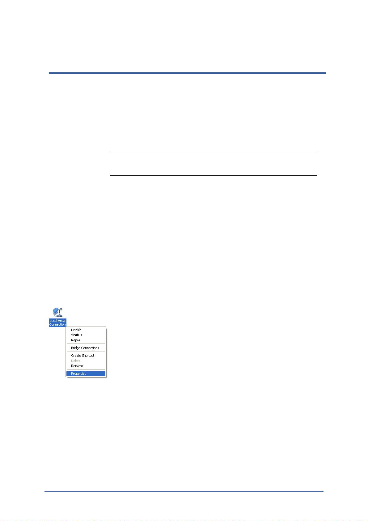
1) Go to [Start]/[Control]/[Network Connection].
2) Go to [Local Area Connection], and click right button of mouse and go to
Figure 3-1. Local Area Connection
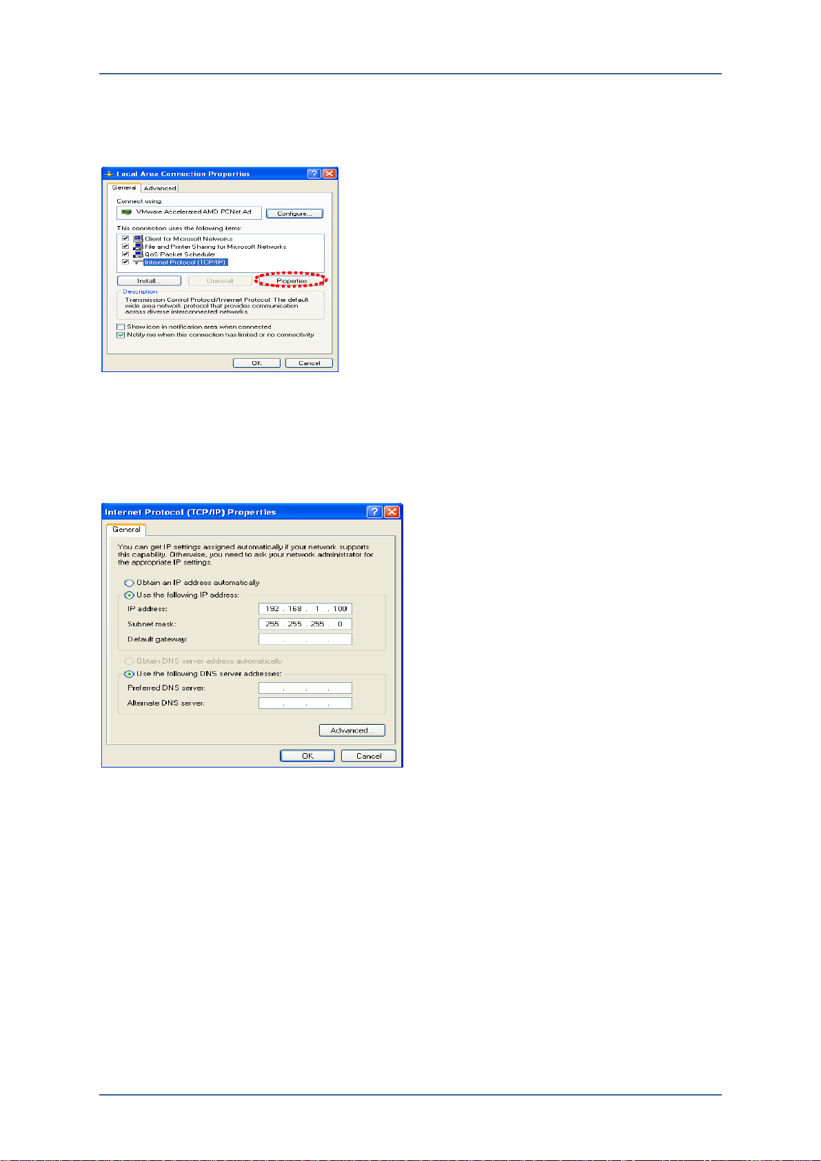
3) Go to [LocalArea Connection]/[General][Internet Protocol(TCP/IP)] and click
[Properties].
[Prosperities].
AdminGuide-Voss12-1.docx 15
Page 18
3. Web Manager
Figure 3-2. Change IP Address on PC
4) On [Internet Protocol(TCP/IP) Properties] window, check [Use the following
IP address] then, input default IP address and Subnet Mask and click [OK]
button.
Figure 3-3. Set-up IP Address
Login Web Manager
1) Open a web browser, then input‘http://192.168.1.10/’on URL bar.
2) On the following [Login] window, input User Name as ‘admin’, Password
as‘admin’, and click Login button.
16
AdminGuide-Voss12-1.docx
Page 19
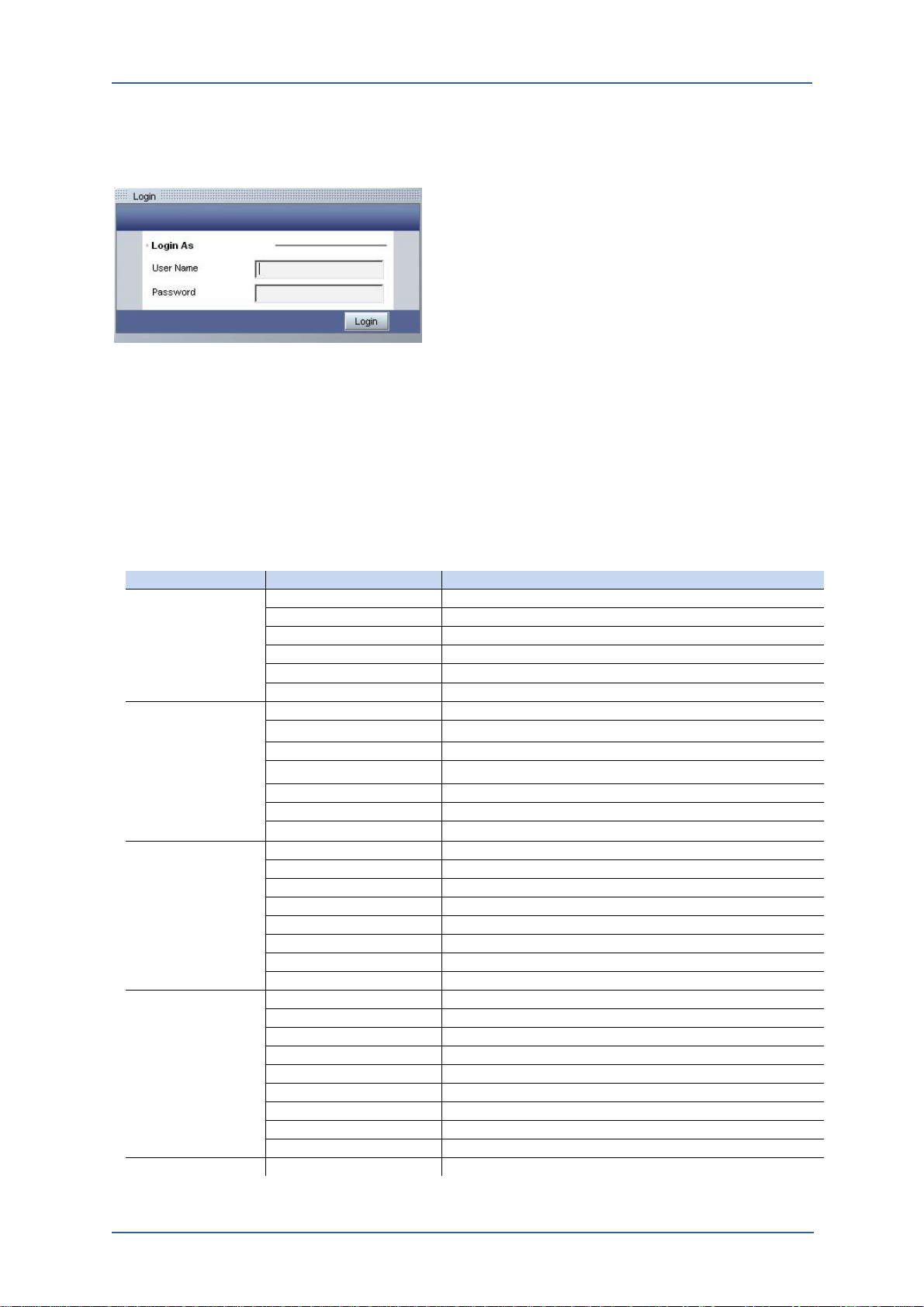
Figure 3-4. Login Web Manager
Web Manager Menu Tree
VOSS12’s Web Manager Structure is divided into 3 sections which are Main menu,
Sub menu, and View Frame. The setting can be changed by clicking the Main
menu and Sub menu on Web Manager, and by changing values on View Frame,
and then by saving the setting to apply on the system.
The following table shows Web Manager’s Main menus and Sub menus
3.Web Manager
Table 3-1. VOSS12 Web Manager Menu Tree
Main Menu Sub-Menu Setting Items
Status System System Network Phone and Line Status
Network Lan and DNS status
Event Event log of all, Notice, Warning, Error, and Critical
Active Phone Show phones connected to this system
Statistics System’s CPU load, Memory
Monitor Monitoring System, Network link, Current call, Process.
Call Log Current Show current calls
Log Show Call logs sorted by no, type, date
Call Length Per Day Accumulated Total Call Length per Day.
Call Length Per No. Accumulated Total Call Length per each Number
CDR Saved CSV file for Call Detail Records
CDR Config Backup time, Max Backup Files, CSV File Format
Record Record Logs searched by No, type, and date
Basic Profile Set services to be applied on users
User Add /Change/Delete user
Group Add/Change/Delete group
Line FXO(PSTN) and FXS(Analog Phone) settings
VSP VSP accounts and settings
Dialplan Dialplan for group and service
Feature Code Set up additional Feature Code to be used
Organization Organization structure for PBX user setting
Advanced SIP SIP Server Configuration
PBX Add a remote site PBX for Interoperating
Mail SMTP Configuration and Voicemail Configuration
Conference Managing conference number
IVR Set up IVR configuration
RAA Remote Access Authentication
Incoming Dialplan Dialplan for incoming calls
Phone Book Shared phone book for all the systems users
Emergency No Adding emergency phone number
System Network Manage the system’s Network
AdminGuide-Voss12-1.docx 17
Page 20

3. Web Manager
MOH Music on Hold setting
Time Date, Time Zone, DST, NTP configuration
Admin System Name, Web port, Language, Admin configuration
Admin Authority Assign authority for each Authority Group Name
SNMP SNMP configuration
QoS/Port Fwd. Set up QoS configuration and Port Forwarding
Monitor Set up System Monitor Configuration
Record Set up call recording configuration with NFS
Security Security Config. Set up SIP security and Kernel security configuration
ACL Add/Del Access Control List with IP address
Maintenance Reload Reloading the system
Reboot Reboot the system
Factory Default Reset the system to the Factory default
Backup/Restore Backup/restore system configuration
S/W Upgrade Upgrade the system S/W
Phone Profile Set up profiles for the connected phone
Phone S/W Manager Manage S/W for each IP-Phone model
18
AdminGuide-Voss12-1.docx
Page 21
[Status] menu shows the status information of VOSS12 such as Iine status,
Network, Active Phone, Statistics, and Monitor.
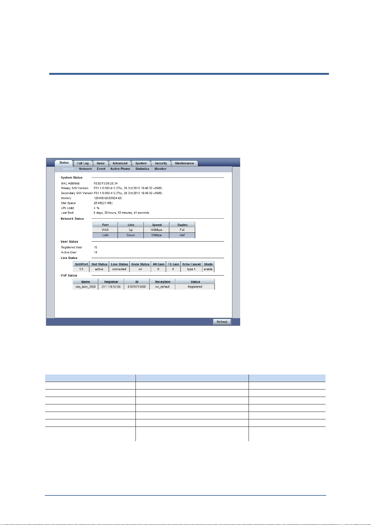
[Status]/[System]
Figure 4-1. [Status]/[System] View Frame
4. Status
■ System Status
Table 4-1. System Status Display Menu
Item Display Remarks
MAC Address Ethernet MAC Address
S/W version Version No. and Build Time
Memory Total System memory size Unit: MByte
Flash Disk Total Flash Disk size Unit: MByte
Disk Space Free space of the system memory Unit: MByte
CPU Load Current CPU Load rate Unit: %
Last Boot Total operating time from the last
Booting
■ Network Status
AdminGuide-Voss12-1.docx 19
Page 22
4. Status
Table 4-2. Network Status Display Menu
Item Display Remarks
Port Connected Port LAN, WAN
Link Ethernet link status Connected, disconnected
Speed Ethernet connection speed 10Mbps, 100Mbps
Duplex Ethernet communication type Full / Half
■ User Status
Table 4-3. User Status Display Menu
Item Display Remarks
Registered User No. of user registered in system
Active User No. of user currently using the system No. of registered Terminal
■ Line Status (FXO)
Table 4-4. Line Status Display Menu
Item Display Remarks
Slot/Port Slot/Port no. of Each FXO port
Slot Status Status of board connection into a slot
Line Status Status of line connection
Hook Status Shows On-hook or Off-hook
RX Gain RX gain value of the line Unit:dB
TX Gain TX gain value of the line Unit:dB
Echo Cancellation
Show whether Echo Canceller is enabled on
FXO board or not.
Mode The Port is used or not
■ VSP Status
Table 4-5. VSP Status Display Menu
Item Display Remarks
Name Input the name of VoIP Service Provider Space is not allowed
Registrar Registrar server address
ID User ID from VSP
Reception Input reception number or name
Status Show the line is registered to use or not.
20
AdminGuide-Voss12-1.docx
Page 23
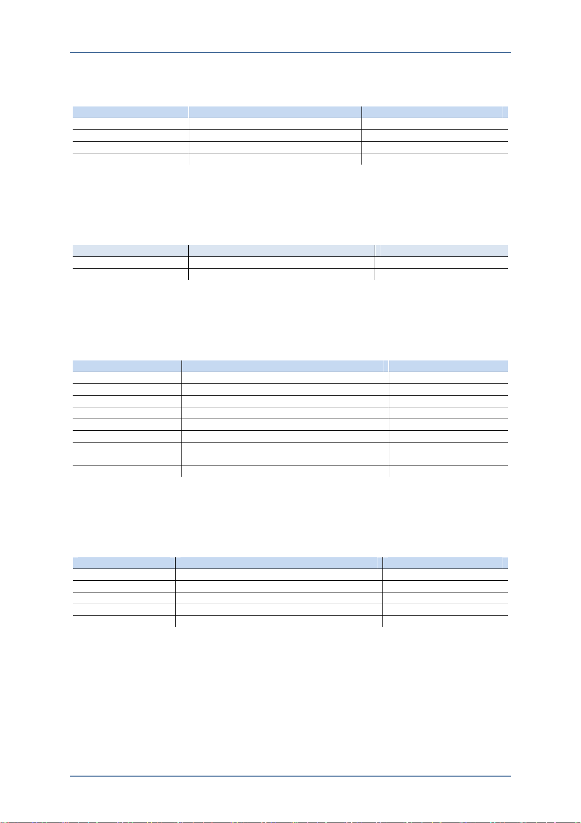
[Status]/[Network]
[Status]/[Network] menu shows the system’s network information such as
WAN/LAN/DNS.
Figure 4-2. [Status]/[Network] View Frame
4. Status
■ WAN
Table 4-6. WAN Display Menu
Item Display Remarks
IPv4 Address IP address of VOSS12 (Version 4)
IPv4 Subnet Mask IPv4 Subnet Mask
Gateway Gateway address for external connection
■ DNS
Table 4-7. DNS Display Menu
Item Display Remarks
Primary Server Primary domain name server address
Secondary Server Secondary domain name server address
■ LAN
AdminGuide-Voss12-1.docx 21
Page 24
4. Status
Table 4-8. LAN Display Menu
Item Display Remarks
IPv4 Address IP address of VOSS12 (Version 4)
IPv4 Subnet Mask IPv4 Subnet Mask
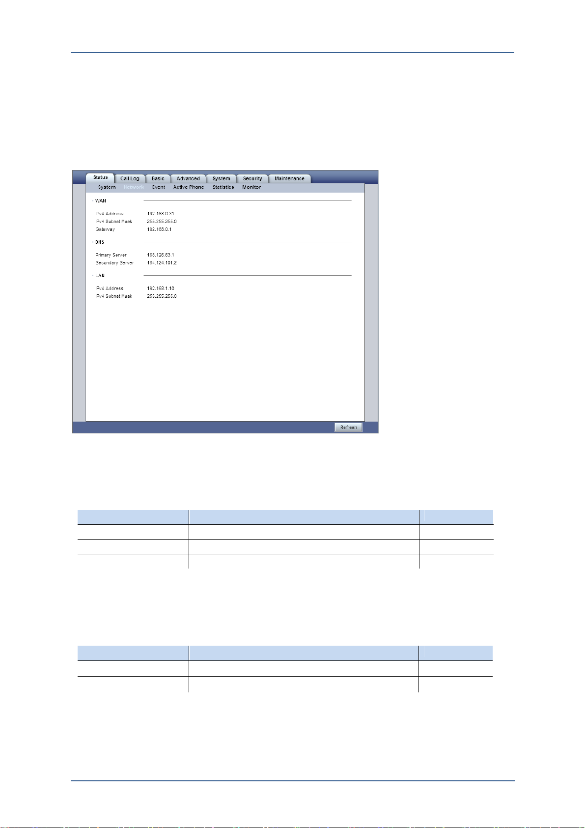
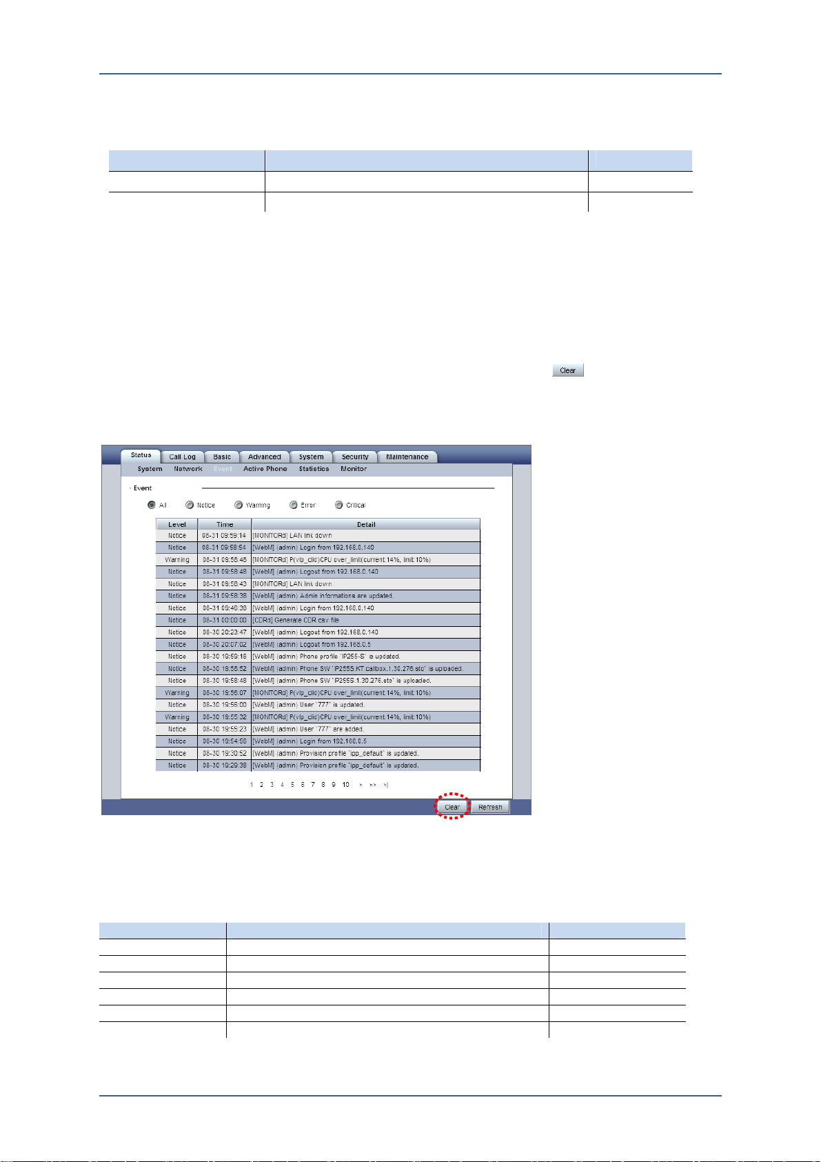
[Status]/[Event]
[Status]/[Event] menu shows all the event log(s) which is occurred during VOSS12
operating.
The system displays 20 events per page and can save 100 pages Event Log which
is total 2000 events.
If the event is over the limit (2000), then from the oldest event will be deleted to
save new event. To delete all the event logs, click the butt on the following
view frame.
Figure 4-3. [Status]/[Event] View Frame
■ Event
Table 4-9. Event Display Menu
Item Display Remarks
All Display all event logs
Notice Display status change
Warning Display wrong try for the system operation
Error Problems for the system operation
Critical Display critical problem for the system operation
Clear Delete all listed event logs
22
AdminGuide-Voss12-1.docx
Page 25
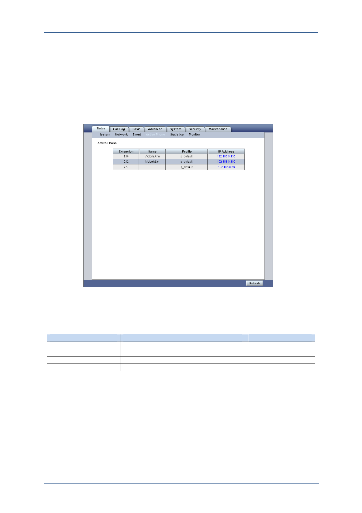
[Status]/[Active Phone]
[Status]/[Active Phone] menu shows all the active phone list which are registered
to VOSS12 as a SIP register. Which means the registered IP Phone is registered as
SIP and is able to place calls.
Figure 4-4. [Status]/[Active Phone] View Frame
4. Status
■ Active Phone Menu
Table 4-10. Active Phone Display Menu
Item Display Remarks
Extension Display all the extension numbers
Name The user name of each extension
Profile Applied service profile
IP Address Current IP address of each extension
Note: All the phones registered in VOSS12 are allowed to control on the Web
Manager. Displayed IP address on this menu is linked to IP phone’s web manager
screen, so, Administrator can easily control and manage the phone registered in
VOSS12.
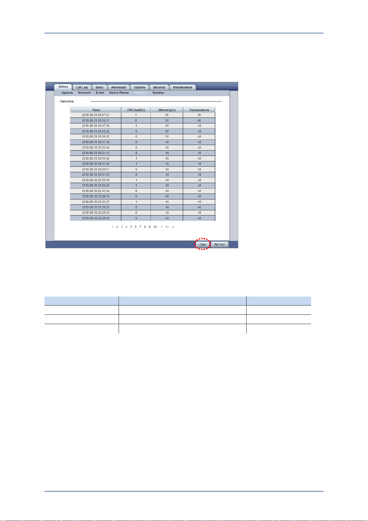
[Status]/[Statistics]
[Status]/[Statistics] menu shows accumulated statistics for VOSS12’s CPU Load,
and Memory. Each data is created per 5 minutes interval.
AdminGuide-Voss12-1.docx 23
Page 26
4. Status
In order to delete the Statistics, click Clear button on the following figure.
Figure 4-5. [Status]/[Statistics] View Frame
■ Statistics
Table 4-11. Statistics Display Menu
Item Display Remarks
Time File saving time
CPU Load (%) CPU load
Memory (%) Memory load
[Status]/[Monitor]
[Status]/[Monitor] menu shows the monitoring result for the item enabled on
[System]/[Monitor].
To update the monitoring status click Start button on the following figure, then the
system will update the monitoring status in every 10 seconds.
24
AdminGuide-Voss12-1.docx
Page 27
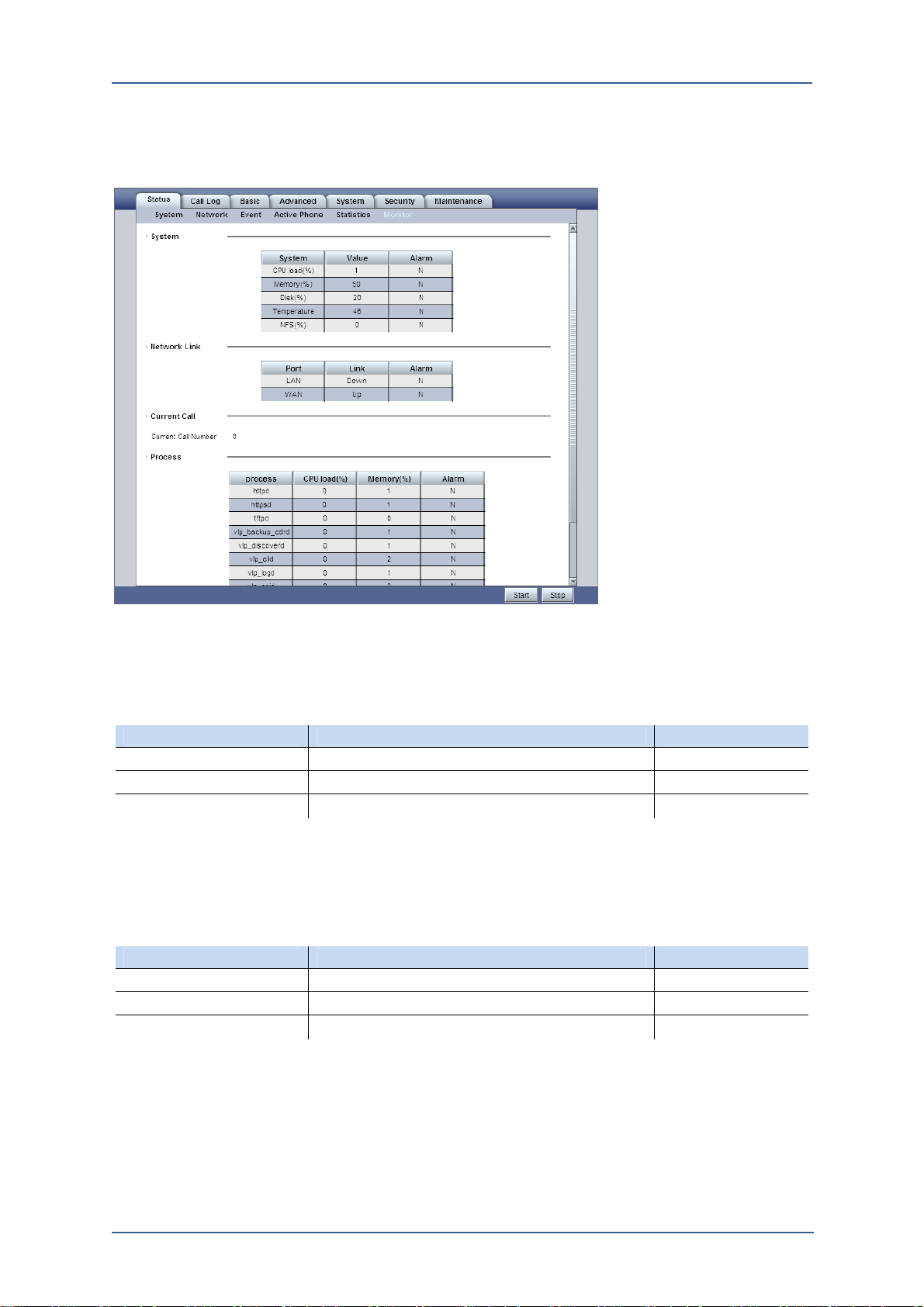
Figure 4-6. [Status]/[Monitor] View Frame
4. Status
■ System
Table 4-12. System Display Menu
Item Display Remarks
System Items for monitoring
Value The result for current monitoring
Alarm Set or Unset Alarm
■ Network Link
Table 4-13. Network Link Display Menu
Item Display Remarks
Port Ethernet Port
Link Network Status
Alarm Set or Unset Alarm
AdminGuide-Voss12-1.docx 25
Page 28

4. Status
■ Concurrent Call
Table 4-14. Concurrent Call Display Menu
Item Display Remarks
Concurrent Call Number Number of current concurrent call.
■ Process
Table 4-15. Process Display Menu
Item Display Remarks
Process The process name for monitoring
CDP Load(%) CPU load
Memory(%) Memory load
Alarm Set or Unset Alarm
26
AdminGuide-Voss12-1.docx
Page 29
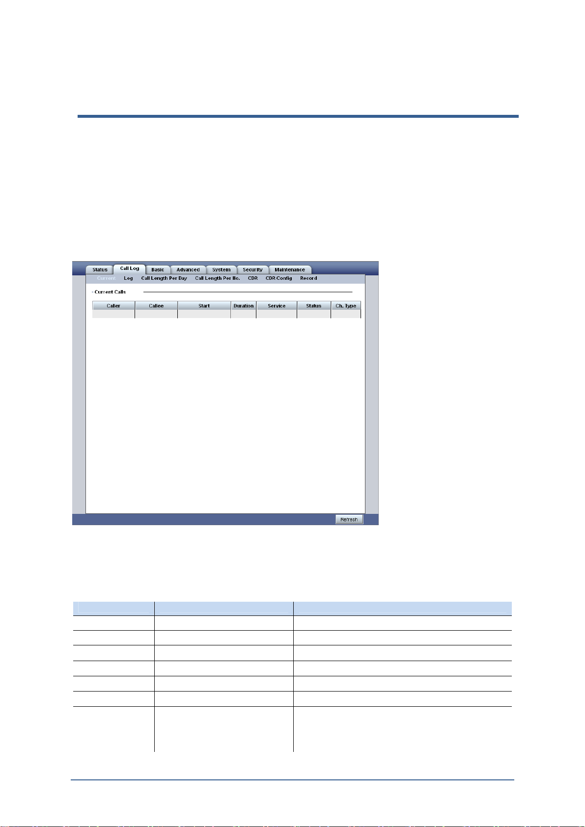
[Call Log] menu is to check and manage Call Logs.
[Call Log]/[Current]
[Call Log]/[Current] menu shows the current calls.
Figure 5-1. [Call Log]/[Current] View Frame
5. Call Log
■ Current Call
Table 5-1. Current Call Display Menu
Item Display Remarks
Caller Caller’s Phone Number
Callee Callee’s Phone Number
Start Call starting time
Duration The call duration
Service Applied service Dial/Pickup/Transfer/Parking/IVR so on
Status Call status
Ch. Type Channel Type Ext: Extension
VSP: A channel connected through VSP
FXO: A channel connected through FXO
PBX: A channel connected through PBX
AdminGuide-Voss12-1.docx 27
Page 30
5. Call Log
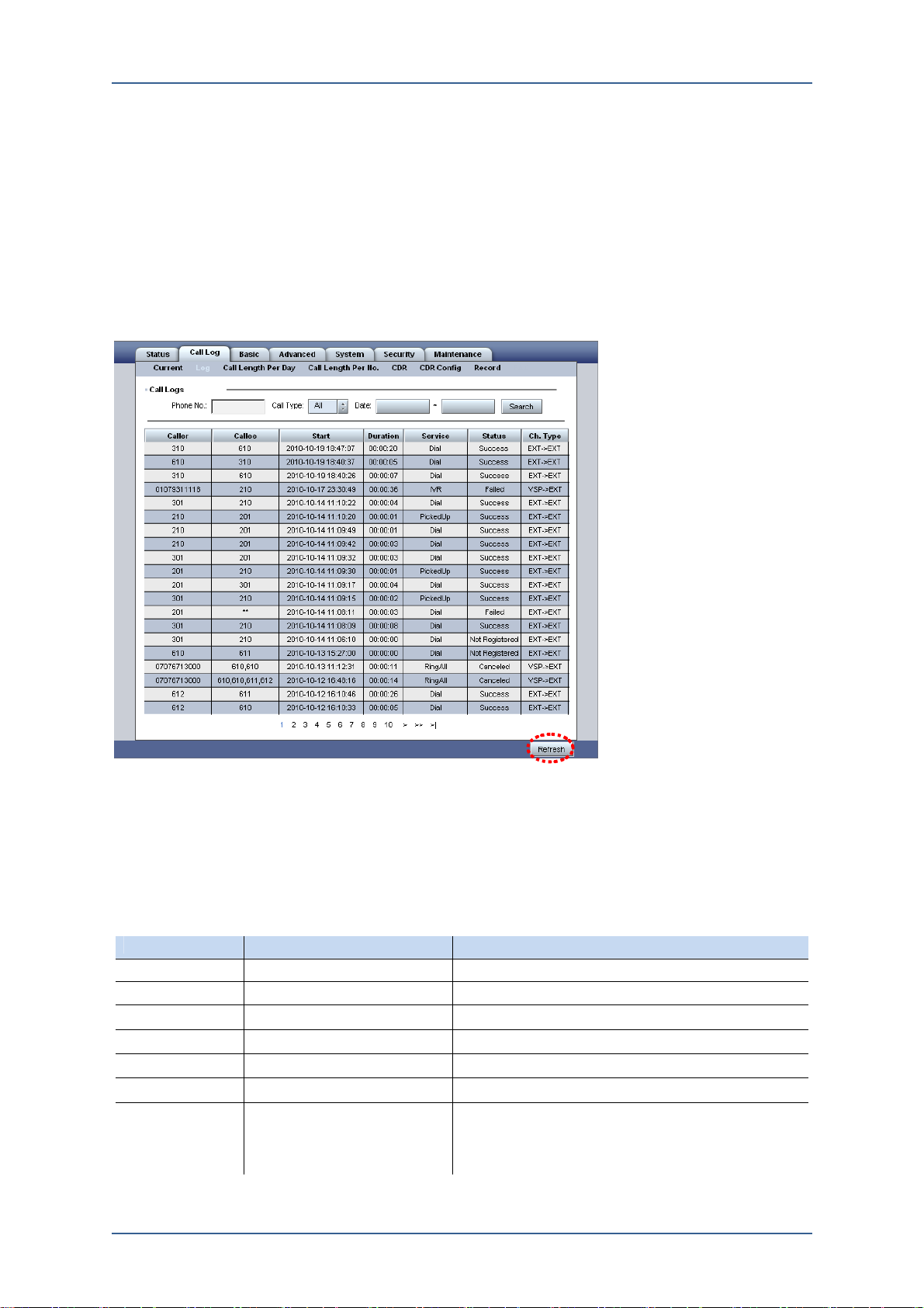
[Call Log]/[Log]
[Call Log]/[Log] menu shows call logs. And, the logs can be searched by a certain
number, caller/callee, or date.
Figure 5-2. [Call Log]/[Log] View Frame
If you want to clear the searching condition, click Refresh button.
■ Call Log
Table 5-2. Call Log Display Menu
Item Display Remarks
Caller Caller’s Phone Number
Callee Callee’s Phone Number
Start Call starting time
Duration The call duration
Service Applied service Dial/Pickup/Transfer/Parking/IVR so on
Status Call status
Ch. Type Channel Type Ext: Extension
VSP: A channel connected through VSP
FXO: A channel connected through FXO
PBX: A channel connected through PBX
28
AdminGuide-Voss12-1.docx
Page 31

[Call Log]/[Call Length Per Day]
[Call Log]/[Call Length Per Day] menu shows the statistics on total incoming call,
outgoing call, call length, total call count and total length per day. And, the length
can be searched by certain date.
Figure 5-3. [Call Log]/[Call Length Per Day] View Frame
5. Call Log
■ Call Length Per Day
Table 5-3. Call Length per Day Display Menu
Item Display Remarks
Date Date
In. Count Number of incoming call
In. Length Total length of all incoming call
Out .Count Number of outgoing call
Out. Length Total length of all outgoing call
Total Count Number of total incoming & outgoing call per day
Total Length Total length of call per day
[Call Log]/[Call Length Per No.]
[Call Log]/[Call Length Per No.] shows the statistics on total incoming call,
outgoing call, call length, total call count and total length per each phone number.
And, the length can be searched by certain phone number or date.
AdminGuide-Voss12-1.docx 29
Page 32

5. Call Log
Figure 5-4. [Call Log]/[Call Length Per No] View Frame
■ Accumulated Call Length Per Number
Table 5-4. Call Length Per Number Display Menu
Item Display Remarks
Phone No. Phone Number
In. Count Number of incoming call
In. Length Total length of all incoming call
Out .Count Number of outgoing call
Out. Length Total length of all outgoing call
Total Count Number of total incoming & outgoing call per day
Total Length Total length of call per day
[Call Log]/[CDR]
[Call Log]/[CDR] menu shows the call log as CSV file format. To use this menu,
the CDR config menu on the next chapter 6.6 should be set up, saving CDR as
CSV file format.
On [Call log]/[CDR] menu, you can check CSV file list and can down load the file.
The CSV file can be used for call charging data.
Figure 5-5. [Call Log]/[CDR] View Frame
30
AdminGuide-Voss12-1.docx
Page 33

5. Call Log
■ CDR
Table 5-5. CDR Display Menu
Item Display Remarks
CSV File Name File name of call detail records
Size The file size
Time Shows when the file is saved
[Call Log]/[CDR Config]
[Call Log]/[CDR Config] menu is for setting up CDRs to be saved as CSV file.
AdminGuide-Voss12-1.docx 31
Page 34

5. Call Log
Figure 5-6. [Call Log]/[CDR Format] View Frame
Backup Time: System creates one backup CSV file per each day. On this
menu, set up the time for creating backup CSV file. (00~23 hour standard)
Max Backup Files: Set up maximum number of CSV file. This system
creates a CSV file per day, so the maximum number is the same as how many
days’ call detail records are saved in the system. The number of maximum
Backup File is 60, so the 60 days CDR can be saved in this system. If this
value is 0 then the system will not save CDR backup file.
CSV File Format: file format for saving CDR data in CSV file.
[Call Log]/[Record]
[Call Log]/[Record] is to check recording log and managing the recording file.
32
AdminGuide-Voss12-1.docx
Page 35

Figure 5-7. [Call Log]/[Record] View Frame
5. Call Log
■ Record Menu
Table 5-6. [Call Log]/[Record] View Frame
Item Display Remarks
Recorder The person active this recording feature
Caller Caller’s number
Callee Callee’s number
Start The time started recording
Duration Recording Duration
Record Recording file name
AdminGuide-Voss12-1.docx 33
Page 36

[Basic] menu is for basic setting up to place or receive call through IP-PBX’s
Profile, User, Group, and Dialplan.
[Basic]/[Profile]
[Basic]/[Profile] menu is to manage profiles. Profile means a grouping of service
and dialplan that will be used for users registered in VOSS12. For example, if a
profile is enabled Conference, Voicemail and placing outgoing call though VSP
then all the users using the profile will be able to use Conference, Voicemail and
VSP account to place outgoing calls.
Adding Profile
VOSS12 provides basic profile through Default profile. However, if there is
another required service, dialplan or combination, then add a new profile.
1) Go to [Basic]/[Profile].
6. Basic
2) Then, the following profile will be displayed.
Figure 6-1. [Basic]/[Profile] View Frame
3) Click Add button to add a new profile.
4) Input all the required information on the following view frame.
34
AdminGuide-Voss12-1.docx
Page 37

Figure 6-2. New Profile Configuration
6. Basic
■ Profile Config
Name: Input a new name of profile.
Dialplan: Select Dialplan(s) for Outgoing calls.
Basic Feature: Select either use basic additional features or not.
Conference: Select either use conference call feature or not.
Voicemail: Select either use voicemail or not.
Parking: Select either use parking feature or not.
Forwarding: Select either ruse Forwarding feature or not.
Intercom: Select either use Intercom feature or not.
Threeway: Select either user 3way call for FXS terminal or not. 3way feature
is a feature that one FXS terminal is connected with two call, then hook flash
on FXS terminal then the calls will be connected as 3way. However, this
feature is working when the option is checked Yes. For your information,
hook flash function on FXS terminal is working as below in accordance to
using three way.
Using 3way Call – working as 3way.
Not using 3way call – working as hold function.
Virtual Caller ID No.: Input a virtual caller ID. After input this caller ID, if
the same profile users place outgoing calls then, this virtual caller ID will be
displayed as caller ID.
5) Click Save button to save the setting.
AdminGuide-Voss12-1.docx 35
Page 38

6. Basic
Deleting Profile
To delete a profile, follow the instruction below.
1) Go to [Basic]/[Profile].
2) Then, the current profile will be displayed as Figure 6-1.
3) On the displayed profile, click the right X sign on the destined profile.
Change Profile Information
The following information can be changed on this profile menu.
Dialplan
Basic Feature
Conference
Voice Mail
Parking
Forwarding
Intercom
Threeway
Virtual Caller ID.
Figure 6-3. Change Profile
1) Go to [Basic]/[Profile].
2) Then, the current profile will be displayed as the following figure.
3) Click on the destined profile.
4) Then, change the information on the following Figure 6-3.
5) Click Save button to save setting.
36
AdminGuide-Voss12-1.docx
Page 39

[Basic]/[User]
The meaning of User in VOSS12 is extension number.
Basically, VOSS12 has pre-registered 5 users (extensions); 100~104, so no need to
add new user for this system configuration.
Adding User
The users can communicate with their extension number users, and place outgoing
calls through PSTN or VSP. Adding use is divided by two; Add and Multi-add.
Adding One User
To add a user, follow the instruction below.
1) Go to [Basic]/[User] menu.
Figure 6-4. [Basic]/[User] View Frame
6. Basic
2) And click Add button to add a user.
3) Input information on the following view frame.
AdminGuide-Voss12-1.docx 37
Page 40

6. Basic
Figure 6-5. Adding One User
■ User Config
Extension: Input an extension number.
DID/DOD No.: DID stands for Direct Inward Dialing, DOD stands for Direct
Outward Dialing and this number is a personal direct incoming/outgoing
number. So, VSP should support this service, and if VSP supports this service,
each number should be assigned to each user to use this function.
Anonymous CID: Select either using caller ID display or not. If this function
is checked, and the caller place outgoing call though VSP, then the callee
can’t see the caller ID.
Name: Input a user name. This name will be used as display name among
extension users.
E-Mail: If the user is received Voicemail, then the VOSS12 will send voice
mail to this email account.
Password: Input password for SIP register. For the security reason, use a
password which is more complicated and difficult to guess. VOSS12 also
creates a random password so click Gen button to get a random password.
38
AdminGuide-Voss12-1.docx
Page 41

6. Basic
The password in this setting should be the same on the extension’s IP-Phone
then, the phone can be SIP registered in VOSS12
V.M Password: Input a password for accessing Voice Mail.
Organization: The department or division the user is belonging to.
Ring Timeout: Phone will be ringing during this set time..
DTMF mode: Select a DTMF mode to use.
Profile: Select a profile for the user.
■ Call Forwarding
DND: Check to use Do Not Disturb function.
Always: Always forwarding all the incoming calls.
Busy: Forwarding calls when the line is busy.
No Answer: Forwarding calls after ring timeout when the user doesn’t answer
the phone.
Error: Forwarding calls when the system has error.
Time based: Forwarding calls in accordance to the set time.
■ User Music
On Hold: Select Music on Hold.
On Ringback: Select Caller Ring music.
Time based: Select music in accordance to the set time.
4) Click Save button to save the setting.
Adding multiple users at once
VOSS12 provides Multi-Add function button to allow adding more than one user at
once.
1) Go to [Basic]/[User] menu.
AdminGuide-Voss12-1.docx 39
Page 42

6. Basic
Figure 6-6. Using Multi-Add button
2) Click Muti-Add button.
3) Then, input the required information on the following view frame.
Figure 6-7. Adding Users by using Multi-Add
40
AdminGuide-Voss12-1.docx
Page 43

■ Multi User Add
Extension: Input the range of extension number to add. Once you input the
beginning number and the ending number, then the system will create
numbers between the beginning number and ending number automatically.
DID/DOD No.: refer to the above ‘Adding one user’ menu.
E-Mail: refer to the above ‘Adding one user’ menu.
Profile: refer to the above ‘Adding one user’ menu.
User Provision: refer to the above ‘Adding one user menu.
Ring Timeout: refer to the above ‘Adding one user’ menu.
DTMF Mode: refer to the above ‘Adding one user’ menu.
4) Click Add button on right to save the setting
Figure 6-8. Adding Users by using Multi-Add
6. Basic
5) After adding a user on the above view frame, click Save button to save the
setting.
Change User Information
The followings are changeable information on User menu.
DID/DOD No.
Anonymous CID
Name
E-mail
Password
V.M Password
Organization
Ring Timeout
DTMF Mode
Profile
User Provision
Call Forwarding
User Music
1) Go to [Basic]/[User] menu.
AdminGuide-Voss12-1.docx 41
Page 44

6. Basic
2) Click a user’s extension number to change.
3) Change the information on the following view frame.
Figure 6-9. User Information View Frame
Deleting User
42
4) After Change the information, click Save button to save the setting.
1) Go to [Basic]/[User] menu.
2) Then, all the registered users will be displayed as below.
AdminGuide-Voss12-1.docx
Page 45

Figure 6-10. User Information View Frame
6. Basic
3) Check the right end Check box of the destined Extension number by clicking,
and click Delete in the bottom.
4) If you click All on the right top of the above view frame, all the extensions
will be selected, and if you click Delete button, then all the selected users will
be deleted.
[Basic]/[Group]
VOSS12 has the following 4 types of group, and they can be managed on
[Basic]/[Group] menu.
Incoming Group: A group for receiving calls.
Outgoing Group: A group of service line (VSP/FXO/PBX) to place outgoing
calls.
Pickup Group: A group for using Pickup function.
Group Intercom: The members in the same Intercom Group, all of them can
be connected with intercom by pressing pr-registered extension.
Adding Group
Adding Incoming Group
To add a new incoming group, follow the introduction below.
1) Go to [Basic]/[Group] menu.
Figure 6-11. [Basic]/[Group] – Incoming Group View Frame
AdminGuide-Voss12-1.docx 43
Page 46

6. Basic
2) Click the Add button on the above view frame.
Figure 6-12. Adding Incoming Group
3) Input a name to be used in this incoming call group, and select a type for this
incoming group then the Ring Type and Extension menu will be expanded.
Then select one Ring Type, and select an extension for this incoming group.
4) Click Save button to save the setting.
44
AdminGuide-Voss12-1.docx
Page 47

Adding Outgoing Group
To add an outgoing group, follow the instruction below.
1) Go to [Basic]/[Group] menu.
Figure 6-13. [Basic]/[Group] – Outgoing Group View Frame
6. Basic
2) Click the Add button on the above view frame.
Figure 6-14. Adding outgoing Group View Frame
3) Input a name for the new outgoing group, and select the Type. Then, the Dial
Type will be expanded. Select a suitable type among 3 dial types.
4) Click Save button to save the setting.
AdminGuide-Voss12-1.docx 45
Page 48

6. Basic
Adding Pickup Group
To add a pickup group, follow w the instruction below.
1) Go to[Basic]/[Group] menu.
Figure 6-15. [Basic]/[Group]–Pickup Group View Frame
2) Click Add button on the bottom of the above view frame.
Figure 6-16. Adding Pickup Group
3) Input a name and select pickup as a Type.
4) Click Save button to save the setting.
Adding Intercom Group
To add an Intercom Group, follow the instruction below.
1) Go to [Basic]/[Group] menu.
46
AdminGuide-Voss12-1.docx
Page 49

Figure 6-17. [Basic]/[Group] – Intercom Group View Frame
6. Basic
2) Click the Add button on bottom of the above view frame.
Figure 6-18. Adding Intercom Group View Frame
3) Input a name for this intercom group, and select intercom as a type. Then,
extension menu will be expanded and choose an extension number for this
Intercom Group.
4) Click Save button to save the setting.
Change Group
Change Incoming Group
To change incoming group, follow the instruction below.
1) Go to [Basic]/[Group] menu.
AdminGuide-Voss12-1.docx 47
Page 50

6. Basic
Figure 6-19. Change Incoming Group View Frame
■ Group Config
Ring Type: This menu is to set up a call routing policy for the same group me
members. The followings are ring type menu.
Hunt: For an incoming call, the system will connect the call with an idle
mode line among hunt group members. But the system will try connecting
the call in accordance to registered order first.
Circular-Hunt: The same with Hunt but this Circular Hunt remember the
last connected line, and tries connecting from the next number.
Ring-All: All the group members’ phones will be ringing simultaneously
for the incoming call. And if a member answers the call, then the ringing
will be stopped.
Random: The Incoming calls will be connected to a random group user.
Circular-Hunt(Call Fwd. Enabled): If one group member set Call
forwarding on the user’s phone, then incoming calls will be going to the
Call forwarding enabled user and the other members phones will not be
ringing for the incoming calls. If Call forwarding is not included, this
feature is the same with Random.
■ Member Config
A representative extension number for this incoming group. So, if this number
receives an incoming call then the call will be routing to the group member
according to the ring type.
■ Music on Ringback
This menu is to set up a kind of caller ring which allows the caller to hear the
music while the call is connected. This menu is the same with Music on
Ringback Config on [System]/[MOH]menu, so you can choose either menu
for setting up Music on Ringback configuration.
48
AdminGuide-Voss12-1.docx
Page 51

■ Member Config
For this incoming group member, only user(s) can be added. To add a user,
■ Call Forwarding: input call forwarding number according to the following
case.
Always: Always forwarding all the incoming calls.
Busy: Forwarding calls when all the lines are busy.
No Answer: among group members, if nobody answers the incoming call
Error: Forwarding calls when the system has error.
Timebased: Forwarding calls in accordance to the set time.
2) Click Update button to save the setting.
Change Outgoing Group
6. Basic
select a member name and click Add button. To delete a user, click right X on
the user number.
then the call will be forwarded to this number.
To change outgoing group, follow the instruction below.
1) Go to [Basic]/[Group]menu.
Figure 6-20. Change Outgoing Group View Frame
■ Group Config
Dial T ype
Linear: Placing calls in accordance to the pre-registered order. But this
type always starts placing calls from the 1
st
registered number.
Circular: This type remembers the last calls placed line, and tries placing
call from the next registered line which was not used.
User Reception VSP: each user has individual VSP.
AdminGuide-Voss12-1.docx 49
Page 52

6. Basic
To use this type, the reception type on [Basic]/[VSP] menu should be set
as User and select an extension user as Name. Then, incoming calls to the
VSP account will be routing to the user. And if the VSP number is set as a
group member of Outgoing group, then the user place calls and receives
calls though this VSP account. So, this concept is a kind of DID/DOD.
■ Member Config
Member Config: Select a member of this outgoing group among
FXO/VSP/PBX then click Add button. To delete a member, click X on
destined member.
2) Click Update to save the setting.
Change Pickup Group
To change Pickup group, follow the instruction below.
1) Go to [Basic]/[Group] menu.
Figure 6-21. Change Pickup Group View Frame
■ Member Config
Member Config: For Pickup group, only users can be added. To add a user,
click Add button on the destined user’s extension number. To delete a user,
click the right X on destined user.
2) Click Update button to save the setting.
50
AdminGuide-Voss12-1.docx
Page 53

Change Intercom Group
To change intercom group, follow the instruction below.
1) Go to [Basic]/[Group] menu.
Figure 6-22. Change Intercom Group View Frame
6. Basic
■ Group Config
Extension: A representative number for this intercom group. So if call this
■ Member Config
Member Config: For intercom group, only users can be added. To add a user,
2) Click Update button to save the setting.
Deleting Group
To delete a group, delete the group members first. After deleting all the group
member, then delete the group.
Deleting Incoming Group
To delete incoming group, follow the instruction below.
1) Go to [Basic]/[Group] menu.
number then all the group members will be connected all together.
click Add button on the destined user’s extension number. To delete a user,
click the right X on destined user.
AdminGuide-Voss12-1.docx 51
Page 54

6. Basic
Figure 6-23. Deleting Incoming Group View Frame
2) Choose a destined incoming group. Before deleting the group name, delete all
the members first by clicking X, and click Update button to save the setting.
3) Choose the destined incoming group again, then click bottom Delete button to
delete the incoming group.
Deleting Outgoing Group
To delete outgoing group, follow the instruction below.
1) Go to [Basic]/[Group] menu.
52
AdminGuide-Voss12-1.docx
Page 55

Figure 6-24. Deleting Outgoing Group View Frame
6. Basic
2) Choose a destined outgoing group to delete. Before deleting the group name,
3) Choose the destined outgoing group again, and click the bottom Delete button
Deleting Pickup Group
To delete pickup group then follow the instruction below.
1) Go to [Basic]/[Group] menu.
delete all the group members first by clicking X on each member name. After
deleting all the members, click Update button to save the setting.
to delete the outgoing group.
AdminGuide-Voss12-1.docx 53
Page 56

6. Basic
Figure 6-25. Deleting Pickup Group View Frame
2) Choose a destined pickup group to delete. Before deleting the group name,
delete all the group members first by clicking X on each group member. And
after deleting all the member, click Upgrade button to save the setting.
3) Choose the destined pickup group again, and click the bottom Delete button to
delete the outgoing group.
Deleting Intercom Group
To delete intercom group, follow the instruction below.
1) Go to [Basic]/[Group] menu.
54
AdminGuide-Voss12-1.docx
Page 57

Figure 6-26. Deleting Intercom Group View Frame
6. Basic
2) Choose a destined intercom group to delete. Before deleting the group name,
delete all the group members first by clicking X on each member name. After
deleting all the members, click Update button to save the setting.
3) Choose the destined intercom group again, and click the bottom Delete button
to delete the intercom group.
[Basic]/[Line]
This menu is to manage connected FXO/FXS.
Change Line Setting
Change FXO Setting
To change FXO setting, follow the instruction below.
1) Go to [Basic]/[Line] menu.
2) Click Slot/Port number, then the following view frame will be popped up. On
the following view frame, line setting can be checked and changed.
AdminGuide-Voss12-1.docx 55
Page 58

6. Basic
Figure 6-27. Change FXO Setting View Frame
■ FXO Config
Mode: Click to use FXO port.
Hook Status: Click Hook Ideal mode according to each nation’s environment.
RX Gain: Set up the volume from the Line to VOSS12 (for phone).
TX Gain: Set up the volume from VOSS12 to the Line (for PSTN network).
CID RX Gain: Set up standard level for recognizing CID information when
receiving CID.
CID Type: Set up CID type as Korea: Telcordia, Erupe: ETSI, England: SIN
227, Japan: NTT.
Echo Cancellation: Echo is listening user own voice during a call, there are
two echo cancellation methods; Type1 and Type2(ES).
Type1 – Normal echo cancellation method
Type2(ES) – An Echo Cancellation which is added suppressor. So, this
improves echo cancellation function but can’t use Double–Talk function.
VAD/CNG: Click if using VAD(Voice Activity Detection) and CNG(Comfort
Noise Generation).
Area Code: Input PSTN area code
Prefix: Input a prefix number to use for PSTN line outgoing call.(eg.’9’)
Reception Type: Choose one reception type among
[User|Group|IVR|PBX|VSP/FAX].
Reception Name: Choose one reception name in accordance to reception
type.
Distinctive Ring Header: A header to set up different bell sound for FXO
line incoming call. Choose one from “Alert-Info: http://127.0.0.1/bellcoredr1”to “Alert-Info: http://127.0.0.1/bellcore-dr10”.
Country: Choose a country(where the system installed) to apply local
disconnection tone.
56
AdminGuide-Voss12-1.docx
Page 59

6. Basic
Disconnect Detect Type: When a call is ended, PSTN sends a signal to let
FXO to detect the call is ended. The followings are disconnect detect methods.
Link – PSTN disconnect the power supply for a short time and connect
again.
Polarity – PSTN sends Inverse Polarity.
All – Use both Link and Polarity
Custom Disconnect To ne: If the chosen disconnect tone doesn’t disconnect
the call, then use this menu to detect disconnect tone. The followings are
disconnect tone formats.
Input Format: [Loop Pause Freq1 Level1 Freq2 Level2 Freq3 Level3
Freq4 Level4 Cadence1 Paly1 Cadence2 Play2 …]
Example: 0 0 480 -11 620 -9 0 0 0 0 500 12 500 0
Loop: 0 means the disconnect tone will be played continuously, and
bigger than number 1 means disconnect tone will be played the number of
times.
Pause: a pause time at the end of disconnect tone play. The unit is
millisecond.
Freq: Every country uses different Frequency. If you want to use a
customized frequency which differ with a country’s Frequency, then input
the frequency on this menu. The unit is Hz.
Level: A level to detect disconnect tone, range is normally from -09~-
11dB.
Cadence: Disconnect tone playing duration. Input Maximum 6 cadences.
The unit is millisecond.
Play: Define disconnect tone playing method. If the value is 0 then,
system will not play any tone during the defined time in Cadence. The
value is not 0, for example “12” means playing Freq1 and Freq2
together. And, the value includes “x”at the end, like “12x”, then play
the tone after modulating Freq1 with Freq2.
Change FXS Setting
To change FXS setting, follow the instruction below.
1) Go to [Basic]/[Line] menu.
2) Click Slot/Port number then, the follow view frame will be popped up. On the
following view frame, line setting can be checked and changed
AdminGuide-Voss12-1.docx 57
Page 60

6. Basic
Figure 6-28. Change FXS Setting View Frame
■ Line Config
Extension: choose an extension number for this FXS.
Dial Timeout: Input time which will dial automatically after the set time
without pressing send button.
Digit Timout: Maximum time interval between digits.
Hook Flash Interval: This function is used for putting the current call on
hold (press Hook switch rapidly and off). Input time in milli-second for Hook
switch interval.
RX Gain: Set up the volume from the Line to VOSS12 (for phone).
TX Gain: Set up the volume from VOSS12 to the Line (for PSTN network).
CID RX Gain: Set up standard level for recognizing CID information when
receiving CID.
CID Type: Set up CID type as Korea: Telcordia, Erupe: ETSI, England: SIN
227, Japan: NTT
Echo Cancellation: Echo is listening user own voice during a call, there are
two echo cancellation methods; Type1 and Type2(ES).
Type1 – Normal echo cancellation method.
Type2(ES) – An Echo Cancellation which is added suppressor. So, this
improves echo cancellation function but can’t use Double–Talk function.
VAD/CNG:VAD/CNG: Click if using VAD(Voice Activity Detection) and
CNG(Comfort Noise Generation).
Country: Select current Country
Dial Pattern: Input a dial pattern for outgoing call. (Refer to the Appendix B)
Line Card Reset
While using VOSS12, if its line care has a problem, then don’t need to reboot the
system, just need to reset the line card. To reset the line card, follow the instruction
below.
1) Go to [Basic]/[Line] menu.
58
AdminGuide-Voss12-1.docx
Page 61

2) Then the following view frame will be popped up.
Figure 6-29. Line Card Reset View Frame
6. Basic
3) Click Reset button on the above view frame, then the following view frame
will be popped up. To reset a line card, select a slot number on the following
view frame and click Reset button.
Figure 6-30. Selecting Slot View Frame
[Basic]/[VSP]
VSP stands for VoIP Service Provider. In order to use VSP’s service to place a call,
apply a local VSP service to get an account first, and register the account to the
system. [Basic]/[VSP] menu is for setting up VSP account.
Adding VSP
Input the VSP account information on following VSP menu.
1) Go to [Basic]/[VSP] menu.
AdminGuide-Voss12-1.docx 59
Page 62

6. Basic
Figure 6-31. VSP Configuration View Frame
2) Click Add button to add a VSP.
60
AdminGuide-Voss12-1.docx
Page 63

Figure 6-32. Adding VSP View Frame
6. Basic
■ VSP Config
Name: Input VSP account’s name.
Registrar: Input registrar Server’s address/port.
Proxy: Input Proxy Server/Port.
Out Proxy : Input Out Proxy server’s address/port.
ID: Input VSP number assigned by VSP.
Auth ID: Assigned ID from VSP for server authorization.
Password: Input the password assigned from VSP.
Virtual Caller ID No.: Virtual caller ID which will be displayed to callee’s
phone. (To use this function, SIP connect menu is set as “Yes” on VSP menu.)
Dial Timeout: Input time which will dial automatically after the set time
without pressing Send button.(in seconds)
Distinctive Ring Header: Assign a different bell sound for all the incoming
call through VSP line. Choose one among 10 kinds of bell sounds;
from“Alert-Info: http://127.0.0.1/bellcore-dr1” to “Alert-Info:
http://127.0.0.1/bellcore-dr10”.
Ping Interval: if the value is not ‘0’ then this system will send SIP Option
Request to VSP every ping interval time.
Register Expiry:Input re-register interval so the system will send SIP
Register Request to VSP.
Reception T ype: Choose a reception type among [User/Group/IVR/PBX].
Reception Name: Choose a Reception Name among [USER | GROUP | IVR |
AdminGuide-Voss12-1.docx 61
Page 64

6. Basic
PBX]
DTMF Mode: Choose a DTMF mode for pressing number during a call.
(Default:rfc2833)
SIP Connect: For setting DID account when using VSP Trunk.
SIP Connect Header: For setting up a header which will be used in SIP
Connect feature.
User Session Timer: For setting up the session timer for each VSP. This
differs with the session timer on [Basic][SIP] menu.
Use External IP: For setting up to use External IP address.
Max Concurrent Call: Allowed maximum number of concurrent calls on
this VSP account.
Max Outbound Call: allowed maximum number of outbound calls on this
VSP account.
3) Click Save button to save setting.
Change VSP Information
On this menu, registered VSP account information can be changed, excluding
Name.
1) Go to [Basic]/[VSP] menu.
2) Click a destined VSP account name to change its information.
3) Change all the information on the following view frame.
Figure 6-33. Change VSP Information View Frame
62
AdminGuide-Voss12-1.docx
Page 65

4) Click Save button to save the setting.
Deleting VSP Account
To delete VSP account, follow the instruction below.
1) Go to [Basic]/[VSP] menu.
2) Click X button on destined VSP account to delete.
Figure 6-34. VSP Configuration View Frame
6. Basic
[Basic]/[Dialplan]
Dialplan is a feature that enables call routing which is basic feature of PBX.
[Basic][Dialplan] menu is for establishing proper call routing plan by matching
dialing number.
Adding Dialplan
1) Go to [Basic]/[Dialplan] menu.
AdminGuide-Voss12-1.docx 63
Page 66

6. Basic
Figure 6-35. Dialplan View Frame
2) Click Add button to add a new dialplan.
Figure 6-36. Adding Dialplan View Frame
Input all the related information on the above view frame.
■ Dialplan Config
Name: Input a dialplan name.
Pattern: Input dialplan pattern by referring appendix B..
Dial Format: This format is to add or delete or create a new number on
dialing number. For this example, refer to the appendix C.
Exclude: a excluded digit number when dialing a number according to
dialplan. For this example, refer to the appendix B.
64
AdminGuide-Voss12-1.docx
Page 67

Note: If both Dial Format and Excluded have input, then the Dial Format has
higher priority to apply on dial plan. And if Dial Format is empty, then the
Exclude will be applied for this dialplan.
Group Name: Choose an outgoing group name for this dialplan. So, the
outgoing group should be created beforehand.
3) Click Save button to save the setting.
Change Dialplan
Most of information of registered Dialplan can be changed on this menu excluding
Name.
1) GO to [Basic]/[Dialplan] menu.
2) Click a destined dialplen to change its information.
3) Change information on the following view frame.
Figure 6-37. Change Dialplan View Frame
6. Basic
4) Click Save button to save the setting.
Deleting Dialplan
To delete a dialplan, follow the instruction below.
1) Go to [Basic]/[Dialplan]menu.
2) Delete X on destined dialplan to delete.
AdminGuide-Voss12-1.docx 65
Page 68

6. Basic
Figure 6-38. Deleting Dialplan View Frame
[Basic]/[Feature Code]
VOSS12 provide various call related features. For example, Call forwarding,
Pickup, DND, Call parking and so on. To use those feature, users just need to press
a pre-registered code called ‘Feature Code’on their extension phone. The feature
codes can be set up on [Basic]/[Feature Code] menu.
Set up Feature Code
1) Go to [Basic]/[Feature Code] menu.
66
AdminGuide-Voss12-1.docx
Page 69

Figure 6-39. Set up Feature Codes View Frame
6. Basic
2) All the feature codes can be changed on the above view frame.
Figure 6-40. Feature Code – System Config View Frame
■ System Config
Set WAV File: A WAV file for playing upon Feature Code set up is completed.
Reset WAV File: A WAV file for playing upon Feature Code unset is
completed.
IP Addr ess Extension: For voice output of the IP-BPX’s WAN IP-address.
AdminGuide-Voss12-1.docx 67
Page 70

6. Basic
Figure 6-41. Feature Code – Forwarding Config View Frame
■ Forwarding Config
Set Always: a code for using Always forwarding all the incoming calls. For
example, the feature code is *21, and set 123 for forwarding number, then
dialing *21123 on user’s extension phone.
Reset Always: a code for canceling Always forwarding. For example, if the
feature code is *22 and want to cancel Forwarding feature, then dial *22 on
the user’s extension phone.
Set Busy: a code for using forward on busy. For example, the feature code is
*23, and set 234 for forwarding number, then dialing *23234 on user’s
extension phone.
Reset Busy: a code for canceling call forward on busy. For example, if the
feature code is *24 and want to cancel Forwarding feature, then dial *24 on
the user’s extension phone.
Set No Answer: a code for using call forward on no answer. For example, the
feature code is *25, and set 345 for forwarding number, then dialing *25345
on user’s extension phone.
Reset No Answer: a code for canceling call forward on no answer. For
example, if the feature code is *26 and want to cancel Forwarding feature,
then dial *26 on the user’s extension phone.
Set Error: a code for using call forward on Error. For example, the feature
code is *27, and set 457 for forwarding number, then dialing *27457 on user’s
extension phone.
Reset Error: a code for canceling call forward on Error. For example, if the
feature code is *28 and want to cancel Forwarding feature, then dial *28 on
the user’s extension phone.
68
AdminGuide-Voss12-1.docx
Page 71

Figure 6-42. Feature Code – Call ETC View Frame
6. Basic
■ Call ETC.
Pickup: a code for using Pickup feature among the same pickup group
members.
Redial Last Outbound: a code for using to redial the latest outbound number.
Redial Last Outbound: a code for cancelling redial the latest outbound
number.
Set Do Not Disturb: a code for using DND feature.
Reset Do Not Disturb: a code for cancelling DND feature.
Figure 6-43. Feature Code - Parking Configuration View Frame
AdminGuide-Voss12-1.docx 69
Page 72

6. Basic
■ Parking Configuration
Park Extension: a code for using call parking.
Unpark Extension: a code for cancelling call parking.
Start Position: The first code number for using call Parking with an
extension number.
End Position: The last code number for using call Parking with an extension
number.
Parking Time: Maximum waiting time to pick up the parked call. For
example, Parking extension code is *30, start position is 1, end position is 5,
and Unparking code is *31. In this case, an extension user is talking on the
phone with a person outside office. If the user wants to continue the call on
another office room in the building, then the user can use this call parking
feature. For using Call parking feature, the user needs to dial *301 on the
user’s phone and hang up the phone. And go to another office room and dial
*311 on an extension phone, then the user can continue talking to the person
outside office. So, to make call parking, dial Parking extension + a random
number among start & end position, and hang up the phone. To re-continue
the parked call, dial unpark extension + the random number dialed when
parked the call. And, if a call is parked, another party will hear hold tone.
Figure 6-44. Feature Intercom Config View Frame
■ Intercom Config
Extension: a code for using intercom feature.
Header: to setup a header of connection method to connect intercom users.
The default header value is set as no bell sound and connect automatically.
For example, the intercom code is set as *69 and place call to Ext.123 through
intercom feature, then dial *69123.
70
AdminGuide-Voss12-1.docx
Page 73

[Basic]/[Organization]
This menu is an optional menu to set up the organization structure. The registered
users on this menu, the organization will be displayed on [Basic]/[User] and the
organization can be used to set up user’s department.
Figure 6-45. Organization Configuration View Frame
6. Basic
Adding Organization
To add an organization, add a parent organization first, and add sub division and
click add button to save the setting. To add the parent organization(normally
Company name), just need to add the company name as an organization and click
the add button.
Deleting Organization
To delete organization, click the organization name and click delete button.
AdminGuide-Voss12-1.docx 71
Page 74

[Basic] menu of VOSS12 is for setting up call routing, this [Advanced] menu is for
setting up additional service such as Voicemail, Conference, IVR, RAA and so on.
[Advanced]/[SIP]
SIP Server Setting requires some of network related knowledge. And, this system
is provided with normal network environment setting as factory default. Before
setting up this menu, please be familiar with the following menu.
To set up SIP related menu, follow the instruction below.
1) Go to [Advanced]/[SIP] menu.
Figure 7-1. SIP Configuration View Frame
7. Advanced
■ SIP Config
Port: SIP number for SIP signaling.
RTP Port Range: Port range to be used for RTP traffic.
External IP Address: Input external Public IP address or Domain name of
NAT
External Port: A port number for SIP signaling when VOSS12 is used under
NAT. This port number should be differ with above ⓐPort’s number. .
Max Register Expiry: registered IP phone are re-registered regularly. On this
menu, set up the duration.
Session Timer: SIP provides a mechanism to check whether the established
72
AdminGuide-Voss12-1.docx
Page 75

7. Advanced
SIP session is terminated or not. This is called Session Time and defined in
RFC 4028. In this menu, check whether needs to use this session timer
function or not.
Min Session Expires: SIP re-INVITE’s Min-SE Header Values.
Max Session Expires: SIP re-INVITE’s Session-Expires Header Values.
Max Transaction Timer: Input maximum time to be used for SIP
Transaction timeout timer.
BLF: Select whether to use SIP Presence function. If this menu is set as
“Yes”, then users can use BLF(Busy Lamp Field) function on IP-Phone.
Present Port: Input a port number for use SIP Presence feature. The port
number on this menu should be differ with ⓐ and ⓓ menus’ ports number.
Subscribe Expiry: While using SIP Presence feature, the IP-phone send SIP
SUBSCRIBE method to VOSS12, and VOSS12 responds with 202 Accepted.
Input a value for this 202 Accepted respond’s Expires Header.
Concurrent Max Sessions: Maximum number of SIP sessions opened on
VOSS12 at the same time.(one call needs 2 sessions, so if you want to set 50
concurrent calls then need to input 100 for this sessions. This session number
is the total number of Inbound and Outbound sessions)
Max Sessions Per Seconds: Maximum number of SIP sessions opened on
VOSS12 per second.
Inbound Max Sessions: Maximum number of SIP request sessions incoming
to VOSS12.(For a inbound call needs 2 sessions, so if it is set 50 then allows
25 concurrent incoming calls)
Outbound Max Sessions: Maximum number of SIP request sessions
outgoing from VOSS12. (For an outbound call needs 2 sessions, so if it is set
50 then allows 25 concurrent outgoing calls)
PRACK: if this menu is set “ No” then VOSS12 does not sent SIP PRACK
method.
ACL: if this menu is set “Yes” then VOSS12 does not authenticate
IP/Password for SIP request.
Invite ACL: IP address which does not require IP/Password authentication
for SIP INVITE request.
Register ACL: IP address which does not require IP/Password
authentication for SIP REGISTER INVITE request.
Advanced Features: If this menu is set “Yes” then Call Recording feature is
enabled. However, the only CODEC can be used in Call Record is G.711.
Log: Set up to create logs for debugging purpose.
Audio Codec: Set up to use Audio CODEC(s) and priority of the CODEC(s).
2) Click Update button to save the setting.
[Advanced]/[PBX]
VOSS12 interoperates with remote site’s PBXS for example between HQ and
Branch. In order to manage VOSS12s in remote sites, each PBX should be
registered in the other side’s VOSS12. Also, each site’s registered PBX should
have the correct PBX name and password to access the other site’s PBX
PBX Interoperating
1) Go to [Advanced]/[PBX] menu.
AdminGuide-Voss12-1.docx 73
Page 76

7. Advanced
Figure 7-2. Adding PBX View Frame
2) Click Add button on the above view frame.
Figure 7-3. PBX Configuration View Frame
■ PBX Config
Name: Input a PBX name for the remote site’s PBX. Just need to put easily
recognizable name.
Server: Remote site’s PBX IP address or Domain name.
User Name: Input a user name for PBX interoperating. Both sites PBXs
74
AdminGuide-Voss12-1.docx
Page 77

should use the same name.
Password: Input a password for PBX interoperating. Both sites PBXs should
use the same password.
Dialplan: select a dial plan among current PBX’s dialplan for remote site’s
PBX users.
Reception Type: Select a reception type for an incoming call(not extension
call) from remote site’s PBX
Reception Name: Select a user according to the above reception type.
Distinctive Ring Header: a header to set up different bell sound for incoming
calls through remote PBX.
Input one header from” Alert-Info: http://127.0.0.1/bellcore-dr1”to “AlertInfo: http://127.0.0.1/bellcore-dr10” (10 kinds of bell sound).
3) Click Save button to save the setting.
[Advanced]/[Mail]
‘Voice Mail’ is a service that enables callers to leave voice messages to callees and
that forwards the voice messages to Email if callees are not available. Users can
connect to his/her voice mail inbox, or set up uesr’s own email account on
[Advanced]/[Mail] to receive emails with voice messages. For this feature, we
recommend using different email account for sender and receiver. If the email
accounts are the same then sometimes the voicemail feature is not working
properly.
7. Advanced
Voice Mail Configuration
1) Go to [Advanced]/[Main] menu.
Figure 7-4. Mail Configuration View Frame
AdminGuide-Voss12-1.docx 75
Page 78

7. Advanced
2) Set up the following menus on the above view frame.
■ SMTP Config
Host: Mail server address.
User Name: Sender’s email address
Password: Password for sender’s email account.
■ Voice Mail Config
Max Silence: Set up the maximum waiting time duration before calls are
passed to voicemail system. ‘0’ is not applicable on this configuration.
Silence threshold: Set up the least volume level for recording voicemail in
order to avoid recording surrounding noises together. Default Values is ‘128’.
Max Message Time: Set up the maximum duration for recording each voice
message. ‘0’ is not applicable on this configuration.
Min Message Time: Set up the minimum time duration for recording voice
message. Voice messages are not allowed to be left if the messages are shorter
than this duration. ‘0’ is not applicable on this configuration.
Max Greeting Time: Set up the maximum duration for recording ‘Greeting
Message’. ‘0’ is applicable on this configuration.
Skip Interval: Set up an Interval for waiting caller’s response after playing
Voicemail IVR
Max logins: Set up the maximum number of log-in trial if passwords are
applied to voicemail accounts
Email sender: Set up E-mail accounts to be forwarded with voicemails. Input
the actual email address in the “<>”.
Voice Mail To Email: Select whether use this Voice mail to email feature or
not..
Extension: Normally, users using same profile can check his/her voice mail
by dialing users own extension number. However, in order to access own
voicemail from out of office, call the office first and press the user’s extension.
Then, the user can check his/her voice mail box.
[Advanced]/[Conference]
VOSS12 provides conference feature which enables multiple users in a same office
and multiple users from remote site to talk to others all at once. Users can join
conference call by dialing registered conference number
Adding Conference
To add a new conference number, follow the instruction below.
1) Go to [Advanced]/[Conference] menu.
2) Then, the following view frame will be displayed.
76
AdminGuide-Voss12-1.docx
Page 79

Figure 7-5. Conference Information View Frame
7. Advanced
3) Click Add button to add a new conference.
Figure 7-6. Adding Conference View Frame
4) Fill in the following menus.
■ Conference Config
Name: Input a name of this new conference.
Extension: Input the conference number(extension) to be connected by
dialing.
Password: Use this when authentication of password is needed. If left blank,
they system will not ask to input.
Music on Wait: Select whether use a waiting music.
Info. Sound: Select whether use information announcement.
Language: Select a language to use.
AdminGuide-Voss12-1.docx 77
Page 80

7. Advanced
5) Click Save button to save the setting.
Change Conference Information
Changeable information for a conference is as below.
Extension
Password
Music on Wait
Info. Sound
Language
1) Go to [Advance]/[Conference] menu.
2) The list of current configured room will be displayed
3) To change the information, click the destined name of Conference room.
4) Change the information on the following View Frame.
Figure 7-7. Change Conference Config View Frame
5) Click Save button to save the setting.
Deleting Conference
To delete a conference, follow the instruction below.
1) Go to [Advance]/[Conference] menu.
2) Then, the following view frame will be popped up, and display conference list.
78
AdminGuide-Voss12-1.docx
Page 81

Figure 7-8. Deleting Conference View Frame
7. Advanced
3) To delete, Click X on the destined conference room name.
[Advanced]/[IVR]
VOSS12 provides Interactive Voice Response feature that allows the users can be
connected to an extension user without interruption of operators.
IVR Default Configuration
In order to use this feature, WAV file recording is required. The specification of
WAV file is 16bit mono 8000 Hz.
AdminGuide-Voss12-1.docx 79
Page 82

7. Advanced
Figure 7-9. IVR Configuration View Frame
■ IVR Default Config
Under <Expand IVR Basic WAV Files> menu includes all the IVR wav files
that will be used commonly for <IVR>. Upload all the commonly used wav
files on this menu.
Digit Timeout: Input the max waiting time for next digit input.
Input Timeout: The maximum waiting time for the caller’s input completion.
Max Trial: The maximum trial count till the input is correct. After this trial
count, if the input is still incorrect, the call will be disconnected.
Welcome WAV File: A welcome message for the caller.
Choice WAV File: A message to guide the caller to the next choice.
Connect WAV File: A message to inform the caller that the call is going to be
routed to the selected destination.
Invalid WAV File: A message to inform the caller that the number is wrong.
Timeout WA V File: A message to inform the caller that max waiting time for
digit input is over.
Disconnect Timeout WA V File: A message to inform the caller that max trial
count for digit input is over and the call is disconnected.
Busy WAV File: A message to inform the caller that the selected number is
busy.
No Answer WAV File: A message to inform the caller that the recipient
doesn’t answer.
DND WAV File: A message to inform the caller that the recipient set DND on
her/his phone.
Reject WAV File: A message to inform the caller that the call is rejected.
Error WAV File: A message to inform the caller that there occurs some error
condition.
Group Busy WAV File: A message to inform the caller that the group is busy.
Call Congestion WAV File: A message to inform the caller that there is call
congestion.
80
AdminGuide-Voss12-1.docx
Page 83

IVR Configuration
On <IVR Config> menu, current layer’s IVR can be added, changed, or deleted.
1) Click Add button to add an IVR
2) Then, the following view frame will be popped up.
Figure 7-10. Adding IVR View Frame
7. Advanced
■ IVR Config
IVR Name: Input a name to manage this IVR.
Welcome WAV File: A welcome message WAV file. This WAV file will be
played to the caller. This file is prior to the ‘Welcome WAV File’ on <IVR
Default Config> category. So if this menu has a WAV file then this WAV file
will be played, not <IVR Default Config> category.
■ Working T ime/Off T ime/Lunch Time/Input Timeout
Application Type: Select an application type for each time. The followings
are application types.
User/Group: according to a number input, the call will be routed to the
user or group.
IVR Menu: to connect to another IVR menu
IVR: connect to another pre-registered IVR.
Hang-up: Hang-up the call.
Dest. Type: select an Application type for each number
User/Group: Connect to a User or a Group for a digit input.
IVR Menu: Connect to another IVR.
Dialplan: Set up a dialplan for routing VOSS12 RAA user’s incoming
call to outbound call.
Hang-up: Just hang up the call.
Voicemail: Calling from outside to VOSS12, the user can check the user’s
Voice mail.
AdminGuide-Voss12-1.docx 81
Page 84

7. Advanced
Phonebook: RAA user can use this phone book, by calling VOSS12 and
dial the phone book number.
Conference: External caller can join a conference through calling VL100.
Destination Name: is to set up a destination to connect after IVR WAV file
play.
Matching Time: Time zone to apply a destined IVR.
Week day: Destine day to apply a destined IVR.
■ Temporary Holiday
Application Type: Choose an application type for temporary holiday among
User/Group/IVR Menu/IVR/Hang-up.
Holidays: Set up the date of the holiday.
3) Click Save button to save the setting.
[Advanced]/[RAA]
RAA(Remote Access Authentication) is one of advanced features of VOSS12. This
feature allows the authenticated users to access VOSS12 from remote site so the
users can place calls through VOSS12.
Adding RAA
Figure 7-11. RAA View Frame
1) Go to [Advanced]/[RAA] menu.
2) Click Add button on the above view frame to input a user’s number.
82
AdminGuide-Voss12-1.docx
Page 85

Figure 7-12. Adding RAA View Frame
■ Remote Access Authentication Config
Name: input a RAA user’s name.
CID Number: a phone number to be used for authentication.
3) Click Save button to save the setting.
Figure 7-13. Adding RAA View Frame
7. Advanced
[Advanced]/[Incoming Dialplan]
Incoming Dialplan is a feature to connect an inbound call to a certain user or group
according to its pattern
Incoming Dialplan
1) Go to [Advanced]/[Incoming Dialplan] menu.
2) Click Add button to add a new dial plan on the following view frame.
AdminGuide-Voss12-1.docx 83
Page 86

7. Advanced
Figure 7-14 Incoming Dialplan View Frame
Figure 7-15. Adding Incoming Dialplan View Frame
■ Incoming Dialplan Config
Name: input a name for incoming dialplan.
Pattern: Set up a pattern to decide call routing according Perl regular
expression (For Perl expression, refer to the Appendix B)
Group Name: select a incoming group. If nothing is selected, then this
pattern calls will be rejected.
3) Click Save
button to save the setting.
[Advanced]/[Phonebook]
VOSS12 provides a shared Phone Book service for all the registered users. The
Phone Book saves a number with an Extension number such as ‘#00’. Therefore,
all the same system users can use this shared phone book and place a call by
dialing Phone Book Extension number
84
AdminGuide-Voss12-1.docx
Page 87

Adding Number to Phone book
1) Go to [Advanced]/[Phonebook] menu.
2) Click Add button to add a new number on the following view frame.
Figure 7-16. Phone Book View Frame
7. Advanced
Figure 7-17. Adding Phone Book View Frame
3) Click Add button after choosing a number and input name and phone number.
4) To delete a number, Check Del Checkbox, and click Delete button.
AdminGuide-Voss12-1.docx 85
Page 88

7. Advanced
Figure 7-18. Adding Completed on Phone Book View Frame
[Advanced]/[Emergency No.]
1) Go to [Advanced]/[Emergency No.] menu.
2) Input an Save emergency number and click Add.
86
AdminGuide-Voss12-1.docx
Page 89

Figure 7-19. Emergency Phone No. View Frame
7. Advanced
Figure 7-20. Adding Emergency Phone No. View Frame
AdminGuide-Voss12-1.docx 87
Page 90

[System]/[Network]
This menu is to set up Network related menus.
1) Go to [System]/[Network] menu.
Figure 8-1. WAN Configuration View Frame
8. System
■ WAN Config
WAN Link: Set up communication speed and type.
Note: VL Series does not support 10M for link speed.
88
WAN Type: Select use Static IP or DHCP for Wan IP assign.
If Static IP is selected, input an IP address, Subnet Mask, Gateway, Primary
and Secondary DNS.
AdminGuide-Voss12-1.docx
Page 91

Figure 8-2. LAN Configuration View Frame
8. System
■ LAN Config
LAN Link: Set up communication speed and type.
Note: VL Series does not support 10M for link speed.
NAT Port Range: Set up NAT port range.
IPv4 Address: Set up LAN IP address.
IPv4 Subnet Mask: Set up LAN IP Subnet Mask.
DHCP Server: Check to use DHCP Server.
AdminGuide-Voss12-1.docx 89
Page 92

8. System
Figure 8-3. DDNS Configuration View Frame
■ DDNS Config
To access VOSS12’s VoIP servcie from external, the VOSS12 should have
public IP address. So if a company has enough public IP address, can assing a
public IP address on VOSS12 according to the above instruction. However, a
company uses NAT for using DHCP, then use DDNS to assign a Domain
Name as a public IP address on VOSS12.Assigned IP addresses of IP routers
can be changed if a service provider provides dynamic IP’s of DHCP types to
users.But, if saving IP address as Domain Name, the problems caused by
changing IP addresses can be resolved because changed IP address can be
identified by DNS. This type of service is called DDNS, and the service can
be easily used by subscribing to DynDNS.org, etc. (http://www.dyndns.org)
Note: DDNS Call Delay may cause call delay.
DDNS Type: DDNS Service provider.
DDNS Host: Host account assigned by DDNS Service provider.
DDNS User ID: ID which was used for applying DDNS service.
DDNS Password: Password which was used for applying DDNS service.
Before start setting up DDNS, should get a host account from DDNS service
provider.
2) Click Update button to save the setting.
[System]/[MOH]
VOSS12 provides Music on Hold feature for connected IP Phones which is playing
registered WAV music file while the phone is on hold.
And each caller can set up an individual ring tone for callees instead of ringback
tone which is Music On Ringback. This WAV file format is 16bit mono, 8000hz
90
AdminGuide-Voss12-1.docx
Page 93

Music on Hold Configuration
1) Go to [System]/[Music on Hold] menu.
Figure 8-4. MOH/Music on Ringback Configuration View Frame
8. System
2) On the above view frame, click Browse button to browse a related music file
for MOH and Much On Ringback.
Figure 8-5. MOH upload View Frame
3) Click Update button to save the setting.
[System]/[Time]
A lot of features on VOSS12 are closely related to the system time setting, so it is
very important to configure the system with accurate time.
To set up system time, follow the instruction below.
1) Go to [System]/[Time] menu.
AdminGuide-Voss12-1.docx 91
Page 94

8. System
Figure 8-6. Time Configuration View Frame
■ Date Config
Input time to be configured in RTC.
■ TimeZone Config
Select the current country’s time zone.
■ DST Config
DST stands for daylight Saving Time. Check “Enable” if VOSS12 is in a site
whose country use Summer Time
Mode: Check to use DST configuration
DST St art Time : Input Start Time of DST as in order of Month-Day-Hour-
Minute.
DST End Time: Input End Time of DST as in order of Month-Day-Hour-
Minute.
■ NTP Config
NTP stands for Network Time Protocol which is used for synchronizing the
time between connected computers.
NTP Interval: Sets interval time of connecting NTP server. Unit is hour.
NTP Server: Input NTP server address. It is allowed to input either Domain
Name or IP Address (eg: asia.pool.ntp.org)
2) Click Update button to save the setting.
[System]/[Admin]
1) Go to [System]/[Admin] menu.
92
AdminGuide-Voss12-1.docx
Page 95

Figure 8-7. Admin Configuration View Frame
8. System
■ System Name Config
a name to distinguish with the other system. .
Name: input a name for this system.
■ Web Port Config
A port number to connect Web manager.
Web port: a port number for HTTP. (Default: 80)
HTTPS port: a port number for HTTPS. (Default: 443)
■ Web Language Config
Language: Select web manager language.
■ Admin Config
Set up VOSS12 admin account.
2) Click Add button to add an admin account.
AdminGuide-Voss12-1.docx 93
Page 96

8. System
Figure 8-8. Admin Configuration View Frame
■ Admin Config
Authority: Select an Authority Group among groups which were created on
[System]/[Admin] menu.
User Name: Input a User account name.
Password: Input the account password.
Confirm Password: input the account password to confirm it.
Description: input some description for the account management.
3) Click Save button to save the setting.
4) After setting up, click Update button to save the setting.
[System]/[Admin Authority]
On this menu, Admin can assign authorizes to use specific menus for users. The
admin authority means assigning each menu’s authority to users.
To assign authority on admin authority menu, follow the instruction below.
Create an authority group.
Assign authority to each created group.
Assign group’s authority on Admin Authority.
For example, create group A and do not assign authority for IVR feature, then the
Admin has group A authority only can see the IVR menu but can’t change the IVR
menu
Adding Admin Group
1) Go to [System]/[Admin Authrotiry] menu.
94
AdminGuide-Voss12-1.docx
Page 97

Figure 8-9. Admin Authority View Frame
8. System
2) Click Add button on the right bottom then a view frame will be popped up.
And, set up the followings.
■ Authority Group Config
Authority Group Name: Input an authority group name.
Write Authorities: check menus to assign to the group.
AdminGuide-Voss12-1.docx 95
Page 98

8. System
Figure 8-10. Adding Admin Authority View Frame
3) Click Save button to save the setting.
Change Admin Authority Group
1) Go to [System]/[Admin Authority] menu.
2) Select a destined group name on“Authority Group Name”.
3) Change menus on“Write Authority”, for read only menu uncheck the menu,
and to give authority check the box.
4) Click Update button to save the setting.
Deleting Admin Authority Group
1) Go to [System]/[Admin Authority] menu.
2) Select a destined name on “Authority Group Name”.
3) Click Delete button on the destined name.
96
AdminGuide-Voss12-1.docx
Page 99

[System]/[SNMP]
Currently, VOSS12 support read only menu for SNMP. Follow the instruction
below.
Figure 8-11. SNMP Configuration View Frame
8. System
■ SNMP Config
Mode: Check either using SNMP or not.
Read Community: Set up SNMP read community value.
1) Click Update button to save the setting.
[System]/[QoS/Port Fwd.]
To guarantee the bandwidth, VOSS12 provides QoS(Quality of Service) feature.
Also, in case of using VOSS12 as NAT, this system provide Port Forward feature.
1) Go to [System]/[QoS/Port Fwd.] menu.
AdminGuide-Voss12-1.docx 97
Page 100

8. System
Figure 8-12. QoS/Port Fwd. Configuration View Frame
■ QoS Config
Enable QoS: Check if want to use QoS.
Max. WAN Bandwidth: maximum bandwidth for WAN port traffic. Internet
bandwidth means total bandwidth of VoIP and normal Data bandwidth.
Min. VoIP Bandwidth: Minimum bandwidth for VoIP Service. So, even the
normal data traffic increases, this VoIP bandwidth will be guaranteed.
Max. Data Bandwidth: Maximum bandwidth for Data.
■ Port Forward
Description: Name for this port forward management.
Protocol: choose a protocol for this port forwarding.
External Port: a port for using public IP. To set up this port, make sure the
port number is not the same each demon’s ports and SIP/RTP port. VOSS12’s
demon uses below 1000 and, SIP/RTP uses the port on [Advanced]/[SIP]
menu.
Local IP: An IP address for the External Port Forwarding.
Local Port: a Local IP’s port to be used when the packet from the external
port is forwarded.
2) Click Update button to save the setting.
98
AdminGuide-Voss12-1.docx
 Loading...