

VOLAMP CamLinx II User Manual

Document No. : UserManual_CII_1
VOLAMP
User Manual
age 1 of 30

Document No. : UserManual_CII_1
Important
Powering up the Camlinx II
The Tramlines system takes up to 60 seconds to power up.
During this time, video and audio passed by the system is unreliable and
should be ignored.
Disclaimer
All information contained in this manual is believed to be accurate and reliable.
However, Volamp Ltd assumes no responsibility for its use. Since conditions of product
use are outside our control, we make no warranties express or implied in relation
thereto. We therefore cannot accept any liability in connection with any use of this
information.
This product is not intended for use in life support appliances, devices or systems where
a malfunction of the product can reasonably be expected to result in personal injury.
Use of any Volamp product in such applications is expressly prohibited.
Whilst every effort has been made to ensure that this document is correct, errors can
occur. If you find any errors or omissions please let us know, so that we can put them
right
Laser Safety
Invisible laser radiation. Class 1 lasers are used in this product for fibre optic
communications. The wavelength used is in the infra-red band so the light emitted
cannot be seen. Although the levels are low and are classified as safe under all
conditions of normal use, we recommend that users avoid looking directly into the
beam.
Trademarks
Camlinx II is a trade mark of Volamp Limited.
Opticalcon ® is a registered mark of Neutrik AG
age 2 of 30

Document No. : UserManual_CII_1
Volamp Camlinx 2™ User Manual
Table of Contents
Important..........................................................................................................2
Powering up the Camlinx II...............................................................................2
Disclaimer .....................................................................................................2
Laser Safety...................................................................................................2
Trademarks.................................................................................................... 2
Volamp Camlinx 2™ User Manual.......................................................................... 3
1.Introduction...................................................................................................5
1.1.Camlinx II : Block Diagram.........................................................................6
2.Camlinx II Units..............................................................................................7
2.1.Camlinx II : Base Unit...............................................................................7
2.2.Camlinx II : Head Unit...............................................................................8
2.3.Dimensions and Weights............................................................................9
3.Camlinx II Configurations...............................................................................10
4.Quick start guide...........................................................................................11
9.System should be operational..........................................................................11
5.Camlinx II Features.......................................................................................12
5.1.Video ....................................................................................................12
5.2.Audio .................................................................................................... 12
5.3.Displays.................................................................................................12
5.4.Thumb wheel Switches.............................................................................12
5.5.USB System Updates...............................................................................13
5.6.Battery Mounting Plate.............................................................................13
5.7.Tri-Level / Bi-Level sync...........................................................................14
5.8.Serial Data.............................................................................................14
5.9.Timecode............................................................................................... 14
5.10.Ethernet............................................................................................... 14
5.11.Power over Ethernet..............................................................................15
5.12.HDMI................................................................................................... 15
5.13.Sync.................................................................................................... 15
5.14.Tally.................................................................................................... 15
5.15.Convergence.........................................................................................16
5.16.GPIO...................................................................................................16
5.17.Talkback.............................................................................................. 17
6.System Settings............................................................................................17
6.1.Screenkeys display..................................................................................17
6.2.Fibre Level bars......................................................................................19
6.3.Base Unit : Settings adjustment................................................................20
6.4.Head Unit : Settings adjustment...............................................................22
7.Connectors...................................................................................................24
Talkback 5 way XLR connectors : Pin information..................................................24
7.1. Base - Serial 1 & 2 connector pin assignments...........................................24
7.2.Base - 26 Way D-Type Connector pin assignments.......................................25
7.3. Head - Serial 1 & 2 connector pin assignments.........................................25
7.4.Head - +12V local power connector...........................................................26
7.5.Talkback................................................................................................26
8.Power .........................................................................................................27
age 3 of 30

Document No. : UserManual_CII_1
8.1.Introduction...........................................................................................27
8.2.Base power indication..............................................................................27
8.3.Hybrid fibre/power cable..........................................................................27
8.4.Camera low battery warnings with 52V power.............................................28
9.Troubleshooting............................................................................................29
9.1.Fibre ....................................................................................................29
9.2.Power.................................................................................................... 29
10.Accessories.................................................................................................30
11.Ordering information : .................................................................................30
age 4 of 30

Document No. : UserManual_CII_1
1. Introduction
Camlinx 2 is a camera back system for multiplexing video, audio, talkback and control
signals onto fibre-optic cables for transmission between a camera and a production
facility. This provides the following benefits;
Hugely increased transmission distance over copper based cable
increased bandwidth / data rates
reduced cable thickness/bulk
reduced susceptibility to EM interference
Systems can be ordered with support for all common connection systems including
Neutrik and Lemo.
Unlike other camera back systems, cameras can be powered directly from the
Camlinx2 head unit without the need for additional hardware or modules.
The Camlinx2 head unit can be powered from the cable (hybrid cable required) or it can
be powered from a local 12Vdc supply at the head.
A Camlinx 2™ system comprises of a Base unit which resides in the production area
and a camera-mounted Head unit. The two units are connected by a fibre optic cable
containing two fibres. Power is supplied to the head via a hybrid fibre cable
(incorporates copper conductors as well as the fibres), battery or a local 12V DC supply.
The Camlinx2 system has a USB based upgrade facility which allows users to upgrade
their systems in the field from a USB stick . This feature allows the user to incorporate
new features and enhancements quickly and reliably.
Settings on the base and head units can be adjusted using three position switches
mounted on the front of the units. These switches can be moved from left to right and
also have a centre push position. When using these switches the user must press and
hold the switch in the desired position until he sees the setting change on a display.
Both the head and the base have a small 22mm x 22mm colour display which is used to
display system information. This display also incorporates a large push-button which is
used during adjustment of system settings and can also be used as a tally/call button.
In addition, the Base unit also has a 2 x 80 character display used to adjust overall
system settings.
A basic Camlinx II system has a single bidirectional HD-SDI channel. Two additional
3G/HD/SD video channels can be added to the system at extra cost. With the addition
of two extra video channels, the system can handle a full 3D 3G camera.
age 5 of 30
Document No. : UserManual_CII_1
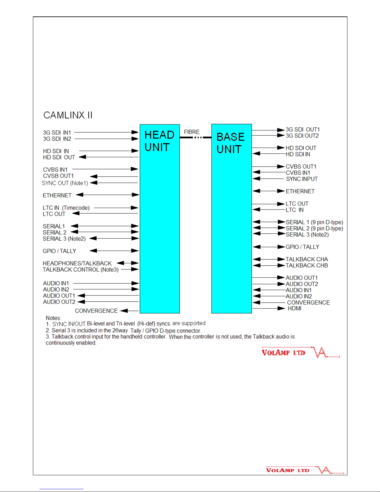
1.1. Camlinx II : Block Diagram
age 6 of 30

Document No. : UserManual_CII_1
2. Camlinx II Units
2.1. Camlinx II : Base Unit
The base unit is housed in an industry standard 1U / 19” rack enclosure with a cooling
fan mounted internally on the right hand side.
age 7 of 30

Document No. : UserManual_CII_1
2.2. Camlinx II : Head Unit
age 8 of 30

Document No. : UserManual_CII_1
2.3. Dimensions and Weights
Dimensions Width x Depth x Height (mm) Weight (kg)
BASE 430 x 270 x 40 ( main 1U enclosure ) 2.5
485 x 270 x 40
(including front panel mounts and connectors)
HEAD 180 x 135 x 70 (main enclosure) 1
185 x 160 x 120
(including fibre pod, connectors, display,
battery plates, tally light)
age 9 of 30
 Loading...