

Page 1
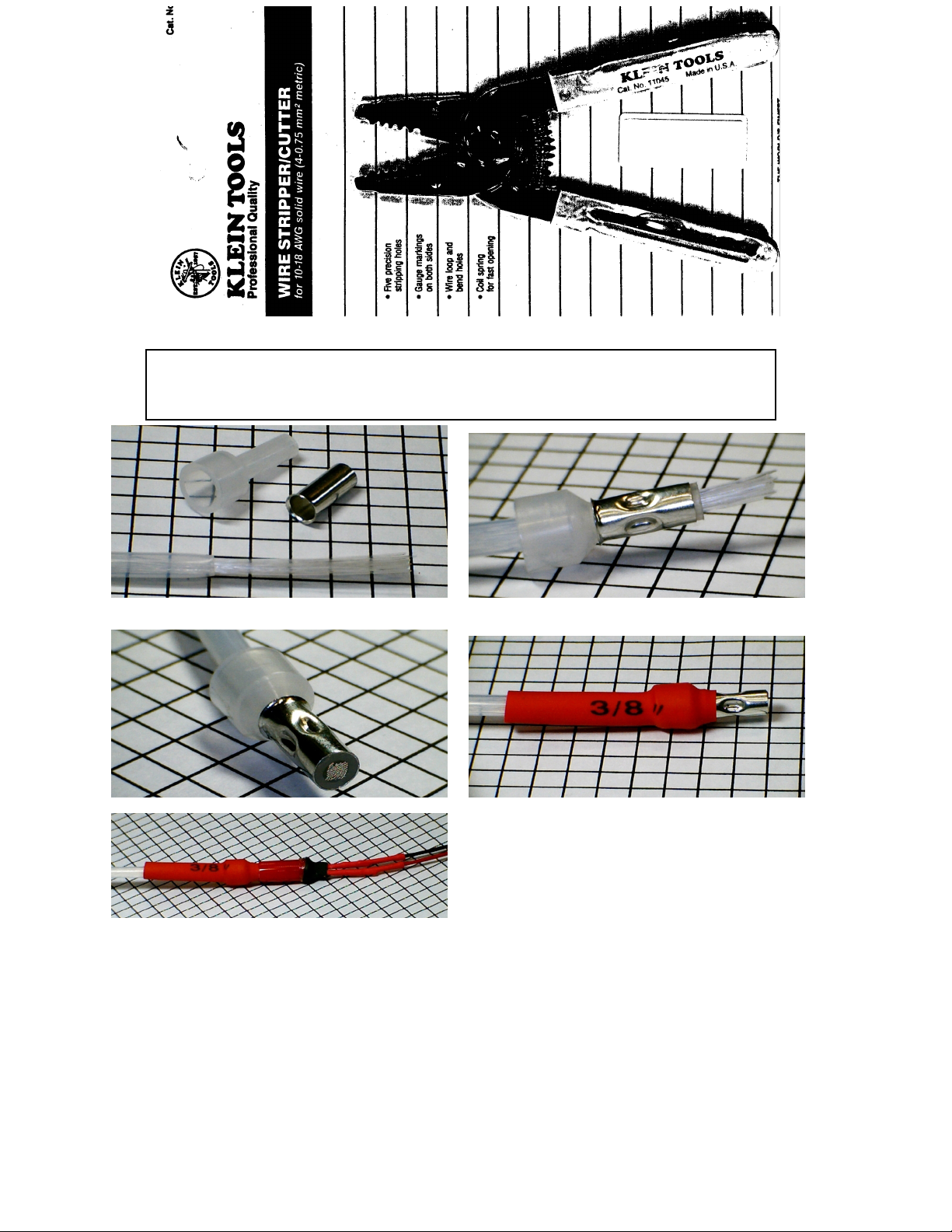
Use a sharp wiring stripping tool like the shown above to cut the Teflon tubing without cutting
the fiber optics. Start the cut using the 10 gauge wire size and then go to the 12 gauge wire size.
Twist the tubing in the cutter to make a cut and pull off the tubing to be removed.
Note-fibers from multiple instruments can go into one ferrule
FL-MDL-001 Rev “B” 6/10/03 4
Page 2
To trim the fiber optic cables to length without cutting the fibers you need to collect the fiber optic cables that will be going
to one LED light source and route them to the light source. Mark the Teflon tubing so that the ends will be even. When
taking the measurement, remember that it is better to be too long than too short. You cannot splice on more fibers if you
cut them short. Once you have marked the Teflon tubing to the desired length, use the Klein Tools wire stripper (or other
very sharp wire stripper) to cut the Teflon tubing. It is best to start the cut of the tubing by placing the tubing in the 10gauge wire size notch and then twist the end of the tubing that is being cut off. Then place the tubing in the 12-gauge wire
size notch and twist the end of the tubing a couple more times. While holding the wire stripper in one hand, you should be
able to pull off the end of the tubing that you wish to remove. By pulling on the tubing end that is being removed rather
than pulling on the wire stripper, you should not cut any of the optical fibers. We suggest that you do a practice cut on the
end of tubing that will be cut off.
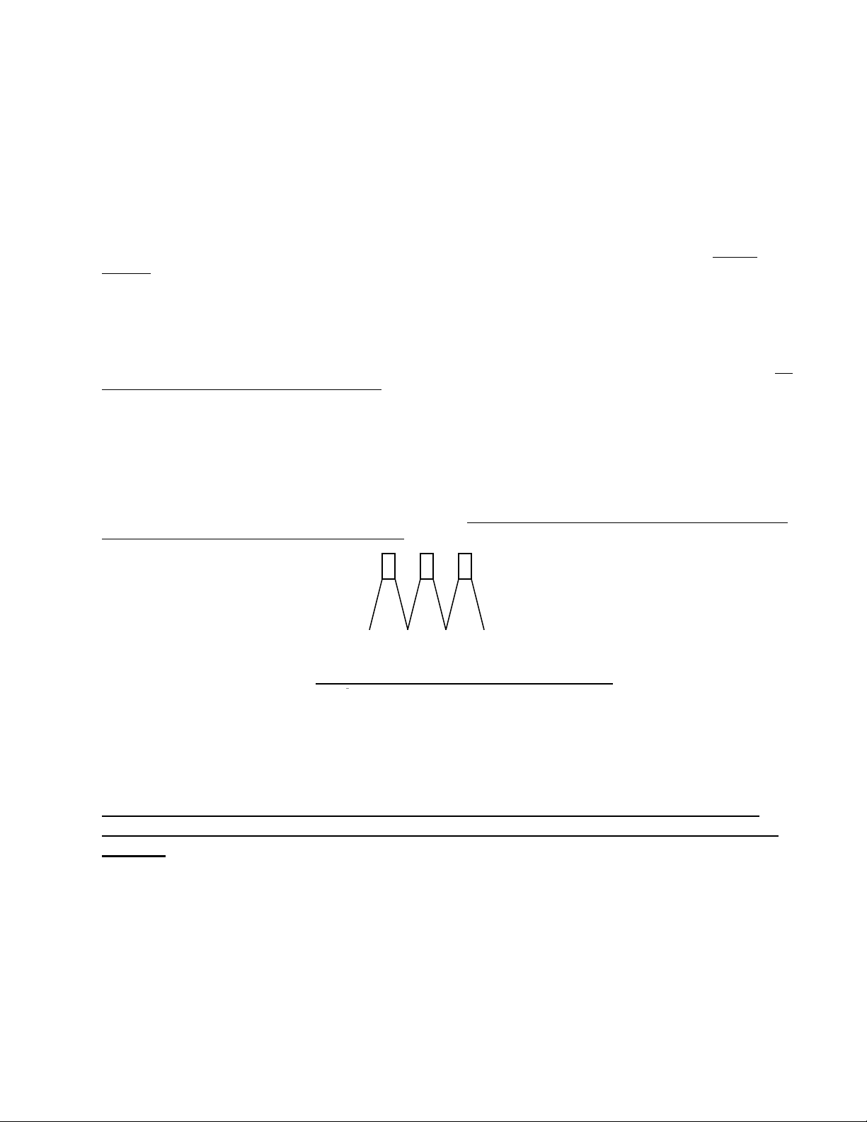
Thread all of the fiber optics through the aluminum crimp connector (and plastic insert). Thread the fibers through the
funnel end of the connector. All of the fibers should be protruding through the connecting ferrule and the Teflon tubing
should be up next to the connector. Using an electrical crimping tool, crimp the aluminum crimp connector near the
shoulder (see picture). Crimp snuggly, but do not use excess force as this can damage the fibers.
2. Trim the fiber optics flush at the ferrule and polish the end with a very fine sand paper. Place heat shrink
tubing over connection.
Use a pocket type finger nail clippers and trim the fibers flush at the tip of the ferrule. Using 300 grit sand (or other very
fine sandpaper) paper briefly polish off the end of the fibers (see picture). Slide the heat shrink tubing so that it covers the
funnel and just slightly onto the aluminum ferrule and the Teflon tubing ends (see pictures). Shrink the tubing using a hot
air gun with minimal heat needed to shrink the tubing. Excessive heat can damage the fibers.
3. The 3 LEDs must be wired in series and the appropriate resistor used that is included with the kit. Review the
wiring diagram that is included on a separate sheet that shows how to wire in the resistor (to positive wire).
CAUTION! The FiberLite LED light sources are extremely bright. Do not look directly at the LEDs.
Wiring in series also provides more even lighting of the LEDs. Even if you do not use all 3 LEDs you must wire them in
series as shown below and tape off the LED not used.
+ - + - + + (positive) wires are red, - (negative) wires are black
Wire in series connecting the red and black wires
After wiring up the LEDs as shown above, press in the aluminum crimp connector as far as possible into the vinyl housing
of the LED. Connect the remaining red wire to a power input and the black wire to a secure ground. LEDs are dimmable
with the use of a solid state dimmer. Superior Panel Technology’s dimmers have been specifically designed to dim LEDs.
A rheostat will not adequately dim LEDs.
NOTE: The optical fibers are flammable (that is why we encase them in the Teflon tubing,
which is very flame resistant). Keep away from sources of heat such as a cigarette lighter and
rheostat.
Tell Us What You Think
We hope that you have found the installation of the FiberLite lighting system neither to difficult nor to time consuming.
If you have any suggestions on how we can improve the lights, the instructions, or anything, please give us a call or drop us
a note so we can improve our product for the next builder/user. Our address and telephone number is listed below.
Superior Panel Technology
Telephone 562-776-9494 email [email protected]
FL-MDL-001 Rev “B” 6/10/03 3
Page 3

FiberLites are designed to sandwich between the instrument and the panel as shown in Figure 2. This will recess the
instrument approximately 3/16”. The bezels come in three different sizes: 2-1/4”, 3-1/8” and 3-1/8” with cutout for knobs.
The bezel with the cutout can be rotated to fit either a left or right knob.
Taking the appropriate bezel, confirm that it fits properly over the instrument. On some instruments the knob may rub
against the bezel and it will be necessary to either modify the cut out space for the knob or to loosen the knob and pull the
knob further out on the shaft so that it clears the bezel.
Installation tip: A brighter spot of light does project out of the end of the fiber optic ribbon. You will not even see this
spot of light if you place the bezel so that the entry port is at the top (12 o’clock position). It will automatically be at the
top when the bezel with the cutout is used for a lower right knob. When used for a lower left hand cutout then the end of
the ribbon will be on the right side. This is totally acceptable, however, if you want it to be at the top then you would need
to modify the bezel with a Dremel tool and add a cut out in the appropriate corner.
IMPORTANT! The glass face of some instruments extends out further to the front. Because of this, some instruments
will require the use of a spacing step washer to prevent the bending of the fiber ribbon (see Fig. 2). Instruments with a
deeper glass set back will not require the spacers. Press the step washers into the holes on the backside of the bezel.
Placing the insert on a table and pressing the bezel down on to the insert is the easiest way to do this. Some instruments
(all attitude indicators) will require an additional washer(s) placed on the collar of the step washer for additional spacing.
Sandwich the bezel between the instrument and the backside of the panel. In most cases, just removing the screws that hold
the instrument to the panel will allow you to move the instrument back far enough to slip the bezel between the instrument
and the panel without undoing the plumbing lines and electrical connections. This of course is your judgment call. If you
only have access to the panel from the bottom, then you will need to remove the screws from a bottom instrument and then
remove the screws from the instrument above it. You should then be able to slide the bezel up in front of the bottom one up
to the top instrument.
Install the instruments back in the panel. The ribbon should be flat and smooth around the bezel. If it is being bent or
crushed, this is an indication that the spacing inserts or additional washers are needed.
Connecting to the FiberLites LED Light Source
You need to connect the fiber-optics to the LED light sources after all of the bezels are mounted. The steps to do this are:
1. Connect the fiber optics from the light bezels to the crimp connector ferrule.
2. Trim the fiber optics flush at the ferrule and place heat shrink tubing over connection.
3. Wire the 3 LEDs in series with the appropriate resistor and press the ferrule into the vinyl housing on the LED.
1. Connecting the fiber optics from the light bezels to the crimp connector ferrule.
Included with the kit is a package of 3 aluminum crimp ferrules. Also included are 3 pairs of plastic ferrule inserts. Each
pair has a different inside diameter (ID). The larger the ID the more fiber optics can be inserted into the ferrule. The goal
is for the fiber optics to be packed snuggly in the ferrule-- so use the one that works that has the smallest ID.
Below you will see the width of fiber optic ribbon that the plastic inserts can accommodate.
Plastic insert #4 will accommodate .5” width of fiber optics
Plastic insert #3 will accommodate .63” width of fiber optics
Plastic insert #2 will accommodate 1.125” width of fiber optics
The larger 3 1/8” instrument has a fiber optic ribbon that is .25” wide. The 2 ¼” instrument light has a ribbon that equates
to .18” width of ribbon.
Using the above information you see that you can combine the fibers from four 3 1/8” instrument lights into ferrule #2
(.25+ .25 +.25 + .25=1”) as ferrule #2 will accommodate up to 1.125” width of ribbon). If you had two 2 ¼” instruments
and one 3 1/8” instruments you would use plastic insert size #3 (.18 +.18 +.25=.61”). If you had just two 3 1/8”
instruments then use plastic ferrule #4 (.25+ .25=.5”). Again, use the smallest ID that will accommodate the fiber optics.
Press the plastic ferrule into the aluminum crimp connector after determining the correct size of insert to use.
FL-MDL-001 Rev “B” 6/10/03 2
Page 4
FiberLites by Superior Panel Technology
FiberLite Installation Instructions-LED light sources
Covered by patent # 5,934,781
1. Tools needed
Klein Tools wire stripper cat. #11045 (available from Home Depot) or similar very sharp wire stripper. Used for cutting
Teflon tubing. See picture of this tool on the fourth page of instructions.
Screwdrivers, hex keys, etc. for removal of instruments and knobs on instruments
Pocket-type fingernail clippers (for snipping the end of the fiber-optics at the ferrule connector)
Hot air gun for shrinking 3/16” heat-shrink tubing
Crimping tool
Longer instrument mounting screws—(we highly recommend the use of Superior Panel Technology’s EZ Nuts)
Dremel tool with small sanding drum
2. FiberLite Bezel Installation
The FiberLite bezels are easily installed between the instruments and the panel once the installer has an understanding of
the system. Before attempting the installation of the FiberLite bezels, lay out the parts supplied with a FiberLite instrument
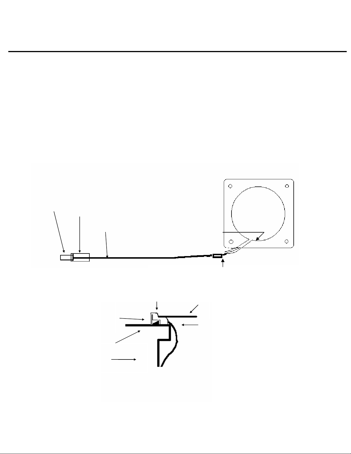
lighting kit. Compare the parts to the drawing below so that you understand how the parts go together.
FIBER CABLE AND BEZEL
Figure 1
NOTE-typically the fiber-optics from 2 or more instruments are feed through
one crimp connector and connected to one LED light source.
Metal crimp connector (with plastic insert)
3/8” heat shrink tubing
Teflon tubing
that encases the fibers
End of entry groove of bezel.
The fiber optic ribbon is
epoxied to the bezel.
Figure 2
CROSS SECTION OF BEZEL
FiberLite ribbon comes applied to the
bezel. Actual ribbon is 1/4” wide on
3-1/8” inst. and 3/16” wide on 2-1/4”
instrument.
FL-MDL-001 Rev “B” 6/10/03 1
Glass instrument face
Instrument body
Aluminum crimp connector on Teflon tubing. Approx. ¼” of fibers
should be exposed between the bezel and the tubing after installation.
Instrument panel
The supplied nylon screw inserts are pushed
into the screw holes on the backside of the
bezel IF needed to prevent bending of the
ribbon during installation.
 Loading...