

Page 1
Installation
& Servicing
Instructions
THESE INSTRUCTIONS
TO BE RETAINED
BY USER
Vokèra is a licensed member of the Benchmark scheme
which aims to improve the standards of installation and
commissioning of domestic hot water systems in the UK.
Zenith Inset
Solar thermal collectors
Page 2

ICV082
ICV08 solar collectors conform to EN 12975 standard.
MODEL CODE
Kit of 2 collectors ICV08 50-37685-13573-9
Kit of 4 collectors ICV08 50-37685-13574-6
CONFORMITY
RANGE
Page 3

ICV08 3
CONTENTS
General safety information and precautions page 4
Description of the solar collector “ 5
Identification “ 5
Design “ 6
Technical specifications “ 7
Accessories “ 7
Water circuit “ 8
Location of probes “ 9
Unpacking the collector page 10
Dimensions and weight “ 11
Handling the collector “ 11
Installation “ 12
Filling the circuit “ 13
Checks “ 14
The following symbols are used in this manual:
b CAUTION! = Indicates actions that require
caution and adequate preparation.
a STOP! = Identifies actions that your MUST NOT
do.
This manual, Code xxxxxxEN - Rev. 0 (04/08) is made
up of 16 pages.
Page 4

ICV084
b
As soon as you open the packaging, check
immediately that the contents are all present and
undamaged. Contact the reseller from whom you
purchased the solar collector if you notice any
problems.
b
This solar collector must be used only for the proper
purpose for which it is designed and made. The
manufacturer declines all responsibility, contractual
or other, for damage to property or injury to persons or
animals caused by improper installation, adjustment,
maintenance or use.
b
The solar collector must be serviced every two
years.
b
Work near uncovered and live electrical wires, with
which it is possible to come into contact, is only
permitted under the following conditions:
- Wires must be free from voltage for the entire
duration of the work.
- Parts remaining live must be covered or accidental
contact prevented.
- The following minimum safety distances must be
respected:
1 m for voltages of up to 1000 Volts
3 m for voltages from 1000 to 11000 Volts
4 m for voltages from 11000 to 22000 Volts
5 m for voltages from 22000 to 38000 Volts
over 5 m if the voltage is not known.
Contact with open, live electrical wires may lead to
electrocution and may even be fatal.
b
Always wear safety goggles when drilling. Always
wear safety shoes, cut-proof protective gloves and
a safety helmet when performing installation work.
b
Before beginning installation work on roofs, install
the necessary fall prevention and fall arrest devices
and ensure that all applicable safety standards are
applied.
Use only tools and materials that conform to the
safety standards that are applicable in the place of
work.
b
Only wear overalls that have a safety harness (with a
suitable safety or fall-arrest belt, ropes or slings, fall
dampers or dissipaters). In the absence of adequate
fall prevention and security devices, failure to use a
proper safety harness may lead to falls from great
heights with serious or even fatal consequences.
b
The use of ladders leaned against walls can lead
to serious falls if the ladder slips, slides of falls.
When using ladders, always ensure that they are
stable, and that suitable ladder stops are present.
If possible secure the ladder with hooks. Make
sure that there are no live electrical wires near the
ladder.
b
Especially when installing the solar collector as part
of a domestic hot water system, follow the orientation
and angle of the roof to ensure that the collector
blends in with the architecture of the building.
b
This instruction manual is an integral part of the solar
collector. It must be kept safe and must ALWAYS
accompany the solar collector, even if it is sold
to another owner or transferred to another user or
to another installation. If you damage or lose this
manual, order a replacement immediately from your
local Technical Assistance Centre.
GENERAL SAFETY INFORMATION AND PRECAUTIONS
Page 5
ICV08 5
DESCRIPTION OF THE SOLAR COLLECTOR
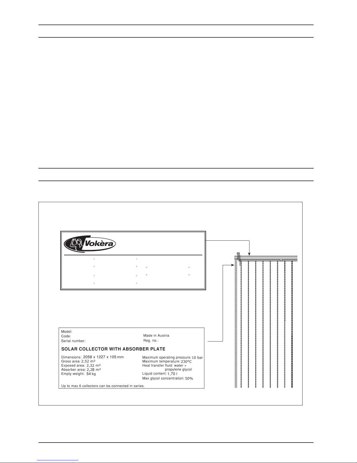
The solar collectors are identified by two plates:
These panel type solar collectors have two water fittings
and consist of a wooden tray covered with a singlepiece copper absorber plate. This has a highly selective
finish obtained by a special vacuum treatment called
"SUN-SELECT", which guarantees excellent collector
performance. The absorber plate is ultrasonically welded
to 12 copper pipes through which the heat transfer fluid
flows. The two main pipe connection manifolds are
also in copper. The top manifold has a central choke
to allow the first 6 pipes to be fed in parallel. After the
heat transfer fluid reaches the bottom manifold, it rises
through the second group of 6 pipes to the top manifold
again. This effectively doubles the thermal length of the
collector.
Each panel is protected by solar, hail-proof, tempered
glass with low iron oxide content and a high energy
transmission factor. The bottom and walls of the tray are
lined with 5.5 cm of rock wool insulation. The temperature
probe is installed in a special copper socket.
These solar collectors are easy to install recessed in the
roof. Provided they are properly installed, they provide
reliable, long lasting and extremely efficient service.
b If these plates or any other means of clearly identifying the product are defaced, removed or lost, proper installation
and servicing may be rendered difficult.
- Data plate
This lists the technical specifications and performance of the product.
- Serial number plate
This bears the collector’s code number, model and serial number.
Serial number
Model
Code
IDENTIFICATION
Page 6

ICV086
Collector
outlet
Collector
return
Collector probe socket
Direction of flow of
heat transfer liquid
DESIGN
Page 7

ICV08 7
TECHNICAL SPECIFICATIONS
ACCESSORIES
1
0,8
0,6
0,4
0,2
0
0 0,02 0,04 0,06 0,08 0,1 0,12
Tm[m2K/W]
*
Total area 2,52 m
2
Exposed area 2,32 m2
Effective absorption area 2,28 m
2
Connections (F) – (F) 1”
Empty weight 54 kg
Liquid content 1,70 l
Recommended flow rate per m2 of panel 30 l/h
Glass type - thickness safety glass with anti-reflective surface - 4 mm
Absorption (α) ~ 0,95 %
Emissions (ε) ~ 0,05 %
Maximum permitted pressure 10 bar
Maximum temperature 230 °C
Maximum number of collectors connectable in series 6 n°
DESCRIPTION
ACCESSORY CODE
kit basic inset colletctor TL 20001441
kit basic cover inset collector TL 20001442
kit additional cover inset collector TL 20001444
kit additional inset collector TL 20001443
The following accessories are available, to be ordered separately.
Efficiency curve
Tested according to EN 12975, referred to a
33.3% water-glycol mix, flow rate of 300 l/h,
and irradiation G = 800W/m
2
.
Tm = (Coll._inlet _temp. + Coll._outlet_
temp.)/2
T*m = (Tm - ambient_temp)/G
Optical
efficiency of
absorber
(ηο)
0,806 3,68 0.0072
Thermal dispersion factor
of absorber
a1
W/(m2K)
a2
W/(m2K2)
Diameter of connection pipes for a specific flow rate of 30 litri/m2h
Total surface area (m
2
) approx. 5 approx. 7,5 approx. 12,5
Diameter of copper pipe (mm) 10-12 15 18
Diameter of steel pipe DN16 DN20
Page 8
ICV088
260
240
220
200
180
160
140
120
100
80
60
40
20
0
0 100 200 300 400 500 600 700 800 900 1000
Pressure drop (mbar)
Flow rate (kg/h)
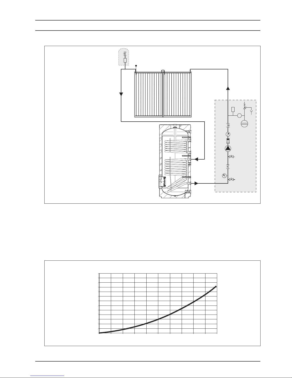
The diagram below illustrates the water connections between solar collectors and a storage heater.
3
11
R
M
°C
M
4
4
4
9
8
11
10
13
14
2
6
12
Water control system
5
7
15
16
17
Pressure drop in solar collectors (*)
1 - Solar collector
2 - Storage heater
3 - Collector probe
4 - Disconnect valves
5 - Non-return valve
6 - Temperature gauge
7 - Vent valve
8 - Safety valve
9 - Pressure gauge
10 - Drain
11 - Expansion vessel
12 - Pump
13 - Flow regulator
14 - Flow meter
15 - Vent cock
16 - Manual bleed valve (accessory)
17 - Coupling joint
(available separately in installation kit)
M - Collector outlet
R - Collector return
b Connect no more than 6 collectors in series.
b If copper pipes are used, joints must be hot
brazed.
b We recommend the use of stainless steel pipes
specially made for solar collectors for the outlet,
return and probe pipes. The probe cable should be
of the shielded type.
b Do not use plastic or multistrate pipes. Operating
temperature can exceed 180°C.
b Pipe lagging must be able to resist high
temperatures (180°C).
(*) Test referred to a 40/60% glycol/water mix and a heat transfer liquid temperature of 50°C.
WATER CIRCUIT
Page 9

ICV08 9
LOCATION OF PROBES
3
11
R
M
°C
M
4
4
4
9
8
11
10
13
14
2
6
12
Water control system
SOLAR
REGULATOR
17
7
15
16
18
5
The temperature sensor must be installed in the nearest socket to the collector outlet. Make sure that the sensor makes
good contact with the socket. Materials (sensor, cables, seals and insulation) used to install the temperature sensor
must be able to withstand high temperatures (up to 250°C).
1 - Solar collector
2 - Storage heater
3 - Collector probe
4 - Disconnect valves
5 - Non-return valve
6 - Temperature gauge
7 - Vent valve
8 - Safety valve
9 - Pressure gauge
10 - Drain
11 - Expansion vessel
12 - Pump
13 - Flow regulator
14 - Flow meter
15 - Vent cock
16 - Manual bleed valve (accessory)
17 - Storage heater bottom probe
18 - Storage heater top probe
M - Collector outlet
R - Collector return
Page 10
ICV0810
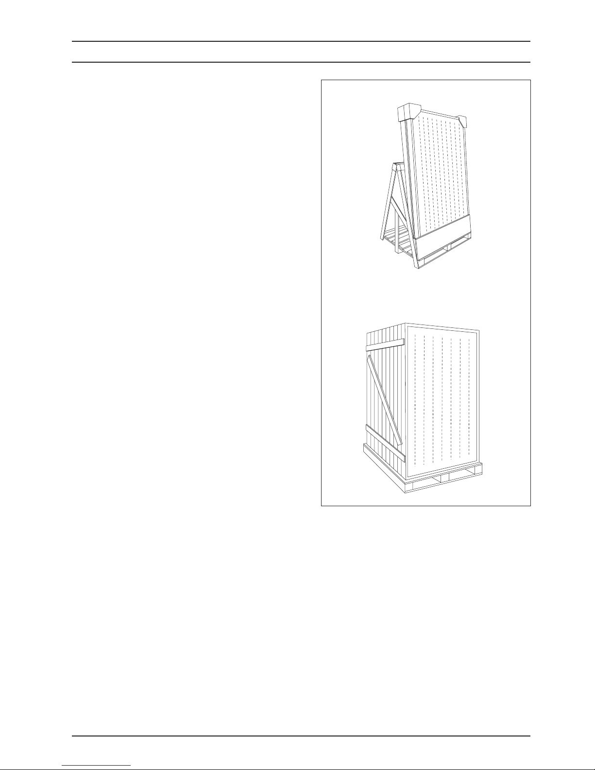
ICV08 solar collectors are packed in various ways
depending on the number of units supplied.
Pallet contents:
- 2, 3 or 10 collectors
- Documentation envelope containing:
- certificate of warranty and label with bar code.
b The instruction manual is an integral part of the
solar connector. Once located, read it thoroughly
and keep it safe.
Pallet with 2 or 3 collectors
Palletised crate containing 10 collectors
UNPACKING THE COLLECTOR
Page 11
ICV08 11
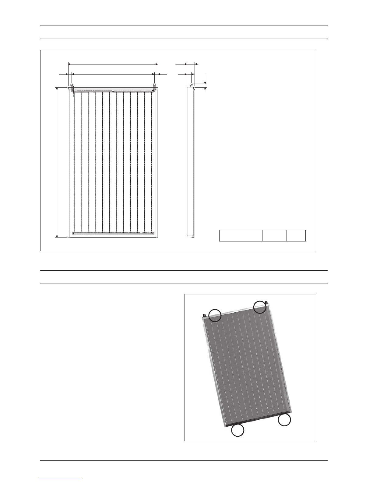
DIMENSIONS AND WEIGHT
HANDLING THE COLLECTOR
Net weight 54 kg
1229
113049 49
2058
105
58
47
Once you have removed the outer packaging, proceed
as follows to unpack and handle the solar collector:
- Remove the PVC wrapping to free the solar collector
from the pallet.
- Tilt the solar collector slightly and grip it at the four
points shown (A) to lift it.
- Use a hoist or other suitable lifting equipment to hoist
the solar collector on to the roof.
b Wear suitable personal protective equipment and
use suitable safety devices.
a
Do not dispose of the packaging material into
the environment where it can become a potential
hazard. Dispose of the packaging material in
compliance with applicable legislation.
A
A
A
A
Page 12

ICV0812
Assembly
The solar collector must be fitted by specialist personnel.
Use only the assembly material supplied with the solar
collector. The supporting framework and all masonry or
brickwork fixing points must be checked by a person
expert in static loading, and must be suitable for the
nature of the installation site.
Static load
The solar collector must only be installed on roofs or
frames that are strong enough to support its weight. The
strength of the roof or frame must be verified on site by a
person expert in static loading before the solar collector
is installed. During this process, it is important to verify
the suitability of the supporting frame to hold the screw
fasteners that fix the solar collector in place. An expert in
static loading must verify that the entire frame complies
with relevant standards, especially in areas liable to
snow and areas exposed to high winds. Conditions
(gusts of wind, formation of wind vortices, etc.) at the
point where the solar collector is to be installed must be
carefully considered since these can increase the loads
on the supporting structure.
Lightning protection
The metal piping of the solar heating circuit must be
connected to the main potential compensation bar by a
(yellow-green) copper wire (H07 V-U or R) of at least 16
mm2. If a lightning conductor system is already installed,
the solar collectors may be connected to the existing
system. Alternatively, the solar collector piping may be
connected to ground via a ground wire sunk into the
earth. Ground wires must be sunk outside the house.
The ground wire must be connected to the potential
compensation bar through a wire of the same diameter.
Water connections
If flexible pipes are not used to connect the solar
collectors, the piping must be fitted with expansion
joints (U-type expansion joints, flexible hoses) to absorb
thermal expansion. Provided adequate expansion joints
are used, up to 6 solar collectors may be connected
in series. Make sure that the seal rings are correctly
positioned in their seats. When tightening a fitting with
a pipe wrench or spanner, always hold the opposite
fitting steady with a second tool to avoid damaging the
absorber.
b All pipes in the water circuit must be insulated in
conformity to relevant standards.
Lagging and insulation must be protected against
damage by the weather and birds and animals.
Angle of collectors / General
Solar collectors are designed to be installed at angles of
between 20° (minimum) and 65° (maximum).
Make sure that the bleed and vent valves of the collectors
remain open while the collectors are being installed.
Take care to protect all fittings, connections, bleed and
vent valves against dirt and dust etc.
In installations which serve primarily to produce domestic
hot water in the summer, install the collectors facing from
east to west at an angle of between 20 and 60°. The
ideal orientation is southwards, at an angle equal to the
latitude of the location minus 10°.
If the system sustains the greatest thermal load in the
winter (as in systems that combine domestic hot water
production with central heating), install the collectors
facing south (or south-east or south-west) at an angle
greater than 35°. The ideal orientation is southwards, at
an angle equal to the latitude of the location plus 10°.
Flushing and filling
For safety reasons, only fill the system when the sun is
not shining.
In areas liable to frost, fill the circuit with a 40% glycol
solution for solar panels.
b The anti-freeze solution must be mixed with water
prior to filling the system.
b Take care if you flush the system out, because any
trapped water may freeze if the circuit is not filled
immediately with anti-freeze.
GENERAL INSTRUCTIONS
INSTALLATION
Page 13
ICV08 13
FILLING THE CIRCUIT
Bleeding
Bleed the circuit:
- On start-up (after initial filling) (see the figure on page
10).
- Whenever necessary, as in the event of system
malfunctioning.
Make quite sure that all air has been bled out of the
system.
b Risk of burns from hot fluid inside the collectors!
b Only open the vent valve if the temperature of the
fluid in the circuit is below 60°C.
Make sure that the collectors are not hot before
you start bleeding the circuit. Always cover the
solar collectors before bleeding the circuit. Always
perform bleeding in the morning.
Checking the heat transfer liquid
Check the anti-freeze effect and the pH level of the heat
transfer liquid every 2 years.
- Use an instrument like a refractometer or densimeter
to check the anti-freeze effect (which must have a
nominal protection value of approx. -30°C). If the
protection threshold is higher than -26°C, replace the
mix, or add anti-freeze as required.
- Use litmus paper to check the pH (nominal value
approx. 7.5). If the measured value is below 7, change
the mix.
Perform the following steps before starting up the system.
1 - FLUSHING AND SEAL TESTING THE SYSTEM
If copper piping has been used and joints have been hot brazed, flush out the system to remove any brazing residues.
Seal test the system after you have flushed it out.
b Fill the solar collector with glycol/water mix immediately after flushing it out, because flushing water may remain
trapped in the circuit (with a consequent risk of freezing).
2 - PREMIXING WATER + GLYCOL
Glycol anti-freeze is supplied separately in standard
volumes and must be premixed with water in a suitable
container before being used to fill the system. For
example, a mix of 40% glycol and 60% water provides
anti-freeze protection down to a temperature of -21°C.
b The propylene glycol supplied is specially
formulated for solar collector applications and
remains fully efficient throughout the -32 to +180°C
temperature range.
It is also non-toxic, biodegradable and
biocompatible.
b Do NOT part fill the circuit with pure glycol then
add water later.
b Do not use automatic or manual filling systems.
b If the water supply is highly chlorinated, use distilled
water to prepare the glycol/water mix.
Anti-freeze
50%
40%
30%
-32°C
-21°C
-13°C
1,045 kg/dm
3
1,037 kg/dm
3
1,029 kg/dm
3
Temperature
Density
Page 14

ICV0814
Manual bleed valve
(accessory)
Anti-freeze mix
Heat exchanger
of solar
Solar collector
Heat
transfer fluid
filling pump
°C
M
A
Water control system
R
M
7
3 - FILLING
1 - Open the non-return valve (A).
2 - Open the air vent at the highest point in the system
(see figure alongside) and keep it open throughout
the filling operation.
3 - Open the vent valve (7).
4 - Pump the heat transfer fluid around the circuit with an
external filling pump until all air bubbles have been
eliminated. Close the manual bleed valve.
5 - Temporarily raise the pressure in the system to 4
bar.
6 - Start up the system for about 20 minutes.
7 - Bleed the system again from step 2 until all the air has
been removed.
8 - Set the pressure in the system to 3 bar.
9 - Close the non-return valve (A) and any open
vent valves to prevent the heat transfer fluid from
evaporating.
b Do not fill the system in bright, sunny conditions or
if the collectors are hot.
b Make sure that you have bled all the air out of the
system, using the water control system vent too.
Heat transfer fluid filling pump (accessory). A manual
bleed valve is not required if this pump is used.
On completion of the installation, perform the checks listed in the table below.
DESCRIPTION OK
Collector circuit
Cold pressure 3 bar
Collector circuit seal test
Safety valve check
Anti-freeze checked to - ___ °C
pH of heat transfer fluid = ____
Collector circuit bled
Flow rate of 30l/h per m
2
checked
Non-return valve functioning
DESCRIPTION OK
Solar collectors
Visual check of collectors
Collectors cleaned if necessary
Visual check of collector fixing points
Visual check of roof impermeability
Visual check of insulation/lagging
CHECKS
Page 15

Page 16

Cod. xxxxxxEN - Rev. 0 (04/08)
Registered address:
Vokèra Ltd
Borderlake House
Unit 7 Riverside Industrial Estate
London Colney
Herts AL2 1HG
enquiries@vokera.co.uk
www.vokera.co.uk
www.vokera.ie
Sales, General Enquires
T 0844 391 099
F 0844 391 0998
Vokèra Ireland
West Court, Callan
Co Kilkenny
T 056 7755057
F 056 7755060
Vokèra Limited reserve the right to change
specification without prior notice
Consumers statutory rights are not affected.
A Riello Group Company.
Company Reg No: 1047779
 Loading...