

Page 1
InstallationInstallation
InstallationInstallation
Installation
& Servicing& Servicing
& Servicing& Servicing
& Servicing
InstructionsInstructions
InstructionsInstructions
Instructions
THESE INSTRUCTIONS
TO BE RETAINED
BY USER
24/28/bi24/28/bi
24/28/bi24/28/bi
24/28/bi
Page 2
Contents
Design principles and operating sequence Page
1.1 Principle components 2
1.2 Mode of operation 2
1.3 Safety devices 2
Technical data Page
2.1 Central heating 3
2.2 Gas pressure 3
2.3 Expansion vessel 3
2.4 Dimensions 3
2.5 Clearances 3
2.6 Connections 3
2.7 Electrical 3
2.8 Flue details 3
2.9 Emissions 3
2.10 Pump duty 4
General requirements Page
3A.1 Related documents 5
3A.2 Location of appliance 5
3A.3 Gas supply 5
3A.4 Flue system 5
3A.5 Air supply 5
3A.6 Water circulation 5
3A.6.1 Pipework 5
3A.6.2 Automatic by-pass 5
3A.6.3 Drain cocks 5
3A.6.4 Air release points 5
3A.6.5 Expans ion vessel 5
3A.6.6 Filling point 5
3A.6.7 Low pressure sealed system 6
3A.6.8 Frequent filling 6
3A.7 Electrical supply 6
3A.8 Mounting on a combustible surface 6
3A.9 Timber framed building 6
3A.10 Inhibitors 6
3A.11 Declaration of conformity 6
Installation Page
4.1 Delivery 7
4.1.2 RAIN application 7
4.1.3 RAIN bi application 7
4.2 Contents (appliance carton) 7
4.3.1 Unpacking 7
4.3.2 Preparation for mounting
the appliance (external application) 7
4.3.3 Important 7
4.4.1 External applications using the enclosure 7
4.4.2 External applications without the enclosure 8
4.5 Fitting the flue 8
4.5.1 Concentric horizontal flue 8
4.5.2 Concentric vertical flue 10
4.5.3 Vokera twin flue application 10
4.6 Connecting the gas and water 10
4.6.1 Gas 10
4.6.2 Flow and return 10
4.6.3 Safety valve 10
4.7 Electrical connections 10
4.8.1 Electrical connection 10
4.8.2 Connecting the mains (230V) input 10
4.7.1 Internal access 11
Commissioning Page
5.1 Gas supply installation 11
5.2 The heating system 11
5.3 Initial filling of the system 11
5.4 Initial flushing 11
5.5 Pre-operation checks 11
5.6 Initial lighting 11
5.7 Checking the burner pressure 11
5.8 Final flushing of the heating system 12
5.8.1 Inhibtors 12
5.9 Setting the boiler operating temperature 12
5.10 Setting the system design pressure 12
5.11 Regulating the central heating system 12
5.12 Final checks 12
5.13 Instructing the user 12
Servicing instructions Page
6.1 General 13
6.2 Routine annual servicing 13
6.3 Replacement of components 13
6.4 Component removal procedure 13
Checks, adjustments and fault finding page
7.1 Checking appliance operation 14
7.2 Appliance mode of operation 14
7.2.1 Selector switch in the OFF position 14
7.2.2 Selector switch in the ON position 14
7.2.3 Appliance functions 14
7.2.4 Heating mode 14
7.2.5 Heating parameters 15
7.3 Checking & adjusting burner pressure 15
7.3.1 Setting the maximum burner pressure 15
7.3.2 Setting the minimum burner pressure 15
7.4 Combustion analysis test 15
7.5 Checking the expansion vessel 16
7.6 External faults 16
7.6.1 Installation faults 16
7.7 Electrical checks 16
7.7.1 Earth continuity test 16
7.7.2 Short circuit check 16
7.7.3 Polarity check 16
7.7.4 Reversed polarity or supply fault 16
7.7.5 Resistance to earth check 17
7.8 Fault finding 17
7.8.1 Replacing the main PCB 17
7.9 Fault codes 17
Wiring diagrams Page
8.1 External wiring 18
8.2 Typical control applications 18
8.3 Room thermostat 18
8.4 Other controls 18
Functional diagram 19
Exploded diagrams Page
Table 1-5 21-24
L.P.G. instructions Page
10.1 Technical data 25
10.2 Converting the appliance gas supply 25
10.3 Gas supply installation 25
10.4 Checking & adjusting burner pressure 25
10.4.1 Setting the maximum burner pressure 25
10.4.2 Setting the minimum burner pressure 25
Page 3
1
24/28/bi 24/28/bi
24/28/bi 24/28/bi
24/28/bi
INTRODUCTION
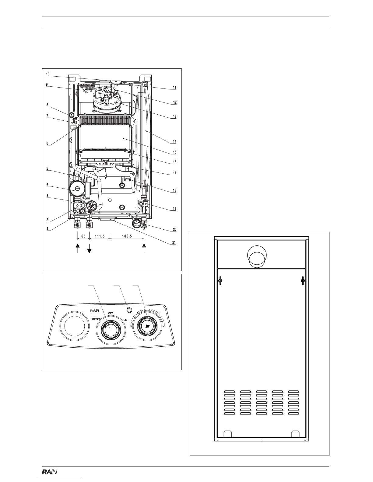
Fig.1/1A General Layout
1 Safety valve
2 Hydraulic manifold
3 Pressure switch
4 Pump
5 Auto air vent (AAV)
6 Main heat exchanger
7 High limit thermostat
8 Primary NTC sensor
9 Differential pressure switch
10 Flue outlet
11 Flue gas analysis test point
12 Silicone pressure tube (-)
13 Fan assembly
14 Expansion vessel
15 Combustion chamber
16 Main burner
17 Electrode
18 Transformer
19 Gas valve
20 Pressure gauge
21 Electrical connection box
22 Main switch
23 Led for working mode
24 Central heating control
The Vokera Rain & Rain bi appliances are central heating boilers, which - by design - incorporates electronic
ignition, circulating pump, expansion vessel, safety valve,
pressure gauge and automatic by-pass.
They are produced as category II2H3+ appliances, suitable for wall mounting applications only. They are provided with a fan powered flue outlet with an annular coaxial combustion air intake that can be rotated - horizontally - through 360 degrees for various horizontal or
vertical applications. The Rain & Rain bi appliances, can
also be used with the Vokera twin flue system.
These appliances are designed for use with a sealed
system only; consequently they are not intended for use
on open vented systems.
The provision of stored hot water is possible by the
addition of an indirect cylinder.
22 23 24
Fig. 1
Fig. 1A
Fig. 1B
Central heating
Gas
Return Flow
Page 4

2
24/28/bi 24/28/bi
24/28/bi 24/28/bi
24/28/bi
SECTION 1 DESIGN PRINCIPLES AND OPERATING SEQUENCE
Fig. 2
1.1 PRINCIPLE COMPONENTS
● A fully integrated electronic control board fea-
turing electronic temperature control, anti-cycle control, pump over-run, self-diagnostic fault
indicator, continuous gas modulation.
● Low-water content copper heat exchanger.
● Electronic ignition with flame supervision.
● Integral pump.
● Fan.
● Expansion vessel.
● Differential air pressure switch.
● Water pressure switch.
● Two-stage gas valve.
● Pressure gauge.
● Safety valve.
1.2 MODE OF OPERATION
When there is a request for heat and/or hot water
via the programmer/time clock and/or any external control, the pump and fan are started, the fan
proves the differential air pressure switch which
in-turn allows an ignition sequence to begin.
Ignition is sensed by the electronic circuitry to
ensure flame stability at the burner. Once successful ignition has been achieved, the electronic
circuitry increases the gas rate to 75% for a
period of 15 minutes. Thereafter, the boiler’s
output will either be increase to maximum or
modulate to suit the set requirement.
When the appliance reaches the desired temperature the burner will shut down and the boiler
will perform a three-minute anti-cycle (timer delay).
When the request for heat and/or hot water has
been satisfied the appliance pump and fan may
continue to operate to dissipate any residual heat
within the appliance.
1.3 SAFETY DEVICES
When the appliance is in use, safe operation is
ensured by:
● A water pressure switch that monitors system
water pressure and will de-activate the pump,
fan and burner should the system water pressure drop below the rated tolerance.
● A high limit thermostat that over-rides the tem-
perature control circuit to prevent or interrupt
the operation of the burner.
● A differential air pressure switch that checks
the operation of the fan and flue thereby allowing safe operation of the burner.
● A safety valve which releases excess pressure
from the primary circuit.
CH
returnCHflow
automatic
by-pass
flue outlet air intake
pressure
switch
main heat
exchanger
CH water drain tap
main
burner
gas valve
pressure
switch
safety
valve
pump
bottom
AAV
expansion
vessel
primary
NTC sensor
fan
Page 5
3
24/28/bi 24/28/bi
24/28/bi 24/28/bi
24/28/bi
SECTION 2 TECHNICAL DATA
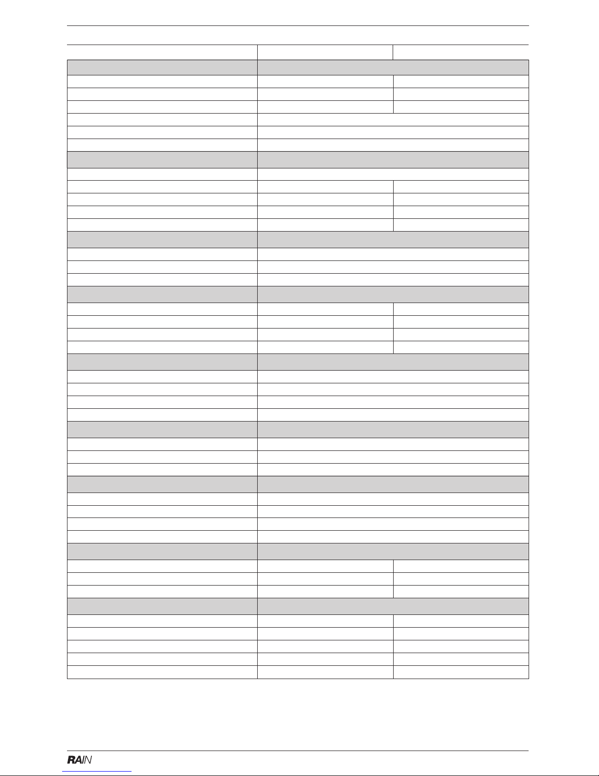
Ref. Condition 15 °C , 1013,25 mbar, dry gas
NOTE: L.P.G. data refer to section 10
2.1 Central heating
Heat input (kW) 26.3 30.5
Heat output (max) 24.0 27.6
Heat output (min) 9.4 10.5
Minimum working pressure 0.5 bar
Maximum working pressure 3.0 bar
Minimum flow rate 350 l/h
2.2 Gas pressures
Inlet pressure G20 20.0 mbar
Maximum burner pressure 10.1 mbar 11.3 mbar
Minimum burner pressure 1.9 mbar 2.25 mbar
Gas rate 2.78 m3/h 3.23 m3/h
Injectors size 12 x 1.35 mm 13 x 1.35 mm
2.3 Expansion vessel
Capacity 8 litres
Maximum system volume 91 litres
Pre-charge pressure 1.0 bar
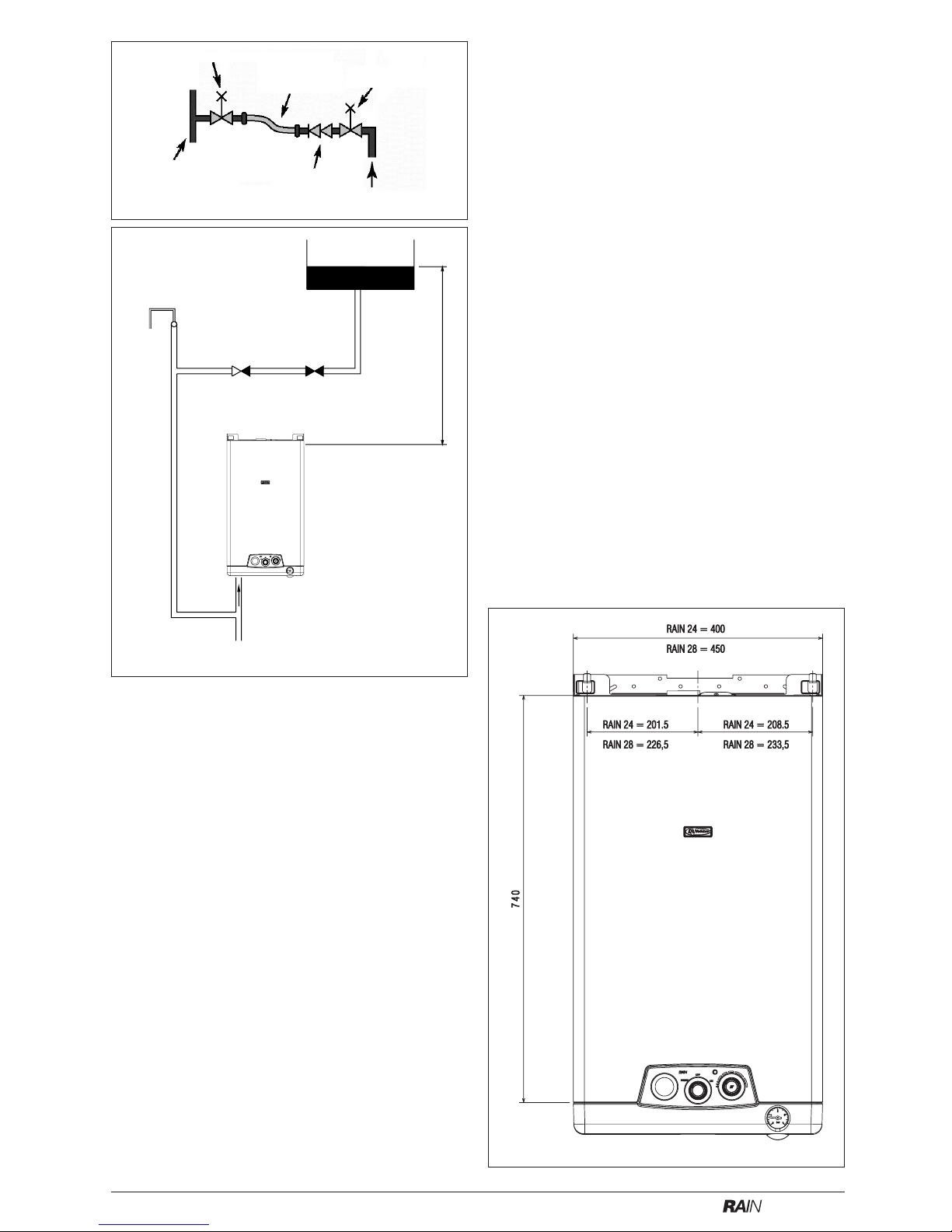
2.4 Dimensions
Height 810 mm (1223 box) 810 mm (1223 box)
Width 450 mm (654 box) 450 mm (654 box)
Depth 250 mm (257box) 250 mm (257box)
Dry weight 35 kg - 31 kg 35 kg - 31 kg
2.5 Clearances
Sides 12 mm
Top 150 mm from casing or 25 mm above flue elbow, whichever is applicable
Bottom 150 mm
Front 600 mm
2.6 Connections
Flow & return 22 mm (compression)
Gas 15 mm (compression)
Safety valve 15 mm copper
2.7 Electrical
Voltage 230V/~ 50hz
Power consumption 125 W
Internal fuse 2 AL
External fuse 3 A
2.8 Flue details (concentric)
Maximum horizontal flue length (concentric) 1.0 m 1.0 m
Maximum vertical flue length (concentric) 1.0 m 1.0 m
Maximum twin flue length (horizontal ir vertical) 20m/20m + terminal 14,5m/14,5m + terminal
2.9 Emissions
NOx (max-min) PPM 140 - 110 140 - 110
CO (max-min) PPM 100 - 130 80 - 150
CO2 (max-min) % 6.95 - 2.60 6.80 - 2.60
CO/CO2 ratio (max) 0.0014 to 1 0.0011 to 1
CO/CO
2
ratio (min) 0.005 to 1 0.0057 to 1
24-24 bi24-24 bi
24-24 bi24-24 bi
24-24 bi
28-28 bi28-28 bi
28-28 bi28-28 bi
28-28 bi
Page 6
4
24/28/bi 24/28/bi
24/28/bi 24/28/bi
24/28/bi
2.10 PUMP DUTY
Fig. 3 shows the flow-rate available - after
allowing for pressure loss through the appliance - against system pressure loss. When
using this graph apply only the pressure loss
of the system. The graph is based on a 20 ºC
temperature differential.
Fig. 4
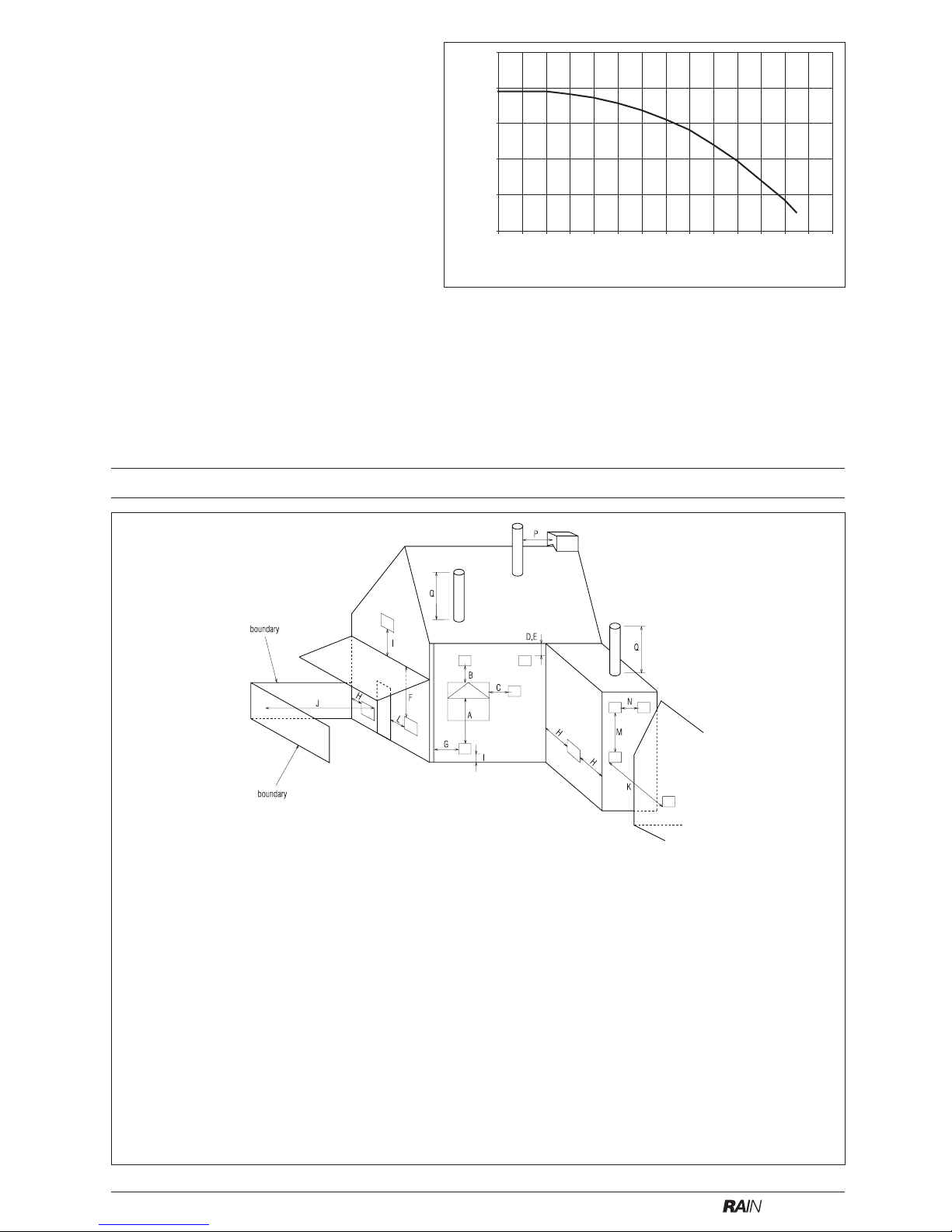
SECTION 3 GENERAL REQUIREMENTS
Key Location Minimum distance
A Below an opening (window, air-brick, etc.) 300 mm
B Above an opening (window, air-brick, etc.) 300 mm
C To the side of an opening (window, air-brick, etc.) 300 mm
D Below gutter, drain-pipe, etc. 75 mm
E Below eaves 200 mm
F Below balcony, car-port roof, etc. 200 mm
G To the side of a soil/drain-pipe, etc. 150 mm
H From internal/external corner or boundary 300 mm
I Above ground, roof, or balcony level 300 mm
J From a surface or boundary facing the terminal 600 mm
K From a terminal facing a terminal 1200 mm
L From an opening in the car-port into the building 1200 mm
M Vertically from a terminal on the same wall 1500 mm
N Horizontally from a terminal on the same wall 300 mm
P From a structure to the side of the vertical terminal 300 mm
Q From the top of the vertical terminal to the roof flashing As determined by the fixed collar
of the vertical terminal
Fig. 3
Water pressure (mbar)
Litres Per Hour (x100)
100
200
300
400
500
600
0 100 200 300 400 500 600 700 800 900 1000 1100 1200 1300 1400
Page 7

5
24/28/bi 24/28/bi
24/28/bi 24/28/bi
24/28/bi
This appliance must be installed by a competent
person in accordance with and defined by, the
Standard Specification (Domestic Gas Installations) Declaration (I.S. 813).
3A.1 RELATED DOCUMENTS
The installation of this boiler must be in accordance with the relevant requirements of the local
building regulations, the current ETCI National
Rules for Electrical Installations, and the bylaws
of the local water undertaking.
It should be in accordance also with any relevant
requirements of the local and/or district authority.
3A.2 LOCATION OF APPLIANCE
The appliance may be installed in any room or
internal space, although particular attention is
drawn to the requirements of the current ETCI
National Rules for Electrical Installations, and I.S.
813, Annex K.
When an appliance is installed in a room or internal space containing a bath or shower, the
appliance or any control pertaining to it must not
be within reach of a person using the bath or
shower. The location chosen for the appliance
must permit the provision of a safe and satisfactory flue and termination. The location must also
permit an adequate air supply for combustion purposes and an adequate space for servicing and
air circulation around the appliance. Where the
installation of the appliance will be in an unusual
location special procedures may be necessary,
refer to I.S. 813 for detailed guidance on this
aspect. A compartment used to enclose the
appliance must be designed and constructed
specifically for this purpose. An existing
compartment/cupboard may be utilised provided
that it is modified to suit.
The appliance can be installed external to a property or dwelling provide the installation has been
carried out in accordance with these instructions
and the provisions of I.S. 813.
3A.3 GAS SUPPLY
The gas meter - as supplied by the gas supplier
- must be checked to ensure that it is of adequate
size to deal with the maximum rated input of all
the appliances that it serves. Installation pipes
must be fitted in accordance with I.S. 813. Pipe
work from the meter to the appliance must be of
adequate size. Pipes of a smaller size than the
appliance gas inlet connection must not be used.
The installation must be tested for soundness in
accordance with I.S. 813. If the gas supply serves
more than one appliance, it must be ensured that
an adequate supply is maintained to each appliance when they are in use at the same time.
3A.4 FLUE SYSTEM
The terminal should be located where the dispersal of combustion products is not impeded and
with due regard for the damage and discoloration
that may occur to building products located nearby.
The terminal must not be located in a place where
it is likely to cause a nuisance (see I.S. 813). In
cold and/or humid weather, water vapour may
condense on leaving the terminal; the effect of
such pluming must be considered. If installed
less than 2m above a pavement or platform to
which people have access (including balconies or
flat roofs) the terminal must be protected by a
guard of durable material. The guard must be
fitted centrally over the terminal. Refer to I.S.
813, when the terminal is 0.5 metres (or less)
below plastic guttering or 1 metre (or less) below
painted eaves.
3A.5 AIR SUPPLY
The following notes are intended for general
guidance only.
This appliance is a fan-flued boiler, approved for
use with certain Type ‘B’ and Type ‘C’ applications. Consequently it may require a permanent
air vent for combustion air supply.
Guidance on the requirements for combustion air
and instructions for Type B22 applications can be
found in Section 4.
3A.6 WATER CIRCULATION
Specific recommendations are given in I.S. 813.
The following notes are for general guidance only.
3A.6.1 PIPEWORK
It is recommended that copper tubing be used in
conjunction with soldered capillary joints.
Where possible pipes should have a gradient to
ensure air is carried naturally to air release points
and that water flows naturally to drain cocks.
Except where providing useful heat, pipes should
be insulated to avoid heat loss and in particular to
avoid the possibility of freezing. Particular attention should be paid to pipes passing through
ventilated areas such as under floors, loft space,
and void areas.
3A.6.2 AUTOMATIC BY-PASS
The appliance has a built-in automatic by-pass.
However it may be necessary to fit an external
bypass should the design of the heating system
require such. In any case, the design of the
system should be such that it prevents boiler
‘cycling’.
3A.6.3 DRAIN COCKS
These must be located in accessible positions to
facilitate draining of the appliance and all water
pipes connected to the appliance.
3A.6.4 AIR RELEASE POINTS
These must be positioned at the highest points in
the system where air is likely to be trapped. They
should be used to expel trapped air and allow
complete filling of the system.
3A.6.5 EXPANSION VESSEL
The appliance has an integral expansion vessel
to accommodate the increased volume of water
when the system is heated. It can accept up to 8
litres of expansion from within the system, generally this is sufficient, however if the system has an
unusually high water content, it may be necessary to provide additional expansion capacity
(see 6.19).
3A.6.6 FILLING POINT
An approved method for initial filling of the system
and replacing water lost during servicing etc. is
required (see fig. 5). This method of filling must
comply with local water regulations and/or I.S.
813.
Page 8
6
24/28/bi 24/28/bi
24/28/bi 24/28/bi
24/28/bi
3A.6.7 LOW PRESSURE SEALED SYSTEM
An alternative method of filling the system would
be from an independent make-up vessel or tank
mounted in a position at least 1-metre above the
highest point in the system and at least 5-metres
above the boiler (see fig. 5A).
The cold feed from the make-up vessel or tank
must be fitted with an approved non-return valve
and stopcock for isolation purposes. The feed
pipe should be connected to the return pipe as
close to the boiler as possible.
3A.6.8 FREQUENT FILLING
Frequent filling or venting of the system may be
indicative of a leak. Care should be taken during
the installation of the appliance to ensure all
aspects of the system are capable of withstanding pressures up to at least 3 bar.
3A.7 ELECTRICAL SUPPLY
The appliance is supplied for operation on 230V @
50Hz electrical supply; it must be protected with a
3-amp fuse. The method of connection to the
mains electricity supply must allow for complete
isolation from the supply. The preferred method is
by using a double-pole switch with a contact separation of at least 3mm. The switch must only supply
the appliance and its corresponding controls, i.e.
time clock, room thermostat, etc.
3A.8 MOUNTING ON A COMBUSTIBLE SURFACE
If the appliance is to be fitted on a wall of
combustible material, a sheet of fireproof material must protect the wall.
3A.9 TIMBER FRAMED BUILDINGS
If the appliance is to be fitted in a timber framed
building, it should be fitted in accordance with I.S.
813 and local Building Regulations.
The Institute of Gas Engineers publication (IGE/
UP/7) ‘Guide for Gas Installations in Timber
Frame Buildings’ gives specific advice on this
type of installation.
3A.10 INHIBITORS
Vokera recommend that an inhibitor - suitable for
use with copper heat exchangers - is used to
protect the boiler and system from the effects of
corrosion and/or electrolytic action. The inhibitor
must be administered in strict accordance with
the manufacturers instructions*.
*Water treatment of the complete heating system
- including the boiler - should be carried out in
accordance with I.S. 813 and the Domestic Water
Treatment Association’s (DWTA) code of practice.
3A.11 DECLARATION OF CONFORMITY
A Declaration of Conformity (as defined in I.S.
813) must be provided on completion of the installation.
A copy of the declaration must be given to the
responsible person and also to the gas supplier if
required.
Fig. 5a
Make-up vessel
or tank
Automatic
air-vent
Non-return
valve
Stopcock
5.0 metres minimum
Heating
return
Fig. 5
control valve
temporary
connection
control valve
supply pipe
double check
valve
flow/return pipe
Fig. 6
Page 9
7
24/28/bi 24/28/bi
24/28/bi 24/28/bi
24/28/bi
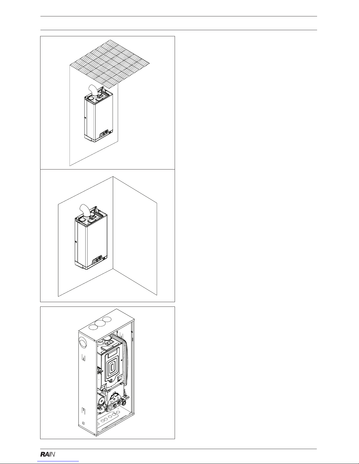
SECTION 4 INSTALLATION
Fig. 7External
installation
Internal
installation
Fig. 7ARain bi Boiler
4.1 DELIVERY
Due to the weight of the appliance it may be
necessary for two people to lift and attach the
appliance to its mounting. The appliance is
contained within a heavy-duty cardboard carton. Lay the carton on the floor with the writing
the correct way up. The appliance enclosure (if
required) is also supplied within a heavy-duty
cardboard carton.
4.1.2 RAIN APPLICATION
The ‘Rain’ can be installed within the property or
external to the property. Although the appliance
is certified IPx5D, if it’s to be installed externally,
it may be necessary to use the rain-cover (not
supplied) and provide reasonable protection from
heavy or persistent rain (see fig. 7). Alternatively,
the appliance enclosure (see figs. 1 & 7A) can be
used (not supplied).
4.1.3 RAIN bi APPLICATION
The ‘Rain bi’ must be installed within the purpose
made enclosure (not supplied) see figs. 1 & 7A.
4.2 CONTENTS (appliance carton)
Contained within the carton is:
● the appliance
● the documentation
● service valves & accessories
● flue restrictors
● appliance template
● appliance wall bracket.
4.3.1 UNPACKING
At the top of the carton pull both sides open - do
not use a knife - unfold the rest of the carton from
around the appliance, carefully remove all protective packaging from the appliance, and lay the
accessories etc. to one side. Protective gloves
should be used to lift the appliance, the appliance
back-frame should be used for lifting points.
4.3.2 PREPARATION FOR MOUNTING THE APPLIANCE (external application)
The appliance and/or the appliance enclosure
should be mounted on a smooth, vertical, noncombustible surface, which must be capable of
supporting the full weight of the appliance and/or
enclosure. Care should be exercised when determining the position of the appliance with respect
to hidden obstructions such as pipes, cables, etc.
When the position of the appliance has been
decided - using the template supplied - carefully
mark the position of the wall-mounting bracket
(see fig. 6) and flue-hole (if applicable).
4.3.3 IMPORTANT
The Rain/Rain bi can be used on various
applications (4.1.2). The following instructions relate to external applications, i.e. external to the property or dwelling.
4.4.1 EXTERNAL APPLICATIONS USING THE ENCLOSURE
Both the Rain and Rain bi boilers can be used with
the enclosure. The Enclosure has been designed
to be recessed into an external wall or surface to
give a flush finish. It can however, be mounted
onto an external wall if required.
Page 10

8
24/28/bi 24/28/bi
24/28/bi 24/28/bi
24/28/bi
Should this application be preferred, it’s recommended that any openings on the top of the
enclosure are sealed with a suitable silicone sealant in order to minimise the ingress or rainwater.
The use of the enclosure allows the installation
pipework to be installed prior to the appliance
being installed.
Due to the enclosure being installed external to
the property, the flueing arrangements for the
appliance can be simplified.
PREPARATION
Refer to the enclosure instructions (supplied) for
specific installation instructions and details on the
required size of opening.
The enclosure is supplied with ‘knock-out’ panels
that allow the appliance flue outlet to routed to the
left, right, or vertically.
In addition, the flue can be routed through the
front of the enclosure.
The route and termination of the flue outlet must
be considered prior to the installation of the
enclosure.
Refer to the relevant sections within this installation booklet and the enclosure instructions for
guidance, and Install the pipework and electrical
supply prior to the fixing of the enclosure. Additionally, if the flue system is to be routed within
the fabric of the property, then it’s advisable to
carry this out before fitting the enclosure.
At this point it will be necessary to remove the
‘knock-out’ panels that are specific to the route
of the flue system and pipework.
FIXING
Secure the enclosure to the wall using the relevant fixing points, taking care to ensure that it is
level and corresponds to the pre-installed
pipework and/or flue system.
Alternatively the enclosure can be secured to an
external wall by modifying the rear panel to
accept fixing screws or bolts.
MOUNTING THE APPLIANCE
Mount the appliance onto the enclosure as indicated in the enclosure instructions.
4.4.2 EXTERNAL APPLICATIONS WITHOUT THE
ENCLOSURE
The Rain boiler can be installed without the
requirement of an enclosure providing that some
form of protection is used to minimise the risk of
water penetration into the appliance (see 4.1.2).
NOTE
The Rain bi must always be installed within
an enclosure.
PREPARATION
Using the template and details at figure 6 as a
guide, secure the appliance wall bracket to the
external wall and mount the appliance to the wall
bracket.
NOTE
The fixing holes for the wall-mounting bracket
should be drilled and plugged, and an appropriate
type and quantity of fixing should be used to
ensure that the bracket is mounted securely.
4.5 FITTING THE FLUE
The Vokera Uni-flue (concentric) system and the
80mm + 80mm parallel (twin) flue system can be
used with the appliance enclosure, whilst the
standard 60/100mm Uni-flue horizontal terminals
can be used on external installations where the
enclosure has not been installed.
In addition the B22 kit can be used on those enclosure
applications that require a simple flue arrangement.
The B22 kit allows air to be taken from the ventilated
enclosure, directly into the appliance and eliminates
the need for an air inlet pipe.
The flue pipe/system can reach temperatures in
excess of 150 °C, and therefore must be insulated or protected to eliminate the risk of injury or
damage to property.
You must ensure that the entire flue system is
properly supported and connected.
FLUE RESTRICTOR RING
To ensure maximum efficiency and correct operation of the appliance, it may be necessary to
fit one of the supplied flue restrictor rings (see fig.
10, item ‘A’) to the appliance flue outlet (see
tables below).
4.5.1 CONCENTRIC HORIZONTAL FLUE
(For concentric vertical flue, see section 4.5.2).
(For twin flue applications, see section 4.5.3).
For internal applications, this appliance must
only be used with the standard 60/100mm
Uni-flue concentric flue system or the Vokera
parallel (twin) system.
NOTE
These instructions relate only to the standard 60/
100mm concentric flue terminals (2359029 &
2359119).
The appliance flue outlet elbow can be rotated
through 360º on its vertical axis. In addition the
flue may be extended from the outlet elbow in the
horizontal plane (see 2.9).
The concentric flue pipe should have a fall from
the boiler, to eliminate the possibility of rainwater
entering the appliance via the flue.
Total flue length Restrictor required
Less than 1 metre 42mm diameter
Less than 2 metres 44mm diameter
Less than 3 metres 46mm diameter
Less than 4.25 metres Not required
24
Total flue length Restrictor required
Less than 0.75 metre 45mm diameter
Less than 1.70 metres 47mm diameter
Less than 2.70 metres 49mm diameter
Less than 3.40 metres Not required
28
Part No. Description Min-Max Length
2359029 Standard flue kit 833mm (dimension ‘X’)
2359119 Telescopic flue kit N/A
Horizontal flue terminals and accessories
Page 11

9
24/28/bi 24/28/bi
24/28/bi 24/28/bi
24/28/bi
4.5.1.1 FITTING THE HORIZONTAL FLUE KIT (enclosure applications)
Determine the route of the flue pipe and carefully
measure the distance from the centre of the
appliance flue outlet to the outside face of the
enclosure (dimension ‘X’ see fig. 7). Ensure the
inner (60mm) pipe is fully inserted into the outer
(100mm) pipe (when the inner pipe is fully inserted, it stands proud of the outer pipe by
7.5mm). Add 32mm to dimension ‘X’ to give the
overall flue length (dimension ‘Y’).
NOTE
The standard horizontal flue kit (part no. 2359029)
is suitable for a distance (dimension ‘Y’) of up to
865mm.
The telescopic flue kit (part no. 2359119) is
suitable for a distance (dimension ’Y’) of up to
600mm.
Dimension ‘Y’ is measured from the end of the
terminal to the end of the outer (100mm) pipe.
The internal trim should be fitted to the flue pipe
before connection of the 90º bend
If the horizontal flue kit (2359029) requires to be
cut to the correct size (dimension ‘Y’), you must
ensure that the inner (60mm) pipe stands proud
of the outer (100mm) pipe by 7.5mm (see fig. 8).
Ensure any burrs are filed or removed and that
any seals are located properly before assembly.
The telescopic flue terminal should be adjusted to
the appropriate length and then fixed using the
securing screw supplied.
The knock-out panel should now be removed to
allow passage of the flue pipe.
4.5.1.2 STANDARD FLUE KIT (2359029)
Hold the inner (60mm) pipe of the terminal assembly and connect to the push-fit end of the
90º bend (supplied) using a twisting action. Insert the assembled flue through the enclosure
hole. Using the clips & screws supplied, connect
the flue assembly to the boiler, ensuring that the
terminal protrudes past the outside surface of
the enclosure by the correct length (135mm).
4.5.1.3 TELESCOPIC FLUE KIT (2359119)
Connect the 60mm push-fit connection of the flue
bend (supplied) to the telescopic flue assembly
using a twisting action. Insert the assembled flue
through the enclosure hole. Using the clips &
screws supplied, connect the flue assembly to
the boiler, ensuring that the terminal protrudes
past the outside surface of the enclosure by the
correct length (135mm).
Fig. 8
dimension ‘Y’
dimension ‘X’
110
4.5.1.4 EXTERNAL APPLICATIONS WITHOUT THE
ENCLOSURE
Vokera recommend that the B22 kit is used on
Rain boilers that are installed external to the
property or dwelling (see fig 8A & 8B).
● Insert the required flue restrictor ring (L) into the
flue spigot (if not already fitted)
● Insert the exhaust connection manifold onto
the appliance flue outlet (N)
● Using the hole in the exhaust connection mani-
fold as a guide, drill a 3mm hole in the appliance
flue spigot and secure the exhaust manifold
connection to the flue spigot using the screw
provided
● Place the silicone seal (supplied with twin
adapter kit) over the rim of the exhaust connection manifold
● Remove the required blanking plate (‘M’ - lo-
cated to the left and right of the appliance flue
outlet) and - using the same screws - install the
air baffle
● Using the hole in the exhaust connection mani-
fold as a guide, drill a 3mm hole in the appliance
flue spigot and secure the exhaust manifold
connection to the flue spigot using the screw
provided
● Connect the exhaust flue outlet terminal to the
exhaust elbow and secure to the wall with the
wall bracket (supplied)
● Insert the air inlet terminal to the air inlet elbow.
Fig. 8A
Fig. 8B
wall bracket
air inlet
flue exhaust
outlet
Page 12

10
24/28/bi 24/28/bi
24/28/bi 24/28/bi
24/28/bi
4.5.2 CONCENTRIC VERTICAL FLUE
The Rain/Rain bi appliance can be used with the
standard 60/100mm concentric vertical terminal.
For further details on vertical terminations, please
contact the Vokera technical help-line.
4.5.3 VOKERA TWIN FLUE APPLICATION
The Rain/Rain bi appliance can be used with the
Vokera twin flue system. For further details on
this type of application, please contact the Vokera
technical help-line.
4.6 CONNECTING THE GAS AND WATER
The appliance is supplied with an accessories
pack that contains sealing washers and service
valves. The service valves are of the compression type. When connecting pipe work to the
valves, tighten the compression end first then
insert the sealing washers before tightening the
valve to the appliance.
NOTE
It will be necessary to hold the valve with one
spanner whilst tightening with another.
4.6.1 GAS (fig. 9)
The appliance is supplied with a 15mm service
valve, connect a 15mm pipe to the inlet of the
valve and tighten both nuts.
NOTE
It will be necessary to calculate the diameter of
the gas supply pipe to ensure the appliance has
an adequate supply of gas.
4.6.2 FLOW & RETURN (fig. 9)
The appliance is supplied with 22mm service
valves for the flow and return connections, connect a 22mm pipe to the inlet of each valve and
tighten both nuts.
4.6.3 SAFETY VALVE (fig. 9)
Connect the safety valve discharge pipe to the
safety valve outlet and tighten. The discharge
pipe must have a continuous fall away from the
appliance to outside and allow any water to drain
away thereby eliminating the possibility of freezing. The discharge pipe must terminate in a
position where any water - possibly boiling discharges safely without causing damage or
injury, but is still visible.
4.7 ELECTRICAL CONNECTIONS
The electrical supply must be as specified in 3.7/
3.7a. The appliance is supplied, pre-wired with a
1.0 metre length of flex, connect the wires as
follows:
Fig. 9
gas
safety
valve
flow
return
● connect the Brown wire to the L (Live) terminal
of the plug or fused isolator
● connect the Blue wire to the N (Neutral) termi-
nal of the plug or fused isolator
● connect the Green/Yellow wire to the E (Earth)
terminal of the plug or isolator
● ensure the plug or fused isolator is fitted with a
3AMP fuse.
If this method of connection is unsuitable, please
refer to section 8. A qualified electrician should
connect the electrical supply to the appliance. If
controls - external to the appliance - are required,
a competent person must undertake the design
of any external electrical circuits, please refer to
Section 8 for detailed instructions. ANY EXTERNAL CONTROL OR WIRING MUST BE SERVED
FROM THE SAME ISOLATOR AS THAT OF
THE APPLIANCE. The supply cable from the
isolator to the appliance must be 3-core flexible
sized 0.75mm to BS 6500. Wiring to the appliance must be rated for operation in contact with
surfaces up to 90 °C.
4.8.1 ELECTRICAL CONNECTION
The appliance terminal strip is located beneath
the appliance control panel (see fig. 10). Locate
and remove the screw that secures the electrical
connection box cover.
NOTE
The appliance comes with a factory fitted link (terminals 1 & 3) to allow basic operation of the boiler
via the selector switch. If external controls are
required please refer to the wiring diagrams in
section 8 for more detailed information.
4.8.2 CONNECTING THE MAINS (230V) INPUT (see
fig. 10)
Remove the connection box cover as described
in 4.8.1. Pass the cable through the cable anchorage. Connect the supply cable wires (earth,
Electrical
connection box
2A fuse
230V supply
VF room
thermostat
connection
Fig. 10
Page 13

11
24/28/bi 24/28/bi
24/28/bi 24/28/bi
24/28/bi
live and neutral) to their corresponding terminals
on the terminal strip. Ensure that the EARTH wire
is left slightly longer that the others, this will prevent strain on the Earth wire should the cable
become taut.
Do not remove the link Do not remove the link
wire (between terminals 1 & 3) unless additional
external controls are to be fitted (see section 8).
Re-fit the electrical connection cover. The securing screw on the cable anchorage must be tightened before the connection cover is replaced.
Fig. 10A
Fig. 10B
4.9.1 INTERNAL ACCESS (fig. 10A)
To gain internal access to the appliance, it’s necessary to remove the appliance casing (Rain only)
and the control panel securing screw (see fig. 10A).
Locate and remove the 2-screws (A) that secure
the appliance casing (Rain only) and gently ease
and lift away the casing from the appliance.
Locate and remove the control panel securing
screw (see fig. 10B) and push down on clip ‘C’ to
release the control panel.
SECTION 5 COMMISSIONING
5.1 GAS SUPPLY INSTALLATION
Inspect the entire installation including the gas
meter, test for soundness and purge. Refer to I.S.
813 for specific instruction.
5.2 THE HEATING SYSTEM
The appliance contains components that may
become damaged or rendered inoperable by oils
and/or debris that are residual from the installation of the system, consequently it is essential
that the system be flushed in accordance with the
following instructions.
5.3 INITIAL FILLING OF THE SYSTEM
Ensure both flow and return service valves are
open, remove appliance casing as described in
4.8.3, identify the automatic air release valve and
loosen the dust cap by turning the cap anticlockwise one full turn. IMPORTANT, THERE
ARE NO MANUAL AIR RELEASE VALVES LOCATED ON THE APPLIANCE. Ensure all manual
air release valves located on the heating system
are closed. Using the method of filling as described in fig. 5, slowly proceed to fill the system.
As water enters the system the pressure gauge
will begin to rise. Once the gauge has reached 1
BAR close the filling valve and begin venting all
manual air release valves, starting at the lowest
first. It may be necessary to go back and top-up
the pressure until the entire system has been
filled. Inspect the system for water soundness,
rectifying any leaks.
5.4 INITIAL FLUSHING
The whole of the heating system must be flushed
as detailed in 5.8. Open all radiator or heating
valves and the appliance flow & return service
valves. Drain the boiler and system from the
lowest points. Open the drain valve full bore to
remove any installation debris from the boiler
prior to lighting. Refill the boiler and heating
system as described in 5.3.
5.5 PRE-OPERATION CHECKS
Before attempting the initial lighting of the appliance, the following checks must be carried out:
● ensure all gas service valves from the meter to
the appliance are open and the supply pipe has
been properly purged
● ensure the proper electrical checks have been
carried out, (see 7.7) particularly continuity,
polarity, and resistance to earth
● ensure the 3 AMP fuse - supplied with the
appliance - has been fitted
● ensure the system has been filled, vented and
the pressure set to 1 BAR
● ensure the flue system has been fitted properly
and in accordance with the instructions
● ensure all appliance service valves are open.
5.6 INITIAL LIGHTING
Ensure the electrical supply to the appliance is
switched on. Switch the time clock or programmer (if fitted) to an ‘on’ position and ensure all
external controls are also calling for heat. Turn
the mode selector knob to the ‘on’ position (fig. 1).
The appliance will now go through an ignition
sequence as described in 1.2. Should the appliance fail to ignite, refer to 5.5 and/or section 7
(fault-finding).
5.7 CHECKING THE BURNER PRESSURE
Although the burner pressure is factory set, it is
necessary to check it during commissioning.
Page 14

12
24/28/bi 24/28/bi
24/28/bi 24/28/bi
24/28/bi
Isolate the appliance from the electrical supply
and attach a suitable manometer to the gas valve
outlet test nipple (see fig. 11). Light the boiler as
described in 5.6 and compare the reading on the
manometer with the value described in section 2.
If adjustment is required, follow the detailed
instructions in section 7 (7.3).
Once the burner pressure has been checked,
isolate the appliance from the electrical supply,
remove the manometer, and tighten the gas
valve outlet test nipple
5.8 FINAL FLUSHING OF THE HEATING SYSTEM
The system shall be flushed in accordance with
I. S. 813 and the DWTA Code of Practice. If a
cleanser is to be used, it must be suitable for low
water content, copper heat exchangers. It shall
be from a reputable manufacturer and shall be
administered in strict accordance with the manufacturing instructions.
5.8.1 INHIBITORS
See section 3A.9.
5.9 SETTING THE BOILER OPERATING TEMPERATURE
The flow outlet temperature can be adjusted
between 40 ºC - 80 ºC via the thermostat knob
(see fig.1).
5.10 SETTING THE SYSTEM DESIGN PRESSURE
The design pressure should be a minimum of 1
BAR and a maximum of 1.5 BAR.
The actual reading should ideally be 1BAR plus
the equivalent height in metres (0.1 BAR = 1
metre) to the highest point in the system above
the base of the appliance (up to the maximum of
1.5 BAR total).
N.B. The safety valve is set to lift at 3 BAR/30
metres/45 psig.
To lower the system pressure to the required
value, pull lever on head of safety valve to release
water until the required figure registers on the
pressure gauge (see fig. 1).
5.11 REGULATING THE CENTRAL HEATING SYSTEM
Fully open all radiator and circuit valves and run
the appliance for both heating and hot water until
heated water is circulating. If conditions are warm
remove any thermostatic heads. Adjust radiator
return valves and any branch circuit return valves
until the individual return temperatures are correct and are approximately equal.
5.12 FINAL CHECKS
● ENSURE ALL TEST NIPPLES ON THE AP-
PLIANCE GAS VALVE HAVE BEN TIGHTENED AND CHECKED FOR SOUNDNESS.
● ENSURE THE APPLIANCE FLUE SYSTEM
IS FITTED CORRECTLY AND IS PROPERLY
SECURED.
● ENSURE ALL PIPE WORK IS RE-CHECKED
FOR SOUNDNESS.
● RE-FIT APPLIANCE CASING.
● CLOSE AND LOCK ENCLOSURE DOOR.
5.13 INSTRUCTING THE USER
Hand over all documentation supplied with this
appliance - including these instructions - and
explain the importance of keeping them in a safe
place.
Explain to the user how to lock/unlock the enclosure door, how to isolate the appliance from the
gas, water and electricity supplies and the locations of all drain points.
Show the user how to operate the appliance and
its associated controls correctly.
Show the user the location of the filling valve and
how to top-up the system pressure correctly and
show the location of all manual air release points.
Explain to the user how to turn off the appliance
for both long and short periods and advise on the
necessary precautions to prevent frost damage.
Explain to the user that for continued safe and
efficient operation, the appliance must be serviced annually by a competent person.
Fig. 11
Outlet
test nipple
Page 15

13
24/28/bi 24/28/bi
24/28/bi 24/28/bi
24/28/bi
SECTION 6 SERVICING INSTRUCTIONS
6.1 GENERAL
To ensure the continued safe and efficient operation of the appliance, it is recommended that it is
checked and serviced at regular intervals.
The frequency of servicing will depend upon the
particular installation conditions, but in general,
once per year should be adequate.
It is the law that any servicing work is carried out
by competent person such as a Vokera engineer,
an approved service agent or Bord Gais.
The following instructions apply to the appliance
and its controls, but it should be remembered
that the central heating and the domestic hot
water systems will also require attention from time
to time.
6.2 ROUTINE ANNUAL SERVICING
Check the operation of the appliance and ensure
it functions as described in section 7. Compare
the performance of the appliance with its design
specification. The cause of any noticeable deterioration should be identified and rectified without
delay.
Thoroughly inspect the appliance for signs of
damage or deterioration especially the flue system and the electrical apparatus.
Check and adjust - if necessary - all burner
pressure settings (see section 7.3).
Check and adjust - if necessary - the system
design pressure (see section 5.10).
Carry out an analysis of the flue gases (see 7.4)
and visually check the condition of the entire flue
assembly. Compare the results with the appliance design specification. Any deterioration in
performance must be identified and rectified without delay.
Ensure both flue venturis are clean and free from
any debris or obstruction.
Ensure both the burner and heat exchanger are
clean and free from any debris or obstruction.
Inspect all joints for signs of leakage and repair if
necessary.
Refer to the commissioning section and/or replacement of parts section for detailed instruction
if required.
6.3 REPLACEMENT OF COMPONENTS
Although it is anticipated that this appliance will
give years of reliable, trouble free service, the life
span of components will be determined by factors
such as operating conditions and usage. Should
the appliance develop a fault, the fault finding
section will assist in determining which component is malfunctioning.
6.4 COMPONENT REMOVAL PROCEDURE
To remove a component, access to the interior of
the appliance is essential. Isolate the appliance
from the electrical supply and remove the fuse.
And when necessary, close all service valves on
the appliance, remove the appliance casing as
described in section 4.8.3, drain the water content from the appliance via the appliance drain
valve or safety valve. Ensure some water absorbent cloths are available to catch any residual
water that may drip from the appliance or removed component. Undertake a complete commissioning check as detailed in section 5, after
replacing any component. ALWAYS TEST FOR
GAS SOUNDNESS IF ANY GAS CARRYING
COMPONENTS HAVE BEEN REMOVED OR
DISTURBED.
Page 16

14
24/28/bi 24/28/bi
24/28/bi 24/28/bi
24/28/bi
7.1 CHECKING APPLIANCE OPERATION
When carrying out any repairs or servicing to the
appliance, the relevant commissioning procedure must be undertaken to ensure the continued
safe operation of the appliance. Particular attention should be made to ensure gas soundness,
water soundness, and the electrical integrity of
the appliance.
7.2 APPLIANCE MODE OF OPERATION
NOTE
There must be sufficient system water pressure
(min. 0.5 bar) to ensure the water pressure switch
is activated. If there is insufficient system pressure the pump and fan will be prevented from
operating.
7.2.1 SELECTOR SWITCH IN THE ‘OFF’ POSITION
When the selector switch is in the OFF position,
the Green LED status indicator will flash every 6seconds to confirm the appliance is in standby
mode. The appliance will not respond to any
heating requests.
Active functions:
●●
●●
● frost-protection system
●●
●●
● pump anti-block
● fan over-run.
7.2.2 SELECTOR SWITCH IN THE ‘ON’ POSITION
When the selector switch is in the ON position,
the Green LED is illuminated:
● flashing every 6-seconds if no Heat and/or hot
water request is active
● constant during a heat and/or hot water re-
quest.
Active functions:
●●
●●
● frost-protection system
●●
●●
● pump anti-block
●●
●●
● fan/pump over-run.
7.2.3 APPLIANCE FUNCTIONS
●●
●●
● Frost-protection: this function is only active
when there are no requests for heating and/or
hot water. When the temperature of the primary
thermistor drops below 5 °C, the boiler will
operate on minimum power until the temperature of the primary thermistor reaches 35 °C.
Thereafter the pump will over-run for 30-seconds.
●●
●●
● Anti-block cycle: when there has been no
heating or hot water request for 19-hours, the
anti-block cycle is activated and the pump will
be activated for a period of 30-seconds.
●●
●●
● Fan over-run: should the temperature of the
NTC thermistor exceed 78 °C after a heating or
hot water request, the pump and/or fan will run
for a period of 30-seconds.
●●
●●
● SARA function: the SARA function permits
the boiler (when the set-point is within the
SARA range) to automatically adjust (raise) the
flow outlet temperature should the room thermostat contacts remain closed for more that
20-minutes.
SECTION 7 CHECKS, ADJUSTMENTS AND FAULT FINDING
7.2.4 HEATING MODE (fig. 12A)
With the selector switch in the ON position and
the relevant controls (time clock, room thermostat, etc,) are calling for heat, the appliance will
operate and the pump and fan will be active. The
operation of the fan causes the air pressure
switch to deliver a signal voltage to the control
PCB. A slow ignition sequence is enabled,
whereby the current supplied to the gas valve
modulating coil is progressively increased from
minimum to maximum over a period of 8-seconds. During this period the ignition electrode
sparks continuously even if the burner has ignited. Ignition is sensed by the electronic circuitry
to ensure flame stability at the burner. Once
successful ignition has been achieved, the electronic circuitry allows 75% 0f the full gas rate
through the appliance. After 15 minutes the gas
rate is increased to maximum (100%).
NOTE
If the spark/sensing electrode does not sense
ignition the appliance will then go to lockout.
When the set-point has been reached (the position of the heating temperature selector) as measured at the primary thermistor, the appliance will
begin the modulation phase whereby the fan and
gas valve will continuously modulate to maintain
the set-point.
If the temperature continues to rise and exceeds
the set-point by 6oC, the burner will shut down
and the boiler will perform a three-minute anticycle (timer delay).
A new ignition sequence will be enabled when the
3-minute anti-cycle has been performed and the
temperature at the primary thermistor has dropped
6 °C below the set-point.
Fig. 12A
Page 17

15
24/28/bi 24/28/bi
24/28/bi 24/28/bi
24/28/bi
NOTES
The timer delay can be de-activated by the insertion of a ‘jumper’ on the PCB at JP2 (fig.14) or by
isolating the appliance from the electrical supply
for 30 seconds.
When the request for heating and/or hot water
has been satisfied, the appliance pump and fan
may continue to circulate to dissipate any residual heat within the appliance.
NOTE
If the spark/sensing electrode does not sense
ignition the appliance will then go to lockout
7.2.5 HEATING PARAMETERS
When the boiler is operating in the SARA range,
the Green LED flashes rapidly to signify the
SARA function is active.
SARA FUNCTION (fig. 12B)
When the heating temperature selector is set
within the SARA range (SARA sector) the boiler
will automatically raise the heating flow outlet
temperature by 5 °C every 20-minutes that the
room thermostat contacts remain in the closed
position or until the boiler reaches the maximum
operating temperature.
7.3 CHECKING AND ADJUSTING BURNER
PRESSURE (see fig. 13)
Although the burner pressure is factory set, it is
necessary to check it during servicing or if the gas
valve has been removed.
Isolate the appliance from the electrical supply
and attach a suitable manometer to the gas valve
outlet test nipple. Remove the compensator tube.
7.3.1 SETTING THE MAXIMUM BURNER PRESSURE
Light the boiler as described in 5.6 and compare
the reading on the manometer with the value
described in 2.2. If adjustment is required, remove the protective cap from the gas valve
modulating coil assembly and turn the outer
(10mm) nut clockwise to increase, or counterclockwise to decrease the burner pressure.
NOTE
You should ensure that all radiators or heat
emitters are fully open during the above procedure. This will ensure that the output of the boiler
(burner pressure) is not compromised due to a
high flow temperature. It may be necessary to fit
a jumper tag to the main PCB (JP2) in order to
cancel the timing function for the 75% output at
start up (see fig. 14).
7.3.2 SETTING THE MIMIMUM BURNER PRESSURE
Once the maximum burner pressure has been
checked and/or adjusted, remove one of the grey
wires from the modulating coil. Compare the
reading on the manometer with the value described in 2.2. If adjustment is required, turn the
inner (red) cross-head screw clockwise to increase, or counter-clockwise to decrease the
burner pressure, whilst ensuring that the outer
(10mm) nut does not move. When checking and/
or adjustment has been completed, isolate the
appliance from the electrical supply, replace the
protective cap, refit the compensator tube, refit
the grey wire to the modulating coil, remove the
manometer, and tighten the outlet test nipple.
IMPORTANT, A GAS SOUNDNESS CHECK
MUST BE CARRIED OUT.
7.4 COMBUSTION ANALYSIS TEST
A combustion analysis check can easily be carried out on the appliance via the test points
located on the top of the appliance, however you
must check that the burner pressures are set
correctly (see section 7.3).
● Insert the flue gas analyser probe into the right
hand test point (see fig. 15).
Fig. 12B
RANGE MINIMUM MAXIMUM
Temperature (°C) 40 80
1
ST
sector 40 55
SARA sector 55 65
3
RD
sector 65 80
Fig. 13
Outlet
test nipple
Modulating coil
connections
Protective cap
Compensator
tube
Outer nut
(maximum)
Inner screw
(minimum)
Fig. 14
Page 18

16
24/28/bi 24/28/bi
24/28/bi 24/28/bi
24/28/bi
Symptom Possible causes
No ignition Check external wiring
Check external controls
No hot water Check external controls
No central heating Check external controls
Frequency Faults/Status
On every 6-secs At stand-by with no faults
Flashing 8-times a second SARA function active
On every 0.5-secs Temporary fault, e.g.:
●●
●●
● APS fault
●●
●●
● low water pressure
Solid Active heating/hot water request
GREEN LED
Frequency Faults/Status
Solid Check JP1
YELLOW LED
Frequency Faults/Status
On every 0.5-secs Final fault, e.g.:
●●
●●
● primary NTC
●●
●●
● water pressure
●●
●●
●
fan/flue problem
●●
●●
● ignition/lockout problem
Solid Limit thermostat
RED LED
● Light the boiler as described in section 5.6.
● You should ensure that all radiators or heat
emitters are fully open during the above procedure. This will ensure that the output of the
boiler (burner pressure) is not compromised
due to a high flow temperature. It may be
necessary to fit a jumper tag to the main PCB
(JP2) in order to cancel the timing function for
the 75% output at start up (see fig. 14).
● Once the combustion analysis test has been
completed, remove the test probe and replace
the protective cap.
7.5 CHECKING THE EXPANSION VESSEL
Carry out the component removal procedure as
described in 6.4. You must ensure that the boiler
is completely drained of waterr.
Using a suitable pressure gauge, remove dust
cap on expansion vessel and check the charge
pressure. The correct charge pressure should be
0.8 BAR ± 0.1 BAR.
If the charge pressure is less, use a suitable
pump to increase the charge.
NOTE
You must ensure the safety valve is in the open
position whilst re-charging takes place. Replace
the dust cap and carry out the relevant commissioning procedure (section 5).
7.6 EXTERNAL FAULTS
Before carrying out any fault-finding or component replacement, ensure the fault is not attributable to any aspect of the installation.
7.6.1 INSTALLATION FAULTS
7.7 ELECTRICAL CHECKS
Any electrical checks must be carried out by a
suitably qualified person.
7.7.1 EARTH CONTINUITY TEST
Isolate the appliance from the electrical supply,
and using a suitable multi-meter carry out a
resistance test. Connect test leads between an
appliance earth point and the earth wire of the
appliance supply cable. The resistance should be
less than 1 OHM. If the resistance is greater than
1 OHM check all earth wires and connectors for
continuity and integrity.
7.7.2 SHORT CIRCUIT CHECK
Isolate the appliance from the electrical supply,
and using a suitable multi-meter, carry out a short
circuit test between the Live & Neutral connections at the appliance terminal strip (fig.16).
Repeat above test on the Live & Earth connections at the appliance terminal strip (fig.16).
NOTE
Should it be found that the fuse has failed but no
fault is indicated, a detailed continuity. Check will
be required to trace the fault. A visual inspection
of components may also assist in locating the
fault.
7.7.3 POLARITY CHECK
With the appliance connected to the electrical
supply and using a suitable multimeter, carry out
the following voltage tests:
● Connect test leads between the Live & Neutral
connections at the appliance terminal strip
(fig.16). The meter should read approximately
230V ac. If so proceed to next stage. If not, see
7.7.4.
● Connect test leads between the Live & Earth
connections at the appliance terminal strip
(fig.16). The meter should read approximately
230V ac. If so proceed to next stage. If not, see
7.7.4.
● Connect test leads between the Neutral &
Earth connections at the appliance terminal
strip (fig.16). The meter should read approximately 0 – 15Vac. If so polarity is correct. If not,
see 7.7.4.
7.7.4 REVERSED POLARITY OR SUPPLY FAULT
Repeat the above tests at the appliance isolator,
if testing reveals correct polarity and/or supply at
the isolator, re-check wiring and connections
between the isolator and the appliance.
Combustion analysis
set point
Fig. 15
Page 19

17
24/28/bi 24/28/bi
24/28/bi 24/28/bi
24/28/bi
If tests on the isolator also reveal reversed polarity or a supply fault, consult the local electricity
supplier for advice.
7.7.5 RESISTANCE TO EARTH CHECK
Isolate the appliance from the electrical supply,
and using a suitable multi-meter carry out a
resistance test. Connect test leads between the
Live & Earth connections at the appliance terminal strip (fig.16). If the meter reads other than
infinity there is a fault that must be isolated, carry
out a detailed continuity check to identify the
location of the fault.
7.8 FAULT FINDING
Before attempting any faultfinding, the electrical
checks as detailed in 7.7 must be carried out.
Isolate the appliance from the electrical supply.
Disconnect any external controls such as room
thermostats etc. from the boiler.
7.8.1 REPLACING THE MAIN PCB
When replacing the main PCB it’s essential
that the potentiometers are set as follows:
● P4 - set at minimum
● P5 - set at maximum.
EFFECT OF JUMPER TAGS FITTED TO THE
MAIN PCB AT:
● JP1 - Rain/Rain bi boiler
● JP2 - cancels anti-cycle function and initial
heating output (75% of maximum at start up)
● JP3 - for LPG boilers only
● JP4 - N/A.
NOTE
Restore the electrical supply to the boiler and turn
the selector switch to the on position. The boiler
should now function as described in section 7.2.
Should the boiler fail to respond, the internal
fuses and connectors should be checked to
ensure integrity and continuity. If the boiler still
fails to respond, refer to the detailed faultfinding
flowcharts overleaf.
IMPORTANT
These series of checks must be carried out
before attempting any fault-finding procedures
on the appliance. On completion of any task that
required the disconnection and re-connection of
any electrical wiring or component, these checks
must be repeated.
7.9 FAULT CODES
When the boiler is in a fault condition, the LED is
displayed in a colour and/or frequency that is
relevant to the fault. To reset the boiler, turn the
mode selector switch to the reset position for 2minutes’ then back to the relevant mode of operation.
If the boiler does not reset, refer to the following
section and the detailed faultfinding flowcharts
overleaf.
Frequency Faults/Status
Solid Check JP1
YELLOW LED
Frequency Faults/Status
On every 0.5-secs Final fault, e.g.:
●●
●●
● primary NTC
●●
●●
●
water pressure
●●
●●
● fan/flue problem
●●
●●
● ignition/lockout problem
Solid Limit thermostat
RED LED
Page 20

18
24/28/bi 24/28/bi
24/28/bi 24/28/bi
24/28/bi
SECTION 8 WIRING DIAGRAMS
8.1 EXTERNAL WIRING
The appliance comes with a factory fitted link (fig.
16) to allow basic operation of the boiler via the
mode selector switch. If external controls are to
be added to the system, they must be connected
to the boiler as shown in the following diagrams.
For advice on controls that are not featured in this
book, please contact Vokera technical on 0870
333 0520.
8.2 TYPICAL CONTROL APPLICATIONS
The appliance can be used with the following
controls:
● external single-channel, voltage-free time clocks
● voltage-free room thermostats
● voltage-free programmable room thermostats.
In addition, the appliance can be used in conjunction with a typical ‘S’-Plan system, please contact
Vokera technical for further detailed instruction.
NOTE
This appliance is not suitable for use with ‘Y’-Plan
systems.
8.3 ROOM THERMOSTAT
Should a room thermostat or external clock be
required, it must be of the ‘voltage-free’ type, and
should be connected to the appliance as shown
in fig. 16A.
8.4 OTHER CONTROLS
Contact the controls manufacturer and/or Vokera
technical department should you require more
specific information on the suitability of a particular control.
Further guidance on the recommended practice
for the installation of external controls, can be
found in CHeSS – HC1/HC2 (www.energyefficiency.gov.uk).
Factory
configuration
Fig. 16
Voltage-free, single-channel
clock or programmable room
thermostat
Fig. 16A
Key
P2 Central heating temperature control
P3 Off/summer/winter selector
R.T. Room thermostat
P.S. Pressure switch
D.P.S. Differential pressure switch
H.L.T. High limit thermostat
H.T. Heat thermistor
P4-P5 Setting trimmer
JP1 C.H. only selector
JP2 Setting timer
JP3 Natural gas or L.P.G. selector
Fuse 2AF External fuse 2AF (on 230V circuit)
F1 (CP04X) Fuse 2AF (on 230 V circuit)
SP/SE. E. Spark/Sense electrode
RL1 Pump relay
RL2 Fan relay
RL4 Ignition relay
LED Led OK (green)
Led alarm (red)
MOD Modulator
F Fan
P Pump
OPE Gas valve solenoids
CP04X Control board
CN1-CN9 Connectors
TRF1 Trasformer
ACF01X Ignition control board
ME External terminal board
Page 21

19
24/28/bi 24/28/bi
24/28/bi 24/28/bi
24/28/bi
FUNCTIONAL DIAGRAM
NOTE: L-N-E CONNECTION IS ADVISABLE
Fig. 17
Page 22

20
24/28/bi 24/28/bi
24/28/bi 24/28/bi
24/28/bi
SECTION 9 EXPLODED DIAGRAMS
POS. DESCRIPTION 24 28 24 bi 28 bi
10 Support 10025348 10025348 10025348 10025348
12 Quick primer pressure gauge 10024664 10024664 10024664 10024664
15 Wiring junctions 01005313 01005313 01005313 01005313
18 Cover 10024677 10024677 10024677 10024677
19 Ignition module 10022174 10022174 10022174 10022174
20 Printed circuit board 10025340 10025340 10025340 10025340
21 Led light guide 10024680 10024680 10024680 10024680
22 Gear wheel 10024682 10024682 10024682 10024682
25 Cover 10024676 10024676 10024676 10024676
26 Front panel 10027710 10027710 10027710 10027710
27 Cover 10024687 10024687 10024687 10024687
31 Case 10024692 10024692 - 44 Cover 10024686 10024686 10024686 10024686
60 Control panel brackets 01005307 01005307 01005307 01005307
64 Frame 10024660 10024660 10024660 10024660
66 Cover 10024694 10024694 - 87 Knob support and gear wheel kit 01005306 01005306 01005306 01005306
90 Tdc 180 bs 1362 3a fuse 3478 3478 3478 3478
104 Front panel protection 10027269 10027269 10027269 10027269
113 Gear wheel 10024681 10024681 10024681 10024681
232 Edge clip 5151 5151 5151 5151
270 Transformer 10021272 10021272 10021272 10021272
300 Wiring harness 10024689 10024689 10024689 10024689
270
10
12
19
20
18
21
25
22
113
26
44
27
66
232
90
31
87
64
15
59
300
104
Page 23

21
24/28/bi 24/28/bi
24/28/bi 24/28/bi
24/28/bi
POS. DESCRIPTION 24 28 24 bi 28 bi
3 Pressure switch 2044 2044 2044 2044
7 Heating by-pass valve 1552 1552 1552 1552
9 Heating distrib. manifold 10021821 10021821 10021821 10021821
22 Safety valve 2907 2907 2907 2907
27 Heating cock 1789 1789 1789 1789
31 Venting plugs kit 01005137 01005137 01005137 01005137
50 Cover 10025591 10025591 - -
63 Pipe 10027841 10027841 - 200 Washer 5023 5023 5023 5023
266 Washer 5237 5237 5237 5237
353 Ogive 1824 1824 - 400 Wiring harness 10027713 10027713 10027713 10027713
266
266
27
27
50
.1
22
9
3
31
7
353
353
200
400
Page 24

22
24/28/bi 24/28/bi
24/28/bi 24/28/bi
24/28/bi
POS. DESCRIPTION 24 28 24 bi 28 bi
1 Expansion vessel 10024662 10024662 10024662 10024662
2 Flexible pipe 10025188 10025188 10025188 10025188
3 Up 15-50 ao pump 10020437 10020437 10020437 10020437
4 Automatic air vent bottle 0439 0439 0439 0439
7 Pipe 10024672 10024672 10024672 10024672
8 Heat exchanger 10023651 10024301 10023651 10024301
9 Pipe 10027709 10027709 10027709 10027709
11 Bracket 1642 1642 1642 1642
12 Washer 2226 2226 2226 2226
28 Pump lock key 9263 9263 9263 9263
201 Washer 5026 5026 5026 5026
288 O-Ring 6898 6898 6898 6898
289 Clip 2223 2223 2223 2223
290 Clip 2165 2165 2165 2165
299 Washer 10022726 10022726 10022726 10022726
417 High limit thermostat 10024710 10024710 10024710 10024710
1
2
201
2
290
28
288
288
7
9
3
12
8
289
299
417
288
289
520
4
12
Page 25

23
24/28/bi 24/28/bi
24/28/bi 24/28/bi
24/28/bi
POS. DESCRIPTION 24 28 24 bi 28 bi
1 Roomsealed chamber 10024669 10024745 10024669 10024745
2 Air box clip 0442 0442 0442 0442
3 Main burner injector manifold 10025271 10024742 10025271 10024742
4 Burner 10025270 10026102 10025270 10026102
5 Spark-sensing electrode 10025985 10025985 10025985 10025985
12 Pipe 10024668 10024668 10024668 10024668
13 Gas valve 10021021 10021021 10021021 10021021
14 Gas valve solenoid 10020838 10020838 10020838 10020838
15 Gas cock 10020897 10020897 10027806 10027806
16 Cover assembly 10024779 10024779 10024779 10024779
18 Glass 10021558 10021558 10021558 10021558
27 Hole cover 10023805 10023805 10023805 10023805
200 Washer 5023 5023 5023 5023
300 Ng conversion kit 01005225 01005225 01005225 01005225
301 Lpg conversion kit 01005297 01005297 01005297 01005297
400 Wiring harness 10025370 10025370 10025370 10025370
200
15
5
18
200
13
12
200
1
27
4
3
27
2
14
16
300
301
400
Page 26

24
24/28/bi 24/28/bi
24/28/bi 24/28/bi
24/28/bi
POS. DESCRIPTION 24 28 24 bi 28 bi
2 Back insulating panel 2230 2230 2230 2230
3 Lateral insulating panel 2231 2231 2231 2231
4 Front insulating panel 2232 2232 2232 2232
10 Fan 10020793 10023907 10020793 10023907
12 Fan connection 10021972 10021972 10021972 10021972
20 Fumes testing connection pipe 10021973 10021973 10021973 10021973
25 Pressure diff. switch 01005272 10023908 01005272 10023908
28 Stop clip 10020626 10020626 10020626 10020626
4
25
12
28
20
10
2
3
3
Page 27

25
24/28/bi 24/28/bi
24/28/bi 24/28/bi
24/28/bi
SECTION 10 L.P.G. INSTRUCTIONS
10.2 GAS SUPPLY
The gas supply must be connected to the appliance by a competent LPG installer and must be
of sufficient size to supply the appliance at its
maximum output.
An existing supply must be checked to ensure
that it is of adequate size to deal with the maximum rated input of this and any other appliances
that it serves.
10.3 GAS SUPPLY INSTALLATION
The entire installation including the meter must
be purged and checked for gas soundness.
10.4 CHECKING AND ADJUSTING BURNER PRESSURE (see fig. 21)
Although the burner pressure is factory set, it is
necessary to check it during servicing or if the gas
valve has been removed.
Isolate the appliance from the electrical supply
and attach a suitable manometer to the gas valve
outlet test nipple. Remove the compensator tube.
10.4.1 SETTING THE MAXIMUM BURNER PRESSURE
Light the boiler as described in 5.6 and compare
the reading on the manometer with the value
described in 10.1. If adjustment is required, remove the protective cap from the gas valve
modulating coil assembly and turn the outer
(10mm) nut clockwise to increase, or counterclockwise to decrease the burner pressure.
NOTE
You should ensure that all radiators or heat emitters are fully open during the above procedure.
This will ensure that the output of the boiler
(burner pressure) is not compromised due to a
high flow temperature.
10.1 TECHNICAL DATA
GAS PRESSURES 24-24 bi 28-28 bi
Inlet gas pressure 37 mbar 37 mbar
Burner pressure maximum 36.00 mbar 36.00 mbar
Burner pressure minimum 7.30 mbar 6.80 mbar
Maximum gas rate 2.04 kg/h 2.37 kg/h
Minimum gas rate 0.87 kg/h 0.99 kg/h
Injectot size (quantity) 12 x 0.77 13 x 0.78
NOx (max - min) PPM 160 - 110 180 - 120
CO (max - min) PPM 80 - 140 70 - 150
CO2 (%) 8.10 - 3.10 7.65 - 2.90
CO/CO
2
ratio (max - min) 0.0009 to 1 - 0.0045 to 1 0.0009 to 1 - 0.0051 to 1
10.4.2 SETTING THE MINIMUM BURNER PRESSURE
Once the maximum burner pressure has been
checked and/or adjusted, remove one of the grey
wires from the modulating coil. Compare the
reading on the manometer with the value described in 10.1. If adjustment is required, turn the
inner (red) cross-head screw clockwise to increase, or counter-clockwise to decrease the
burner pressure, whilst ensuring that the outer
(10mm) nut does not move. When checking and/
or adjustment has been completed, isolate the
appliance from the electrical supply, replace the
protective cap, refit the compensator tube, refit
the grey wire to the modulating coil, remove the
manometer and tighten the outlet test nipple.
IMPORTANT, A GAS SOUNDNESS CHECK
MUST BE CARRIED OUT.
For details of converting boilers to LPG please refer to the instructions supplied with the relevant conversion kit.
Page 28

Cod. 10027715 - 39/05 - Ed. 1
energizing home heating
Vokèra Ltd.
4th Floor, Catherine House, Boundary Way, Hemel Hempstead, Herts, HP2 7RP
Email: enquiries@vokera.co.uk Web: www.vokera.co.uk
Sales, Technical Advice, General Enquiries - Tel: 0870 333 0520 Fax: 01442 281403
After Sales Service - Tel: 0870 333 0220
Vokèra Ireland
West Court, Callan, Co Kilkenny
Tel: 05677 55057 Fax: 05677 55060
Vokèra Ltd. reserve the right to change the specifications without prior notice. Consumers’ statutory rights are not affected.
A Riello Group Company
 Loading...