

Page 1
Installation
& Operating
Instructions
THESE INSTRUCTIONS
TO BE RETAINED
BY USER
OpenTherm
Programmable room thermostat
Page 2
This combined control RFT & OTR (transmitter & receiver) is for use only with the
following Vokera appliances:
• Unica HE
• Linea 28HE*,32HE*,36HE*
• Mynute HE
• Mynute VHE
*
Requires wiring kit
This combined control must not be used or
connected to any other appliance. This
apparatus must only be installed by a
competent person.
This control is comprised of a battery operated transmitter (RFT) and a wired receiver
(OTR); the transmitter can be located within
any heated area* of the dwelling whilst the
receiver must be connected to the boiler**.
* The transmitter can be located up to 25-metres from
the receiver and must be located in an area that is
directly heated by the boiler
**The receiver must be connected to the boiler’s Open-
therm connections (see installation booklet) and be
sited no more than 1-metre from the boiler
These instructions must be read in conjunction with the appliance installation booklet.
Isolate the appliance from the electrical supply and remove the appliance casing. Locate
and remove the PCB cover that contains the
Opentherm terminals.
Remove the cover from the receiver and
using a suitable piece of 2-core flex, connect
the receiver to the Opentherm terminals of
the appliance and refit
the PCB cover and
appliance casing.
NOTE
The receiver can be mounted on a wall adjacent to the appliance.
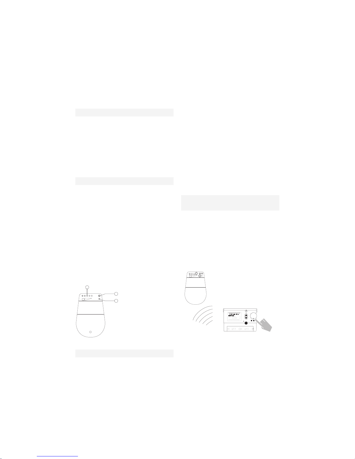
The combined control (transmitter & receiver) are coded and paired during the final
production test; it’s therefore not necessary
to pair the unit at the point of installation or
first-use. However if the transmitter/receiver
has been reset or either component (transmitter/receiver) is to be used with a replacement/different unit, it will be necessary to recode and pair the new combination.
Ensure the transmitter has been set/left in
the coding mode (menu > service > coding
> OK) and press button B on the receiver for
approximately 5-seconds, LED A will light up
briefly. Press ESC to escape from the coding mode.
SPECIFIED USE
WARNING
2.0 PAIRING/CODING OF THE RECEIVER
WITH THE TRANSMITTER
1.0 INSTALLATION OF THE RECEIVER
A
C
B
5
4
3
2
1
A. LED
B. Coding button
C. Field strength indicator
i
ESC
RES
PARTY·ECO
MENU
+
–
OK
3
4 5
6721
Receiver
Transmitter
1
Page 3
To check that the coding is active or has
been successful, go back into the coding
mode for the transmitter (menu > service
> coding), when you press OK the LED A
will light up briefly to confirm that the receiver is now paired with the transmitter.
To check that the receiver is picking up a
signal from the transmitter, enter into the
menu: Menu > Service > Test HF.
A test signal will be sent for a period of 15minutes from the transmitter to the receiver
every 5-seconds. In turn, at least one signal
strength indicator LED should light up; the
strength of signal is indicated by the quantity
of LED’s that are illuminated.
Place the transmitter in a room or location
that enables optimum signalling.
To cancel the signal strength test, press
ESC at any time.
Should it be necessary to cancel or reset the
current coding/pairing of the receiver with a
respective transmitter, press button B for
10-seconds. The LED will illuminate for 3seconds before going out.
The transmitter (RFT) is powered by 2 x AA
batteries and these should last approximately 1.5-years.
The transmitter can be wall-mounted or can
left on a desktop or table-top using the freestanding support (supplied).
Remove the battery compartment cover and
insert 2 x AA batteries within 10-minutes to
ensure any memorised program or setting is
maintained.
The transmitter (RFT) and receiver (OTR)
have been coded and paired with each other
during the final production test at the factory.
However if either of the components have
been reset or is a replacement unit it will be
necessary to code and pair the RFT with the
OTR (see section 2.0)
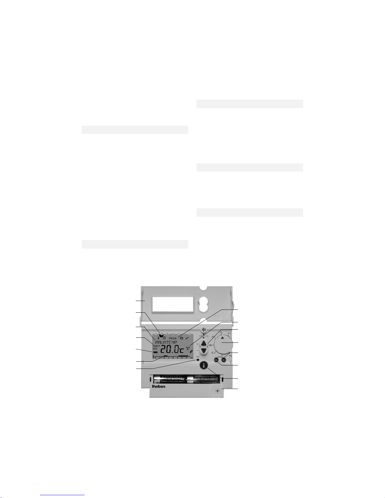
Hinged cover
Display of the day of week
(1 = Monday, 2 = Tuesday etc.)
Multifunctional display, e.g.
“Room temperature 20.0˚C”
Display PARTY- or
ECO program active
Display for batteries to be replaced
Display of the switch phases
RESET button
Icon bar for display of the
programming level (rotary switch
position MENU)
Change buttons
+/–
Rotary switch for program selection
Button OK (confirmation of setting/
selection or programming)
Button ESC (cancellation of programming entries)
Info button for checking the settings
Battery compartement
To open, pull towards the front
Symbol appears during a radio
transmission
2.1 SIGNAL STRENGTH TEST
2.2 CODING RESET
3.0 TRANSMITTER OVERVIEW AND SETUP
3.1 INSERTING/REPLACING BATERIES
3.2 INITIAL SETUP
2
Page 4
Once the batteries have been inserted into
the battery compartment and the OTR has
been connected to the boiler, the transmitter
can be mounted/located and programmed
for use.
The RFT can be mounted on any wall within
the dwelling or can be table/desk located
using the stand provided.
To ensure optimum performance, it’s preferable to carry out a signal strength test (section 2.1) before deciding on a final location.
Ideally, for wall mounted applications, the
unit should be positioned 1.5-metres from
the floor level.
Avoid areas such as near or above fireplaces, televisions, windows, or radiators that
provide artificial room temperature conditions.
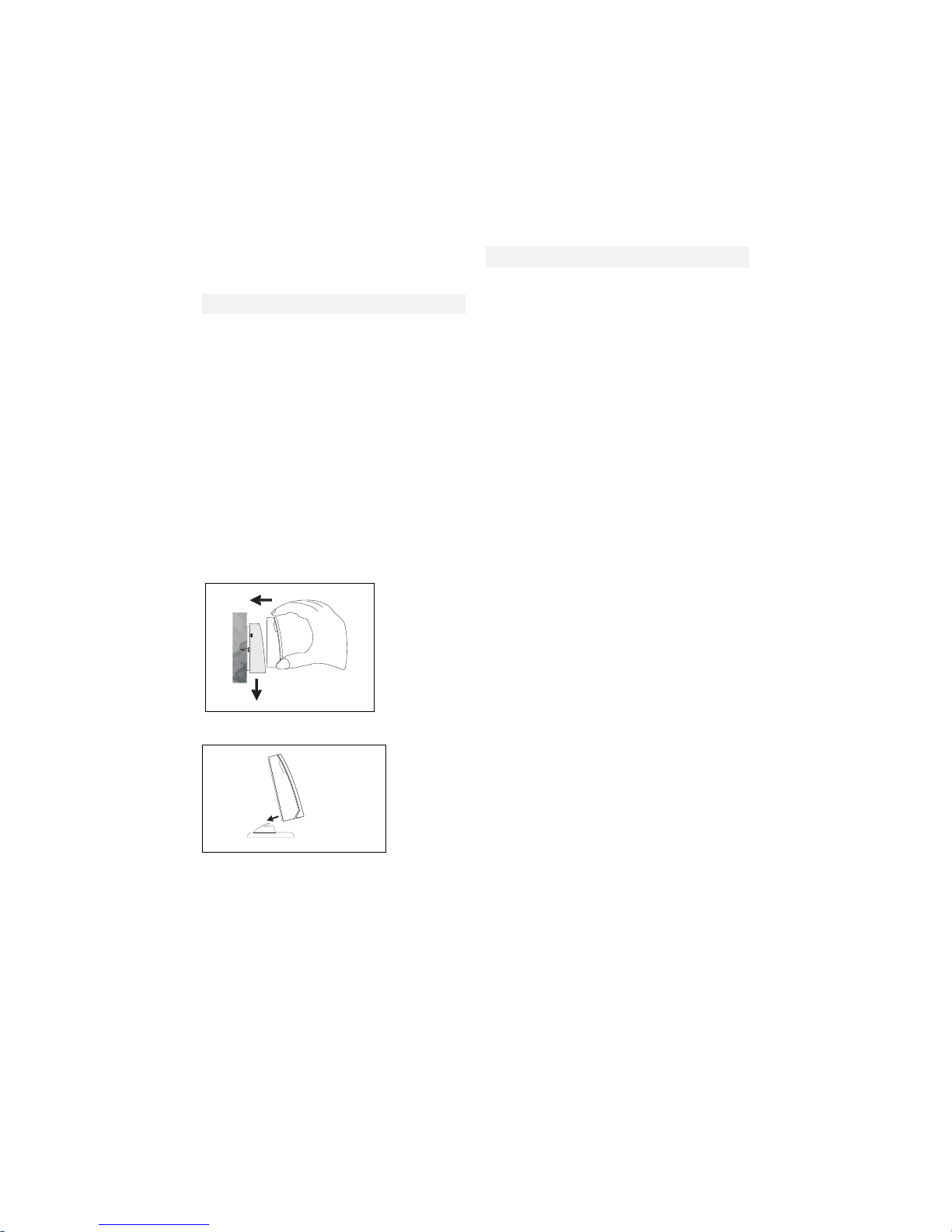
For wall-mounting applications, detach the
back-plate from the RFT by inserting a small
flat bladed screwdriver on the bottom underside of the unit.
Use a combination of suitable mounting
holes on the back-plate to secure the back-
plate to the wall at a height of 1.5-metres
from the floor.
Once the unit is powered via the batteries,
the display is active and the default settings
are enabled.
PROGRAMMING PROCEDURE
Rotate the program selector to the MENU
position, using the buttons you can
scroll through the main menu:
• TARGET TEMP
• SERVICE
• HOLIDAY
• PROGRAM P3
• CLOCK/DATE
3.4.1 TARGET TEMP MENU
Using the programming procedure, scroll
through the main menu until TARGET TEMP
is displayed; press the OK button to select
the sub menu:
• COMFORT – temperature required when
the heating is ON
• LOWER – temperature required when the
heating is OFF
• FROST – setting level when the program
selector is in the frost protection mode or
the HOLIDAY function has been enabled
Use the buttons to select the desired
temperature/s and press OK to confirm or
ESC to cancel any changes.
3.4.2 SERVICE MENU
Using the programming procedure, scroll
through the main menu until SERVICE is
displayed; press the OK button to select the
sub menu; use the buttons to select the
desired function:
• HW IMMEDIATE
• CODING
• TEST RF
• CONTROL
• WALL COMP
• OPTIMISATION
• DISPLAY
• HOT WATER
• LANGUAGE
3.3 MOUNTING/LOCATION
3.4 MENUS AND SUB-MENUS
Wall mounting
Free-standing
3
Page 5

See section 5.0 for more detailed information on the SERVICE functions.
3.4.3 HOLIDAY MENU
Using the programming procedure, scroll
through the main menu until HOLIDAY is
displayed; press the OK button to select the
sub menu; use the buttons to program:
• START HOLIDAY – the date and time
when you want the holiday period to begin
• END HOLIDAY – the date and time when
you want the holiday period to end
• FROST SETTING – the operating tempera-
ture that is active during the holiday period
• CHECK – used to check the above pro-
grammed details
• CLEAR – used to clear or cancel the
holiday settings or activity.
3.4.4 PROGRAM P3 MENU
Using the programming procedure, scroll
through the main menu until PROGRAM P3
is displayed; press the OK button to select
the sub menu; use the buttons to select
the desired function:
• HEATING – programme your own individual
ON/OFF times for the central heating
• HOT WATER – programme your own in-
dividual ON/OFF times for hot water
See section 4.0 for more detailed information on the PROGRAM P3 functions.
3.4.5 CLOCK/DATE MENU
Using the programming procedure, scroll
through the main menu until CLOCK/DATE
is displayed; press the OK button to change/review; use the buttons to change/
amend the date and time as follows:
The selector can be positioned to enable the
various modes of operation as well as the
MENU position.
P3 – move the program selector to this position if you want to use your own specific programme for heating and hot water (see 4.0)
P2 – is a fixed programme; comfort temperature is active during Mon - Fri 6 - 8 am, 4 10 pm, and Sat - Sun 7 am - 11 pm. The
lower temperature is active at all other times
P1 – is a fixed programme; comfort temperature is active during Mon - Fri 6 am - 10
pm, and Sat - Sun 7 am - 11 pm. The lower
temperature is active at all other times
- Comfort temperature setting: when the
selector is in this position, the room temperature is permanently maintained at the
comfort value
- Lower temperature setting: when the
selector is in this position, the room temperature is permanently maintained at the
lower value
- Frost protection setting: when the selector is in this position, the room temperature is permanently maintained at the frost
protection value
With the INFO button, you can check/display
the following:
• Current room temperature
• Target room temperature
• Required hot water temperature
• Date and time
• Current operating mode
• Current display mode
• Switching times of the current program
(only visible when the hinged cover is
open)
1. The display shows the time setting.
2. Set the current time with the buttons
and :
Set the hour and confirm with the OK
button.
Set the minutes and confirm with the
OK button.
Hour
0:00
OK
Hour
15:00
OK
Minute
15:34
With the ESC button you can always return
to the previous programmming step in order
to adjust a setting.
1. The display shows the time setting.
2. Set the current time with the buttons
▲ and ▼:
Set the hour and confirm with the
OK button.
Set the minutes and confirm with
the OK button.
OK
Year
2002
Month
04
OK
Day
09.04
OK
3. The display changes automatically
to the date setting.
Set the year, month and date one
after the other. Confirm each setting with the OK button. The display changes automatically.
3.5 PROGRAM SELECTOR
3.6 INFO BUTTON
4
Page 6

By using the buttons, you can temporarily alter the target temperature (up or down)
until the next temperature change, e.g. from
Comfort to lower.
• Press either of the buttons to display
the current target temperature
• Continually press the button to increase
the target temperature, or the button to
decrease the target temperature until the
required temporary value is displayed
• After 3-seconds, the display will automati-
cally return to its original state and the
thermostat will regulate to the new temporary value
• When the selector is in either of the perma-
nent Comfort – Lower – Frost settings,
the temporary target temperature is maintained until the selector is moved or a new
temporary value is chosen.
With the party/eco function you can temporarily change the set temperature profile up
to a maximum period of 23-hours and 50minutes.
• Press and hold both buttons simulta-
neously for 2-seconds
• The display changes and shows PERIOD
and a flashing clock; within the 3-seconds
press either button to move the display to the required time period
(increments of 10-minutes).
• After 3-seconds, the display changes and
shows flashing text COMFORT or LOWER.
If necessary, use the buttons to change the display to show COMFORT or
LOWER in order to select the preferred
temperature regime for the set period.
• The display changes automatically after
3-seconds to show the desired temperature
regime ECO (lower) or PARTY (comfort);
the party/eco program is now active for the
period selected.
• The party/eco function can be cancelled by
pressing and holding both buttons
simultaneously for 2-seconds and then wait
for 3-seconds; the display will revert to normal and the party or eco function will be
cancelled.
To program bespoke time settings for the
heating and hot water proceed as follows:
STEP-1:
Rotate the selector to the MENU setting and
select PROGRAM P3 and then select NEW
from the sub-menu
MENU
TARGET TEMP
Service
Holiday
PROGRAM
Clock/Date
OK
New
Check
Clear
End
5.3.2 Creating a new temperature profile P3
HOUR
16:00
MINUTE
16:30
New
Free
21
Mo-Fr
Sa/Su
Daily
3
sec.
Monday
Tuesday
Wednesday
Thursday
Friday
Saturday
Sunday
Lower
Comfort
END
Single day
Display of the free
memory areas
OK
OK
OK
OK
OK
OK
3sec.
back to
NEW
OK
STEP-2: Select the day or group of days that are to be programmed and then select the time periods
Display of the free
memory areas
back to
3.8 PARTY/ECO PROGRAM
4.0 PROGRAMMING
3.7 TEMPORARY ADJUSTMENT OF THE
TARGET TEMPERATURE
5
Page 7

5.3.3 Checking the temperature profile P3
By pressing the OK or button, all
switch times of the day are dis-
played one after the other. Once
the last switch time is reached, the
switch times ofthe next day are dis-
played etc.
CHECK
7654321
PROG
6:00
0
6915182124h
21 . 0 C
END
3sec.
Empty
no program stored in memory
back to
Program
see 5.3.1
OK
OK
back to
Program
see 5.3.1
no program stored in memory
By pressing the OK or ▲ button, all
switch times of the day are displayed
one after the other. Once the last switch
time is reached, the switch times of the
next day are displayed etc.
back to
back to
STEP-3: You can confirm time settings via the sub-menu
STEP-4: You can clear time settings via the sub-menu
5.3.4 Clearing the temperature profile
CLEAR Single
All
END
back to
Single
see
5.3.5
see
5.3.6
OK
back to
5.3.5 Displaying individual switch times and clearing them
5.3.6 Clearing all switch times
The switch times are dis-
played one after the other.
Display next switch time
with .
Single
Empty
7654321
PROG
6:00
036912151821
24h
21 . 0 C
no program stored in memory
7654321
PROG
6:00
036912151821
24h
Loeschen
END
The switch time is
cleared and the next
switch time is displayed.
3sec.
Display of the switch time
In order to clear the
displayed switch time,
press the OK button.
OK
back to
Program
see 5.3.1
OK
back to
Program
see 5.3.1
OK
OK
1. Displaying the switch
times
2. Clearing the desired
switch times
Clear
All
Empty
no program stored in memory
Confirm
In order to cancel the
clearing process, press
the ESC button.
back to
Program
see 5.3.1
OK
OK
OK
back to
Program
see 5.3.1
Displaying individual switch times and clearing them
Displaying the switch
times
Clearing the desired
switch times
Clearing all switch times
no program stored in memory
In order to clear the displayed switch time, press
the OK button.
The switch time is cleared
and the next switch time
is displayed.
The switch times are displayed
one after the other. Display
next switch time with ▲.
no program stored in memory
back to
back to
back to
back to
In order to cancel the clearing
process, press the ESC button.
6
Page 8

Using the programming procedure, scroll
through the main menu until SERVICE is
displayed; press the OK button to select the
sub menu; use the buttons to select the
desired function:
• HW IMMEDIATE
• CODING
• TEST RF
• CONTROL
• WALL COMP
• OPTIMISATION
• DISPLAY
• HOT WATER
• LANGUAGE
With this function, household water can be
heated and enabled once, regardless of the
times set in the program.
Setting with the buttons or . Confirm
the value with OK (cancel with ESC).
This function is used to ‘pair’ the transmitter
with the receiver. Transmitter and receiver
are already ‘paired’ at the factory so during
normal installation and use, it’s not necessary to carry out this function; see section 2 for
more detailed information.
See section 2.1
Characteristics of the PD controller
With suitable heating systems the PD controller is characterized by a short setting
time, scarce maximum overshooting and
therefore a high control accuracy.
Characteristics of a hysteresis controller
With over or under engineered heating systems a hysteresis controller is characterized
by scarce shift frequency and small temperature deviations.
If required, the transmitter can be calibrated
to account for temperature differentials between the mounting location (wall) and the
ambient room temperature, e.g. if the transmitter is located on a wall that is an external
wall of the dwelling.
Example: The difference between the measured and the controlled temperature is 2 °C,
i.e. the room temperature is regulated 2 °C
too high: Offset value –2 °C.
MENU
TARGET TEMP
Service
Holiday
PROGRAM
Clock/Date
OK
Display
Language
Wall comp
Control
End
see 5.4.2
see 5.4.3
see 5.4.4
see 5.4.5
test hf
coding
Wall comp
Wall comp
0.0oC
OK
OK
5.0 SERVICE MENU
5.1 HW IMMEDIATE
5.4 CONTROL
5.5 WALL COMP
5.2 CODING
5.3 TEST RF
WW-SOFORT
OK
AUS
EIN
EINSTELLUNGEN
hw immediate
settings
off
on
OK
Control
Hyst control
Pd control END
Amplitude
0.2oC
Period
10
Hysteresis
0.3oC
Offset
0.3oC
Set with buttons
or :
0.2°C ... 5.0°C
5 ... 30
0.1°C ... 0.2°C
END
or autom.
after 6 sec.
OK
OK
OK
OK
OK
OK
OK
OK
back to
Service
see 5 .4.1
Set with buttons
or :
0.2°C ... 1.0°C
5 … 30
0.1 °C ...0.2 °C
Set with buttons
▲ or ▼:
0.2 °C ...5.0 °C
back to
or autom.
after 6 sec.
see 5.4.1
Set with buttons
▲ or ▼:
0.2 °C ...1.0 °C
7
Page 9

Offset value adjustable from –3 °C ... +3 °C.
Setting with ▲ or ▼. Confirm the value with
OK. Cancel with ESC.
The optimal start function – when enabled –
starts the boiler (prior to the timed ON period) in order to have the room at the comfort temperature level when the Timed ON
period begins.
The optimal start function can be set from 0minutes (optimisation is disabled) up to 60minutes. The unit measures the temperature
differential between the actual (room) temperature and the target – comfort – temperature and starts the boiler the set period of
minutes for each degree of differential that
exists.
Example:
• Optimisation is set at 10-minutes
• ON (comfort) period begins at 6:00 am
• Temperature differential (between actual
18 °C and comfort setting 21 °C) is 3-degrees
• Therefore 3 x 10 = 30-minutes
• Boiler is started at 5:30 am to ensure room
is at comfort level for 6:00 am
The normal display can be changed to show
different information.
Select the display type with the button ▲ or
▼. Confirm with the OK button.
Cancel with ESC.
Note: The factory stetting is highlighted grey
in the table.
You can choose to have the unit manage
the timed settings of the hot water function,
or both time settings and outlet temperature.
The following languages can be selected via
the LANGUAGE function:
• English
• German (Deutsch)
• Italian (Italiano)
• Portugese (Portugues)
• Dutch (NL)
• Spanish (Espanol)
• French (Francais)
Rotary switch position
P1, P2 or P3
Rotary switch position
Display type Display type
12
34512345
Time T T
N N
Target temp. N
NT NN
Actual temp. N
NTN N
Program name
TTTTT
Table: Overview of the information shown in the display for different
display types.
7654321
PROG
6:00
0
6915182124h
21 . 0 C
T = text line
N = numerical display
T = text line
N = numerical display
Table: Overview of the information shown in the display for
different displays types.
Language
Francais
English
Deutsch
NL
Espanol
Italiano
Select the language with the buttons or .
Confirm with the OK button. Cancel with ESC.
OK
back to
Service
see 5.4.1
OK
back to
Select the language with the buttons
▲ or ▼. Confirm with the OK button.
Cancel with ESC.
hot
water
hw time only
hw time/temp
Display
Display
3
OK
OK
5.6 OPTIMISATION
5.8 HOT WATER
5.9 LANGUAGE
5.7 DISPLAY
8
Page 10

See example below
Reset button >
Time: 12:00
Date: reset
Holiday program: clear
(See 4.0 Step 4 to clear all programs)
Control type: RS type 1 acc. to
EN 60730-1:1991
Accuracy: ± 1 sec. per day at 20 °C
Control accuracy: ± 0.2 K
Temperature meas. range:
O °C to 50 °C,
resolution 0.1 °C
Temperature setting range:
6 °C to 30 °C in increments
of 0.2 °C
Control period: 5 to 30 min. (PD control)
Control lock-in range:
± 0.2 K to ± 5 K (PD control)
Switching hysteresis:
± 0.2 K to ± 1 0 K
(hysteresis control)
Memory spaces: 32 temperature changes,
programmable for Mo-Fr,
Sa-Su, each day or for
individual days
Class of protection:
III according to EN 60730-1
Type of enclosure:
IP 20 according to
EN 60529-1
Batteries: 2 x alkaline batteries 1.5 V,
type AA
Power reserve during battery emplacement:
10 minutes
5.5 Time/Date and Summer/Winter Time
OK
MENU
Service
TARGET TEMP
CLOCK/DATE
PROGRAM
HOLIDAY
Hour
Day
With s/w
OK
USA/CAN
SF/GR/TR
Gb/P
Europe
OK
OK
END
End
No su/wi
Free
OK
Setting the time and date:
hour, minute, year, month, day.
Description see page 18.
Month su
03:01
OK
Week su
03:02
Hour
02:00
Month wi
10:00
OK
OK
Week wi
10:02
OK
OK
END
back to
Clock/Date
Start of summer time:
Month
Weekend within
month
Hour for changeover:
e.g. from 2 a.m. to
3a.m.
Start of winter time:
Month
Weekend within month
OK
Note: Time for changeover to winter time is taken
from summer time, e.g. back from 3 a.m. to2 a.m.
OK
3sec.
Time/Date and Summer/Winter Time
Setting the time and date:
hour, minute, year, month, day.
Description see chap. 4.3.
Start of summer time:
Month
Weekend within
month
Weekend within monthHour for changeover:
e.g. from 2 a.m. to
3 a. m.
Start of winter time:
Month
Note: Time for changeover to winter time is taken from summer time, e.g. back from 3 a.m. to 2 a.m.
back to
7.0 RESET
8.0 TECHNICAL SPECIFICATION
6.0 TIME – DATE – SUMMER/WINTER
TIME
9
Page 11

With the exception of a regular replacement
of the batteries for the transmitter, the room
thermostats are maintenance-free.
Only clean the device with a dry or slightly
damp, soft and lint-free cloth. The interior of
the device must remain free from water.
Replace the two batteries at regular intervals
every 1.5 years. Only use new 1.5 V batteries of the type AA, Alkaline. Never mix old
and new batteries, as old batteries can leak.
Disposal of Batteries
Used batteries must be disposed of according to the national regulations with regard
to the environment (e.g. at special battery
collection outlets). Never throw used batteries out with your usual rubbish.
Disposal of the Device
At the end of its life, the room thermostat
must be dismounted professionally and disposed of according to the national regulations with regard to the environment.
In case of doubts, please contact the manufacturer’s representative in your country.
9.0 MAINTENANCE
10.0 DISPOSAL
10
Page 12

Registered address:
Vokèra Ltd
Borderlake House
Unit 7 Riverside Industrial Estate
London Colney
Herts AL2 1HG
enquiries@vokera.co.uk
www.vokera.co.uk
www.vokera.ie
Sales, General Enquires
T 0844 391 099
F 0844 391 0998
Vokèra Ireland
West Court, Callan
Co Kilkenny
T 056 7755057
F 056 7755060
Vokèra Limited reserve the right to change
specification without prior notice
Consumers statutory rights are not affected.
A Riello Group Company.
Company Reg No: 1047779
 Loading...