

Page 1
~ DOMESTIC HEATING APPLIANCES
®
~
..
'---.J
..
..
l-
Meteor
890
Users
Instructions
CE
British Gas Service Listed
G.C. No. 47 094 21
HAND THESE
INSTRUCTIONS
TO THE USER
Page 2
BEFORE ATTEMPTING TO LIGHT APPLIANCE PLEASE MAKE SURE THAT IT IS CHARGED UP WITH
WATER WITH THE NEEDLE POINTING AT 1bar ON THE PRESSURE GAUGE (4)
Gas Safety (Installation and Use) Regulations 1994
In your own interests and that of safety, it is the law that all gas appliances are installed and serviced by a
competent person in accordance with the above regulation.
GAS LEAK OR FAULT
IF A FAULT OR GAS lEAK IS SUSPECTED, TURN OFF THE APPLIANCE AND CONTACT YOUR INSTAllATION
COMPANY OR lOCAL GAS REGION.
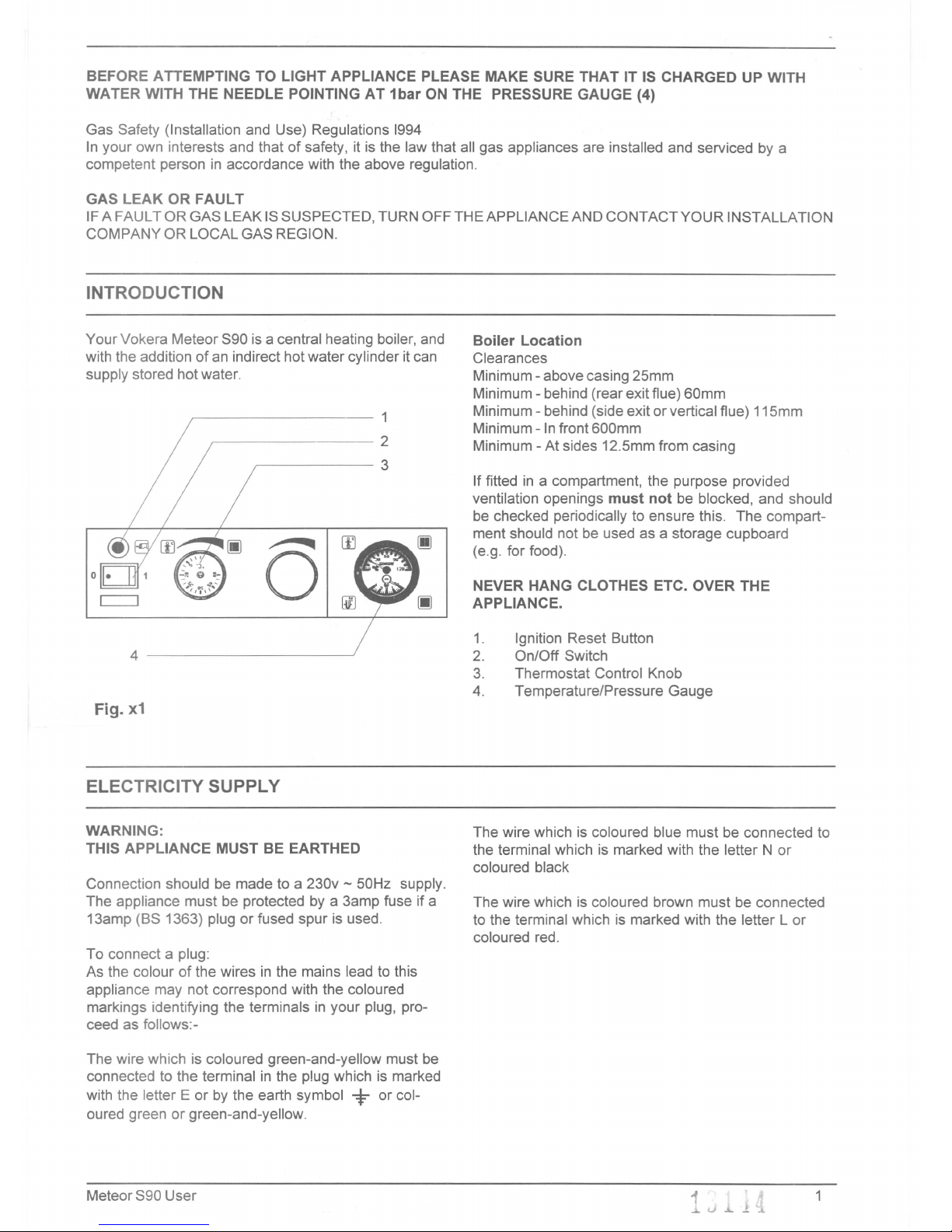
Your Vokera Meteor S90 is a central heating boiler, and
with the addition of an indirect hot water cylinder it can
supply stored hot water.
-1
2
3
Boiler Location
Clearances
Minimum - above casing 25mm
Minimum - behind (rear exit flue) 60mm
Minimum - behind (side exit or vertical flue) 115mm
Minimum - In front 600mm
Minimum - At sides 12.5mm from casing
If fitted in a compartment, the purpose provided
ventilation openings must not be blocked, and should
be checked periodically to ensure this. The compart-
ment should not be used as a storage cupboard
(e.g. for food).
NEVER HANG CLOTHES ETC. OVER THE
APPLIANCE.
Ignition Reset Button
On/Off Switch
Thermostat Control Knob
Temperature/Pressure Gauge
WARNING:
THIS APPLIANCE MUST BE EARTHED
Connection should be made to a 230v - 50Hz supply.
The appliance must be protected by a 3amp fuse if a
13amp (BS 1363) plug or fused spur is used.
To connect a plug:
As the colour of the wires in the mains lead to this
appliance may not correspond with the coloured
markings identifying the terminals in your plug, pro-
ceed as follows:-
The wire which is coloured green-and-yellow must be
connected to the terminal in the plug which is marked
with the letter E or by the earth symbol
i=-
or col-
oured green or green-and-yellow.
The wire which is coloured blue must be connected to
the terminal which is marked with the letter N or
coloured black
The wire which is coloured brown must be connected
to the terminal which is marked with the letter l or
coloured red.
Page 3

1.0
LIGHTING THE BOILER.
3.0
SHUTTING DOWN THE SYSTEM
For short periods:
1.1 Switch on the electrical supply at the mains Turn the on/off switch (2) to
0
isolated point.
For longer periods also:
1.2 Ensure the gas supply to the appliance is turned Turn off gas cock and
on. Turn off main electricity supply to boiler.
1.3 To gain access to the control facia, lower the However, if the building is vacated when there
upper panel by use of the key provided. is risk of freezing shut down the boiler as
NOTE: If additional keys are required they can
described and drain the system:
be obtained by contacting your local spare parts
stockist.
Open all heating radiator valves, open the drain
cock within the appliance as well as drain cocks
1.4 Turn the on/off switch (2) to 1
usually provided at the lowest point of the
system. To ensure draining of radiators, open
1.5 Should the appliance have external controls i.e. radiator air cocks remembering to close them
room thermostat or timeclock, ensure that they when the operation is complete.
are turned on and are calling for heat. The
appliance will now go through an ignition Alternatively, install a frost stat and leave the
sequence and the burner will light. mains electricity and gas supply turned on.
1.6
Should the appliance fail to ignite and the N.B. Refilling a sealed system must be undertaken
ignition reset button (1) illuminate. Depress the
by a competent person following approved
ignition reset button and the boiler will go
procedures.
through the ignition sequence again. If the cut
out operates again, the appliance must be 4.0
RELIGHTING THE BOILER
checked by a competent person, before relight-
Relight by following steps 1.0to 1.6 given
ing.
previously, after ensuring that refilling&venting
of the sealed system has been carried out.
1.7 Adjust the Central heating temperature control
(3) to suit the weather conditions.
5.0 CLEANING THE OUTER CASE
Use a clean damp cloth. Do not use abrasive
N.B (i) For the quickest heat up of the premises the
cleaners.
highest setting is needed at first, turning down
later. 6.0
SPARE PARTS AND SERVICING
Your Vokera Meteor must be serviced annually.
(ii) When Room Thermostats are used it may Please contact your local Vokera Service
be best to leave the boiler thermostat at a high Agent, your local Gas Region or a competent
setting and set the room thermostat as required. Installer.
2.0
SAFETY LIMITS
7.0 FLUE
In cold or humid weather water vapour may
2.1
Systems pressure
condense when leaving the flue terminal. The
The water pressure gauge (4) must read be-
effect of such steaming is normal.
tween 1 and 1.5bar when the system is cold.
Leaks or radiator venting will reduce this. Call in
your service installer if excessive topping up of
the system to restore pressure is necessary. A
built-in safety valve operates if boiler pressure
exceeds 3bar whether hot or cold. If the safety
valve operates (water/steam discharges to
drain) switch off and call your Installer or
Service Engineer.
2.2 If the appliance water temperature rises too
high, a high limit thermostat operates to extin-
guish the burner. This will reset automatically
when the boiler temperature cools to within the
working limits. If the cut out operates again, the
appliance must be checked by a competent
person, before relighting.
2
Meteor S90 User
.J....J..L /
1. ~
Page 4

Vokera
G.R
Claudio (Vokera) Ltd
Head Office and Accounts: Clarisham House, Morson Road, Enfield, Middlesex EN3 4NQ Tel. 0181-804 7202 Fax. 0181-804 8163
Northern Region: Stubs Beck Lane, West 26 Business Pari<,Whitehall Road, Clec:kheaton,West Yori<shireBD19 4TT Tel. 01274865556 Fax. 01274 865557
ScoUish Region: ShunaStreet, Maryhill, GlasgowG209NWTel. 0141-9454944 Fax. 0141-9455136
 Loading...