

Page 1
Supplied By www.heating spares.co Tel. 0161 620 6677
Room Sealed, Fanned Flue, Combination Boiler
Installation
& Servicing
Instructions
BRITISH GAS SERVICE LISTED
G.C. No 47 094 30
THESE INSTRUCTIONS
TO BE RETAINED
BY USER
Page 2

Supplied By www.heating spares.co Tel. 0161 620 6677
Page 3

Supplied By www.heating spares.co Tel. 0161 620 6677
CONTENTS
Section Subject Page no
Section 1 Introduction 1
General Layout 1
Section 2 Design Principles & Operating
Principles 2
Schematic Diagram 2
Central Heating Mode 2
Domestic Hot Water Mode 2
Safety Devices 2
Frost Thermostat 2
Section 3 Technical Data 3
Dimensions & Contents 3
Connection Sizes 3
Installation Requirements 3
Electrical Details 3
Performance & Limitations 3
Working Pressure (H/W & C/H) 4
Flow Rates 4
Central Heating Pump Duty 4
Section 4 General Requirements 5
Related Documents 5
Location of Appliance 5
Gas Supply 5
Flue System 5
Air Supply 6
Water Circulation (C/H) 6
Pipework 6
By-Pass 6
System Design 6
Draining Taps 6
Air Release Points 7
Filling Point 7
Electrical Supply 7
Showers 7
Section 5 Installation 8
Delivery 8
Unpacking 8
Siting the Appliance 9
Connecting the Gas & Water 9-10
Fitting The Flue (Horizontal) 13
Fitting The Flue (Vertical) 14
Electrical connections 22
Section 6 Commissioning 17
Gas Installation 17
Initial Flushing of Pipework 17
Initial Filling of System 17
System Design Pressure 17
Filling the Hot Water System 17
Checking Electrical supply 17
Lighting The Boiler 17
Checking Burner Pressures 18
Range Rating C/H 19
Checking The Flue System 19
Checking The Heating Thermistor 19
Regulating The C/H System 19
Final Flushing The C/H System 19
Filling & Testing H/W System 19
Final Checks For Operation 20
Concluding Operations 20
Section Subject Page no
Section 7 Instructing The User 20
Section 8 Servicing Instructions 20
General 20
Recommended Routine Servicing 20
Annual Servicing 20
Replacement Of Parts 21
To Gain General Access 21
To Remove:
Room Sealed Chamber Front Cover 21
Main Burner & Electrode 22
Main Burner Injectors 22
Main Heat Exchanger 22
Flue Fan 23
Pressure Differential Switch 23
Combustion Chamber Insulation Panel 23
Ignition Control Box 24
Gas Control Valve 24
Pump 25
Domestic Flow Switch 25
Diverter Valve & Flow Switch Manifold 25
Domestic H/W Heat Exchanger 26
Diverter Valve 26
Main Expansion Vessel 26
Safety Valve 26
Flow Microswitch 26
Motorised Valve 26
Printed Circuit Board 26
Display Printed Circuit Board 26
Safety Thermostat 26
Thermistor Sensors 26
Pressure Gauge 26
Setting Gas Pressures 27
Combustion Analysis 27
Section 9 Operational Checks & Wiring 28
Sequence of Functions 28
Diagnostic Error Codes 29
Fault Finding Guides 30-40
Section 10 Appendix 41
Internal Time Clock Installation 41-42
External Time Clock Installation 42
S & Y Plan Installations 43
Exploded Diagrams 45-51
Short Spare Parts List 52
Abling & Disabling Controls 52
Functional Flow Diagram 53
Illustrated Wiring Diagram 54
Preliminary Electrical System Checks 55
LPG Instructions 56-57
Linea Max
Page 4

Supplied By www.heating spares.co Tel. 0161 620 6677
Page 5
Supplied By www.heating spares.co Tel. 0161 620 6677
SECTION 1 INTRODUCTION
26
25
24
23
22
21
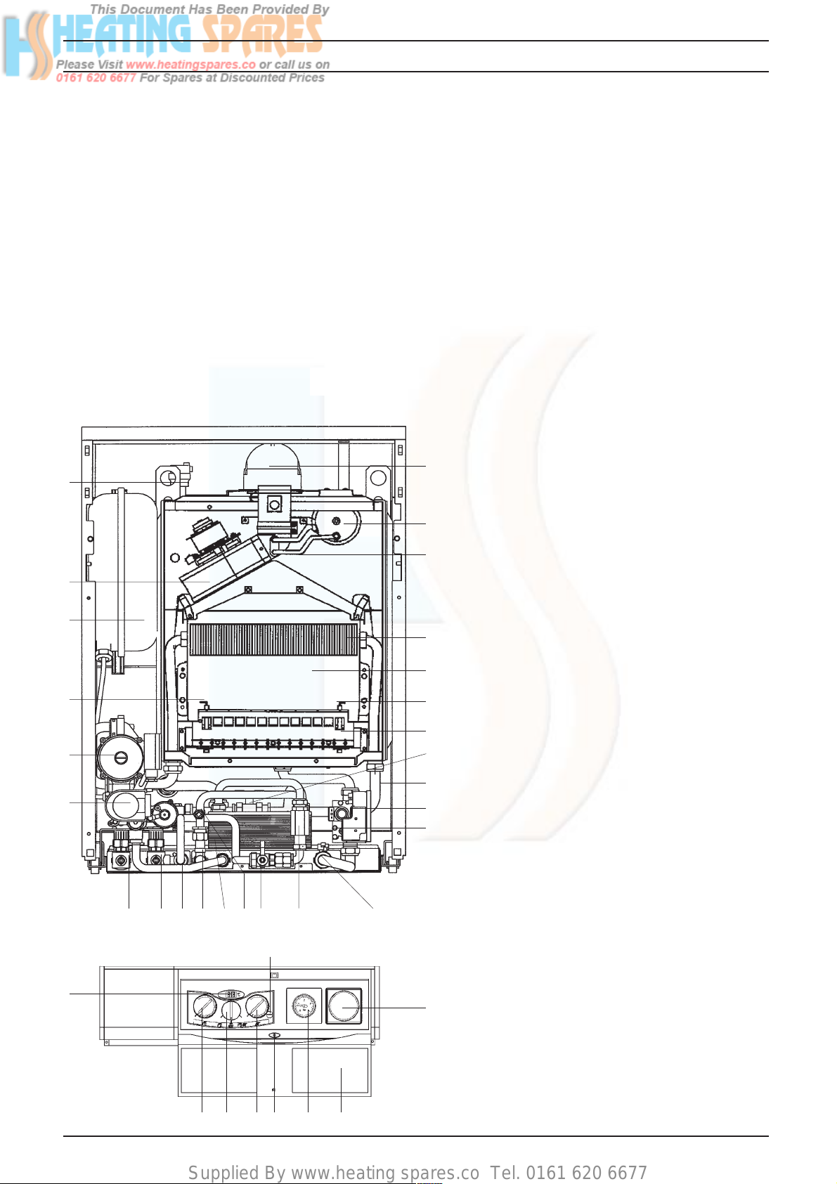
The Vokèra Linea Max is a combined central heating and domestic hot
water appliance. By design it incorporates
full sequence electronic ignition, circulating
pump, expansion vessel, safety valve,
temperature gauge, pressure gauge, 3 port
diverter valve and filling loop.
It is produced as a room sealed appliance
suitable for floor mounting only. It is provided with a fan powered flue outlet with an
annular co-axial combustion air intake, twin
flue option is also available.
Fig. 1
14 13
35
This appliance is designed for use with a
sealed heating system only and is not
intended for use on an open vented system.
An automatic range-rating facility is incorporated in the boiler for the central heating
system in conjunction with the electronic
burner modulation. The domestic hot water
(dhw) service utilises a motorised valve
combined with a 3 port diverter valve to give
hot water priority which also benefits from a
heatbank having a nominal capacity of 58
litres of circulating primary hot water positioned at the rear of the appliance.
Fig.1 General Layout
1 Flue Elbow
2 Pressure Differential Switch
3 Silicone Pressure Tubes
1
4 Main Heat Exchanger
5 Combustion Chamber
6 Spark Electrode
7 Main Burner
2
8 Primary Store Isolation Valve (1 of 3)
9 Primary Store
3
10 Electronic Ignition Unit
11 Gas Valve
12 Gas Inlet
13 Domestic Flow Switch
14 Filling/Inlet Valve
4
15 Domestic NTC
16 Domestic Heat Exchanger
5
17 Hot Water Outlet
18 Safety Valve Outlet
19 Central Heating Flow
6
20 Central Heating Return
7
21 Motorised Valve
22 Pump
8
23 Sensing Electrode
24 Expansion Vessel
9
25 Fan
10
26 Automatic Air Vent
27 Timeclock Aperture (Optional)
11
28 Front Door Panel
29 Pressure Gauge
30 Status LED
31 Central Heating Temperature Control
1216171820 19 15
32 Mode Selector Switch
33 Hot Water Temperature Control
34 Temperature Indicator
35 Combustion Switch
34
Linea Max
31
29 28303233
27
1
Page 6
Supplied By www.heating spares.co Tel. 0161 620 6677
SECTION 2 DESIGN PRINCIPLES AND OPERATING SEQUENCE
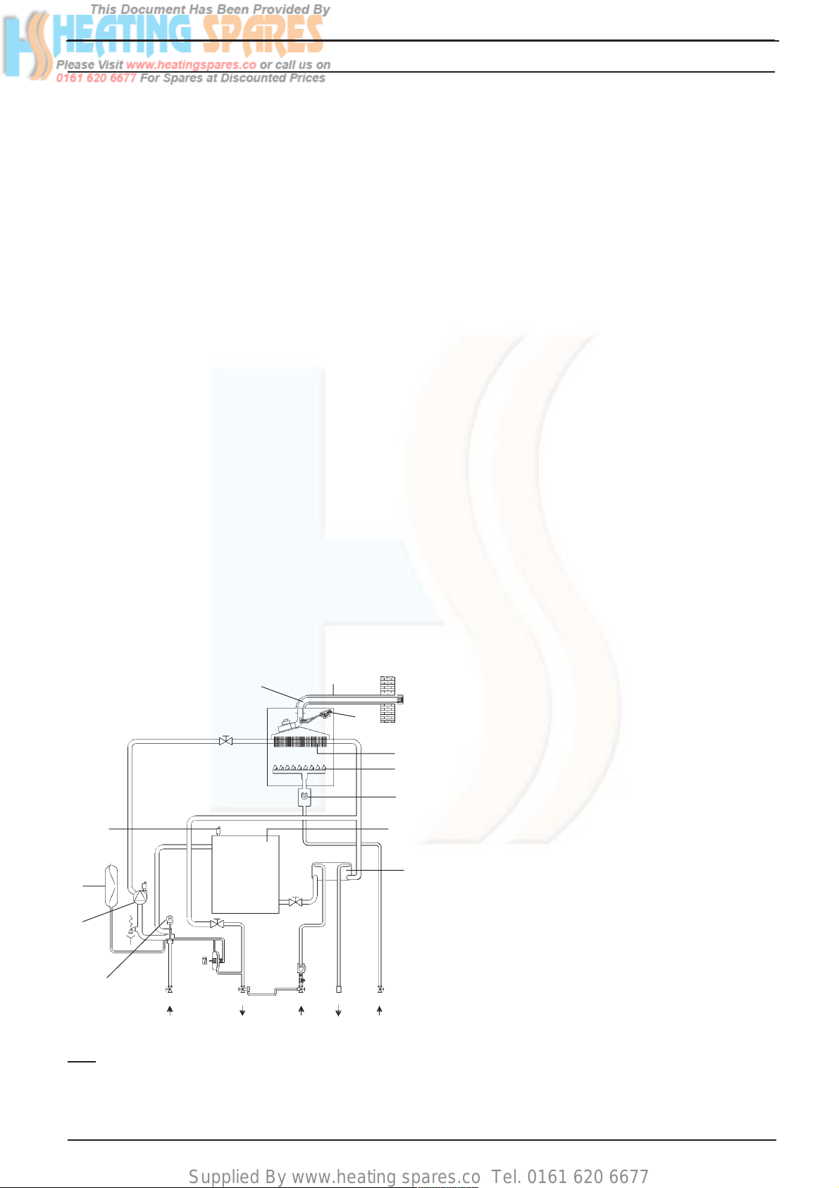
2.1 Fig.1 illustrates the general layout of components. Fig.2 illustrates the operating principles described below.
2.2 Central Heating Mode
2.2.1 When the various switches and controls
impose a demand for heat, the pump is
started. The flow of water from the pump
operates a flow switch. This in turn energises the electronic circuitry. The fan is
started, the gas valve is energised at an
intermediate rate and the electronic ignition
goes through an ignition attempt.
2.2.2 The burner ignition is checked by the electronic circuitry to ensure correct ignition of
the burner.
2.2.3 As water temperature increases this is
sensed by the temperature sensor on the
flow pipe which modulates the burner to
match the heat output to the heat requirement of the system.
2.2.4 Depending on the load, either a) the water
temperature will continue to rise and the
burner will continue to modulate down until
the maximum setting is reached at which
point the burner is switched off, or b) the
water temperature will fall and the burner
will return to a higher output to match the
demand.
flue outlet air intake
26
24
22
21
2.3 Domestic Hot Water Mode
2.3.1 The appliances incorporate a hot water
preheat facility. The appliance will therefore
ignite periodically to maintain heat within the
appliance.
2.3.2 The appliance will operate in domestic hot
water mode whenever the mode selector
switch is on regardless of mode selector
switch position and any demand for central
heating.
2.3.3 The diverter valve will automatically energise into the hot water position after central
heating demand, or will stay in the hot water
position after hot water demand. Opening a
draw off tap will energise the pump and fan
sending primary water to the domestic hot
water heat exchanger.
2.3.4 Temperature control is transferred to the
domestic hot water thermostat
(potentiometer) which modulates the burner
output between high and low flame to
maintain an average heat input to suit the
dhw output required.
2.3.5 An overrun is incorporated in the boiler in
both c/h & dhw modes. The fan overruns
until the boiler water cools to approximately
80°C (176°F).
2.4 Safety Devices
2.4.1 In both central heating and hot water modes
safe operating is ensured by:
A. Differential pressure unit in the primary
circuit which prevents burner operation if
water flow rates are too low.
B. An electronic device that checks the
primary pressure unit for activation. Failure
2
4
7
11
results in deactivation of the pump, after
approximately 10 minutes of operation.
C. A safety thermostat, which interrupts the
control circuit shutting off the gas valve. At
the same time the fan will still operate.
D. A Pressure differential switch in the flue
system to check the fan's operation before
9
allowing ignition.
2.4.2 A safety valve is provided to relieve excess
16
pressure from the primary circuit.
2.4.3 Frost Thermostat
The appliance has a built in frost protection
circuit. Should the boiler temperature sensed
at the primary thermistor fall below 5°C, the
boiler will operate in central heating mode and
continue to operate until the primary thermistor reaches approximately 40°C.
A
B
KEY:
A Gas
B Hot Water Outlet
DE
C
Fig. 2
This drawing is indicative only and does
not accurately represent pipe positioning.
C Cold Water Inlet
D Central Heating Flow
E Central Heating Return
2
Linea Max
Page 7
Supplied By www.heating spares.co Tel. 0161 620 6677
SECTION 3 TECHNICAL DATA
3.1 Units Dimensions and values are given in
the preferred Sl Units with Imperial units in
brackets where applicable.
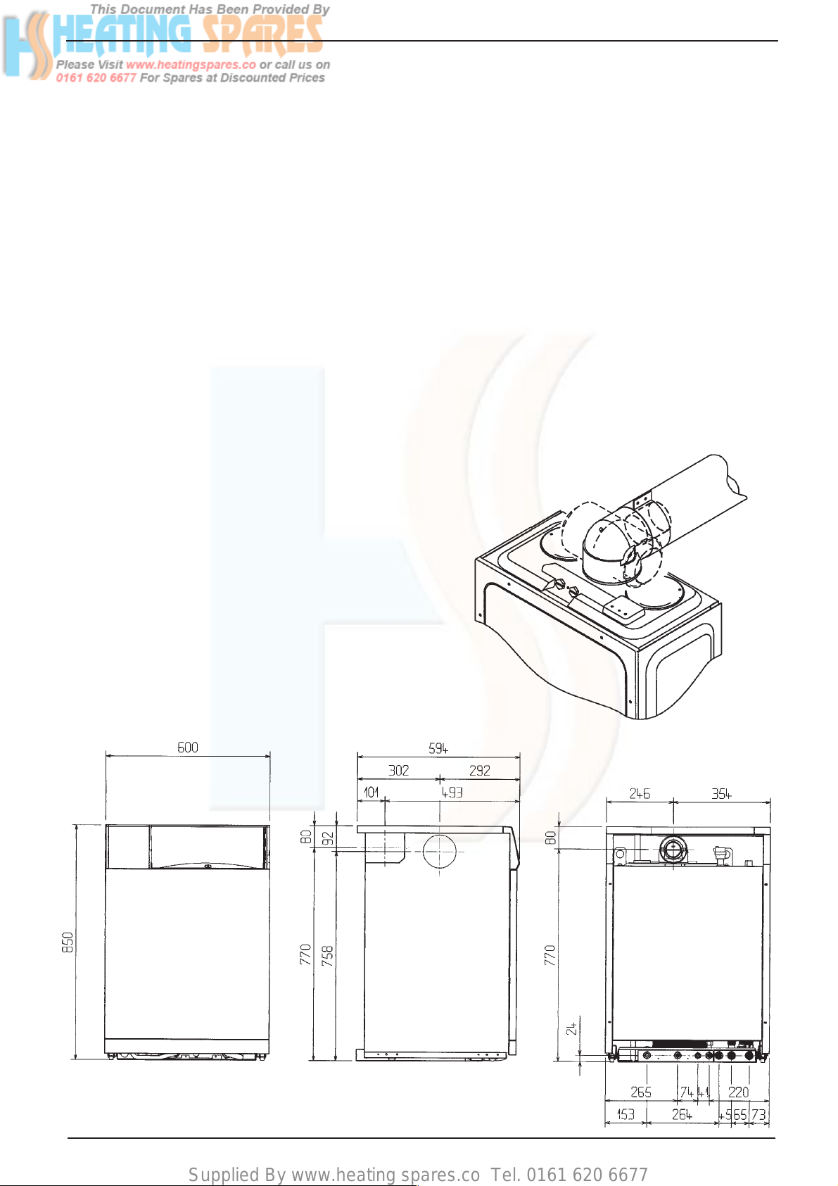
3.2 Dimensions and Contents
Height 850mm (33.5in.)
Width 600mm (23.6in.)
Depth 585mm (23in.)
Weight Dry 88Kg (194lb)
Weight Full 151Kg (333lb)
Water content: 65 litres (14.3 gals)
For further dimensions see fig.13
3.3 Connection sizes
Heating flow and return: Nut and olive for
22mm o.d.Cold water inlet: Nut and olive for
15mm o.d.Hot water outlet: Nut and olive for
15mm o.d. Gas Service: Nut and olive for
15mm o.d. Safety valve outlet: Nut and olive
for 15mm o.d.
Flue outlet/Air inlet: nom dia 60/100mm
specially supplied with boiler (concentric).
Flue outlet/Air inlet: nom dia 80/80mm
specially supplied with boiler (twin).
3.4 Installation Requirements
3.4.1 Clearances (Horizontal or Vertical Flue)
Minimum - above casing 20mm (3/4in)
Minimum - In front 600mm (24in)
Minimum - At sides 12mm (½in) from casing
3.4.2 Maximum heating system contents approx.
100 litres (21.9 gals). Acceptance capacity
of expansion vessel 10 litres (2.2 gals).
3.4.3 Means of filling sealed system: To accord
with BS and/or local Water Authority requirements.
3.4.4 Maximum flue lengths
Using extension tubes the flue may be
extended to the following lengths.
Concentric
Horizontal: 1.8 metres max.
Vertical: 4.4 metres max.
Twin: 6m/6m + concentric terminal.
(Horizontal termination only)
The reduction in flue length for each bend
used is:
Concentric Flue
Reduction in flue lenght
Bend
90° 850 mm
45° 425 mm
Offset 850 mm
for each bend
3.5 Electrical Details
Mains supply 230v ~ 50Hz Fused 3A
Internal fuse rating F2A and T100mA
Power consumption: 150W
3.6 Performance and Limitations
Max. input 31.0 kW (105,802 Btu/h)(net)
Min. input 11.9 kW (40,614 Btu/h)(net)(c/h)
Min. input 10.5 kW (35,836 Btu/h)(net)(h/w)
Max. input 34.4 kW (117,406 Btu/h)(gross)
Min. input 13.2 kW (45,051 Btu/h)(gross)(c/h)
Min. input 11.6 kW (39,590 Btu/h)(gross)(h/w)
Max. output 28.0 kW (95,563 Btu/h)
Min. output 9.9 kW (33,788 Btu/h)(c/h)
Min. output 8.7 kW (29,692 Btu/h)(h/w)
Central Heating output range
Max. 28.0 kW (95,563 Btu/h)
Min. 9.9 kW (33,788 Btu/h)
Designed temp rise 20°C
Max. flow temperature 85°C
Nominal hot water production
Max.water flow at temp rise of 25°C
16.1l/min Max.water flow at temp rise of
35°C 11.5l/min
Nominal hot water production (For first 10
minutes) (Inlet temp 12°C)
Water flow at 18 l/min - average water
temperature 43°C.
Gas Pressures
Max. gas pressure 10.1mbar
Min. gas pressure C/H 1.6mbar
Min. gas pressure H/W 1.3mbar
Gas Rate
Max. 3.27 m3/h 115.8 ft3/h
Min. 1.10 m3/h 39.0 ft3/h
Note: Use gross input values when gas
rating the appliance
Burner Details Main burner:
Polidoro type NP14
Main burner injectors 14 x 1.35
3.7 Working Pressure Heating System
Maximum 1.5bar/15m w.g./50ft w.g.
Minimum 0.15bar/1.5m w.g./5ft w.g.
Safety valve setting 3bar/30m/102ft w.g.
3.8 Flow Rates
Min. water flow (dhw) 2.0l/min. (0.45 gal/
min) Min central heating flow rate through
appliance 350litres/hr (1.28 gal/min)
3.9 Working Pressure Hot Water System
Maximum 6.0 bar/90psig
Minimum 0.6 bar/7psig
For LPG instructions see page 62
Twin Flue
Reduction in flue lenght
Bend
90° 850 mm
45° 850 mm
Linea Max
for each bend
3
Page 8

Supplied By www.heating spares.co Tel. 0161 620 6677
3.10 Central Heating Pump Duty
Water
pressure
mbar
700
600
500
400
300
200
100
0
123456789101112131415
X 100
Water flow
l/h
Fig. 3
4
Linea Max
Page 9
Supplied By www.heating spares.co Tel. 0161 620 6677
SECTION 4 GENERAL REQUIREMENTS
4.0 General Requirements
This appliance must be installed by a
competent person in accordance with the
Gas Safety (Installation & Use) Regulations
1998.
4.1 Related Documents
The installation of this boiler must be in
accordance with the relevant requirements
of the Gas Safety (Installation & Use)
Regulations 1998 the Local Building Regulations, the current l.E.E. Wiring Regulations,
the by-laws of the local water undertaking,
and in Scotland, in accordance with the
Building Standards (Scotland) Regulation. In
Ireland the local building regulations (IE).
It should be in accordance also with any
relevant requirements of the local authority
and the relevant recommendations of the
following British Standard Codes of Practice:
BS 6891 1988 Low pressure installation pipes
BS 6798 1987 Boilers of rated input not exceeding 60kW.
BS 5449 Part 1 1990 Forced circulation hot water systems
BS 5546 1990 Installation of gas hot water supplies
BS 5440 Part 1 1990 Flues.
BS 5440 Part 2 1989 Flues & Ventilation.
BS 7074 Part 1 1989 Application, selection & installation of expansion
A compartment used to enclose the boiler
must be designed and constructed specifically for this purpose. An existing cupboard
or compartment may be used provided that
it is modified for this purpose.
Details of essential features of cupboard/
compartment design including airing cupboard installations are given in BS
6798:1987. This appliance is not suitable for
external installation.
4.3 Gas Supply
A gas meter is connected to the service pipe
by the gas supplier.
An existing meter should be checked,
preferably by the gas supplier, to ensure that
the meter is adequate to deal with the rate of
gas supply required for all appliances it
serves.
Installation pipes should be fitted in accordance with BS 6891:1988.
for domestic purposes (2nd family gases).
vessels & ancillary equipment for sealed water
systems.
4.2 Location of Appliance
The combination boiler may be installed in
any room or internal space, although particular attention is drawn to the requirements
of the current l.E.E. Wiring Regulations, and
in Scotland, the electrical provisions of the
Building Regulations applicable in Scotland,
with respect to the installation of the combination boiler in a room or internal space
containing a bath or shower.
Where a room-sealed appliance is installed
in a room containing a bath or shower, any
electrical switch or appliance control, utilising mains electricity, should be located in
such a position that it cannot be touched by
a person using the bath or shower.
The location chosen for the boiler must
permit the provision of a satisfactory flue
and termination. The location must also
permit an adequate air supply for combustion purposes and an adequate space for
servicing and air circulation around the
boiler.
Where the installation of the boiler will be in
an unusual location special procedures may
be necessary and BS 6798:1987 gives
detailed guidance on this aspect.
Pipework from the meter to the boiler must
be of adequate size. Pipes of a smaller size
than the boiler inlet connection must not be
used.
The complete installation must be tested for
soundness as described in the above code.
N.B. If the gas supply for the boiler serves
other appliances ensure that an adequate
supply is available both to the boiler and the
other appliance when they are in use at the
same time.
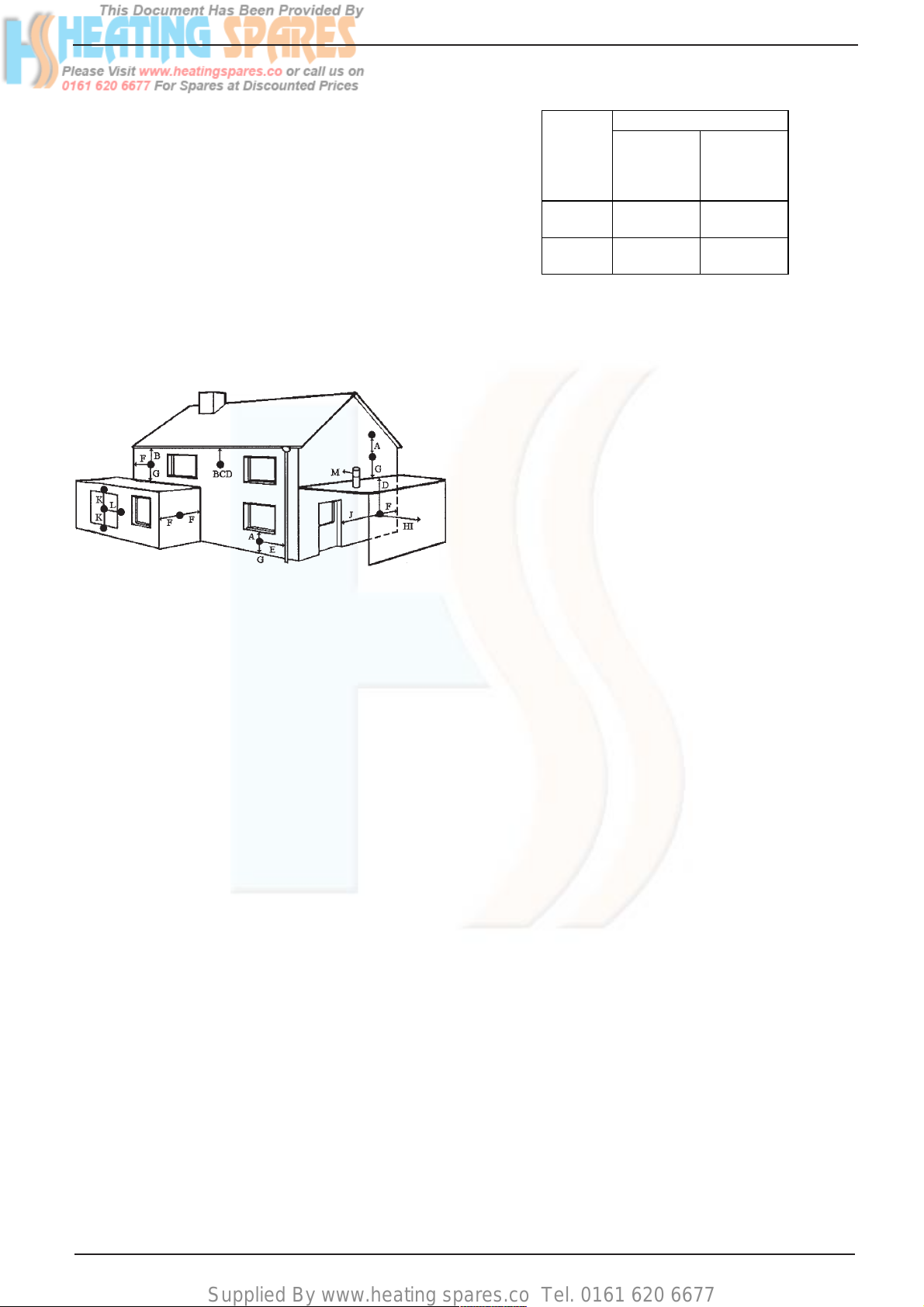
4.4 Flue System
The terminal should be located where
dispersal of combustion products is not
impeded and with due regard for the damage or discoloration that might occur to
building products in the vicinity (see fig 4).
The terminal must not be located in a place
where it is likely to cause a nuisance.
In cold and/or humid weather water vapour
may condense on leaving the flue terminal.
The effect of such steaming must be
considered.
Linea Max
5
Page 10
Supplied By www.heating spares.co Tel. 0161 620 6677
For protection of combustibles, refer to BS
5440:1 where the terminal is less than 2m
(6.6ft) above a pavement or platform to
which people have access (including any
balcony or flat roof the terminal must be
protected by a guard of durable material).
A suitable guard is available from Vokéra
Ltd. Part No 018, G.C. No. 301 106
This guard must be fitted centrally over the
terminal. Mark the positions of the fixings,
drill the wall and secure using wall plugs and
3 of 1½" No.8 plated screws.
Fig. 4
Terminal position for fan assisted boiler
(minimum distance) mm
A - Directly below an open window or other 300
opening (e.g. air brick)
B - Below gutters, soil pipes or drain pipes 25
C - Below eaves 25
D - Below balconies or car port roof 25
E - From vertical drain pipes and soil pipes 75
F - From internal or external corners 25
G - Above ground or below balcony level 300
H - From a surface facing a terminal 600
I - From a terminal facing a terminal 1200
J - From an opening in the car port (e.g. door
window) into dwelling. 1200
K - Vertically from a terminal on the same wall 1500
L - Horizontally from a terminal on the same wall 300
M - Horizontally from a vertical terminal to a wall 300
NOTE: The flue must be terminated in a place not likely
to cause a nuisance.
4.5 Air Supply
The following notes are intended for general
guidance.
The room sealed fan flued boiler does not
require a permanent air vent for combustion
air supply.
Where installed in a cupboard or compartment ventilation is required for cooling.
The table following gives the recommended
minimum effective areas of such air vents.
Air Vent areas
Positions
of
Air Vents
High
Level
Low
Level
Air From
Room or
Internal
Spaces
310 cm
2
48 in
310 cm
2
48 in
2
2
Air Direct
From
Outside
155 cm
2
24 in
155 cm
2
24 in
2
2
4.6 Water Circulation (Central Heating)
Detailed recommendations are given in
BS 6798:1987 and BS 5449:1:1990 (for
smallbore and microbore central heating
systems).
4.6.1 The following notes are given for general
guidance.
4.6.2 Pipework
Copper tubing to BS 2871:1:1971 is recommended for water pipe. Jointing should be
either by capillary soldered or with compression fittings.
Where possible, pipes should have a gradient to ensure air is carried naturally to air
release points and water flows naturally to
drain taps.
It should be ensured as far as possible that
the appliance heat exchanger is not a
natural collecting point for air.
Except where providing useful heat, pipes
should be insulated to prevent heat loss and
to avoid freezing. Particular attention should
be paid to pipes passing through ventilated
spaces in roofs and under floors.
4.6.3 By-Pass
An automatic by-pass is incorporated in the
boiler, but systems should be designed to
ensure that with all radiators turned off a
flow rate of at least 350 litres/hour (1.28
gals/min) is achieved through the system.
See 6.9.4
4.6.4 System Design
Vokèra Ltd recommend a 2-pipe system. Single pipe systems are more liable to be troublesome unless carefullly designed and installed.
4.6.5 Draining Taps
These must be located in accessible positions to permit the draining of the whole
system. The taps must be at least 15mm
nominal size and manufactured in accordance with BS 2879:1980.
6
Linea Max
Page 11
Supplied By www.heating spares.co Tel. 0161 620 6677
4.6.6 Air Release Points
These must be fitted at all high points where air
will naturally collect, and must be sited to
facilitate complete filling of the system.
4.6.7 The appliance has an integral sealed expansion vessel to accommodate the increase of
water volume when the system is heated. It
can accept up to 10 litres (2.2gals) of expansion water. If the appliance is connected to a
system with an unusually high water content.
Calculate the total expansion and add additional sealed expansion capacity as appropriate.
In general, modern systems will present no
problem.
4.6.8 Filling Point
A method for initially filling the system and
replacing water lost during servicing is provided on the appliance.
In the event that this method is not suitable in
a particular area, contact the local authority for
preferred methods.
4.7 Electrical Supply
The appliance is supplied for operation on
230V ~ 50Hz electricity supply. It should be
protected with a 3-amp fuse.
THIS APPLIANCE MUST BE EARTHED.
The method of connection to the mains electricity must allow complete isolation from the
supply.
The preferred method is by using a fused
double pole switch with a contact separation of
at least 3mm.
The switch must supply ONLY the appliance
and immediate electrical control circuits (e.g.
programmer / room thermostat)
Alternatively, use an unswitched shuttered
socket outlet with a fused 3-pin plug both
complying with BS 1363.
4.8 Showers
If a shower control is to be supplied from the
combination unit it should be of the type which
incorporates a thermostatic control and by
design is suitable for use with a combination
boiler. Check application with shower manufacturer.
4.9 Timber framed buildings
If the appliance is to be fitted in a timber framed
Building, it should be fitted in accordance with
the Institute of Gas Engineers publication (IGE/
UP/7) Guide for Gas Installations in Timber
Frame Buildings.
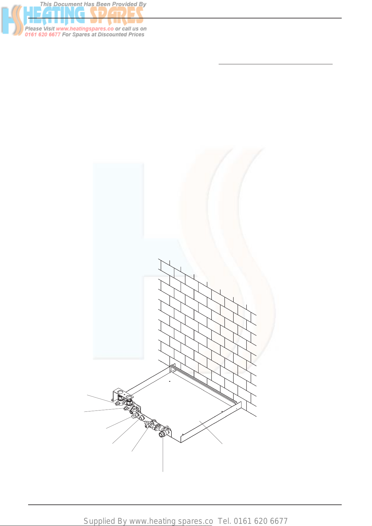
C/H Return
Valve
C/H Flow
Valve
Hot Water
Outlet
Safety Valve
Outlet
Cold Water
Inlet Stopcock/
filling valve
Gas
Cock
Linea Max
Base Tray
Fig. 5
7
Page 12
Supplied By www.heating spares.co Tel. 0161 620 6677
SECTION 5 INSTALLATION
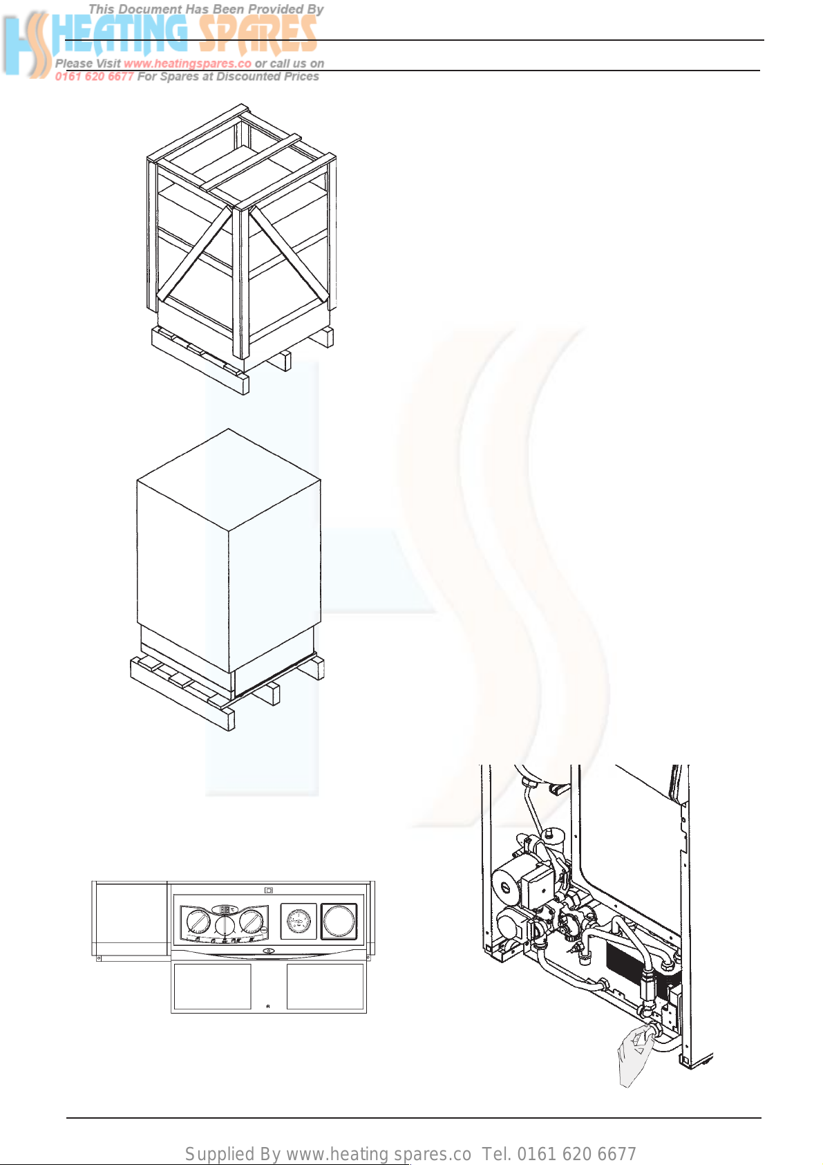
Fig. 6
Fig. 7
5.1 Delivery (fig. 6)
The appliance is delivered in a crated heavy
duty cardboard carton.
5.2 Unpacking (fig. 6 & 7)
Stand the boiler the correct way up and remove the surrounding timber frame.Slide the
protecting packaging from around the appliance. Remove appliance from base pallet.
The appliance comes complete with a base
tray which can easily be removed. The purpose of the base tray is that it can be used as
a template to preplumb the appliance before
final fitting.
To remove the base plate from the appliance,
push to release the control panel door, locate
the small tool inside and undo the two screws
securing the front panel to the appliance and
remove. Loosen and undo the Central heating
flow and return unions, cold water inlet union,
hot water outlet union, gas union and safety
valve union.See figs 5 & 9.
Ensure the filling inlet tap is in a horizontal
position. Either slide the base plate out from
the rear of the appliance or slide the appliance
forwards off the base plate. The appliance is
on wheels easing this operation.
The Base Tray Contains:
Central heating valves (2)
Gas service tap (1)
Cold water Filling/Inlet (1)
Hot water outlet Connection (1)
Found packed inside the appliance:
Safety valve outlet pipe (1)
Filling loop hose (1)
Various washers
Base plate screws (2)
Spare front panel door tool (1)
Restrictor ring (1)
Fig. 8
8
Flue kit supplied in separate carton.
Fig. 9
Linea Max
Page 13
Supplied By www.heating spares.co Tel. 0161 620 6677
Fig. 10
Fig. 11a
Rear pipework
reference bar.
Base tray securing screws
Fig. 11
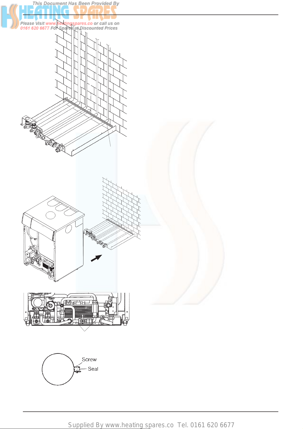
5.3 Siting the Appliance
5.3.1 The appliance is floor standing. Place the
base plate on a smooth firm and level surface.
The back of the base tray can be pushed flush
against the back wall if necessary (this will still
allow piping behind the appliance see figs 5
&10). Special floor protection is not required
and the floor must be capable of supporting
the weight of the appliance See section 3..
If the appliance is to be fitted in a timber
framed building it should be fitted in accordance with the Institute of Gas Engineers publication (IGE/UP/7) 'Guide for Gas Installations in Timber Frame Buildings'.
5.3.2 If necessary drill holes through the wall to
allow passage of pipework before final base
plate fixture see fig 10.
5.3.3 Drill and plug the floor for 4 - 1" No. 10 screws
and screw the base tray firmly into position
using rust proof countersunk screws.
5.3.4 Refer to figs.13 for relevant dimensions for
locating the flue hole: Where it is remote from
the boiler take special care to ensure hole is at
the correct level. Drill a 105mm hole through
the wall to allow passage of the flue pipe.
5.3.5 Connecting the Gas and Water
5.3.6 Figs. 5 and 13 show the locations of the
fittings.
5.3.7 When connecting pipework to valves do not
over tighten nuts, use another spanner to
apply counter force to avoid damaging/
moving the valves/baseplate.
5.3.8 Gas Supply
Connecting the gas supply.
Connect a 15mm gas pipe to the gas
service tap and tighten the union nut securing the tap to the appliance.
Pipework from the meter to the appliance
must be of adequate size.
A minimum gas pressure of 20mb (8 in.
w.g.) must be available at the appliance
inlet at full flow rate. See section 3.
DO NOT use pipes of a smaller size than
the appliance inlet connection.
5.3.9 Central Heating
Connect the central heating pipework
(22mm o.d) to the respective valves, right
hand: flow, left hand: return, and tighten the
nuts.
5.3.10 Hot Water
Connect a 15mm pipe to the hot water
outlet connection of the appliance. Tighten
the nut.
If the hot water system does not include a
tap below the hot water outlet connection,
provide a suitable drain tap to permit
draining of the appliance hot water side
during servicing.
Fig. 12
Linea Max
9
Page 14
Supplied By www.heating spares.co Tel. 0161 620 6677
5.3.11 Cold Water
Connect a 15mm cold water service pipe to
the inlet stopcock of the appliance. Tighten
the nut.
If the cold water supply is liable to high
pressure or large pressure fluctuations, a
flow/pressure regulator should be fitted in
the supply pipe.
Should the appliance be subject to 'mains
knock' it would be advisable to install a non
return valve in the hot water outlet pipe to
prevent unnecessary activation of the
domestic flow switch.
5.3.12 Safety Valve Discharge
Connect a 15mm pipe to the discharge
outlet of the appliance.
The discharge should terminate facing
downwards outside the building in a position
where discharging (possibly boiling) water
will not create danger or nuisance; but in an
easily visible position.
5.3.13 Once all relevant pipework has been installed
and the flue hole has been cut,the appliance
can be slid into position.
If the filling inlet valve is in the off position
(verticaly up) remove the handle from the
valve (this will allow the appliance to slide into
position without fouling the component).
Stand the appliance in front of the base tray
See fig.11. and gently slide into position.
Tighten the nuts from the valves on the base
plate to the corresponding inlet/outlet connections on the appliance using the fibre washers
supplied.
Finally secure the appliance to the base tray
using the 2 screws provided. See fig.11a.
Fit the filling loop hose and safety valve outlet
pipe and replace the filling/inlet valve handle.
Alternatively before the appliance is positioned
the system and supplies can be filled and
pressure tested using the Vokèra pressure
test kit (part no. 401). Pressure test kit instructions supplied with kit.
Note: All pipework can be installed to run up
behind the appliance. Ensure that the pipes
pass behind the reference bar to prevent the
pipes fouling the appliance when it is pushed
into position. See fig. 10.
Remove the knock out panel in the top panel
for pipe clearance See fig.17.
Fig. 13
Fig. 14
10
Linea Max
Page 15
Supplied By www.heating spares.co Tel. 0161 620 6677
5.4 Installing the flue system
Care should be exercised when determining
the position of the appliance and route of the
flue system with respect to hidden obstructions such as pipes, cables, etc.
5.5 Fitting the flue
The top flue outlet permits both horizontal and
vertical flue applications to be considered,
alternatively, the Vokera twin flue system can
be utilised if longer flue runs are required.
5.5.1 Concentric horizontal flue
(For concentric vertical flue, see 5.5.2)
(For twin flue applications, see 5.5.3)
The appliance flue outlet elbow can be rotated
at 90º intervals on its vertical axis allowing the
flue system to exit the appliance casing at the
rear, to the left, & to the right. In addition the
flue may be extended from the outlet elbow in
the horizontal plane (see 3.4.4), however if the
flue is to be extended and/or additional bends
are to be fitted, a reduction must be made to
the maximum flue length (see table below).
Reductio n i n maximum flue
Bend
lenght for each bend
45° 0,5 metre
90° 1,0 metre
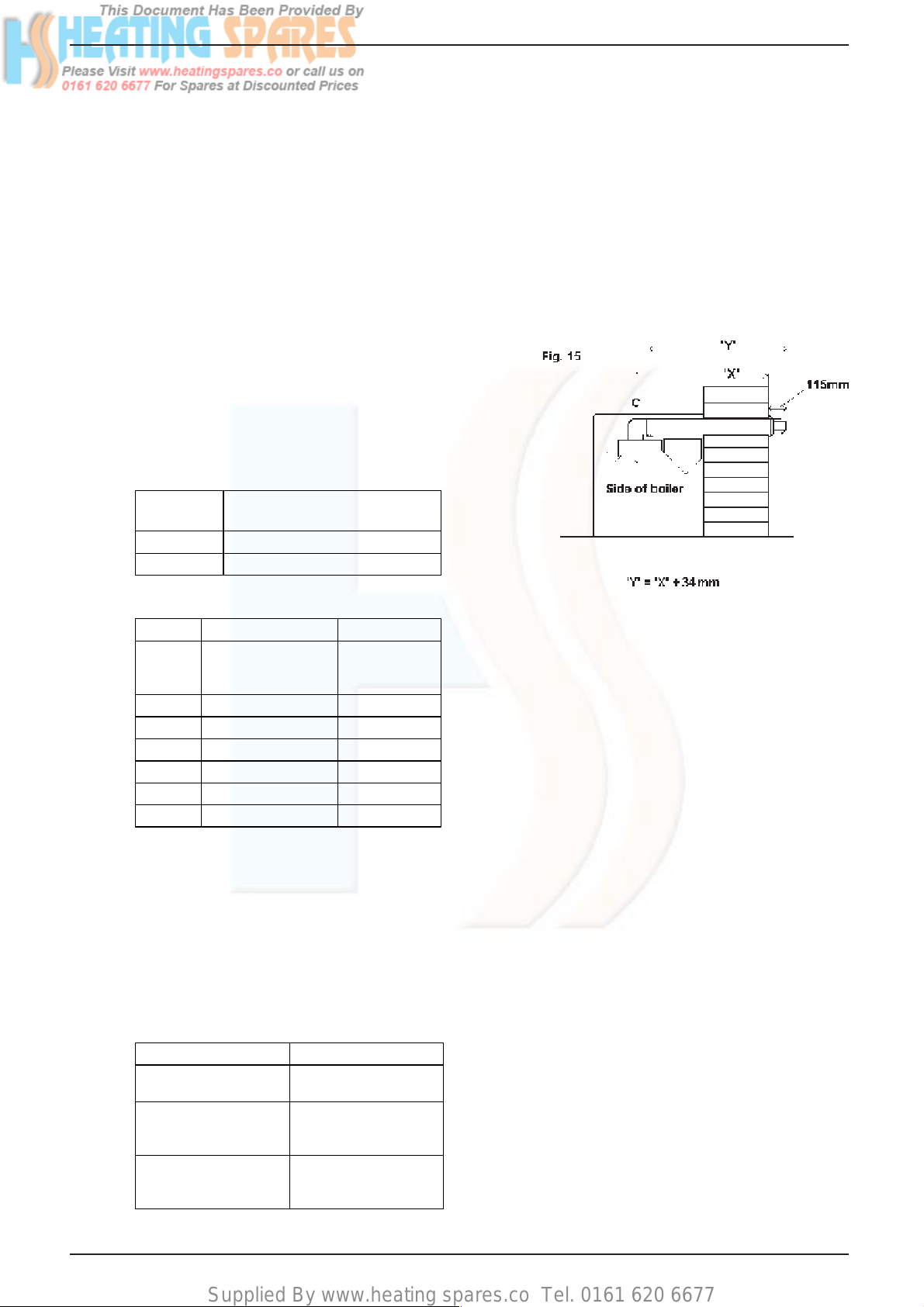
Discard the bend & inner (small) flue clip
supplied with the flue terminal.
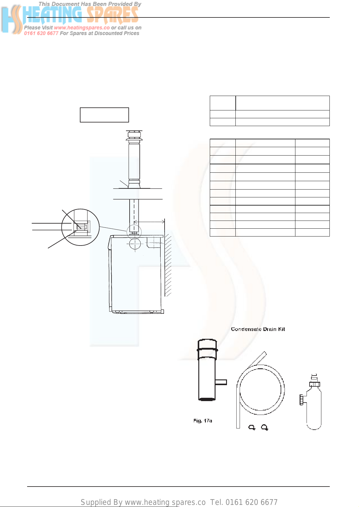
Carefully measure the distance from the centre of the appliance flue outlet to the face of the
outside wall (dimension X) and add 34mm to
give you dimension Y (see fig. 15).
Measure from the terminal end of the concentric flue pipe and mark off dimension Y. Cut
only the outer flue pipe at this mark.
Mark dimension Y on the inner flue pipe then
add 10mm and cut at the new mark.
This results in the inner flue pipe being 10mm
longer than the outer flue pipe.
Horizontal flue terminal and accessoires
Part No. Descrip tion Min-Max Length
0225700 Horizontal flue kit
For use with add.
Bends & exte nsio ns
0225755 Telescopic extension 35 0 - 500 m m
0225740 0,5 m extension 5 00 mm
0225745 1,0 m extension 1000 mm
0225730 45° bend (pair) N/A
0225735 901° bend N/A
0225760 Wall bracket (5) N/A
900 mm
Using the fig. 13 as a reference, mark and drill
a 115mm hole for the passage of the flue pipe.
The hole should have a 1º drop from the boiler
to outside, to eliminate the possibility of rainwater entering the appliance via the flue.
5.5.1.1 Standard horizontal flue (See 5.5.1.2 for
extending the horizontal flue)
The flue terminal (part no. 0225700) is suitable
for the following wall thickness:
Route Maximum wall thickness
Terminating to the rear 573mm (boiler hard
against rear wall)
Terminating to the left 509mm (boiler with
minimum clea ra nce a t
left hand side )
Terminating to the right 617mm (boiler with
minimum clea ra nce a t
right ha nd si de)
Insert the flue pipe into the previously drilled
flue hole.
Pull it towards the appliance flue bend and
insert the inner flue pipe into the push-fit socket
of the bend until the outer flue pipe butts
against the edge of the appliance flue bend.
Take the outer flue clip, seal, & screws (supplied with the flue terminal kit) and secure the
flue pipe to the appliance flue bend.
You must ensure that the entire flue system is
properly connected.
Check that the terminal protrudes past the
finished wall by the correct length (115mm).
Seal the flue assembly to the wall using cement or a suitable alternative that will provide
satisfactory weatherproofing. The exterior
trim can now be fitted.
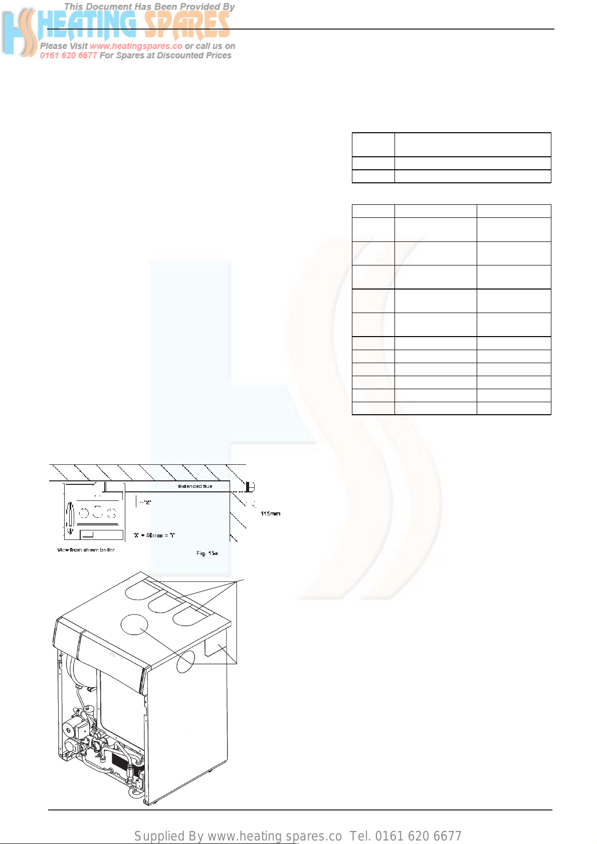
5.5.1.2 Extended horizontal flue
(see fig. 15a)
Discard the bend & inner (small) flue clip
supplied with the flue terminal.
Insert the flue terminal into the previously
drilled flue hole.
Connect the required bends and/or extensions
to the flue terminal working back towards the
boiler whilst maintaining a 1°fall (17mm per
1000mm) away from the boiler.
All bends and extensions are push-fit and
require no clips or screws, however care should
be taken to ensure that the correct seal is
made when assembling the flue system.
Linea Max
11
Page 16
Supplied By www.heating spares.co Tel. 0161 620 6677
Carefully measure the distance between the
appliance flue outlet bend and the 2nd last
extension or bend (dimension X). Add 40mm
to dimension X to give dimension Y (see fig.
15a).
Measuring from the socket end of the last
extension, mark and cut both pipes to suit
dimension Y.
Remove the appliance flue bend from the flue
outlet and insert the inner flue pipe of the
extension into the push-fit socket of the bend
until the outer flue pipe butts against the edge
of the appliance flue bend.
Take the outer flue clip, seal, & screws (supplied with the flue terminal kit) and secure the
flue pipe to the appliance flue bend.
Connect the assembled bend and extension to
the 2nd last extension or bend and ensure the
correct seal is made.
Finally connect the appliance flue outlet bend
to the appliance flue outlet.
NOTE
When cutting an extension to the required
length, you should ensure that the excess is
cut from the plain end of the extension. Remove any burrs, and check that both seals are
located properly.
You must ensure that the entire flue system is
properly supported and connected.
Seal the flue assembly to the wall using cement or a suitable alternative that will provide
satisfactory weatherproofing. The exterior
trim can now be fitted
Optional
knock-out
panels
Fig.16
5.5.2 Concentric vertical flue
(see fig. 16 & 16a)
The vertical flue terminal should be connected
directly to the appliance flue outlet. If additional bends and/or extensions are fitted, a
reduction must be made to the maximum flue
length (see table below & 3.4.4).
B end R eduction in maximum flu e le ngth for
each bend
45º bend 0.5 metre
90º bend 1.0 metre
Vertical flue terminal and accessories
Part No. Description Length
0225715 Vertical flue
terminal
0225770 Pitched roof
flashing plate
0225765 Flat roof flashing
plate
0225775 Vertical flue
connection kit
0225755 Telescopic
extension
0225740 0.5m extension 500mm
0225745 1.0m extension 1000mm
0225750 2.0m extension 2000mm
0225730 45º bend (pair) N/A
0225735 90º bend N/A
0225760 Wall bracket (5) N/A
IMPORTANT
The vertical flue terminal is 1.0 metre in length
and cannot be cut; therefore it may be necessary to adjust the position of the appliance to
suit or use a suitable extension.
Remove and discard the appliance flue outlet
bend.
Remove the knockout panel on the appliance
casing (directly above the appliance flue outlet).
Using the dimensions given in fig. 16a as a
reference, mark and cut a 105mm hole in the
ceiling and/or roof.
Fit the appropriate flashing plate to the roof
and insert the vertical flue terminal through the
flashing plate from the outside, ensuring that
the collar on the flue terminal fits over the
flashing.
Insert the boiler top adapter (supplied with the
vertical flue terminal) into the appliance flue
outlet ensuring the correct seal is made. Insert
the vertical flue assembly into the boiler top
adapter ensuring the correct seal is made. The
flue support bracket (supplied with the vertical
flue kit) can now be fitted.
If the vertical flue requires extension/s or additional bend/s, connect the required number of
flue extensions or bends (up to the maximum
equivalent flue length) between the boiler top
adapter and vertical flue assembly.
1.0 metre
N/A
N/A
N/A
350mm –500mm
12
Linea Max
Page 17
Supplied By www.heating spares.co Tel. 0161 620 6677
1 5
NOTE;
You must ensure that the entire flue system is
properly supported and connected.
When cutting an extension to the required
length, you should ensure that the excess is
cut from the plain end of the extension. Remove any burrs, and check that both seals are
located properly.
Fig. 16a
Y = 302 mm
Flashing Plate
Flue Outlet
Spigot
â
â
Collar
● Ensure that the entire flue system is ad-
equately supported, use at least one bracket
for each extension
● The entire flue system must be adequately
insulated to maintain heat within the flue
system thereby reducing the possibility of
condensate production.
● As the exhaust outlet pipe can reach very
high temperatures it must be protected to
prevent persons touching the hot surface.
B end R eduction in maximum flu e le ngth for
each bend
45º bend 1.0 metre
90º bend 1.0 metre
Twin flue accessories
Part No. Description Length
0225805 Horizontal flue terminal 1.0 metre
319 Twin adapter kit N/A
0225815 C ondensate drain kit N/A
0225820 0.25m extension (pair) 250mm
0225825 0.5m extension (pair) 500mm
0225830 1.0m extension (pair) 1000mm
0225835 2.0m extension (pair) 2000mm
0225840 45º bend (pair) N/A
Y
0225845 90º bend (pair) N/A
0225850 Twin bracket (5) N/A
0225855 S i ngle bracket (5) N/A
Air Inlet
Spigot
5.5.3 Twin flue system
The Vokera twin flue system enables greater
flue distances to be achieved (see 3.4.4) than
that of the standard concentric flue system,
however the twin flue system must be converted to the dedicated concentric flue kit for
termination. It is essential that the installation
of the twin flue system be carried out in strict
accordance with these instructions.
GUIDANCE NOTES ON TWIN FLUE INSTALLATION
● The flue must have a fall back of 1º back to
the appliance to allow any condensate that
may form in the flue system to drain via the
condensate drain. Consideration must also
be given to the fact that there is the possibility of a small amount of condensate dripping
from the terminal.
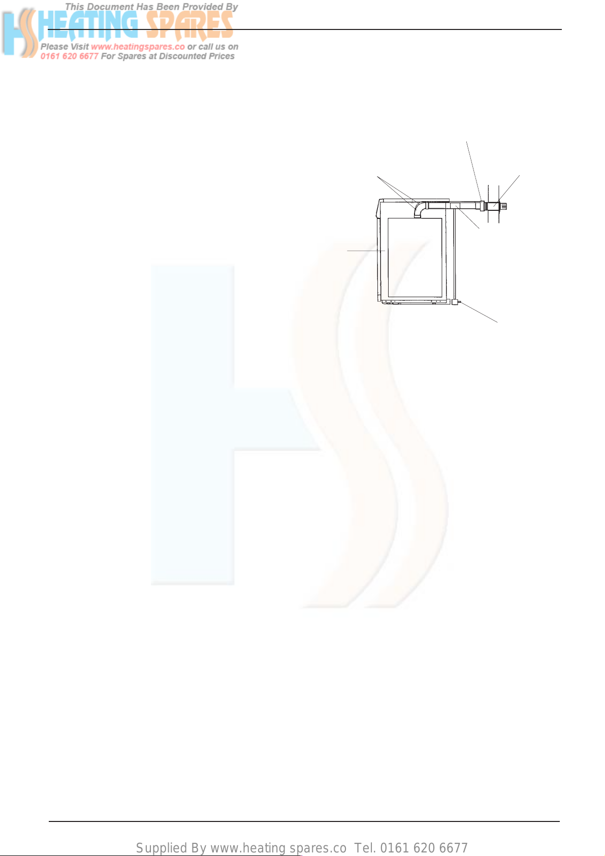
5.5.3.1 Installation of twin adaptor kit (fig. 17)
● Insert the exhaust connection manifold onto
the appliance flue outlet.
● Place the silicone seal (supplied with twin
adapter kit) over the rim of the exhaust
connection manifold.
● Remove one of the blanking plates (located
to the left & right of the appliance flue outlet)
and using the same screws install the air
baffle.
Linea Max
13
Page 18
Supplied By www.heating spares.co Tel. 0161 620 6677
5.5.3.2 Installation of condensate drain kit (fig. 17a)
The condensate drain kit must be fitted within
1 metre of the appliance flue outlet. It is
recommended that the condensate drain kit
should be fitted in the vertical plane, however
it can be fitted horizontally with care.
● Fit the first bend to the condensate drain kit
or exhaust connection manifold by firmly
pushing in to position.
● Using the two holes in the exhaust connec-
tion manifold as a guide, drill a 3mm hole in
each and secure using the screws provided.
● Connect the air inlet pipe to the air baffle as
above.
● The twin flue pipes extensions and accesso-
ries can now be installed by pushing together (the plain end of each extension or
bend should be pushed approximately
50mm into the female socket of the previous
piece).
5.5.3.3 Horizontal termination (See fig. 17c)
The twin flue system must be converted to the
dedicated concentric flue kit for termination.
● The horizontal terminal is supplied with a
built-in converter box and cannot be shortened.
● A 130mm hole is required for the passage of
the concentric terminal through the wall.
Depending on site conditions it may be preferable to install the terminal assembly prior to
fitting the twin flue pipes.
Mark and drill a 130mm hole for the passage of
the horizontal flue terminal, ensuring that there
is a 1º fall back to the boiler (17mm per
1000mm). Insert the terminal assembly into
the flue hole.
Push-fit the twin flue pipes onto the concentric
to twin converter box ensuring that the exhaust
pipe connects to the exhaust connection on
the concentric to twin converter.
If necessary cut the plain ends (male) of the
twin flue pipes to allow connection to the
concentric to twin converter.
NOTE; before cutting twin flue pipes ensure
allowances have been made for connection
onto the previous piece and onto the concentric to twin converter. The last twin flue pipes
must be pushed 50mm onto the male spigots
of the concentric to twin converter.
NOTE;
You must ensure that the entire flue system is
properly supported and connected.
The condensate drain trap must be connected
to the drain in accordance with building Regulations or other rules in force.
When cutting an extension to the required
length, you should ensure that the excess is
cut from the plain end of the extension. Remove any burrs, and check that both seals are
located properly.
Seal the flue terminal assembly to the wall
using cement or a suitable alternative that will
provide satisfactory weatherproofing. The interior and exterior trim can now be fitted.
Twin Flue system
Boiler
Fig. 17c
Concentric to Twin Converter
(Part no 310)
Horizontal
Flue Terminal
Condensate drain kit
Condensate trap
14
Linea Max
Page 19
Supplied By www.heating spares.co Tel. 0161 620 6677
5.5 Electrical Connections
5.5.1 The electricity supply must be as specified
in clause 4.7. If controls external to the
appliance are required, design of the external electrical circuits should be undertaken
by a competent person.
See Section 10 for further advice.
N.B. IT IS ESSENTIAL THAT ALL EXTERNAL CONTROL CIRCUITS AND WIRING IS
WIRED FROM THE SAME ELECTRICAL
ISOLATOR AS SERVES THE APPLIANCE.
Factory fitted internal wiring must not be
disturbed when wiring external controls.
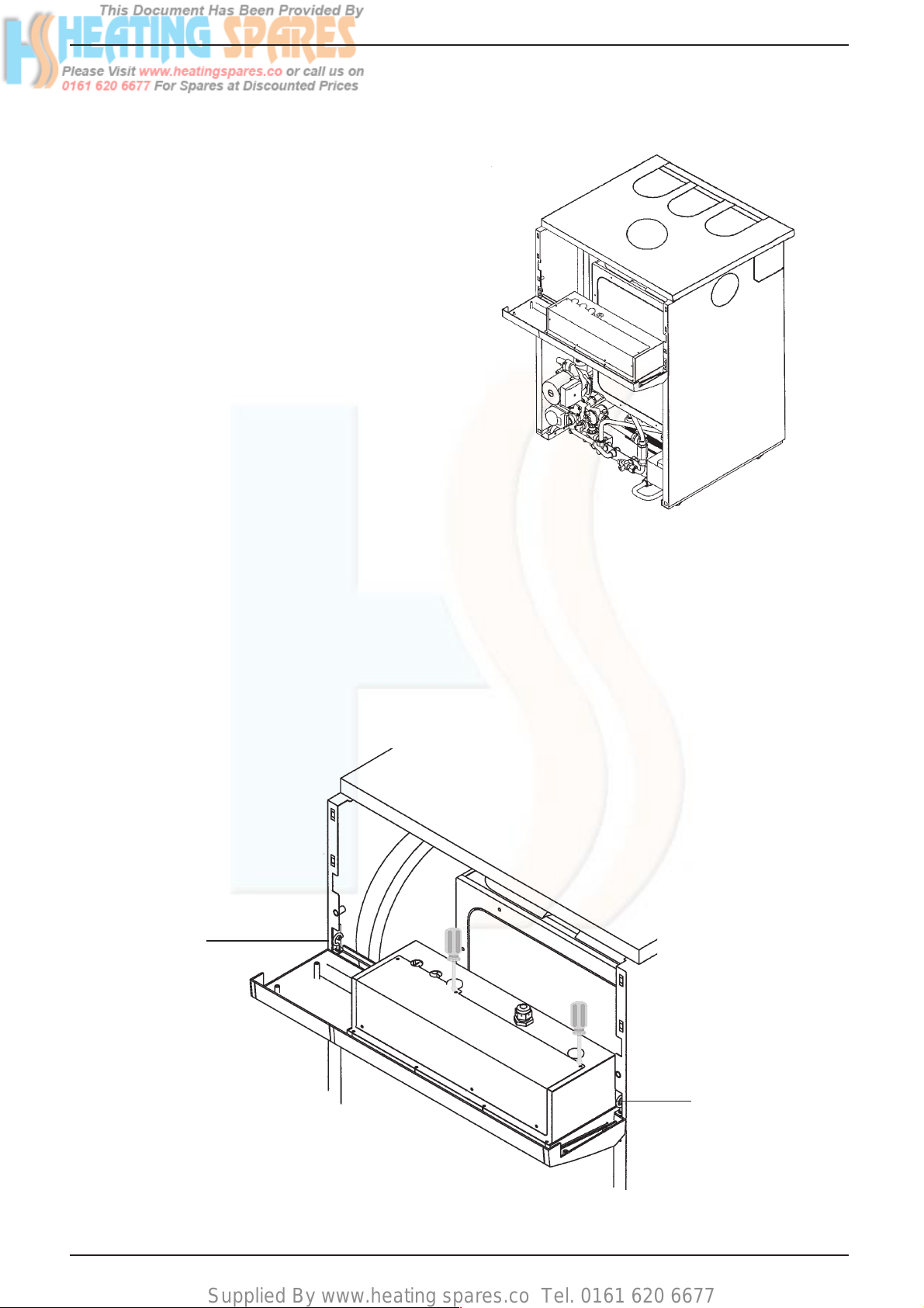
5.5.2 To gain access to the electrical terminals
Reposition front control panel by first pulling
it free from 4 locating lugs. Rotate the panel
through 90° degrees and relocate it into the
lower position using the locating hooks as
shown in fig.18 & 19.
Remove electrical cover by releasing nine
securing screws. Fig.19.
The mains input terminal block is now easily
visible (marked 1 - 6).
5.5.3 The electricity supply cable from the isolator
and the appliance terminal block must be 3
core flexible sized 0.75mm² (24 x 0.2mm) to
table 15-16, BS6500.
Wiring to the appliance should be rated for
operation in contact with surfaces up to
90°C.
Fig. 18
Locating hook
Linea Max
Locating hook
Fig. 19
15
Page 20
Supplied By www.heating spares.co Tel. 0161 620 6677
5.5.4 Pass the cable through one of the cord
anchorage points and connect the wires
Brown to L1, Blue to N, and Green/Yellow to
W of the terminal strip. Arrange the cable so
that should the cable slip the anchorage the
current carrying conductors become taut
before the earthing conductor.
5.5.5 Securely tighten all terminal screws and
arrange the cable with slack between the
cable anchor and the terminal block. Tighten
the cord anchorage screw until the cable is
secure.
5.5.6 Neatly arrange the external cable in such a
way that unrestricted opening of the controls
fascia and repositioning is possible without
strain on the cable.
5.5.7 External controls may be wired from terminals 1 & 2 or 2 & 3 after removing the
factory fitted link (between 2 & 3) depending
on wiring configuration (see pages 48 - 51
for further details). If a neutral is needed use
the terminal marked N on the terminal strip.
DO NOT CONNECT ANY WIRES TO THE
PRINTED CIRCUIT BOARD TERMINALS.
Section 10 gives details of fitment for external and internal controls (ie Vokèra time
clock).
If required pass the external controls cable
through the spare cord anchorage and
arrange the cable so that should the cable
slip the anchorage the current carrying
conductors become taut before the earthing
conductor.
Main Burner
Test Point
Incoming Gas
Pressure Test
Point
Fig. 20
Filling
Position
16
Closed
Position
Normal
Operating
Position
Fig. 21
Linea Max
Page 21

Supplied By www.heating spares.co Tel. 0161 620 6677
SECTION 6 COMMISSIONING
6.1 Where the text bears identifying numbers in
brackets, refer to figs. 1 and 2 unless
otherwise instructed.
6.2 Gas Supply Installation
Inspect the entire installation including the
meter. Test for soundness and purge, all as
described in BS6891:1988.
6.3 Central Heating Systems
6.3.1 IMPORTANT DO NOT RELEASE AIR
FROM THE RED SEALED EXPANSION
TANK. It is charged with air at the factory
from .75 - .80 bar (11 - 12psig)
6.3.2 Initial filling of the System
6.3.2.1 See 3.4.3.
6.3.2.2 Open central heating flow and return valves.
Unscrew black cap on automatic air release
valve (26) one full turn. (Leave open permanently).
6.3.2.3 Close all air release taps on the central
heating system.
6.3.2.4 Identify the filling/inlet valve found at the
base of the appliance. See fig.5.
The filling loop may have been disconnected
from the filling/inlet valve and heating flow
valve. If so reconnect unscrewing the caps
as necessary.
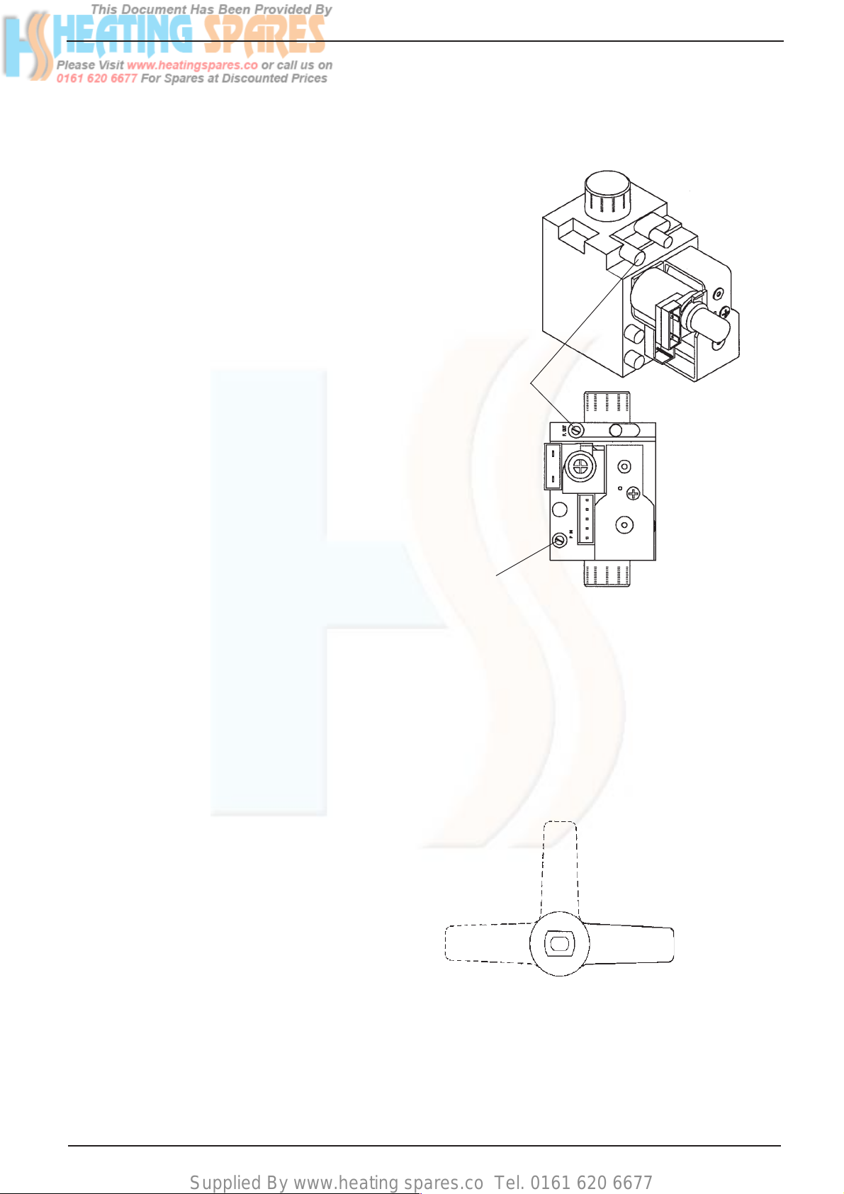
The filling/inlet valve has 3 positions. (Fig.
21) i) Vertically up - closed position.
ii) Turn to the left to horizontal - filling
position.
iii) Turn to the right to horizontal - normal
operating position.
To fill, slowly turn the handle of the filling/
inlet valve from the closed position towards
the filling position. Mains water will be heard
to enter the system/boiler. As the water
enters the system/boiler the pressure gauge
will be seen to rise. Pressurise to between
1bar & 1.5bar when the system is cold. DO
NOT OVERPRESSURISE.
Once the desired pressure is achieved turn
the filling/inlet valve back to the closed
position.
6.3.2.5 Starting with the lowest radiator open each
air release tap in turn closing it only when
clear water, free of bubbles, flows out. In the
same away release air from any high points
in the pipework.
6.3.2.6 Continue filling the system until at least 1.0
bar registers on the gauge then turn the
handle of the filling/inlet valve back to the
closed position.
6.3.2.7 Inspect the system for water soundness and
remedy any leaks discovered.
6.3.3 Initial Flushing of the Pipework
The whole of the heating system must be
flushed both cold and later hot as detailed in
6.10.1. Open all radiator or heating valves
and the appliance central heating valves.
Drain the boiler and system from the lowest
points. Open the drain valve full bore to
remove any installation debris from the
boiler prior to lighting. Refill the boiler and
heating system as described in 6.3.2.
6.3.4 Setting the System Design Pressure
6.3.4.1 The design pressure should be a minimum
of 1 bar and maximum 1.5 bar.
6.3.4.2 The actual reading should ideally be 1 bar
plus the equivalent height in metres to the
highest point of the system above the base
of the appliance. (Up to the maximum of 1.5
bar total).
N.B. The safety valve is set to lift at 3bar/
30m / 45psig.
6.3.4.3 To lower the system pressure to the required value, pull the lever on the head of
the safety valve to release water until the
required figure registers on the gauge.
6.3.5 Filling the Hot Water System
6.3.5.1 Close all hot water draw-off taps.
6.3.5.2 Turn filling/inlet valve to the normal operat-
ing position (horizontally to the right). See
fig.21
6.3.5.3 Slowly open each draw-off until clear water
is discharged.
6.4 Checking Electricity Supply
6.4.1 Carry out preliminary checks for continuity,
polarity, and resistance to earth (see page
61), gaining access as required according to
5.5.2 in this manual.
6.4.2 Leave the appliance with the control fascia
open and with the mains electricity switched
OFF
6.5 Lighting the Boiler
6.5.1 Ensure flow and return valves are open.
If external and/or internal controls are fitted
(e.g Timeclock and/or Room thermostat)
ensure they call for heat. The commissioning of the appliance may be easier if the
external/internal controls are disconnected
and terminals 2 & 3 are linked. (For access
procedure turn off electricity and refer to
5.5.2 for instructions).
6.5.2 Switch on the mains electricity and turn the
on / off / mode switch to
6.5.3 Set the c/h control knob to the highest
setting.
6.5.4 The pump only will run for approximately 1
minute, the appliance will then go through
an ignition sequence and the burner will
light.
Linea Max
17
Page 22

Supplied By www.heating spares.co Tel. 0161 620 6677
6.5.5 If during the ignition attempt period (10 secs
approx.) the boiler fails to light, the ignition
control circuit will go to lockout. This is
indicated by the status LED flashing red
accompanied by a flashing error code 01
shown in the temperature indicator. The gas
valve is de-energised, but leaves the fan
and pump running for approximately 2
minutes after lockout.
6.5.6 In the event of the boiler going to lockout
turn the mode selector switch to the reset
position for approximately 10 seconds, then
back to the original position. The two main
causes of the boiler going to lockout during
commissioning are electrical supply polarity
reversed, or air in the gas supply. Check
polarity and that the gas supply is completely purged of air, and that gas is reaching the
boiler, then repeat from 6.5.2.
6.6 Checking Burner Pressures
6.6.1 The heat inputs for high and low gas rates
are factory set to the maximum values given
in section 3.6 for domestic hot water and
central heating but it is necessary to check
them when commissioning.
6.6.2 Turn off the main electricity supply. Gain
access to the interior by removing front door
panel.
6.6.3 Locate the main burner pressure test point
(Fig. 22) and slacken the screw half a turn in
an anti clockwise direction. Attach a suitable
U gauge tube between the test nipple and
manometer (see fig. 22).
IMPORTANT: Before measuring gas pressures it is imperitive that the protective
cover over the gas valve adjustment screw
is removed. (Fig. 33)
Turn on electricity supply and fully open a
domestic hot water tap to operate boiler in
dhw mode. Adjust hot water control knob to
it's maximum setting.
6.6.4 The pressure reading for maximum rate
should be:
10.1mbar
(plus or minus 1.0mbar)
If the pressure is wrong it should be adjusted as instructed in 8.23 (N.B. Whenever
the maximum rate is adjusted check and
adjust the minimum rate too)
6.6.5 Reduce the domestic water flow rate to
approx. 3-4 litres/min, turn the domestic
control knob slowly to minimum. The boiler
output will reduce to the minimum setting. If
low flame cannot be established in this way,
turn off the electricity supply and remove
one of the grey wires connecting to the
modulator coil on the front of the gas valve.
Switch on the electricity supply. The boiler
will now light at the minimum setting.
6.6.6 When low flame is established, the pressure
reading should be:
1.3mbar
(plus or minus 0.13mbar)
If it is different adjustment should be made
in accordance with the instructions in 8.23.
6.6.7 If the grey wire from the modulator coil was
removed to check the minimum setting, turn
off the electricity supply and replace the wire
onto the modulator coil.
Main burner test point
Gas Valve
Manometer
18
U Gauge Tube
Fig. 22
Linea Max
Page 23

Supplied By www.heating spares.co Tel. 0161 620 6677
6.6.8 Setting the Maximum Rate for Central
Heating
The maximum heat input for the central
heating mode is not adjustable.
6.7 Checking the Flue System
6.7.1 The flue system should be visually checked
for soundness. Check all clamps and fixings
are secure and tight.
6.8 Checking the Heating Thermistor
6.8.1 Allow the system to warm up and manipu-
late the c/h control knob to ensure that the
burner modulates between high and low
and then to off and vice versa (scale range
covers approx. 45° - 85°C).
6.9 Regulating the Central Heating System
6.9.1 Fully open all radiator and circuit valves and
run the appliance in the central heating
mode until heated water is circulating. If
conditions are warm, remove any thermostatic valve heads.
6.9.2 If the burner will not light, ensure that water
is in fact circulating. See 4.6.3.
6.9.3 Adjust radiator return valves and any branch
circuit return valves until the individual
return temperatures are correct and are
approximately equal.
6.9.4 When all is adjusted, progressively close all
radiator valves to ensure that the appliance
still operates when flow through the system
is limited.
If the burner cuts out prematurely due to
lack of water flow through the appliance, the
system should be regulated to ensure a flow
rate of at least 350 litres/h (78 gals/h). This
may mean the addition of a small manual
by-pass being fitted to the system if a fully
TRV system is used.
6.10 Final Flushing of the Heating System
6.10.1 The system should be flushed in accord-
ance with BS7593:1992. Turn on the boiler
for central heating and allow the boiler and
system to reach temperature. Turn off the
boiler and drain the system whilst hot.
Refill the boiler and heating system as
described in 6.3.3.
Although not necessary for correct operation
of the boiler an inhibitor may be added at
this point. Contact the inhibitor manufacturer
for further information concerning application and required dose.
6.10.2 Inspect the system for soundness. Turn the
appliance off at the mode selector switch.
6.11 Filling, Testing and Regulating the
Domestic Hot Water System
6.11.1 Start with the appliance switched on having
completed the procedures described in 6.4
to 6.10.
6.11.2 Open a domestic hot water tap (Preferably
the bath tap).
Ensure cold water inlet stopcock is fully
open (horizontally to the right) and the dhw
control knob is set at maximum.
6.11.3 The flow of water should activate the domestic hot water flow switch (13) and drive
the diverting valve (21) to its hot water
position thus heating the domestic water
flowing through the dhw heat exchanger. At
the same time the pump and fan are activated lighting the burner on maximum rate.
6.11.4 If the burner does not light, check that the
water flow rate is above the minimum
required to operate the domestic hot water
flow switch (13) 2.0 litres/min (0.45 gals/
min).
6.11.5 The temperature of the water will depend on
the rate at which it flows and the amount of
energy stored in the primary store.
The temperature of water at the tap can be
varied by adjusting the water flow rate at the
tap up to the maximum predetermined
quantity.The hot water temperature control
knob will govern the maximum temperature.
When the appliance is being used in hot
water mode the temperature indicator
indicates the temperature of the hot water
leaving the appliance.
6.11.6 It is best to set for the lowest acceptable
temperature since the user can gain higher
temperatures by restricting flow at the tap.
N.B. If the cold supply is subject to large
fluctuations or is above the permitted maximum a suitable pressure/flow regulator
should be fitted in the cold water supply to
the appliance.
6.11.7 Turn the appliance mode selector switch to
the position.
Slowly close the tap to reduce the rate of
draw to above the minimum approx. 2.0
litres/min., (0.45 gal/min.) Rotate the dhw
control knob to ensure the appliance modulates at its various setting.
6.11.8 Close the draw-off tap still further. The
burner should stop when the rate falls below
approximately 2.0 litres/min. (0.45 gal/min.),
and the primary store temperature is replenished.
6.11.9 The appliance incorporates a hot water
preheat facility. The appliance will therefore
ignite periodically to maintain heat within the
thermal store of the appliance.
6.12 Final Check for Operations
Turn mode selector switch to the OFF/
RESET position, disconnect pressure
gauge, re-tighten screw. Relight boiler.
6.12.1 Re-check for gas soundness
6.12.2 Re examine heating and hot water systems
and cold water supply for water soundness.
6.12.3 Check the appearance of the gas flame to
assess adequacy of combustion air supply.
Linea Max
19
Page 24

Supplied By www.heating spares.co Tel. 0161 620 6677
6.12.4 Re-check the flue system for soundness and
adequacy of supports.
6.13 Concluding Operations
6.13.1 If external/internal controls have been
disconnected and terminals 2 & 3 temporarily linked, remove the link and reconnect the
controls circuit. Check the operation of the
controls.
6.14 Disconnect filling loop, fit filling loop cap.
Leave filling loop in a safe and accessible
place.
6.14.1 Reposition the front control panel and fit the
front boiler casing panel (fig. 18).
SECTION 7 INSTRUCTING THE USER
6.15 Supplementary Instructions for Fitting &
Removing Optional Time Clock and for
Wiring to External Controls.
Section 10 Appendices A and B at the rear
of this manual provides full instruction for
fitting and wiring the optional built-in time
switches and for wiring to external controls.
6.16 Complete details of the boiler, controls,
installation and commissioning in the log
book supplied with the boiler. This is an
important document which must be correctly
completed and handed to the user. Failure
to install and commission this appliance to
the manufacturers instructions may invalidate the warranty.
7.1 Hand over the copy of the Users Instructions
and the boiler log book supplied with the
appliance, together with these instructions.
Explain how to operate the boiler correctly
and how to use the timeclock and room
thermostat if fitted.
7.2 Show the user how to switch off the appliance and indicate the position of the electric
supply isolator.
7.3 Inform the user of the location of all drain
cocks and air vents.
SECTION 8 SERVICING INSTRUCTIONS
8.1 General
To ensure the continued safe and efficient
operation of the appliance, it is recommended that it is checked and serviced as
necessary at regular intervals.
The frequency of servicing will depend upon
the particular installation conditions and
usage, but in general, once per year should
be adequate.
It is the law that any servicing work is
carried out by a competent person such as
a Vokèra service engineer, approved
service agent, British Gas or other CORGI
registered personnel.
The following instructions apply to the boiler
and its controls, but it should be remembered that the central heating and domestic
hot water systems will also require attention
from time to time.
8.2 Important Notes
WARNING: Having carried out preliminary
flame checks and before starting any
servicing work, switch OFF the mains
electricity supply and disconnect the plug at
7.4 Explain how to turn the appliance off for both
short and long periods and advise on the
precautions necessary to prevent damage
should the appliance be inoperative when
freezing conditions may occur.
7.5 Show the user the filling loop position its
function and how to repressurise the system
using the filling/inlet valve.
7.6 Finally, advise the user that, for continued
safe and efficient operation, the appliance
must be serviced by a competent person at
least once a year.
the main isolating switch and socket. (If a
switch is used remove the fuse.)
Turn off gas supply at the gas service tap
fitted to the appliance.
Always test for gas soundness after any
service work and after exchanging any gas
carrying component.
8.3 Recommended Routine Servicing
8.3.1 Annual Servicing
When servicing is required the following
procedures should be carried out.
1. Inspect exterior for signs of damage and
deterioration, particularly of flue pipework
and electrical connections.
2. Turn off mains electricity and remove
front casing (see clause 8.4.).
3. Replace fuse if previously removed (8.2.
above) and turn on electricity. Run the boiler
for a few minutes in the domestic hot water
mode to permit inspection of its operation.
This is accomplished by opening a domestic
hot water draw off tap and inspecting burner
for yellowing of flame tip, flame lift off or
sooting.
20
Linea Max
Page 25

Supplied By www.heating spares.co Tel. 0161 620 6677
4. Ensure central heating valves are open.
See 6.3.2.1.
Observe pressure gauge reading (fig. 1, 19)
which should be approximately 1 bar when
the system is cold See 6.3.4
5. Turn off mains electricity and turn off gas
service tap on the appliance.
6. Gain general access as described in
clause 8.4.
7. Remove main burner (see clause 8.6).
Lightly clean with a soft brush and inspect
for damage. If during initial inspection any
combustion irregularity was suspected,
remove injectors and clean or replace (see
clause 8.7).
8. Place cloth below combustion chamber to
catch debris. Clean heat exchanger using
suitable brushes and rods if necessary.
9. Inspect combustion chamber lining. The
insulating material is easily damaged. Do
not scrape, but clean off lightly.
If any panels are damaged these should be
replaced (see clause 8.11).
10. Replace all parts in reverse order but
leave the controls fascia open and outer
casing off.
11. Undertake a complete commissioning
check as detailed in section 6.
12. Close up control fascia and refix front
casing.
13. Clean off casing using soft cloth and
dilute detergent.
14. Complete details of service undertaken
in the boiler log book.
NOTE: There is a flue gas analysis test
point incorporated in the flue outlet. (see
8.23.6)
8.3.2 Replacement of Parts
1. The life of individual components varies
and they will need servicing as and when
faults develop. The fault finding sequence
charts in section 9 will serve to locate which
component is the cause of any malfunction.
Instructions for removal, inspection and
replacement of the individual parts are given
in the following pages.
2. The domestic hot water heat exchanger
may in certain conditions become partially
blocked by scale deposits. Evidence of this
will be deterioration in performance.
This condition could well be treated using
proprietary descalants following makers'
instructions without dismantling the appliance by circulating a fluid through the dhw
coil. To do this, disconnection from hot and
cold services is necessary. Reconnect only
after thorough flushing with clean water.
3. Occasional maintenance of mechanical
working parts will be necessary (three port
valve, flow diaphragm). Service kits are
available from your local Vokèra stockists.
Vokèra Service Kit No.T0019
8.4 To Gain General Access/Assembly
To remove components access to the
interior is essential.
Ensure electricity supply is isolated before
carrying out any servicing.
8.4.1 To remove front casing.
Push to release front door panel and lower
to reveal controls. Found magnetised on the
inside of the door panel will be a small tool.
Using the tool loosen the 2 captive screws
securing the front control panel door to the
appliance, lift away to reveal the inside of
the appliance.
If necessary reposition the front control panel
by first pulling it free from 4 locating lugs.
Rotate the panel through 90° degrees and
relocate it into the lower position using the
locating hooks as shown in fig.18.
Fig. 23
8.4.2 Reassembly is always carried out in reverse
order to dismantling, unless otherwise stated.
Electrical connections must be remade in accordance with the wiring diagram (fig.36).
8.4.3 Where gas control components are replaced, check the burner pressures and
adjust if necessary. See 8.23.
8.5 Room Sealed Chamber Front Cover
Refer to fig. 23.
Flue gas analysis
test point
Linea Max
Fig. 24
21
Page 26

Supplied By www.heating spares.co Tel. 0161 620 6677
8.5.1 Gain general access as 8.4
8.5.2 Remove room sealed cover plate by releas-
ing two lower retaining clips and easing
cover off the top locating hooks. Inspect
gasket for damage. If damaged, replace.
NOTE: When refitting the combustion
chamber front cover it is essential to correctly seat and secure the cover in place
ensuring both clips are secured in place.
8.6 Main Burner and Spark Electrode
Part No's
Main Burner - 5317
Spark Electrode - 1931
Refer to figs. 25 & 26
8.6.1 Gain general access as 8.4.
8.6.2 Remove room sealed front cover as 8.5
8.6.3 Remove front of combustion chamber by
releasing six screws (fig. 24).
8.6.4 Remove four burner retaining screws (fig.
25). Ease burner forward and rest on
chamber base (fig. 26).
8.6.5 Release electrode and earth retaining
screws & carefully remove electrode.
8.6.6 Trace electrode and earth lead to electronic
ignition control and gas valve and disconnect.
8.6.7 Remove main burner.
8.6.8 Reassemble in reverse order ensuring
correct location of electrode, and solid
earthing point.
Note: If difficulty is found in relocating the
burner securing screws, easier access can
be gained by removing the two side panels
(fig. 26).
8.8.6 Turn the 3 butterfly primary store isolation
valves to the closed position (handle across
valve body) this isolates the primary store
thus preventing unnecessary draining.
8.8.7 Close heating flow and return valves by
turning ¼ turn until indicating lines are
horizontal. Pull lever on head of safety
valve to drain primary circuit to boiler.
8.8.8 Place cloth under heat exchanger to catch
surplus water.
8.8.9 Unscrew unions on either side of main heat
exchanger fig. 25.
8.8.10 Slide out main heat exchanger, taking care
not to damage insulation panels. Avoid
spillage of water on boiler electrics.
8.8.11 Reassemble in reverse order using new
fibre washers in unions.
Fig. 25
8.7 Main Burner Injectors
8.7.1 Gain general access as 8.4
8.7.2 Remove room sealed front cover plate and
combustion chamber front (8.5 & 8.6.3).
8.7.3 Remove main burner (8.6.4 to 8.6.8).
8.7.4 Unscrew injector(s) from burner bar.
8.8 Main Heat Exchanger
Part No. 28 - 1914
Refer to Fig. 25
8.8.1 Gain general access as 8.4
8.8.2 Remove room sealed front cover plate (8.5).
8.8.3 Remove front of combustion chamber
(8.6.3).
8.8.4 Remove two air baffle plates, 1 screw
securing each (fig.27).
8.8.5 Remove both side panels, 2 screws each
(fig.26)
Fig. 26
22
Linea Max
Page 27

Supplied By www.heating spares.co Tel. 0161 620 6677
8.9 Flue Fan
Part No. 5911
8.9.1 Remove room sealed front cover plate (8.5)
and front of combustion chamber (8.6.3).
8.9.2 Loosen maintenance clip securing screws
(see fig.27) and slide upwards to clear joint.
8.9.3 Remove silicone pipes from nozzles on
inner flue bend
8.9.4 Remove 3 flue hood retaining screws (see
fig. 27).
NOTE: When removing the two side screws
the two air baffle plates can be removed.
8.9.5 Carefully slide flue hood forward disconnecting electrical leads on fan in the process.
8.9.6 Unscrew 4 screws securing fan to flue hood
and remove fan. Transfer aluminium
manifold (two screws) to new fan.
8.9.7 Reassemble in reverse order, replacing
centre hood screw first.
8.10 Flue Pressure Differential Switch
Part No 9232
Refer to Fig. 27
8.10.1 Gain general access as 8.4
8.10.2 Remove room sealed cover (8.5)
8.10.3 Remove 2 screws holding pressure differen-
tial switch to the combustion chamber.
8.10.4 Pull off tab connectors and remove pressure
switch, disconnecting the air pressure pipes
in the process.
8.10.5 Reassemble in reverse order.
See fig. 36 for correct fitting of electrical
connections. When reconnecting the pressure pipes the upper nozzle on the inner
flue bend connects to the front nozzle of the
pressure differential switch.
8.11 Combustion Chamber Insulation Boards
8.11.1 Gain general access as 8.4
8.11.2 Remove room sealed front cover 8.5
Remove front of combustion chamber 8.6.3.
Remove Main Heat Exchanger 8.8.
8.11.3 To remove side combustion chamber
insulation boards, gently prise upwards and
pull out.
8.11.4 To remove rear board, gently prise upwards
and pull out.
8.11.5 Fourth panel (front) is replaced complete
with combustion chamber front panel.
Maintenance clip
Air
baffle
plate
Pressure
differential switch
Air
tubes
Air
baffle
plate
Fig. 27
Hood
Retaining
Screws
Linea Max
23
Page 28

Supplied By www.heating spares.co Tel. 0161 620 6677
8.12 Ignition Control Box
Part No. 099864
8.12.1 Gain general access as 8.4.
8.12.2 Release 1 screw (upper) securing ignition
box to gas valve body.
8.12.3 Disconnect electrode lead from ignition box.
8.12.4 Disconnect ignition control box from gas
valve by sliding out of situ.
8.12.5 Release one screw to release electrical
cover plate on ignition control box.
8.12.6 Remove internal electrical plug-in connector
by gently pulling and releasing.
8.12.7 Reassemble in reverse order ensuring
correct location of electrical plug and
electrode lead.
8.13 Gas Control Valve (complete)
Part No. 099862 fig. 28
8.13.1 Turn off gas service tap.
8.13.2 Remove Ignition control box as 8.12
8.13.3 Pull off silicone tube from gas valve regula-
tor.
8.13.4 Disconnect earth leads from gas valve.
8.13.5 Disconnect wires from modulator coil.
8.13.6 Unscrew gas service tap union & release
from its seating.
8.13.7 Undo union above the gas control valve &
withdraw gas valve.
8.13.8 Undo union from base of gas valve and
transfer supply tube to new gas valve.
8.13.9 Reassemble in reverse order.
8.13.10 Test all joints for gas soundness.
8.13.11 Check burner pressures. As 6.6
If incorrect adjust as instructed in 8.23.
Gas Valve Regulator
Silicon Pipe Connection
Point
Modulator
Coil
Pipe Securing Clip
Pump
Securing
Bracket
Fig. 28
24
Fig. 29
Linea Max
Page 29

Supplied By www.heating spares.co Tel. 0161 620 6677
8.14 Pump
Part No. 088031 Refer to fig.29
8.14.1 Gain general access as 8.4
8.14.2 Turn the 3 butterfly primary store isolation
valves to the closed position (handle across
valve body) this isolates the primary store
thus preventing unnecessary draining.
8.14.3 Close heating flow and return valves
(fig.30), by turning ¼ turn until indicating
lines are horizontal. Pull lever on head of
safety valve to drain primary circuit to boiler.
8.14.4 Place cloth under pump to catch surplus
water.
8.14.5 HEAD ONLY Unscrew the 4 allen screws
around the pump head. Pull head from base
of pump and disconnect electrical leads. If
replacement required, use the head from a
standard 15-60 Grundfos pump.
8.14.6 COMPLETE PUMP Disconnect pipe union
connection at front left corner of combustion
chamber.
8.14.7 Disconnect push fit pipe from pump body by
releasing pump securing clip and pulling
pipe free from body.
8.14.8 Remove screw from pump securing bracket.
8.14.9 Grasp pump and pull upwards with slight
twisting movement to release pump from
manifold.
8.14.10 Disconnect electrical leads from pump.
8.14.11 Reassemble in reverse order.
Reconnect electrical leads Brown to L, Blue
to N and Green to E.
8.15 Domestic Flow Switch
Refer to fig. 30.
8.15.1 Gain general access as 8.4.
8.15.2 Place receptacle or an absorbent pad below
switch to catch trapped water.
8.15.3 Close cold water inlet stopcock. See fig.30
8.15.4 Open lowest draw-off or drain tap on hot
water system.
8.15.5 Disconnect cold water inlet valve from flow
switch by undoing union.
8.15.6 Disconnect union at top of flow switch and
two electrical tab connectors.
8.15.7 Reassemble in reverse order.
8.16 Combined Diverter Valve & Flow Switch
Manifold
Refer to fig. 30
8.16.1 Gain general access as 8.4
8.16.2 Remove Pump as 8.14
8.16.3 Remove motorised valve as 8.21.8.
8.16.4 Release flow microswitch from the hydraulic
group by removing one retaining screw on
bracket.
8.16.5 Disconnect flow tube union and rear union
where they connect onto the hydraulic
group.
8.16.6 Disconnect expansion vessel pipe.
8.16.7 Unscrew pressure gauge connection retain-
ing screw and pull out pressure gauge
connnection.
8.16.8 Disconnect safety valve discharge pipe and
heating valve unions.
8.16.9 Remove retaining allen screw securing
hydraulic group to frame.
8.16.10 Withdraw hydraulic group from appliance.
See fig. 31 for further disassembly.
8.16.11 Reassemble in reverse order ensuring that
washers are replaced in all union connections.
Motorised Valve
Safety
Valve
Heating flow
and return valves
Diverter Valve
& Flow Switch
Assembly
Domestic
Heat
Exchanger
Linea Max
Domestic Hot
Water Flow Switch
Cold Water
Inlet Stopcock/
filling valve
Gas Valve
& Ignition Control
Box
Fig. 30
25
Page 30

Supplied By www.heating spares.co Tel. 0161 620 6677
8.17 Removal of Domestic Hot Water Heat
Exchanger
Refer to figs. 30
8.17.1 Gain General access 8.4
8.17.2 Place receptacle or an absorbent pad below
heat exchanger to catch trapped water.
8.17.3 Close cold water filling/inlet valve. See fig.
21
8.17.4 Open lowest draw-off or drain tap on hot
water system.
8.17.5 Turn the 3 butterfly primary store isolation
valves to the closed position (handle across
valve body) this isolates the primary store
thus preventing unnecessary draining.
8.17.6 Close heating flow and return valves (fig.30)
by turning ¼ turn until indicating lines are
horizontal. Pull lever on head of safety
valve to drain primary circuit to boiler.
8.17.7 Undo 4 unions and withdraw heat exchanger.
8.17.8 Reassemble in reverse order, using new
washers if required.
8.18 Diverter Valve
8.18.1 Gain general access as 8.4.
8.18.2 Turn the 3 butterfly primary store isolation
valves to the closed position (handle across
valve body) this isolates the primary store
thus preventing unnecessary draining.
8.18.3 Close heating flow and return valves (fig. 6)
by turning ¼ turn until indicating lines are
horizontal. Pull lever on head of safety
valve to drain primary circuit to boiler.
8.18.4 Remove motorised valve. See 8.21.8
8.18.5 Remove front of diverter valve by unscrew-
ing six retaining bolts.
8.18.6 See Fig.31 for further disassembly and
location of components.
8.18.7 Reassemble in reverse order.
8.19 Checking/Replacing Main Expansion
Vessel
8.19.1 The expansion vessel is factory pressurised
0.8 bar (12psig) and should be checked
during servicing. Should it have lost pressure it can be repressurised in situ. Turn the
3 butterfly primary store isolation valves to
the closed position. Drain the boiler. Fit a
suitable pump and gauge (i.e. car foot pump
and gauge) to the valve on the side of the
expansion vessel, and pressurise to 0.8bar
(12psig) and remove the pump.
If the vessel cannot be repressurised or if
pressure loss is very frequent the expansion
vessel will require changing. Alternatively, a
new vessel can be fitted in the return to the
appliance, and the old vessel isolated in
situ.
8.19.2 Switch OFF mains electricity and gain
general access. Disconnect electricity
supply and wiring for external controls from
the appliance. See 5.5.7
8.19.3 Turn the 3 butterfly primary store isolation
valves to the closed position (handle across
valve body) this isolates the primary store
thus preventing unnecessary draining.
8.19.4 Close heating flow and return valves (fig.30)
by turning ¼ turn until indicating lines are
horizontal. Pull lever on head of safety
valve to drain primary circuit to boiler.
8.19.5 Disconnect pipe union at the base of the
expansion vessel.
8.19.6 Withdraw expansion vessel from appliance
easing away from retention clip, taking care
not to spill water retained inside vessel.
8.19.7 Reassemble in reverse order, using new
fibre washer.
26
Linea Max
Page 31

Supplied By www.heating spares.co Tel. 0161 620 6677
8.20 Safety Valve
Part No. 1806 Refer to fig.30
8.20.1 Gain general access as 8.4.
8.20.2 Turn the 3 butterfly primary store isolation
valves to the closed position (handle across
valve body) this isolates the primary store
thus preventing unnecessary draining.
8.20.3 Close heating flow and return valves (fig.
30) by turning ¼ turn until indicating lines
are horizontal. Pull lever on head of safety
valve to drain primary circuit to boiler.
8.20.4 Disconnect safety valve discharge pipe.
8.20.5 Loosen grub screw at base of safety valve
and pull forwards releasing valve from O'
ring seal.
8.20.5 Replace in reverse order.
8.21 Removal of Electrical Components
8.21.1 Ensure electricity is switched off at main
isolator and gain general access as 8.4.
8.21.2 Flow Microswitch
Fig. 35l
8.21.3 Gain general access.
8.21.4 Release microswitch from hydraulic group
by removing one securing screw.
8.21.5 Remove electrical cover plate by removing
6 screws.
8.21.6 Trace the electrical wires back to where
they connect into the plug on the circuit
board. Release the plug from the circuit
board and remove wires by inserting a small
screwdriver or spike into the lower part of
the plug releasing the retaining lug.
8.21.7 Reassemble in reverse order ensuring
correct location of electrical connections.
(see fig.36 for electrical connections)
Diverter Valve
and Flow Switch
Manifold
Diverter
Valve
Bobbin
Diverter
Valve
Cover
Fig.31
Flow Switch Diaphragm
Safety Valve
Motorised Valve
Linea Max
27
Page 32

Supplied By www.heating spares.co Tel. 0161 620 6677
8.21.8 Motorised Valve Part No 2905
8.21.9 Gain general access as 8.4
8.21.10 Release motorised valve by removing
retaining clip.
8.21.11 Remove electrical plug in connector.
8.21.12 Reassemble in reverse order.
8.21.13 Printed Circuit Board
Part No. 48898
8.21.14 Gain general access as 8.4 & 8.4.1
8.21.15 Remove electrical cover plate by removing
6 screws.
8.21.16 Pull out 9 multi plug connectors and one
earth lead from the printed circuit board.
8.21.17 Remove 2 screws securing circuit board to
front panel and remove board.
8.21.18 Reassemble in reverse order ensuring
correct location of electrical connections.
(see fig. 36 for electrical connections)
NOTE: It will also be necessary to check/
adjust the c/h minimum gas pressure as
8.23.3
8.21.19 Display Printed Circuit Board
8.21.20 Remove printed circuit board as 8.21.13 to
8.21.18. Part No 48899
8.21.21 Remove three control knobs from front
control panel (pull off).
8.21.22 Remove the two screws securing the circuit
board to the front panel.
8.21.23 Pull out two multi-plug connectors.
8.21.24 Replace in reverse order.
8.21.25 Safety Thermostat
Part No 8367 (Refer to fig. 32)
8.21.26 Gain general access as 8.4.
8.21.27 Remove room sealed chamber front cover
as 8.5 and R/H side panel (fig. 26).
8.21.28 Pull off the two electrical connections on the
back of the thermostat.
8.21.29 Release stat from flow pipe by unscrewing 2
retaining screws.
8.21.30 Reassemble in reverse order ensuring
correct location of electrical connections.
(see fig. 36 for electrical connections)
8.21.31 Thermistor Sensors
Part No. 8484 Refer to fig.32
8.21.32 Gain general access as 8.4.
8.21.33 Remove room sealed chamber front cover
as 8.5. Remove R/H side panel as fig.26
8.21.33a PRIMARY
Turn the 3 butterfly primary store isolation
valves to the closed position (handle across
valve body) this isolates the primary store
thus preventing unnecessary draining.
Close heating flow and return valves (fig. 5)
by turning ¼ turn until indicating lines are
horizontal. Pull lever on head of safety valve
to drain primary circuit to boiler.
8.21.33b DOMESTIC HOT WATER
Close cold water inlet stopcock. See fig.5
Open lowest draw-off or drain tap on hot
water system.
8.21.34 Pull off electrical plug connection from
thermistor.
8.21.35 Unscrew thermistor from pocket.
8.21.36 Reassemble in reverse order.
8.22 Pressure Gauge
Part No 078139
8.22.1 Gain general access as 8.4 & 8.4.1
8.22.2 Turn the 3 butterfly primary store isolation
valves to the closed position (handle across
valve body) this isolates the primary store
thus preventing unnecessary draining.
8.22.3 Close heating flow and return valves (fig.5)
by turning ¼ turn until indicating lines are
horizontal. Pull lever on head of safety
valve to drain primary circuit to boiler.
8.22.4 Remove electrical cover plate by removing
6 screws.
8.22.5 Trace capillary from back of pressure gauge
to connecting point on brass manifold.
8.22.6 Unscrew the retaining screw beside the
capillary tube entry to the manifold.
8.22.7 Pull out capillary tube from manifold.
8.22.8 Squeeze plastic locking lugs behind fascia
and press gauge from aperture.
8.22.9 Reassemble in reverse order following
original route for capillary tubes and ensuring locking lugs are located in the grooves.
Flow Pipe
Primary
Thermistor
Safety Thermostat
Fig. 32
28
Linea Max
Page 33

Supplied By www.heating spares.co Tel. 0161 620 6677
8.23 Setting Gas Pressures
ALL SETTINGS DONE WITH A SUITABLE
MANOMETER CONNECTED TO GAS
VALVE AS INSTRUCTED IN 6.6.
8.23.1 Setting Maximum Rate
Turn off electrical supply to boiler and follow
instructions in section 8.4 & 8.4.1 to gain
access.
Refer to Fig. 22 & 33.
Turn on the electricity supply and the appliance mode selector switch to Remove gas
pressure adjustment protective cover (fig. 33).
Turn on fully a domestic draw off tap.
The boiler will now light at full flame. Screw the
outer nut (a) on the end of the modulator coil
slowly clockwise until the burner lights.
Adjust the nut until the correct pressure is
obtained on the gauge. The correct reading
should be:
(N/G)
10.1 mbar.
plus or minus 1.0 mbar.
8.23.2 Setting Minimum Rate (DHW)
Remove one of the grey wires connecting to
the modulator coil. The gas pressure will now
be at the minimum rate.
Turn the inner minimum adjusting screw (b)
anti clockwise to decrease the pressure, or
clockwise to increase the pressure until the
minimum gas pressure is achieved, (ensure
when adjusting the inner screw the outer nut
(a) is held in position) the correct reading
should be:
(N/G)
1.3 mbar.
plus or minus 0.13 mbar.
Replace the grey wire back onto the modulator coil together with the protective cover.
8.23.3 Setting Minimum Rate (C/H)
Turn off the hot water draw off tap.
Remove electrical cover plate by removing
6 screws. (Fig. 19).
Turn the mode selector switch to the
position, ensure that the room thermostat
and/or timeclock (if fitted) are calling for
heat. Turn the heating thermostat to maximum and ensure the appliance ignites.
Identify minimum adjustment button on pcb
(fig. 34).
Press the minimum adjustment button once,
the boiler will operate in central heating
mode at a minimum gas pressure. An LED
on the PCB will flash red to confirm the
appliance is in central heating minimum
mode.
The gas pressure should now be:
(N/G)
1.6 mbar.
plus or minus 0.16 mbar.
If the reading is incorrect it should be adjusted
as follows:
Identify the minimum adjustment potentiometer
on the PCB fig. 34.
With the boiler still in central heating mode and
the burner at the minimum rate, using a small
screwdriver turn the potentiometer clockwise
to increase & anti-clockwise to decrease the
minimum gas pressure.
When all is adjusted, press the minimum
adjustment button once (the appliance will
return to normal operation). Turn the appliance off.
8.23.4 Soft Light Ignition
The Linea range incorporates a fully automatic soft light ignition sequence which is non
adjustable.
When ignition is called for the gas valve is
energised and at the same time 20 m/A is
applied to the modulator coil for a period of
approximately 3 seconds. During this 3 seconds the appliance will ignite.
After the initial 3 seconds power to the modulator coil is gradually increased to a maximum
power of 120 m/A.
120 m/A is applied to the modulator coil for a
further second. If the appliance is operating in
hot water mode the maximum heat input will
be automatically adjusted depending on the
temperature of the appliance.
If the appliance is operating in central heating
mode see 8.23.5.
8.23.5 Maximum Rate in Central Heating Mode.
After initial ingnition (8.23.4), the Linea Max
range does not require any adjustment to
maximum heat requirement of the system
load.
Should the appliance fail to achieve sufficient
temperature rise within this 15 minute period,
the appliance will increase its maximum heat
input to further increase the temperature of the
system.
Once achieved the appliance will modulate to
suit system load.
8.23.6 Combustion Analysis
Incorporated on the appliance is a combustion
switch (fig.1, 35). Once the gas pressures
have been set activation of the combustion
switch automatically fires the appliance at
maximum rate in central heating. The appliance will be held at maximum rate until the
maximum temperature of the appliance is
achieved. The appliance will not modulate
during this period.
Linea Max
29
Page 34

Supplied By www.heating spares.co Tel. 0161 620 6677
8.23.6.1 Remove electrical cover plate by removing
6 screws.
8.23.6.2 To use the combustion switch it is important
that the gas pressures are set accurately as
described in 8.23.1 - 8.23.3.
8.23.6.3 Remove combustion switch cap on front control panel by turning ¼ turn to disengage.
8.23.6.4 Unscrew flue gas analysis test point Fig.24.
Set up flue gas analyser and insert probe into
test point.
8.23.6.5 Using a screwdriver lightly press the black
toggle behind the combustion switch cap once
only. The appliance will light at maximum rate.
At this point the digital display will show CO to
confirm the appliance is in combustion test
mode.
8.23.6.6 Analyse flue gasses on analyser.
8.23.6.7 Once the analysis is complete lightly press the
black toggle once to disengage the combustion mode. The display will revert to showing
appliance temperature on the digital display.
NOTE:
The combustion switch can also be used
when gas rating the appliance.
8.24 End of Servicing
Run through the general commissioning as
described in Section 6 as far as they apply.
Refit casing and clean up.
Fig. 33
Maximum pressure
adjustment screw (a)
Gas pressure adjustment
protective cover
Minimum pressure adjustment screw (b)
Minimum
Adjustment
Button
Fig. 34
30
Minimum
Adjustment
Potentiometer
Linea Max
Page 35

Supplied By www.heating spares.co Tel. 0161 620 6677
SECTION 9 OPERATIONAL CHECKS AND WIRING DIAGRAMS
9.1 On completion of any service/fault finding
task which has required the breaking and
remaking of electrical connections, the
checks Earth Continuity, polarity and
Resistance to Earth must be repeated.
The following flow diagrams suggest the
logical sequence of steps for fault finding.
They are not exhaustive but cover all that
can reasonably be carried out on site by the
installer.
Acquaintance with the functional sequence
will prove helpful for some, and this is
included for reference. As further help, the
role of each part is briefly described.
Also included in this section are wiring
diagrams and schematics to assist in fault
location and servicing as described in the
text.
9.2 Sequence of Functions
When following this sequence, refer to fig
36. It is assumed that the mode selector
switch is in the
9.2.1 Rest (No demand for central heating or hot
water)
With no demand for heating or hot water the
appliance will periodically light to preheat
the thermal store. (This operation takes
place approx. once every 3 hours if there
has been no demand for hot water). This is
done to ensure that when a demand is
made for domestic hot water the appliance
is not cold, thereby reducing the wait for hot
water, and energy is present in the store for
better hot water production.
Once every 19 hours the appliance will
automatically activate and deactivate the
pump and motorised valve (provided the
electrical supply is on to the appliance).
This will help prevent these components
becoming stuck if the appliance is not used
for long periods.
The temperature indicator will always
display the temperature of the boiler unless
domestic hot water is drawn where it will
indicate the temperature of the hot water
leaving the appliance.
9.2.2 Domestic Hot Water Mode
Turning on a tap will cause the domestic hot
water flow switch to activate.
Activation of the domestic hot water flow
switch operates the motorised valve. Operation of the motorised valve mechanically
diverts the primary water to the thermal
store and domestic heat exchanger. The
pump is started simultaneously and with
sufficient primary water circulation around
the appliance the flow switch is operated.
Once the flow switch has activated the fan
starts which results in a changeover of the
pressure differential switch. Once these
actions have
position.
been proven the gas valve will be energised
and the electrode will start to spark.
If a flame is detected during the ignition
attempt time (8-12 seconds) the sparking
will cease, the gas valve will remain energised and the appliance will produce hot
water as described below.
If a flame is not detected the appliance will
go to lockout (failure to detect a flame
during ignition attempt time). The gas valve
will be de-energised and the sparking will
stop. (See self diagnostic error codes)
To reset the appliance after lockout turn the
mode selector switch to the reset position
for approximately 10 seconds then back to
original position.
The temperature rise of primary water and
domestic hot water in the appliance is
sensed by thermistors on the flow tube and
hot water outlet. An increase in temperature
will in turn decrease the voltage reaching
the modulator coil, causing the gas rate to
be lowered. If the temperature rise is too
great the gas valve can turn off completely.
Conversely a fall in temperature of the
primary and domestic hot water will increase the low voltage to the modulator coil
and this in turn increases the gas rate
accordingly.
Temperature of the domestic hot water
leaving the appliance is shown at the
temperature indicator whenever hot water is
drawn.
Constant monitoring of the temperature of
the primary and domestic hot water by the
thermistors will regulate the gas rate to
maintain an average heat input.
NOTE 1: As the thermistor senses the
temperature of the primary water leaving the
main heat exchanger, the amount of heat
transferred from the primary water to the
dhw water depends upon the temperature
differential between them.
NOTE 2: With maximum thermal storage
temperature, the temperature rise to the hot
water will depend upon the flow rate and
length of use. It is possible to use all the
energy within the thermal store therefore the
maximum hot water performance will reduce
to 28kW output (11.4l/min at 35°C rise).
When the dhw water draw off rate drops
below the permitted minimum (2.0 l/min) the
domestic hot water flow switch is deactivated, and the appliance either reverts to
the 'Rest' mode where the fan may overrun
to remove residual heat, or the appliance
will continue to operate to replenish heat
within the thermal store, or if there is a call
for heating to the mode described.
Linea Max
31
Page 36

Supplied By www.heating spares.co Tel. 0161 620 6677
9.2.3 Central Heating Mode
In this mode the mode selector switch must
be turned to the position.
With all controls calling for heat the motorised valve returns, mechanically diverting
primary water to the central heating circuit.
The pump will run and provided sufficient
primary water is circulating the flow switch
is activated.
The fan will run and the pressure differential
switch will be activated. This in turn will
energise the electronic ignition control box.
The gas valve will be energised and the
electrode will start to spark.
If a flame is detected during the ignition
attempt period, (8-12 seconds) the sparking
will cease and the gas valve will remain
energised.
The temperature rise of the primary water is
sensed by the thermistor on the flow pipe.
As the temperature of the primary water
approaches that set on the c/h temperature
control, the voltage to the modulator coil will
decrease and thus lower the gas rate.
On reaching the set temperature the gas
valve is de-energised and the burner is
extinguished.
The appliance has an inbuilt delay timer and
re-ignition will not be attempted for approximately 3 minutes. This can be deactivated.
See page 53.
Conversely a fall in temperature of the
primary water will increase the voltage to
the modulator coil therefore increase the
gas rate.Constant monitoring of the temperature of the primary water by the thermistor will regulate the gas rate to maintain
an average heat input.
When the appliance has reached the set
temperature and the burner is off, the pump
will continue to run to circulate the primary
water around the c/h system.
Temperature of the central heating is
shown at the temperature indicator whenever the central heating is on.
If supply to the appliance is broken (e.g. by
a room thermostat or timeclock) the burner
is extinguished the pump stops, the motorised valve is energised into the hot water
mode waiting for pre-heat or demand for hot
water. However, the fan will continue to run
until the primary water temperature is below
80°C.
Should there be a restriction in the heating
circuit reducing the flow rate to below 350 l/
hour (1.28 gpm) the flow switch could
deactivate and de-energise the gas valve.
Self Diagnostic Error Codes
The temperature indicator also serves as an
error code indicator. Should an error occur
the status LED (which is normally green)
will flash red. This will be accompanied by
the temperature indicator flashing an error
code of 01 - 08. Check code and proceed
as follows:
01: Failure to ignite (see 6.5.5). To re-set
turn mode selector switch to re-set position
for approximately 10 seconds, then back to
original position.
02: Overheat - Normally associated with
either poor or lack of primary water circulation. Wait for appliance to cool then re-set
as described for code 01.
03: Problem with fan/flue. Re-set as described for code 01.
04: Insufficient water pressure or poor flow
in system. Check pressure gauge reading,
if low restore pressure (see 6.3.3) then reset as described in code 01. If the pressure
gauge reading is correct check for sufficient
primary water movement or correct operation of flow switch. Re-set as described for
code 01.
05: Re-set as described for code 01.
06: Hot water thermistor open circuit.
07: Primary thermistor open circuit.
08: Re-set as described for code 01.
FAULT FINDING GUIDES
On the following pages are the fault finding guides. Be sure to read the notes below before
begining any fault finding
NOTES:
1. To ensure correct fault diagnosis it is important that these guides are carried out in the set order.
2. Check the electrical supply polarity is correct before carrying out fault finding (lockout will occur if the
polarity is reversed).
3. To ensure that internal/external controls (if fitted) do not interfere with fault finding, disconnect the wires
from terminals 2 & 3 (labelling them in the process to ensure correct reconnection) and provide a solid
link between 2 & 3.
32
Linea Max
Page 37

Supplied By www.heating spares.co Tel. 0161 620 6677
VOKERA
Linea Max
Test A: Checking operation of electronic control board at start up
NO
3 way valve
in the DHW
position
230 V
on 3 way
NO
valve between
terminals M11.1 &
M11.3 on
Replace control
board
PCB
YES
Turn on hot tap
Check &/or
replace 3 way
valve assembly
running
Is the
YES
Is the
pump
YES
YES
Start
Switch on/off
Selector to
DHW position
Green
led
alight
NO
A2
NO
Replace board
NO
Replace control
board
Is
there 5 VDC
between terminals
M5.5 & M5.6
on PCB
YES
Check wiring and
connections or DHW
switch
230 V
on pump
connector M15.1 &
M15.2
YES
NO
between terminals
NO
NO
Is
there 0 VAC
M5.5 & M5.6
on PCB
YES
there 24 VDC
between terminals
M3.5 & M5.3 on
Is
PCB
connector M12.1
NO
Is the
fan
running
NO
230 V
on fan
& M12.2
YES
Replace fan
YES
A
YES
230 V on
fan
NO
Check &/or
replace wiring
and connections
Replace wiring
NO
230 V
on pump
YES
Replace pump
Replace control
board
or connections
Linea Max
YES
Air
pressure switch
off
YES
Replace air
pressure switch
NO
Replace wiring
or connections
33
Page 38

Supplied By www.heating spares.co Tel. 0161 620 6677
YES
Check wiring
and connections
YES
Check wiring
and connections
YES
A1
Is
there 24
VDC between
terminals M5.4 on PCB &
black wire on air
pressure
switch
terminals M5.4 on PCB &
NO
Is
there 24 VDC
between terminals
M5.4 on PCB & red wire on
hight limit thermostat
NO
Is
there 24
VDC between
terminals M5.4 on PCB &
white wire on hight
limit thermostat
NO
Is
there 24
VDC between
red wire on air
pressure
switch
YES
Does
the air pressure
switch turn
on
NO
Are the
Venturi tube
and the silicone air
tubes clean
YES
YES
Check wiring and
connections, air
pressure switch
and control board
NO
Check/clean
the Venturi tube
and silicone air
tubes
Reset the high
limit thermostat
Green
led alight
YES
Restart the test
NO
Is there
24 VDC between
terminals M5.4 and
M3.3 on PCB
YES
Check wiring
and connections
NO
Check wiring and
connections, high
limit thermostat or
PCB
NO
Replace the
control board
Is the
air DP >
11 mmCH2O
NO
Check the fan
and /or flue gas
tube
YES
Check replace
air pressure
switch
34
Linea Max
Page 39

Supplied By www.heating spares.co Tel. 0161 620 6677
A2
5 VDC
between terminals
M2.1 & M2.2 on dislay
board
YES
YES
Digital
display
showing 01
Red led
flashes
Replace the
Bicoloured
assembly OK
YES
NO
NO
Digital
display
showing
YES
Bicoloured
assembly OK
YES
Replace the
display board
Switch on/off
selector to off
position
NO
terminals M9.1 &
M9.2 on control
between M16.L &
M16.N on control
between blue &
brown wires at boiler
terminal strip
Replace wiring or
connections terminal
strip and control board
NO
5 VDC
between
board
NO
230V
present
board
NO
230V
present
YES
Replace the
display board
YES
Check and/or
replace wiring or
connections with
display board
YES
Check fuses
F1 and F2 on
control board
NO
Recheck supply
fuse &
connectors to
boiler terminals
Digital
display
showing 02
A4
YES
Restart the high
limit lock
Green
led alight
Check wiring and
connections high
limit thermostat
and control board
Switch on/off
selector to DHW
position
Green
led alight
YES
YES
Restart the
test
NO
Replace the
control board
Ignition
box OK
NO
Replace Ignition
box
YES
YES
Fuse
OK
NO
Replace Fuse
Restart the
test
Replace the
control board
Linea Max
35
Page 40

Supplied By www.heating spares.co Tel. 0161 620 6677
VOKERA
Linea Max
Test B: Check control in DHW mode
Start
Switch on boiler and select
mode to summer.
DHW thermostat to max
YES
Is
there a
voltage >10 VDC
between terminals
M4.1 & M4.2 on
PCB
NO
Is the
resistance of
modulation coil
about 80
OHM
NO
Replace
modulator coil
Replace control
board
YES
Wait for water flow
temperature to be
<60°C
NO
temperature
YES
NO
Is
water flow
<60°C
Turn on tap
Does
the burner
light
YES
Is
voltage across
terminals of modulator
coil > 10 VDC
YES
Turn the DHW
thermostat to
min
NO
Check boiler
startup: test A
Is there
a voltage >
10VDC between
terminals of modulator
coil
NO
Replace wire
and connections
YES
Is water
flow temperature
> 60°C
YES
Replace
modulator coil
Wait for water
flow temperature
to be< 60°C
NO
NO
YES
Turn DHW
thermostat to
max
Do the
burner and fan
switch on
Do the
burner and
fan switch
off
NO
Is
water flow
temperature
>50°C
YES
Replace
control board
YES
Wait for water
flow temperature
to be> 50°C
NO
B
Replace control
board
36
Linea Max
Page 41

Supplied By www.heating spares.co Tel. 0161 620 6677
Start
Switch on boiler and
select mode to
winter. C/H
thermostat to max
Make a
link between 2 & 3
at boiler terminal
strip
VOKERA
Linea Max
Test C: Check control in C/H mode
YES
Does
the burner
light
YES
Is
voltage across
terminals of modulator
coil < 5VDC
NO
Is
voltage across
terminals of modulator
coil > 10VDC
YES
Replace control
board
Is the 3
way valve on
C/H position?
NO
Check boiler
startup test A
YES
C
NO
NO
YES
Check &/or
replace 3 way
valve
YES
0 VAC
present
between pin M16.TA
and M16.TA on
control board
230 V
present
between pin M11.1
and M11.2 on control
board
contol board
Is
there a
voltage >5 VDC
between terminals
M4.1 & M4.2 on
PCB
NO
Is the
resistence of
the modulator coil
about 80
OHM
NO
Replace
modulator
coil
YES
YES
Replace
NO
Check/replace wire
and connections
between terminal
strip and control
board
NO
Has the
hot water
preheat cycle
finished
NO
Wait for hot water
preheat cycle to
finished
YES
Is the
wiring and
connections between
modulator coil and
control board
OK
NO
Replace wire
and
connections
YES
Replace contol
board
Linea Max
Replace
modulator
coil
37
Page 42

Supplied By www.heating spares.co Tel. 0161 620 6677
A
END
YES
NO
Spark
at electrode
YES
Ignition
YES
Lockout
after ignition
YES
Check electrode
and lead OK
Electrode
and lead OK
NO
NO
Is
there 230V
between terminals
M14.1 & M14.2
on PCB
NO
YES
Is
there 230V
between terminals L
& N on Ingnition
box
YES
Check electrode and
lead or replace
ingnition box
NO
Check wiring
and
connections or
air pressure
switch
Replace
ingition box
electrode and
Replace
ingition box
Replace
Gas valve
NO
Replace
lead
NO
NO
Ingition
box OK
YES
Gas
valve OK
YES
Check Gas
NO
A1
Is
there 0 VDC
between terminals
M5.3 & M5.4 on
PCB
YES
Is
there 24 VDC
between terminals
M3.5 & M5.4 on
PCB
NO
0 VDC
on Pressure
switch
YES
Pressure
switch OK
NO
A3
YES
Replace
ingition box
NO
Check wiring
and
connections
YES
Check Water
38
Linea Max
Page 43

Supplied By www.heating spares.co Tel. 0161 620 6677
A3
A4
Digital
display
showing 03
Digital
display
showing 04
Digital
display
showing 05
YES
YES
Replace control
YES
board
Does
the diaphragm
shaft go
out
YES
Does
the boiler
pressure switch
go on
YES
Check the wiring
AND/OR the contol
board
NO
Check AND/OR replace
the diaphragm. Check
the correct water dp
check the water circuit.
Check if the pump is on
speed 3
NO
Check and/or replace
the boiler pressure
switch
NO
Digital
display
showing 06
NO
Digital
display
showing 07
NO
Replace control
board
YES
Check DHW
NTC sensor or
connection
YES
Check Flow
NTC sensor or
connection
Linea Max
39
Page 44

Supplied By www.heating spares.co Tel. 0161 620 6677
B
Turn OFF Tap
YES
END
NO
Replace DHW
pressure switch
Do
burner, fan
and pump switch
Off
NO
Is
water flow
temerature
>78°C
NO
Is
DHW
pressure switch
OK
YES
YES
NO
Do
burner pump
switch Off
YES
Does
the fan
RUN
YES
Is
water flow
temperature
<78°C
NO
Is
DHW
pressure switch
OK
YES
Replace
control board
NO
Is DHW
NTC OK
YES
Replace
control board
NO
DHW Flow
switch
NO
Replace
DHW NTC
YES
Does
NO
the fan
switch
OFF
Is DHW
NTC OK
YES
Replace
control board
NO
Replace DHW
NTC
40
YES
END
Linea Max
Page 45

Supplied By www.heating spares.co Tel. 0161 620 6677
C1
END
YES
Do the
burner and
fan switch
ON
YES
Remove link
between pin
M16.TA and
M16.TA on control
board
Wait 30 sec.
Do
the burner,
fan and pump
switch OFF
NO
Is
water flow
temperature
>78°C
YES
NO
Is the
water flow
temperature
>80°C
NO
Replace
control board
Do
the burner
and fan switch
OFF
YES
Does
pump
RUN
Wait for the
water flow
temperature to
be <80°C
YES
NO
Replace
control board
NO
NO
NO
water flow
NO
Does
the pump
RUN
temperature
Replace
control
YES
board
NO
Is flow
NTC OK
YES
NO
the pump
switch OFF
Replace
flow NTC
Replace
control
board
Linea Max
YES
Is the
<78°C
YES
Does
YES
END
Is Flow
NTC OK
YES
Boiler
in LOCK OUT
state
YES
Switch OFF
boiler. Wait
about 10 secs.
then restart test
NO
Replace flow
NTC
NO
Replace
control board
41
Page 46

Supplied By www.heating spares.co Tel. 0161 620 6677
C
Wait 1 min.
Is
voltage across
terminals of modulator
coil >10 VDC
NO
YES
Switch C/H
thermostat to min
Do the
burner and fan
switch OFF
YES
Switch C/H
thermostat to
max
NO
Replace
control board
Is
water flow
temperature
>40°C
YES
Replace
control board
Wait for water
flow temperature
to be >40°C
NO
Do the
burner and fan
YES
switch ON
NO
timer jumper
Wait 3 min.
control board
C1
42
Is
ON
NO
Replace
YES
Remove
jumper
Restart the
test
Linea Max
Page 47

Supplied By www.heating spares.co Tel. 0161 620 6677
SECTION 10 APPENDIX
Instructions for (A) Fitting Vokèra 24 Hour Time Switch (Part No. 201)
and Vokèra Digital 7 Day Time Switch (Part No. 202)
(B) Wiring to external Time Switches and Room Thermostat
(C) Wiring for 'S' & 'Y' Plan Installations.
A. Installation of the Vokèra time switches (24 Hr and 7 Day)
Gain general access to electrical panel as 5.5.2.
Remove the clock aperture blanking plate (1) fig.1 by
squeezing the 4 lugs on the rear of the plate together
and push the plate out.
Remove the central circular disk from the plate (some
force is necessary to break the holding nibs).
Remove the clock from its box.
Wire the clock as shown in fig. 2. The wiring loom to
the clock comes complete with 4 spade connectors
(for connection to the clock terminals), and a multiplug for connection to the clock loom pre assembled
on the appliance.
Replace the clock blanking plate back into the fascia
of the appliance.
Insert the clock into the aperture from the back of the
control panel, and secure the clock to the front
control panel using the four screws provided.
Brown
Blue
Identify the internal clock wiring loom. Push fit the
multi-plug onto the multi-plug connector connected to
the time clock. The multi-plug connector is polarised,
it is therefore only possible to connect the multi-plugs
one way.
When all electrical connections are made replace
electrical cover.
NO EXTERNAL OR INTERNAL CONTROLS
The loop between terminals 2 & 3 remains when no
Fig. 2
external or internal controls are used (as fig. 4).
INTERNAL TIME CLOCK ONLY
Remove the loop between terminals 2 & 3 and
reconnect it between terminals 1 & 2 (as fig. 5)
ROOM THERMOSTAT (Without clock)
Remove the loop between terminals 2 & 3 and
connect room thermostat between 2 & 3 (as fig. 6).
ROOM THERMOSTAT (With clock)
Remove the loop between terminals 2 & 3 and connect room thermostat between 1 & 2 (as fig. 7)
1
23
Fig. 1
1
White
Red/White
Spare
45
Linea Max
Vokera room
thermostat
Link 1 &
4 in r/stat
1
3
2
4
5
6
Fig. 3
Live
Load
Neutral
43
Page 48

Supplied By www.heating spares.co Tel. 0161 620 6677
Fig. 4
Fig. 5
To internal
timeclock
multiplug connector (unused)
Fig. 4 Showing 230v input electrical connection without room thermostat or internal time clock
(Internal wiring loom for timeclock and link
between 2 & 3 remains)
Link between
terminals 1 & 2.
Fig. 6
Fig. 7 Showing 230v input electrical connection and internal timer without room
thermostat.
NOTE: Remove link between terminals 2
& 3 and replace between terminals 1 & 2.
Internal
time clock
Room thermostat
Fig. 6 Showing 230v input electrical connection and room thermostat without internal time clock. Remove link between 2
& 3 room thermostat connected between
terminals 2 & 3.
Should the room thermostat require a
neutral or earth, connect neutral to the
terminals marked N, and the earth to the
earth terminal.
Note: Room thermostat contact rated at
230v.
Fig.7
Room thermostat
Internal
time clock
44
Fig. 7 Showing 230v input electrical connection internal timer and room thermostat. Remove link between terminals 2 &
3. Room thermostat connected between
terminals 1 & 2.
Should the room thermostat require a
neutral or earth, connect neutral to the
terminals marked N, and the earth to the
earth terminal.
Note: Room thermostat contact rated at
230v.
Linea Max
Page 49

Supplied By www.heating spares.co Tel. 0161 620 6677
B. Wiring to External Time Switches and Thermostats.
(i) General Schematic Diagram.
Room
Thermostat
Earths have been
omitted for clarity
External
Time Switch
(ii) ACL Time Switch and Typical Room Thermostat
COMMON
LOAD
13456
2
Remove
Link between
2 & 3
Earths have been
omitted for clarity
ACL Lifestyle
LP111 or LP711
Do not link L & 1
Appliance
Terminal
Block
Room
Thermostat
123
4
Remove link between 2 & 3
(iii) Randall Time Switch and Vokèra Room Thermostat.
Room
Thermostat
LOAD
COMMON
12345 Appliance Terminal Block
6
Remove link between 2 & 3
Appliance
6
5
Terminal
Block
Earths have been
omitted for clarity
Randall
Time switches
103
103E
103E7
Do not link
terminals 3 & 6
in time switch
Linea Max
45
Page 50

Supplied By www.heating spares.co Tel. 0161 620 6677
C. Wiring for 'S' Plan Installations.
APPLIANCE TERMINAL BLOCK
1
2
ROOM
THERMOSTAT
LOAD
REMOVE
LINK
3
546
CYLINDER
THERMOSTAT
SATISFIED
CALLING
LIVE
3 Amp Fuse
Mains Supply
230v 50Hz
N
L
E
OFF
C/H
ON
OFF
H/W
ON
DOUBLE CHANNEL
PROGRAMMER
MODE SELECTOR SWITCH MUST BE IN THE POSITION.
Wiring for 'Y' Plan Installations.
COMMON
N
E
L
2
1
3456
7
REMOTE JUNCTION BOX
H/W 2 PORT ZONE VALVE
ORANGE
GREY
BROWN
BLUE
GREEN/YELLOW
ORANGE
GREY
BROWN
BLUE
GREEN/YELLOW
M
M
C/H 2 PORT ZONE VALVE
ROOM
THERMOSTAT
Mains Supply
230v 50Hz
DOUBLE CHANNEL
PROGRAMMER
LOAD
LIVE
N
L
E
APPLIANCE TERMINAL BLOCK
132
54
6
CYLINDER
THERMOSTAT
REMOVE
LINK
3 Amp Fuse
NL
E
4
3
567
REMOTE JUNCTION BOX
2
1
SATISFIED
CALLING
COMMON
DIVERTER VALVE
ORANGE
GREY
WHITE
GREEN/YELLOW
OFF
ON
OFF
ON
C/H
H/W
ADD THIS WIRE IF PROGRAMMER
BLUE
HAS A HEATING ONLY POSITION.
NOTE: WHEN USING A 'Y' PLAN INSTALLATION THE MODE SELECTOR
SWITCH WILL BE OVERRIDEN BY THE CONTROL CIRCUIT.
3 WAY
46
Linea Max
Page 51

Supplied By www.heating spares.co Tel. 0161 620 6677
Fig.35a Gas Assembly
R5317
R5317
R1931
R102929
R102411
R102866
R102930
R102868
R102934
R7721
R100068
R102397
R102291
R102392
R102935
R102405
Linea Max
77085
77086
48897
R102936
R102937
R102399
R102938
R102847
R100057
R102254
Fig.35b Front Panel
47
Page 52

Supplied By www.heating spares.co Tel. 0161 620 6677
Fig.35c cover
R2374
R2374
R1920
R5072
R3139
Fig.35d Inlet Assembly
R101954
R103317
R103318
R101319
R102330
R102956
R102955
R102947
R103319
48
Linea Max
Page 53

Supplied By www.heating spares.co Tel. 0161 620 6677
Fig.35e Expansion Vessel
R102957
R103320
R100035
R103321
R102960
R102964
R100035
R100035
R102924
R100035
R102961
Fig.35f Circulating pump and pipes
R100035
R102962
R100035
R102961
R102963
R100035
R102927
R100035
Fig.35g Pipes
Linea Max
R102931
R100035
R102961
49
Page 54

Supplied By www.heating spares.co Tel. 0161 620 6677
Fig.35h Thermal Store & Flue Fig.35i Thermal store & insulation
R102921
R102923
R103322
R102991
R102804
R102906
R102928
Fig.35j Base tray
R103317
R103323
R103324
Complete Kit : Part No 48945
R102950
R103327
R103319
R103326
R102946
R102947
R103325
50
R103318
Linea Max
Page 55

Supplied By www.heating spares.co Tel. 0161 620 6677
Fig.35k Domestic heat exchanger & pipes Fig.35l Hydraulic Manifold
R101319
R103329
R102947
R103323
R103328
R100030
R103325
R102953
R102954
R101319
R102330
R102956
R102955
R103316
R102859
48913
48912
R0182
Fig.35m Hydraulic Manifold
(Exploded Diagram)
R4611
R5042
R4612
R6862
R2909
R6865
R1806
R6872
R6867
R6888
R6853
R5184
R6860
R5041
R2904
R6895
R2910
R6887
R2913
R8444
R7134
Linea Max
R2906
R5041
R5184
R6919
R2905
51
Page 56

Supplied By www.heating spares.co Tel. 0161 620 6677
Fig.35n Outer casing
R102796
R100939
R101821
R102768
R102915
R102848
R102919
Fig.35o Sealed Case
R100940
R102914
R102785
R102918
R5922
R5964
R5927
R2073
R8085
R8086
R5923
R9805
R9232
R100953
R1835
52
Linea Max
Page 57

Supplied By www.heating spares.co Tel. 0161 620 6677
Fig.35p Combustion chamber
R8083
R5916
R7948
R6985
R6492
R5917
R7280
R1912
R5907
R5316
R6028
R5271
R1914
R5315
R5909
Linea Max
53
Page 58

Supplied By www.heating spares.co Tel. 0161 620 6677
SHORT SPARE PARTS LIST (Refer to figs.35)
Code Fig No. Description
099862 35a Gas Valve Complete
08665 35i Auto Air Vent
1914 35p Main Heat Exchanger
1931 35a Spark Electrode
088031 35f Grundfos UPS 15-60 Pump (complete)
5911 35p Fan
088120 35d Domestic Flow Switch
9232 35o Pressure Differential Switch
5317 35a Main Burner
099864 35a Ignition Control Box
088125 35j Gas Service Cock
088124 35j Cold Water filling/Inlet valve
088042 35e Expansion Vessel
077939 35m Thermistor
078139 35b Pressure Gauge
088155 35k &m Domestic Heat Exchanger
088127 35j Heating Flow Valve
088126 35j Heating Return Valve
1806 35l Safety Valve
ABLING AND DISABLING ELECTRONIC FUNCTIONS
Certain electronic functions on the Linea
range of appliances can be abled or disabled according to customer preference. The
selections can be made by the addition or
removal of jumper tags situated on the
printed circuit board. Refer to fig. 36 for
jumper positions on printed circuit board.
Pre-heat
To disable pre-heat facility add jumper to
JP9 and remove from JP4
Jumpers JP1, JP2, JP3, JP5 and JP7 also
exist on the printed circuit board DO NOT
under any circumstances add or remove
jumpers at these points.
Spare jumpers are available from Vokera
stockists. Part no. 7232.
54
Linea Max
Page 59

Supplied By www.heating spares.co Tel. 0161 620 6677
GENERAL LAYOUT & ILLUSTRATED WIRING DIAGRAM
Fig. 36
Key
F2 Fuse (2A F)
F1 Fuse (T100MA)
SAN H/W Flow Switch
PF Air Pressure Switch
R1 ,2 & 3 Relay
V Fan
P Pump
TL High Limit Thermostat
3V Motorised Valve
Linea Max
E.A./R. Electrode
ACF Ignition Control Box
MOD Modulator Coil
SR/SS Thermistor Sensor
PTR C/H Temperature Control
PTS D/H/W Temperature Control
CO10 Time Clock Connector
SEL Mode Selector Switch
DIS Digital Display
SP Combustion Switch
OPE Solenoid Operators
55
Page 60

Supplied By www.heating spares.co Tel. 0161 620 6677
PRELIMINARY ELECTRICAL SYSTEM CHECKS
A. EARTH CONTINUITY CHECK - appliance must
be electrically disconnected - meter set on W (ohms)
x 1 scale and adjust zero if necessary.
a) Test leads from any appliance earth point to earth
pin on plug - resistance should be less than 0.1 W
(ohm).
If the resistance is greater than 0.1 W (ohm) check all
earth wires for continuity and all contacts clean and
tight.
B. SHORT CIRCUIT CHECK - appliance electrically
disconnected, all switches ON (including stats) a) meter set on W (ohms) x 1 scale.
Test leads from L to N in appliance terminal strip/
block - if meter reads 0 then there is a short circuit.
b) meter set on W (ohms) x 100 scale
Repeat test with leads from L to E. If meter reads
less than µ (infinity) there is a fault.
NOTE - Should it be found that the fuse has failed but
no fault is indicated, a detailed continuity check (i.e.
by disconnecting and checking each component) is
required to trace the faulty component. It is possible
that a fault could occur as a result of local burning/
arcing but no fault could be found under test.
However, a detailed visual inspection should reveal
evidence of burning around the fault.
D. RESISTANCE TO EARTH CHECK
Appliance must be disconnected from mains supply
and meter set on W (ohms) x 100 scale. All switches,
including stats, ON - Test leads from L to E - if meter
reads other than infinity (µ) there is a fault which
should be isolated. A detailed continuity check is
required to trace the faulty component.
IMPORTANT - This series of checks are the first
electrical checks to be carried out during a fault
finding procedure. On completion of the service/fault
finding task which has required the breaking and
remaking of electrical connections then the checks A. Earth Continuity. C. Polarity and D. Resistance to
Earth - must be repeated.
C. POLARITY CHECK
Appliance connected to mains supply and meter set
on 300V ac scale. Test at appliance terminal strip:-
a) Test leads from L to N - meter reads approx
230V ac
b) Test leads from L to E (W) - meter reads approx
230V ac
c) Test leads from N to E (W) - meter reads from
O-15V ac*
Thus the terminal marked L is the live terminal. If the
low* V ac reading is given on terminals other than N
to E (W) there is an electrical fault.
Repeat the test at the appliance plug/inlet spur to
check the wiring system up to the appliance and
rectify any fault. If necessary repeat the test at the
supply system socket/spur - if the fault also occurs at
this stage then there is a house system fault which
requires attention by the ELECTRICITY AUTHORITY.
The customer should be warned not to use the
appliance until this examination has been carried out.
56
Linea Max
Page 61

Supplied By www.heating spares.co Tel. 0161 620 6677
SECTION 11 L.P.G. INSTRUCTIONS
11.1 Gas Rates (LPG)
Linea Max
Min. Gas Rate
Max. Gas Rate
11.2 Burner Details (LPG)
1.63 litres/h
4.85 litres/h
Main Burner
Main Burner Injectors
Burner Pressure Max. Rate
Burner Pressure Min. C/H
Burner Pressure Min. DHW
Burner Pressure Soft Light
11.3 RELATED DOCUMENTS
BS 6891 1988 Low pressure installation pipes
BS 6798 1987 Boilers of rated input not exceeding 60kW
BS 5449 Part 1 1990 Forced circulation hot water systems
BS 5546 1990 Installation of gas hot water supplies for
BS 5440 Part 1 1990 Flues
BS 5482 Part 1 1994 Domestic Butane & Propane Gas burners in
11.4 GAS SUPPLY
A gas supply should be connected to the
boiler by a competent L.P.G. installer and
should be of sufficient size to supply the
boiler at its maximum output.
Polidoro NP14
14 x 0.77
36.0 mbar
5.5 mbar
4.3 mbar
16.7 mbar
domestic purposes (2nd family gases)
permanent dwellings
11.6.4 Locate the main burner pressure test point
(fig. 20) and slacken the screw half a turn in
an anti clockwise direction. Attach a suitable
pressure gauge as described at 6.6.3.
An existing supply should be checked by
the installer or L.P.G. supplier to ensure
that it can deal with the rate of gas supply
required for all the appliances when they are
in use at the same time.
11.5 GAS SUPPLY INSTALLATION
11.5.1 Inspect the entire installation including the
meter, test for soundness and purge.
11.6 CHECK BURNER PRESSURE
11.6.1 The heat inputs for high and low gas rates
are factory set to the maximum values given
in section 11.2 but it is necessary to check/
adjust this when commissioning the appliance.
11.6.2 Turn off the main electrical supply. Gain
access to the interior.
11.6.3 Gain access to the electrical terminals as
5.5.2. Ensure the Jumper at point JP8 is
removed.
IMPORTANT: Before measuring gas
pressures it is imperative that the protective
cover over the gas valve adjustment screw
is removed. (Fig. 33)
Turn on electricity supply. Turn mode
selector switch to the position and fully
open a domestic hot water tap to operate
boiler in dhw mode. Adjust hot water control
knob to its maximum setting.
11.6.5 The pressure reading for maximum output
should be :
36.0mbar.
(Plus or minus 3.6mbar.)
If the pressure is wrong it should be adjusted as instructed in 8.23. (N.B. Whenever
the maximum rate is adjusted check and
adjust the minimum rate too).
11.6.6 Reduce the domestic water flow rate to
approximately 3-4 litres/min. Turn the
domestic control knob slowly to minimum
the boiler output will reduce to the minimum
setting. If low flame cannot be established in
this way, turn off the electricity supply, and
Linea Max
57
Page 62

Supplied By www.heating spares.co Tel. 0161 620 6677
disconnect a grey wire from the modulator
coil. Switch on the electricity supply, the
boiler will now light at the minimum setting.
11.6.7 When low flame is established the pressure
reading should be :
4.3mbar.
(Plus or minus 0.43mbar.)
If it is different adjustment should be made
in accordance with the instructions in 8.23.
11.6.8 If a grey wire was disconnected from the
modulator coil to check the minimum
setting, turn off the electricity supply and
reconnect the wire.
11.7 Maximum Rate in Central Heating Mode
The Linea range does not require any
adjustment to the maximum heat requirement of the system load. See 8.23.5.
11.8 Setting the Minimum Rate for Central
Heating
Turn off the main electrical supply.
Gain access to the electrical terminal blocks
(5.5.2) Fig. 19.
11.9 Soft light ignition and range rating for central
heating is fully automatic, no adjustment is
necessary.
11.10 Turn mode selector to the OFF position, disconnect pressure gauge, re-tighten screw.
Relight boiler.
11.11 Re- check for gas soundness.
11.12 Replace electrical controls panel.
11.13 Refix the boiler casing.
Turn the mode selector switch to the
position, ensure that the room thermostat
and/or timeclock (if fitted) are calling for
heat. Turn the heating thermostat to maximum and ensure the appliance ignites.
Identify minimum adjustment button on pcb
(fig. 34).
Press the minimum adjustment button once.
The boiler will operate in central heating
mode at a minimum gas pressure. An LED
on the PCB will flash red to confirm the
appliance is in central heating minimum
mode.
The gas pressure should now be:
5.5 mbar.
plus or minus 0.55 mbar.
If the reading is incorrect it should be
adjusted as follows:
Identify the minimum adjustment
potentiometer on the PCB (fig. 34).
With the boiler still in central heating mode and
the burner at the minimum rate, using a small
screwdriver turn the potentiometer clockwise
to increase & anti-clockwise to decrease the
gas pressure.
When all is adjusted, press the minimum adjustment button once (the appliance will return
to normal operation). Turn the appliance off.
58
Linea Max
Page 63

Supplied By www.heating spares.co Tel. 0161 620 6677
Page 64

Supplied By www.heating spares.co Tel. 0161 620 6677
VER 09/00
(Cod.066612)
PUTTING THE ACCENT ON QUALITY
Vokèra Ltd.
Web: www.vokera.co.uk
Southern Region: Morson Road, Enfield, Middlesex EN3 4NQ. Sales: 020 8216 6300. Fax: 020 8805 6320.
Parts: 020 8216 6310. Technical HeIpIine: 01274 866110. Customer Services: 0870 333 0220.
E-mail: enfields.spares@vokera.co.uk
Northern Region: Stubs Beck Lane, West 26 Business Park, Whitehall Road, Cleckheaton, West Yorkshire BD19 4TT. Sales: 01274 866100.
Fax: 01274 865557. Parts: 01274 866140. Technical HeIpIine: 01274 866110. CustomerServices: 0870 3330220.
E-mail: bradford.spares@vokera.co.uk
Scottish Region: Shuna Street, Maryhill, Glasgow G20 9NW. Sales: 0141 945 6800. Fax: 0141 945 5136.
Parts: 0141 945 6820. Technical HeIpIine: 0141 945 6810. Customer Services: 0870 333 0220.
E-mail: glasgow.spares@vokera.co.uk
Vokèra (Ireland) Ltd: West Court, CaIIan, Co. Kilkenny, Ireland. Sales/Parts: 056 55055.
Fax: 056 55060. Technical HeIpIine/ Customer Services: 056 55057.
E-mail: eire.spares@vokera.co.uk
Vokèra Ltd. reserve the right to change the specifications without prior notice. Consumers’ statutory rights are not affected.
 Loading...