

VOKERA Indirect SC 250L, Indirect SC 150L, Indirect SC 180L, Indirect SC 210L, Indirect SC 310L Installation Instructions Manual
...Page 1
AquaFlow Unvented Hot Water Cylinders
Indirect SC - 120L- 150L – 180L - 210L – 250L – 310L
Direct – 120 6kW – 150l 6kW – 180 6kW -210 6kW-250 6kW – 310 6 kW
Solar (Twin Coil) – 210L - 250L – 300L
Installation Instructions GB, IE
Page 2

Unvented Hot Water Cylinder
- 2-
INTRODUCTION
The following pages incorporate the installation instructions and must be left in a safe place adjacent to the cylinder or
given to the end user once they have been correctly instructed in the effective operation of the cylinder. The Installer has a
duty of care to instruct the end user how to operate the cylinder correctly.
Vokèra will not accept liability for any claims or damages from failure to observe these instructions.
These instructions include essential and important information for safe and correct installation, and are an integral part of
the product. As a consequence all technical documents must always accompany the product.
Vokèra are continually developing its product range and therefore reserves the right to change specification without
prior notice. All the data and instructions contained in this manual are subject to review or product update changes at any
time. They will be current at time of print. If in doubt please contact the manufacturer to ensure you have the correct and
current manual.
Please always refer to the instructions contained in this manual when installing the equipment.
The operations described in these instructions require specialised knowledge and therefore it is essential the installer has
the appropriate qualifications and competence training prior to installing the product. You should only install this product
once you have achieved such technical qualifications.
The instructions are provided in schematic form only as installations designs may vary. The diagrams used are purely
indicative and as such have no pretence of completeness and are not intended to replace the design.
Please ensure that the installer has fully completed the Benchmark Checklist on the inside back pages of the
installation instructions supplied with the product and that you have signed it to say that you have received a full and
clear explanation of its operation. The installer is legally required to complete a commissioning checklist as a means of
complying with the appropriate Building Regulations (England and Wales).
All Installations must be notified to Local Area Building Control either directly or through a Competent Persons
Scheme. A Building Regulations Compliance Certificate will then be issued to the customer who should, on receipt,
write the Notification Number on the service record / checklist. This product should be serviced regularly to ensure its
safety, efficiency and performance is maintained. The installation engineer should complete the relevant Service
Record on the Benchmark Checklist after each service. The service record / checklist is required in the event of any
warranty work and as supporting documentation relating to home improvements in the optional documents section of
the Home Information Pack This must be completed and left with the product at all times as it contains importance
commissioning reference information which is essential information for future service work. Failure to do so will result
in the warranty becoming void.
Vokèra cannot be held liable for any loss or damage arising from product specifications deviating from the standard version.
The information contained within this document has been compiled with all possible care, Vokèra cannot be held liable for
any installation errors, loss or damage or work performed by third parties.
© 2017 Vokèra reserves the right to change this document at any time. All rights reserved.
Page 3

Unvented Hot Water Cylinder
- 3-
TABLE OF CONTENTS
1.1 Personal Responsibility ................................ 4
1.2 Field of use .................................................. 4
1.3 Certifications and Markings .......................... 4
1.4 Cylinder ...................................................... 4
1.5 Meaning of the symbols used here in ............. 4
1.6 Measuring ................................................... 4
2.1 Installation site ............................................ 5
2.2 Electrical ..................................................... 5
2.3 Unvented .................................................... 5
2.4 Personal Protection ..................................... 5
2.5 Delivery and packaging ................................ 5
2.6 Transport and manual handling ..................... 5
3.1 Dimensions ................................................. 6
3.2 Elements of the Hot water cylinder ............... 7
3.3 Safety Devices ............................................. 7
3.4 Elements of the Twin Coil (solar) Cylinder ...... 8
3.5 Solar Heating system .................................. 9
3.6 Cylinder control components ........................ 9
3.7 Immersion Heater ...................................... 11
3.8 Technical data table ................................... 12
3.9 Pack contents ............................................ 15
3.10 Kit contents ............................................. 15
4.1 Installing pipes for the heating circuit .......... 17
4.2 Cold mains inlet ......................................... 18
4.3 Safety Assembly ........................................ 18
4.3.1 Building Regulation G3 ............................... 20
4.4 Unit filling ................................................. 22
4.5 Electrical connection .................................. 22
4.6 Safety limiting device ................................. 24
4.7 Solar controller .......................................... 25
4.8 T&P........................................................... 25
4.9 Motorized Zone Valve ................................. 25
4.10 Dual Thermostat ...................................... 25
4.11 Drainage .................................................. 25
4.12 Unit emptying .......................................... 26
4.13 Restart after a long term stop .................... 26
5.1 Electrical Check .......................................... 26
5.2 Pre-Fill Check ............................................. 27
5.3 Fitting System ........................................... 27
5.4 Drain System ............................................. 27
5.5 Cleaning The System .................................. 27
5.6 Setting And Testing Controls ...................... 27
5.7 Handing Over ............................................. 28
6.1 General ..................................................... 28
6.2 Water circuit / Condensate discharge ........... 28
6.1 Replacement of the immersion heater ......... 29
6.2 Outer cover cleaning ................................... 29
6.3 Hydraulic safety unit efficiency check ........... 29
6.4 General notes ............................................ 29
6.5 After-sales service ...................................... 29
6.6 Service record / Logbook ............................. 32
Page 4

Unvented Hot Water Cylinder
- 4-
Symbol
Meaning
Failure to comply with the provision in question may result in injuries and/or damages to people, objects,
plants or animals.
1 GENERAL NOTICE
1.1 Personal Responsibility
The manufacturer is responsible for the product’s conformity to the relevant construction directives, laws and regulations in
force at the time the product is first commercialised. The Plumbing Engineer/Electrician/Installer and User are the each
exclusively responsible in their respective fields, for knowing and observing the legal requirements and technical regulations
concerning the design, installation, operation and maintenance of the appliance. Reference to laws, regulations or technical
specifications contained in this manual is purely for information purposes; any new laws introduced or modifications to
existing laws are not in any way binding on the manufacturer towards third parties.
1.2 Field of use
The indirect water heater for the production of hot water is only intended to be used for Domestic Hot Water heating,
without exceeding the usage restrictions specified herein. To this purpose it must be hydraulically connected to a sanitary
domestic hot water delivery network. It requires a power supply to operate.
Never use the unit for any purposes other than those specified herein. Any other use is to be deemed as inappropriate and
is not allowed. The manufacturer cannot be held responsible for any installation errors and inappropriate equipment use.
1.3 Certifications and Markings
The CE marking applied to the appliance certifies that it conforms to the essential requirements of the following European
Directives:
2006/95/EC concerning the safety of electrical equipment;
2004/108/EC concerning electromagnetic compatibility
EN60335-2-21 Electrical Safety for Direct Cylinders
EMC conformity
1.4 Cylinder
The cylinder is manufactured in six sizes of direct and indirect models 120L, 150L, 180L, 210L, 250L 310L plus 3 sizes of solar
models 210L 250L 300L. The cylinders are manufactured from stainless steel AISI316L and it has Thermal insulation is
ensured by a highly biological, CFC-free rigid polyurethane foam (PUR) coating. The full compressed foam coating allows to
minimal energy losses. The external coating is made of a soft PVC material. It is supplied with all required control devices
including a 2 port motorised valve
The cylinder works utilising the main domestic water supply and does not require stored cold water to operate. The hot and
cold connections are 22mm. To enable the cylinder to work at its optimum level a cold water supply with a pressure and
flow rate appropriate for the system is required.
1.5 Meaning of the symbols used here in
1.6 Measuring
The measuring units used in this manual for dimensions are those of the International System (SI).
Page 5

Unvented Hot Water Cylinder
- 5-
2 SAFETY
2.1 Installation site
The floor on which the unit is to be standing must be capable of supporting (locally) the weight (see Technical data table) of
the full unit. Do not install the cylinder on floors made of chipboard or other flooring where the mechanical strength is
compromised when damp. If the cylinder is fitted very high in the building negative pressure may form, in this instance the
competent person must decide whether an anti-vacuum valve is required to protect the cylinder.
2.2 Electrical
The indirect water heater should have 240V-12.5A electrical supplies. All electrical terminal covers must be securely in place
before power is switched on. The unit must be earthed. The pipework to and from the unit must be earth bonded.
2.3 Unvented
No valves must be fitted between the vessel and Pressure Reducing Valve (PRV). No valves must be fitted between the
vessel and its expansion vessel.
2.4 Personal Protection
When installing and servicing the appliance, recommend the use of suitable protective clothing (i.e. gloves).
2.5 Delivery and packaging
The indirect water heater is supplied in an environment-friendly and easy to handle cardboard packaging with protective
inserts. Make sure that the packaging material is disposed of properly in compliance with the local environment-related
regulations in force. Should the cylinder show any clear signs of any transport damage, then you should inform the supplier
and return it immediately. In this instance do not attempt to install the appliance.
2.6 Transport and manual handling
When moving the Cylinder always keep your back straight, bend your knees, don’t twist, move your feet. Avoid bending
forwards or sideways and keep the load as close to your body as possible. Where possible transport the unit using a suitable
trolley, sack truck or get some assistance. Grip the Cylinder firmly and before lifting establish where the weight is
concentrated to determine the centre of gravity, repositioning yourself if necessary. When storing and transporting it,
always keep the indirect water heater vertical (straight) in its original packaging. When transporting to a second floor, it is
permissible to tilt the unit to an angle of 45°, provided utmost care is taken when moving it to its final location.
Due to the forward inclination, when using forklift trucks or other means of transport proceed slowly and fasten the
equipment to prevent it from tipping. When manually carrying and putting into position the cylinder, after removing the
packaging you need to use the auxiliary equipment/the bracket for transportation.
Page 6
Unvented Hot Water Cylinder
- 6-
Model
Unit
Dia
Height
120L. Ind / Dir
mm
554.5
1001
150L. Ind / Dir
554.5
1191
180L. Ind / Dir
554.5
1371
210L. Ind /Dir/Solar
554.5
1593
250L. Ind /Dir/Solar
554.5
1843
310L / 300L. Ind /Dir/Solar
554.5
2153
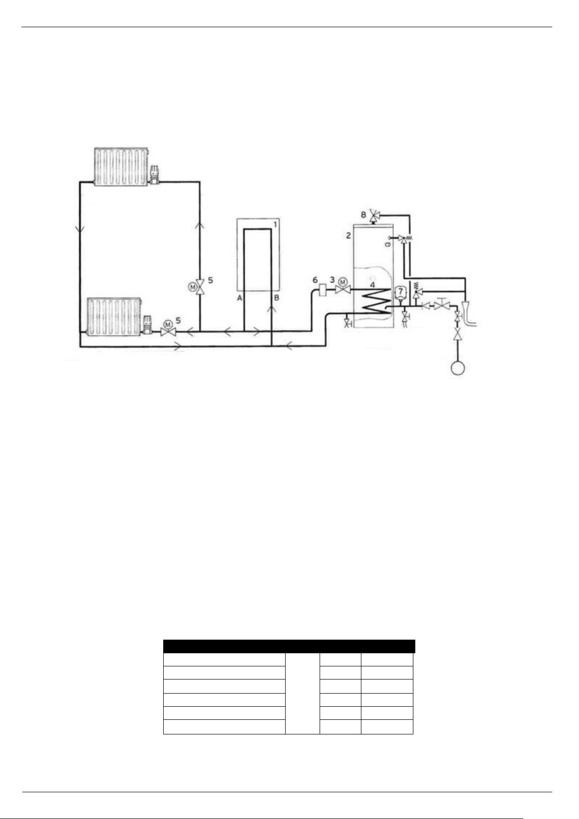
System Overview
1. Heat Source a. Heating flow
2. Cylinder b. Heating return
3. Two port motorised valve
4. Electric Immersion heater
5. Two port motorised valve
6. Auto air separator
7. Hot water expension vessel
8. Hot water thermostatic mixing valve
3 TECHNICAL DATA
3.1 Dimensions
Page 7
Unvented Hot Water Cylinder
- 7-
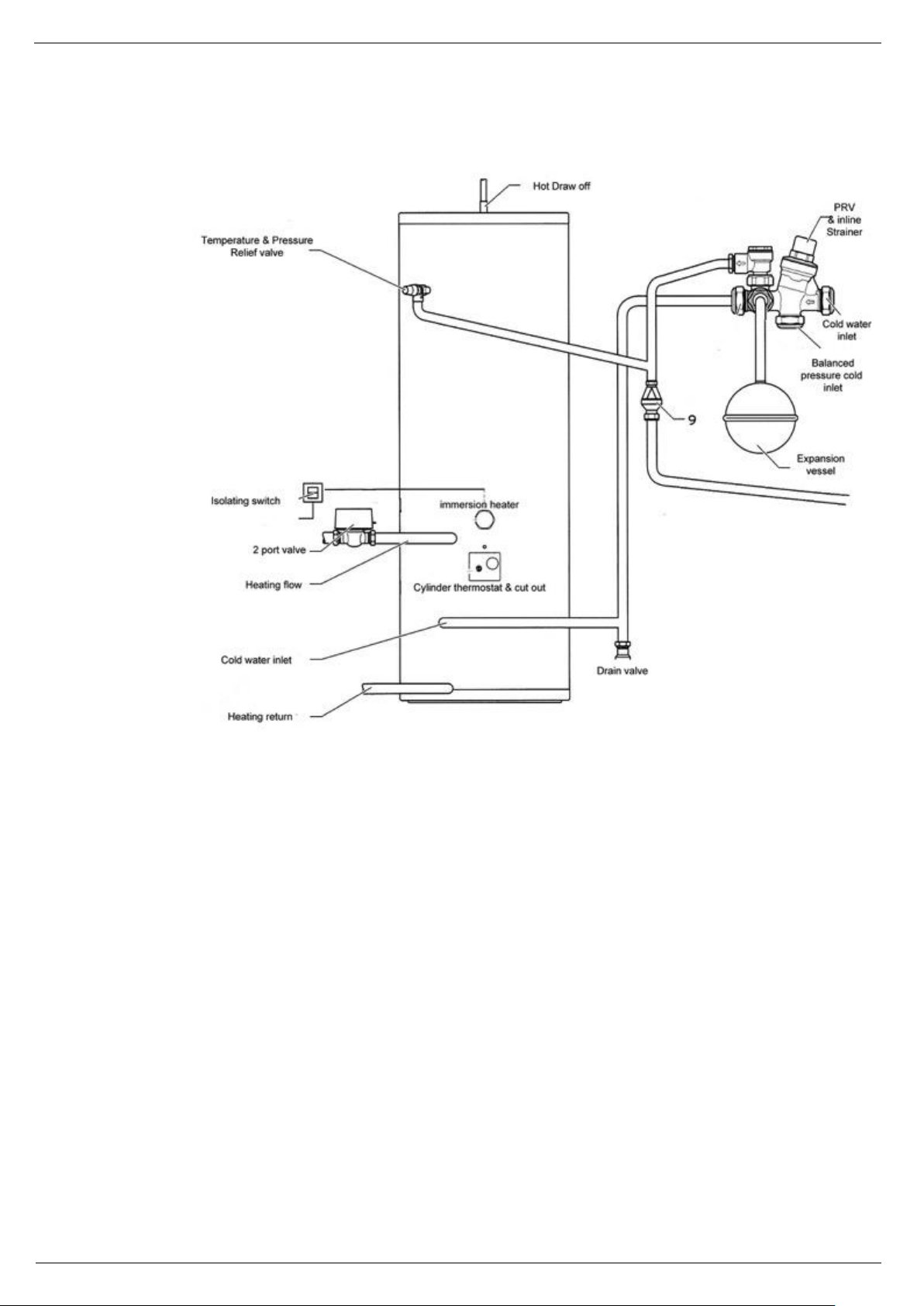
3.2 Elements of the Hot water cylinder
3.3 Safety Devices
The cylinder is delivered with all safety and control devices for the safe operation of the unvented hot water supply
system. ** denotes solar cylinder only.
Factory fitted temperature & pressure relief valve (90°C / 7 bar)
Expansion relief valve (6 bar)
Thermal cut out for immersion heater
Primary heating thermal cut out 80°C
Pressure reducing valve (3.5bar) with inline strainer
** Solar pump thermal cut-out, set at 80°C, and connected to the solar pump in order to isolate this heat
source if there is a fault in the solar controller.
** Solar cylinder thermal cut-out, set at 80°C, to be connected to the 2 port motorised valve in order to isolate
the primary heat source if the water supply thermostat fails.
Page 8
Unvented Hot Water Cylinder
- 8-
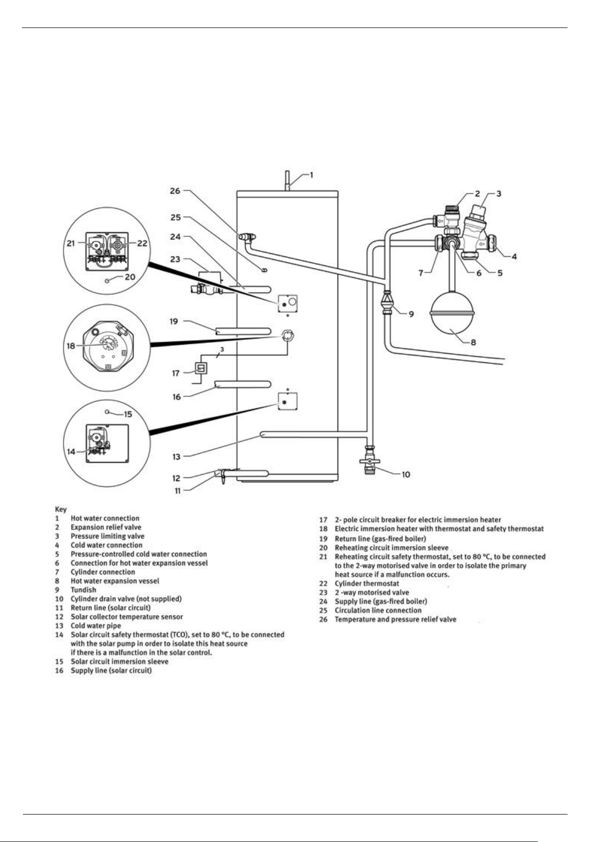
3.4 Elements of the Twin Coil (solar) Cylinder
No motorised valve is supplied for the solar pipework and it is mandatory that the solar system be supplied
with a solar hydraulic station.
The cylinder solar indirect coil can only be connected to a solar circuit that is controlled via a hydraulic
station which incorporates a pump and non-return valves.
Page 9

Unvented Hot Water Cylinder
- 9-
If a motorised valve is used this must be fitted on the primary return due to possible high temperatures of
the solar circuit.
3.5 Solar Heating system
The solar heating system is a closed hydraulic system in which the heat transfer fluid transfers the
heat to the water in the cylinder via a heat exchanger.
The water in the cylinder is heated by two separate circuits. In the lower coil the water is heated by
the solar circuit and as the water in the lower section of the cylinder is generally at a lower
temperature in enables sufficient heat transfer even when the solar radiation level is low. The
upper coil is heated by an external heat source (boiler or immersion heater) and heats the upper
section of the cylinder from which hot water is drawn for domestic purposes.
3.6 Cylinder control components
Page 10
Unvented Hot Water Cylinder
- 10-
Information inspection access to the cylinder is available by removal of the immersion heater boss.
Page 11
Unvented Hot Water Cylinder
- 11-
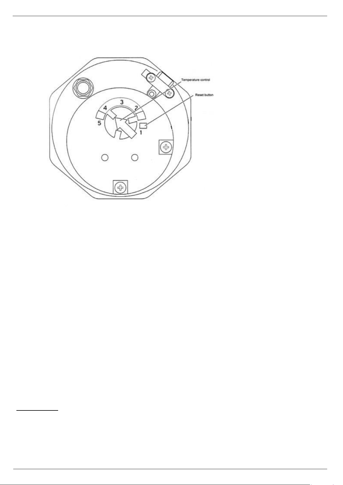
3.7 Immersion Heater
Hot water temperature Settings –
1. 20°c
2. 35°c
3. 45°c
4. 60°c
5. 68°c
The cylinder is equipped with an additional electric immersion heater with an output of 3kW. The immersion
heater will be found under the top front cladding and is designed for use in unvented cylinders. It has a
temperature controller and a thermal cut out. To set the temperature required simply turn the arrowhead so
that it points at one of the numbers between 1 and 5. The list above shows the approximate temperature for
each setting.
When required the immersion heater boss can be used as an access to view internal of the cylinder
You can also control the temperature using a separate hot water control device with a suitable dual channel
230v timer.
Information inspection access to the cylinder is available by removal of the immersion heater boss.
Page 12

Unvented Hot Water Cylinder
- 12-
3.8 Technical data table
Page 13

Unvented Hot Water Cylinder
- 13-
Indirect single coil
120L
150L
180L
210L
250L
310L
Footprint (minimum)
m
0,55 x 0,64
Hot water capacity
l
104.9
136.7
166.4
203.9
247.5
274.7
Weight Empty
Kg
26.8
28.9
32.4
36.8
40.7
45.9
Minimum ceiling height required
m
1174
1424
1774
2034
2344
2500
Maximum design pressure
bar
10
Cylinder
Tested in accordance with
EN 12897:2006
Normal operating pressure
bar
3
Cold connection (CW)
22 mm
Hot connection (DHW)
22 mm
Pressure reducing valve pressure
bar
3
Cylinder T&P
°c/bar
90/7
Expansion Valve setting
bar
6
Expansion Vessel pressure
bar
3
Max design pressure - Coil
bar
16
Max primary operating pressure
bar
3
Max working temperature - tank
°c
85
Max operating pressure - vessel
bar
6
Max design pressure - Tank
bar
7
Indirect Cylinder
Connections
22mm
Coil Surface area
m3
0.62
0.62
.75
.75
.75
.75
Coil Rating
kW
18.4
18.8
22
22.6
22.3
20.9
Coil length
8.97
8.97
10.85
10.85
10.85
10.85
Weight when full
Kg
146
178
209
248
291
345
Reheat times 15°c– 60°c
min
18
23
24
28
35
41
Primary heater pressure drop
mb
109
109
124
124
124
124
Primary flow rate
l/h
1400
1400
1400
1400
1400
1400
Heat Loss W 51
60
67
77
89
103
Heat Loss EN 12897:2006
kWh/24h
1.22
1.43
1.62
1.86
2.13
2.53
Energy Rating
B C C C C D
Max operating temperature fluid
°c
85
Electrical Supply
Electrical Supply
V
240
Amp
A
12.5
Electric protection
IP24
Electric Heater Rating
kW 3
Electric Heater Type
Single Phase
EPS Insulation (NeoPor grade)
Thickness
mm
50
50
50
50
50
50
Direct Cylinder
6 kW Reheat time 15°c– 60°c
min
69
93
112
130
155
186
Actual water volume
l
121.3
151.2
179.3
213.9
253
301.8
Weight when full
Kg
148
180
212
251
294
348
Heat Loss W 53
62
70
80
91
105
Heat Loss EN 12897:2006 -
kWh/24h
1.27
1.48
1.68
1.92
2.19
2.53
Energy Rating
C C C C C D
Page 14

Unvented Hot Water Cylinder
- 14-
Twin Coil Solar Cylinder
210L
250L
300L
Hot water capacity
Upper Coil L 106
142
144.7
Lower Coil L 202.1
246.1
271.3
Coil Surface
Upper Coil L 0.5
0.5
0.5
Lower Coil L 0.62
0.62
0.62
Coil Length
Upper Coil m 7.25
7.25
7.25
Lower Coil m 9 9 9
Coil Rating
Upper Coil
kW
15.7
15.6
15.5
Lower Coil
kW
18.6
18.4
17.1
Reheat Time
Upper Coil
min
21
27
29
Lower Coil
min
34
40
49
Primary heater pressure
drop
Upper Coil
mb
90
91
92
Lower Coil
mb
118
117
117
Primary Flow rate
Upper Coil
l/h
1400
1400
1400
Lower Coil
l/h
1400
1400
1400
Heat Loss W
79
91
105
Weight Empty
Kg
40
43
50
Weight Full
Kg
246
288
343
Actual water volume
L
205.6
244.5
292.8
Dedicated solar Vol
L
99.6
102.5
148.1
Heat Loss
W
79
91
105
Energy Rating
C C
D
Page 15

Unvented Hot Water Cylinder
- 15-
Qty 1 Vokèra unvented water heater incorporating immersion heater & thermal controls
Qty 1 Factory fitted dual stat
Qty 1 Guarantee card
Qty 1 Installation and service manual
Qty 1 Accessories Kit
Code
Description
Quantity
29450020 / 29450021
Vokèra Kit A 120/150 S/C
12l pot vessel 3.0bar c/w brkt vertical
1
1/2" mt.draincock type a
1
3/4"bsp hose c/w sealing washer-1000mm
1
tee piece 22mm comp. x 3/4" m x 3/4" f
1
15*22mm tundish slimline straight black
1
compact inlet control 3/6 bar
1
rwc 2 port 22mm zone valve
1
29450022 / 29450023
Vokèra Kit B 180 /210 S/C & D/C
18l pot vessel 3.0bar c/w brkt vertical
1
1/2" mt.draincock type a
1
3/4"bsp hose c/w sealing washer-1000mm
1
tee piece 22mm comp. x 3/4" m x 3/4" f
1
15*22mm tundish slimline straight black
1
compact inlet control 3/6 bar
1
rwc 2 port 22mm zone valve
1
29450024 / 29450025
Vokèra Kit C Inox 250/310 S/C & D/C
24l pot vessel 3.0bar c/w brkt vertical
1
1/2" mt.draincock type a
1
3/4"bsp hose c/w sealing washer-1000mm
1
tee piece 22mm comp. x 3/4" m x 3/4" f
1
15*22mm tundish slimline straight black
1
compact inlet control 3/6 bar
1
rwc 2 port 22mm zone valve
1
3.9 Pack contents
3.10 Kit contents
Page 16

Unvented Hot Water Cylinder
- 16-
Vokèra Kit D Inox 180 / 210L Direct
18l pot vessel 3.0bar c/w brkt vertical
1
1/2" mt.draincock type a
1
3/4"bsp hose c/w sealing washer-1000mm
1
15*22mm tundish slimline straight black
1
compact inlet control 3/6 bar
1
Vokèra Kit E Inox 250/310L Direct
24l pot vessel 3.0bar c/w brkt vertical
1
1/2" mt.draincock type a
1
3/4"bsp hose c/w sealing washer-1000mm
1
15*22mm tundish slimline straight black
1
compact inlet control 3/6 bar
1
Vokèra Kit F Inox 210L S/C HP
18l pot vessel 3.0bar c/w brkt vertical
1
1/2" mt.draincock type a
1
3/4"bsp hose c/w sealing washer-1000mm
1
15*22mm tundish slimline straight black
1
compact inlet control 3/6 bar
1
rwc 2 port 22mm zone valve
1
Vokèra Kit G Inox 250/300L S0D/C HP
24l pot vessel 3.0bar c/w brkt vertical
1
1/2" mt.draincock type a
1
3/4"bsp hose c/w sealing washer-1000mm
1
15*22mm tundish slimline straight black
1
compact inlet control 3/6 bar
1
rwc 2 port 22mm zone valve
1
Vokèra Kit H Inox 210L HP
12l pot vessel 3.0bar c/w brkt vertical
1
1/2" mt.draincock type a
1
3/4"bsp hose c/w sealing washer-1000mm
1
15*22mm tundish slimline straight black
1
compact inlet control 3/6 bar
1
Page 17

Unvented Hot Water Cylinder
- 17-
4 INSTALLATION AND COMMISSIONING
(To be installed by qualified personnel only)
Installation site
Position the domestic hot water cylinder as near as possible to the heat source to prevent heat loss
Please adhere to the following instructions
The tundish discharge pipe must be installed with a minimum downward slope of 1:200 and must terminate in
a safe and visible place
The installation surface must be level and have the strength to bear the weight of the full cylinder
The installation must not be at risk of frost
The control system for the cylinder must be accessible to the service engineer
There must be sufficient space for installing, maintaining and replacing the expansion vessel.
There must be sufficient space for installing, maintaining and replacing the immersion heater
Choose a site that has simple access for the necessary supplies
To prevent heat loss ensure exposed pipework is insulated
4.1 Installing pipes for the heating circuit
Ensure that the pipes in the circuit have a minimum diameter of 22mm and are as short as possible from the heat
source to prevent heat loss.
The two port motorised valve prevents the cylinder from overheating and should be installed in the flow line of the heat
source, (the direction of flow is marked with arrows).
Connect the hot water pipe to the 22mm hot water draw off of the cylinder, continue the pipe until the first T junction.
Page 18

Unvented Hot Water Cylinder
- 18-
A secondary circulation line increases energy consumption, please only install if required for demand and
temperature reasons. If it is unavoidable keep operations to a minimum and connect a WRAS approved
pump together with a non-return valve and connect to the hot water pipe. (Please note that a second
expansion vessel may be required in this instance). A 15mm connection is fitted for the secondary circulation
line in the cylinder which is supplied with a cap if not being used. When a secondary return circuits are used then
an additional expansion vessel may be required
4.2 Cold mains inlet
The efficiency of an unvented cylinder depends on the available pressure of the cold mains inlet and flow
rate. The measured static pressure must be at least 2.0 bar. A corresponding flow rate of 20 – 25 l/min must
be available. If the pressure is below 1 bar please seek advice on an alternative hot water supply system.
4.3 Safety Assembly
Warning: Excess pressure can cause the cylinder to burst – ensure that there is no stop valve between the
safety assembly and the cylinder.
This one piece inlet control incorporates several different controls devices in one, it is specifically designed for
use on an unvented system to control the incoming water supply to a hot water cylinder or similar application.
Compact and lightweight in design the valve incorporates several different controls: A ‘drop tight’ pressure reducing
valve meaning the valve will hold at the pre-set pressure regardless of it being under flow or no flow conditions or
regardless of fluctuating inlet pressures, a single check valve which will protect the system for backflow prevention up
to fluid category 2, and a pre-set pressure relief valve which will prevent the system from over pressurisation. The
expansion relief valve is designed so it can rotate, to allow the discharge connection to be easily fitted in various
directions making installation simple. The valve also includes a specific connection for a balanced cold water take off
which can allow the user to connect a cold water feed direct from the inlet control valve, and a dedicated connection
for an expansion vessel.
During installation position the valves so that you can connect the 15mm connection of the expansion relief valve with
the tundish. The flow direction is marked with arrows.
Page 19

Unvented Hot Water Cylinder
- 19-
Warning : Ensure that the expansion relief valve is not covered or closed
Install the discharge pipe of the expansion relief valve with a constant fall to the outside. The discharge pipe must finish
at a safe and visible height where there is no danger of it freezing and where there is no danger of injury to persons.
Actuate the expansion relief valve regularly to prevent scaling.
Connect the cylinder via the cylinder connection
Use 22mm copper pipe to connect the cylinder from the main stop valve to ensure that the cylinder is as efficient as
possible. This is particularly important for installations with a balance cold water inlet
Install the safety assembly in the cold mains inlet on the cylinder
If necessary establish the connection to the cold water inlet with pressure compensation of the safety assembly
Dependent on the fittings used and the type of draw off points it may be necessary to install a backflow preventative
device in the cold water inlet.
WARNING: Water temperature over 50°C running from taps may immediately cause serious burns. Children,
disabled and elderly run a greater risk in this regards. Therefore it is advisable to use a thermostat mixing valve
connected to the water outlet or where preferred at the point of use.
Expansion vessel
To prevent any overpressures that might damage the equipment, frequently triggering the safety unit and causing water
dripping, it is mandatory that you install the expansion vessel included in the kit. Install it in accordance with the
instructions provided by the manufacturer. The expansion cylinder is required to keep pressure constant and avoid harmful
pressure shocks or accidental overpressures.
CAUTION! It is essential you install the expansion vessel vertically with connection at the bottom (see the figure
below)
CAUTION: Where secondary return circuits are used (SR) an additional expansion vessel may be required
Page 20

Unvented Hot Water Cylinder
- 20-
4.3.1 Building Regulation G3
The following text is reproduced from the Building Regulations.
It is included here for reference only.
Discharge pipes from safety devices
Discharge pipe D1
3.49 Each of the temperature relief valves or combined temperature and valves specified should discharge either directly
or by way of a manifold via a short length of metal pipe (D1) to a tundish.
3.50 The diameter of discharge pipe (D1) should be not less than the nominal outlet size of the temperature relief valve.
3.51 Where a manifold is used it should be sized to accept and discharge the total discharge from the discharge pipes
connected to it.
3.52 Where valves other than the temperature and pressure relief valve from a single unvented discharge by way of the
same manifold that is used by the safety devices, the manifold should be factory fitted as part of the hot water storage
system unit or package.
Tundish
3.53 The tundish should be vertical, located in the same space as the unvented hot water storage system and be fitted as
close as possible to, and lower than, the valve, with no more than 750mm of pipe between the valve outlet and the tundish
(see Diagram1).
Note: To comply with the Water Supply (Water Fittings) Regulations, the tundish should incorporate a suitable air gap.
3.54 Any discharge should be visible at the tundish. In addition, where discharges from safety devices may not be apparent,
e.g. in dwelling occupied by people with impaired vision or mobility, consideration should be given to the installation of a
suitable safety device to warm when discharge takes place, e.g. electronically operated.
Discharge pipe D2
3.55 The discharge pipe (D2) from the tundish should:
a. Have a vertical section of pipe at least 300mm long below the tundish before any elbows or bends in pipework (see
Diagram 1); and
b. Be installed with a continuous fall thereafter of least 1 in 200.
3.56 The discharge pipe (D2) should be made of:
a. Metal; or
b. Other material that has been demonstrated to be capable of safely withstanding temperatures of the water
discharged and is clearly and permanently marked to identify the product and performance standard (e.g. as
specified in the relevant part of BS 7291).
3.57 The discharge pipe D2 should be at least one pipe size larger than the nominal outlet size of the safety device unless its
total equivalent hydraulic resistance exceeds that of a straight pipe 9m long, i.e. for discharge pipes between 9m and 18m
the equivalent resistance length beat least two sizes larger than the nominal outlet size of the safety device; between 18m
and 27m at least 3 sizes larger, and so on; bends must be taken into account in calculating the flow resistance. See diagram
1, table 1 and worked example.
Note: an alternative approach for sizing discharge pipes would be to allow Annex D, section D.2 of BS 6700:2006
Specification for design, installation, testing and maintenance of devices supplying water for domestic use within buildings
and their curtilages.
Page 21

Unvented Hot Water Cylinder
- 21-
Valve outlet
size
Minimum size of discharge to
Tundish (D1)*
Minimum size of discharge pipe
from Tundish (D2)*
Maximum resistance allowed
expressed as a length of straight
pipe, i.e. elbows or bends
Resistance created by each
elbow or bend
G ½
15mm
22 mm
38 mm
35 mm
up to 9 m
up to 18 m
up to27 m
0.8 m
1.0 m
1.4 m
G ¾
22 mm
28 mm
35 mm
42 mm
up to 9 m
up to 18 m
up to27 m
1.0 m
1.4 m
1.7 m
G 1
28 mm
35 mm
42 mm
54 mm
up to 9 m
up to 18 m
up to27 m
1.4 m
1.7 m
2.3 m
Diagram 1 – Typical discharge pipe arrangement
Table 1 – Sizing of copper discharge pipe ‘D2’ for common temperature relief valve outlet sizes
*See 3.49 and 3.56 and Diagram 1
Note: The above table is based on copper tube. Plastic pipes may be of different bore and resistance.
Sizes and maximum lengths of plastic should be calculated using data prepared for the type of pipe being used.
Worked Example
The example below is for a G ½ 6 with discharge pipe (D2) having 4 No. 22mm elbows and length of 7m from the tundish to
the point of discharge.
From Table1
Maximum resistance allowed for a straight length of 22mm copper discharge pipe (D2) from a G ½ temperature relief
valves is: 9.0m
Subtract the resistance for 4 No.22mm elbows at 0.8m each=3.2m
Therefore the maximum permitted length equates to: 5.8m which is less than the length of 7m therefore calculated the next
largest size.
Maximum resistance allowed for a straight length of 28mm copper discharge pipe (D2) from a G ½ temperature relief
valve is. 18m
Subtract the resistance for 4 No.28mm elbows at 1.0m each=4m
Therefore the maximum permitted length equates to: 14m
As the actual length is 7m, a 28mm (D2) copper pipe will be satisfactory.
3.58 Where a single common discharged pipe serves more than one system, it should be at least one pipe size larger than
the largest individual discharge pipe (D2) to be connected.
3.59 The discharge pipe should not be connected to a soil discharge stack unless it can be demonstrated that the soil
discharge stack is capable of safely withstanding temperatures of the water discharged, in which case, it should:
Page 22

Unvented Hot Water Cylinder
- 22-
a. Contain a mechanical seal, not incorporating a water trap, which allows water into the branch pipe without allowing
foul air from the drain to be ventilated through the tundish;
b. Be a separate branch pipe with no sanitary appliances connected to it;
c. If plastic pipes are used as branch pipes carrying discharge from a safety device they should be either polybutylene
(PB) to Class S of BS 7291-2:2006 or cross linked polyethylene (PE-X) to Class S of BS 7291-3:2006;and
d. Be continuously marked with a warning that no sanitary appliance should be connected to the pipe.
4.4 Unit filling
WARNING: Switching on the equipment when it is not filled with water will seriously damage the electric heating
element.
WARNING: In the presence of water with a hardness degree >200ppm it is mandatory that you install a softener to
reduce limestone scaling inside the cylinder and keep the electric heating element and the hydraulic safety unit in
good working order.
To fill the equipment you need to:
• The tap present in the hydraulic unit must be put in the open position, the opening of the tap allows the equipment’s
supply. The retain system incorporated in the safety hydraulic unit prevents from the heat water return.
• open the main water supply or the equipment water supply cock;
• open a hot water tap (e.g. bathroom, wash basin, etc.) to allow the water to flow out; when the water outflow from the
tap is constant the equipment will be full;
• check that there are no leaks from the various hydraulic connections;
We recommend that you clean the pipes before laying them.
Only proceed with the electrical connection after performing this operation
4.5 Electrical connection
Wiring should be installed by a qualified, competent person in accordance with the prevailing building regulations, part P of
the current IEE regulations and all other directives.
WARNING: Switching on the equipment when it is not filled with water will seriously damage the electric
heating element.
WARNING: If the supply cable is damaged, it must be replaced by the manufacturer or by its technical support
service or a suitably qualified person.
Standard commercial cables can be used, 230 V supply lines must be laid separately above lengths of 10m.
The discharge pipes of the tundish, drain valves and motorised valves must be laid at distance from all electrical
components.
Before wiring the control components dismantle the casing to facilitate the work. Utilise the cut outs in the casing for
routing cables.
DANGER – Without earthing life threatening voltage can reach the pipework and
draw off points – it it imperative that you earth the immersion heater
Ensure that both hot and cold pipes are connected to the earth line by means of an
earth cable directly on the cylinder.
Page 23

Unvented Hot Water Cylinder
- 23-
You must also ensure that the immersion heater is connected to the earth line via
the earth terminal.
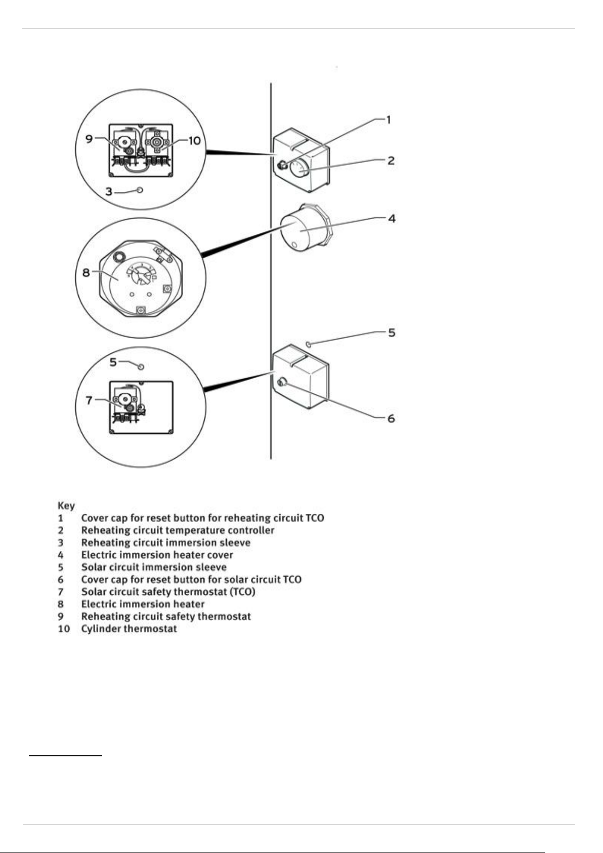
Cylinder thermostat and thermal cut-out for reheating circuit
Electrical connection of the immersion heater
Page 24

Unvented Hot Water Cylinder
- 24-
Only switch the immersion heater on when the cylinder is full
4.6 Safety limiting device (manual reset
Reset, after eliminating the causes of intervention, as follows:
- disconnect the power supply;
- remove the protection cover fixing screws;
- lightly press the thermostat reset button, using an insulated object with round tip, in the position indicated, until
hearing a click.
Page 25

Unvented Hot Water Cylinder
- 25-
Technical data
Max Pressure: 7 bar
Max Temperature: 90°C
Technical data
240V, 0.04°, 6/5W, 50/60Hz
Max Diff. Press. : 55.2kPa (8psi)
Max. Stat. Press. : 863 kPa (125 psi)
Max. Fluid Temp. : 5-88 °C (40-190°F)
Max. Ambient Temp. : 52°C (125°F)
Hot water Only
Technical data
Temperature range: 25±5 ÷ 65±3°C
Temperature differential: Δt 8±2 K
Limit temperature: FIX 80±3°C
Fail safe: YES
Differential (Manual Reset): 20±5°C
Max. body temperature: T 80°C
Max. bulb temperature: T 125°C
Ambient temperature effect: -0.12°C/°C *
Fairlead: M20x1.5
Degree of protection: IP40
Contact rating: N-A 10(2,5)A/250V~
Change in switching pint refer to maximum change of the value of ambient
temperature
4.7 Solar controller - When the solar controller is used as the normal control thermostat on
the cylinder and the cylinder incorporates a high limit thermostat for the solar circuit
4.8 T&P
4.9 Motorized Zone Valve
4.10 Dual Thermostat
4.11 Drainage
Typical drain arrangement and system design.
Page 26

Unvented Hot Water Cylinder
- 26-
4.12 Unit emptying
Should the unit be going to remain unused for a prolonged time, we recommend that you empty it. In this case proceed as
follows:
• cut off the power supply and the main water supply;
• open a hot water tap to allow air to flow in;
• turn the emptying knob on the hydraulic safety unit to the open position;
• verify that the discharge connector of the hydraulic safety unit is connected to a drain as specified in par. 3.1.1.
4.13 Restart after a long term stop
When the unit is restarted after a long term stop (trail running included), it is normal that outlet water is unclean. Keep the
tap on and the water will be clean soon.
5 COMMISSIONING SYSTEM
IMPORTANT: It is the responsibility of the installer to ensure that the system is properly commissioned and the end
user instructed in the safe operation of the equipment.
The thermostat on the immersion heater should be adjusted to trip at 60°C. This is the ideal temperature to prolong
element life in hard water areas. Scale on the sheath builds up more rapidly at temperatures above this causing the
element to overheat and premature failure can occur. Higher temperatures without additional controls would result in
scalding. In known hard water areas the use of a scale inhibitor is also recommended.
In addition to the thermostat the thermal cut-out will switch power off to the element should the thermostat
malfunction, causing an excessive rise in water temperature. The thermal cut-out can be reset manually after the fault
has been corrected
5.1 Electrical Check
Check that all wiring including earth wiring, has been installed correctly, conform to current regulation and
satisfactory electrical test and inspection certificate has been completed.
Check all electrical covers are correctly fitted;
Check Tundish is positioned so that any spillage or spray from the Tundish would not contact any electrical
components.
Check all wiring connections have been made.
Check the required earth continuity conductors have been fitted.
Page 27

Unvented Hot Water Cylinder
- 27-
5.2 Pre-Fill Check
Check the expansion vessel is fitted and that no valves are fitted between the expansion vessel and the
combination valve.
Check that no valves are fitted between indirect water heater and the combination valve.
Check the PRV, tundish and discharge pipes are corrected installed to conform to the Building Regulation G3.
Check all pipes connections are tight and no joints have been left unsoldered.
Check all drain cocks are closed.
5.3 Fitting System
Close all isolating valves.
Close all taps.
Open the incoming water mains stopcock.
Turn on mains water, allow system to fill up to first isolating valve. Turn on hot taps. Open isolating valves and allow
the indirect water heater to fill and let water pass through the system to the open hot tap, this will expel most of air
from the system and fill the indirect water heater vessel.
Systematically open all hot and cold taps to purge air.
Check system for leaks.
Check no water is discharging from T&P or PRV.
Expansion vessel – with the water supply turned off and taps open, check expansion vessel pressure and top up as
necessary.
Cylinder T&P – check its operation; with the water supply on, turn the T&P test knob and check water discharges to
tundish, ensure the valve closes after testing.
Discharge pipe (D1) – open either T&P or PRV gradually to produce all full bore discharge into tundish and D2 and
check there is no back pressure, and that the water flows freely to drain.
Pressure Reducing Valve (PRV) – check that the correct outlet pressure is being maintained by measuring the
pressure at an in-line terminal fitting e.g. a tap.
When necessary the immersion heater boss can be used as an access to view internal of the cylinder
5.4 Drain System
Turn off incoming mains stop cock.
Using hose and suitable containers, drain all water from the cylinder and pipework using drain cocks.
Remove and clean in-line strainer of combination valve.
5.5 Cleaning The System
Using proprietary chlorination product, chlorinate domestic hot water system as per manufacturer’s instruction.
Drain the system as 4.15, then fill and drain to flush as many times as recommended by chlorination product
manufacturer.
Refill system.
5.6 Setting And Testing Controls
Switch on indirect water heater electric isolating switch.
For commissioning use the factory default setting, no changes parameters should be required.
Set indirect water heater into operation, and when hot check for leaks.
Check operating of any open flue appliances that could be affected by air movement through the indirect water
heater.
Fill in details in the Benchmark Logbook.
Page 28

Unvented Hot Water Cylinder
- 28-
5.7 Handing Over
Complete the Benchmark Logbook.
The installer should re-check the system and ensure it’s completely satisfactory before demonstrating to the end
user.
The end user should be aware of the following:
The most cost effective use of the indirect hot water system using the automatic mode.
How to set the temperature of the tap hot water.
How to set the different functions.
The function of the combination valve’s PRV and that over pressure will cause steam and scalding water to be
emitted from the discharge pipes.
That the tundish is supplied as a visual identification for over pressure.
The procedure to follow in event of over pressure.
IMPORTANT: This manual must be left with the end user together with the Service record / Logbook.
6 MAINTENANCE INSTRUCTIONS
(Qualified personnel only)
WARNING: the repair and/or maintenance operations must only be performed by qualified personnel. Only use
genuine spare parts. Prior to undertaking any maintenance operations, turn off and disconnect the equipment from
the mains electrical supply before commencing any work on the Cylinder. We recommend that you purchase any
spare parts from only authorised dealers or directly from the Manufacturer.
6.1 General
• Control regularly the connection between the supply plug and wiring.
• If the system is not used for a long period, empty the cylinder in order to avoid freezing.
• It is advised to clean regularly the inside part of the cylinder and the electric heating element in order to preserve the
efficiency.
• Control the magnesium anode and change it if needed.
• Clean the air filters each month in order to preserve the heating performance.
• Before turning off the system for a long period you must:
- Remove the current supply;
- Drain all the water from the cylinder and the pipes;
- Close all valves ;
- Control regularly all inside components.
6.2 Water circuit / Condensate discharge
The water circuit check is limited to the integrated filter installed by the customer (if any; in this case follow the instructions
provided by the valve manufacturer); also check the tightness of the valves, of the screw connections, etc.; should they be
loose, have them tightened by technicians.
Page 29

Unvented Hot Water Cylinder
- 29-
6.1 Replacement of the electric immersion heater
If replacement of the electric immersion heater is required follow this procedure.
Procedure:
• Turn off the unit;
• Disconnect product from the electrical supply
• Empty the cylinder until the water level seems to be lower than the place where the electric immersion heater is joined;
• Remove the immersion heater cover. Disconnect the cable from the thermostat
• Remove the thermostat
• Disconnect and replace the electric immersion heater; Replace the O-Ring if necessary.
• Replace the thermostat
• Restore the electric connections;
• Replace the immersion heater cover
• Fill the cylinder and check for leaks;
• Restore the connection to the electric supply;
6.2 Outer cover cleaning
For the cleaning of the outer shell only use a damp cloth. Do not in any circumstances use abrasive products containing
organic thinners (alcohol, benzene, etc.).
6.3 Hydraulic safety unit efficiency check
The hydraulic unit efficiency is very important to prevent any overpressures inside the cylinder (that would damage it), and
allows the user to safely operate the equipment. Periodically check the efficiency of the hydraulic safety unit, according to
the instructions provided by the manufacturer. Follow the instructions provided by the manufacturer. During the check
clean the unit and remove any limescale.
6.4 General notes
Always use tools that are appropriate for the intended purpose.
Always replace the gaskets and/or the o-rings ensuring the hydraulic sealing.
Only use genuine spare parts.
During reinstalling make sure that:
• the resistance is properly housed and the sealing gaskets are correctly installed;
• the safety and regulation devices (thermostats) are properly installed inside their housings;
• before reconnecting the equipment to the mains fill it (referring to the appropriate section) and check that there are no
water leaks.
6.5 After-sales service
In case of errors or malfunctions, switch off the equipment and disconnect the power supply. Then contact the technical
support service.
Page 30

Unvented Hot Water Cylinder
- 30-
Fault
Cause
Remedy
The cylinder cools down at night
One pipe circulation in the case of
short tube networks with low
pressure loss
Install a non-return valve as close as
possible to the cylinder
Primary heating not working. Boiler
runs for short periods repeated until
cylinder reaches temperature
air in the reheating chamber
Vent the reheating heat exchanger.
Heat exchanger surface area too
small
Compare the data provided by the
boiler manufacturer with the cylinder
data it may be possible to cure by
setting a higher flow rate on the
boiler
Only cold or lukewarm water at draw
off
The cold and cold draw offs have
been reversed
Turn off the cold water supply and let
the water flow out via the how draw
off. Only a few litres of water will
flow if the setup is correctly. The hot
water withdrawal pipe intake is then
in air space and further draining is not
possible. If it is possible to drain the
entire cylinder via the hot draw off
then the connections are incorrect.
Change the connections.
Hot water thermostat set too low
Increase the setting
Heating insufficient – boiler doesn’t
reheat
External control device faulty
Air in the reheating heat exchanger
Check boiler is working
Check controls are working and that
the 2 port valve is in the DHW
position
Vent the reheating heat exchanger
Page 31

Unvented Hot Water Cylinder
- 31-
Cylinder sensor faulty
Check thermal cut out and replace if
faulty
Water flows from the expansion relief
valve when heating up
Dirt on the valve seat
Check and repair
PRV Faulty
Check an replace if faulty
Expansion vessel faulty
Check pressure, if insufficient repressurise and replace if pressure not
held
Expansion relief valve faulty
Check if pressure is normal and
replace if faulty
Water flows from the temperature
and pressure relief valve when
heating up
Dirt in the valve seat
Check and repair
Boiler temperature control system
faulty
Check boiler control system and that
the 2 port valve switches when
cylinder temperature reached
Cylinder sensor faulty
Check sensor and TCO replace if
faulty
T & P relief valve faulty
If water escapes when only heated by
the immersion replace the T & P relief
valve
Immersion heater faulty
Check thermal cut out and replace if
faulty
Page 32

Unvented Hot Water Cylinder
- 32-
6.6 Service record / Logbook
Page 33

Unvented Hot Water Cylinder
- 33-
Page 34

Unvented Hot Water Cylinder
- 34-
DISPOSAL OF WASTE ELECTRICAL AND ELECTRONIC EQUIPMENT (2002/96/EC – WEEE DIRECTIVE)
This symbol indicates that the appliance must not be treated as domestic waste upon disposal.
Rather, it must be delivered to an authorized collection centre for the recycling of electrical and electronic
appliances.
Proper disposal of this appliance will avoid potential health hazards and adverse consequences for the environment.
Recycling of materials helps to preserve natural resources.
For further information about the recycling of this appliance, please contact your municipal offices, your domestic waste
disposal service or the retailer/installer from whom the appliance was purchased.
The penalties for failure to comply with these disposal procedures are laid down in local legislation.
 Loading...