

Page 1
Supplied By www.heating spares.co Tel. 0161 620 6677
ESC
Installation
& Servicing
Instructions
THESE INSTRUCTIONS
TO BE RETAINED
BY USER
Page 2
Supplied By www.heating spares.co Tel. 0161 620 6677
Contents
Design principles & operating sequence Page
1.1 Principle components 2
1.2 Mode of operation (at rest) 2
1.3 Domestic hot water mode 2
1.4 Central heating mode 2
1.5 Safety devices 2
Technical data Page
2.1 Central heating 3
2.2 Domestic hot water 3
2.3 Gas pressure 3
2.4 Expansion vessel 3
2.5 Dimensions 3
2.6 Clearances 3
2.7 Connections 3
2.8 Electrical 3
2.9 Flue details 3
2.10 Efficiency 3
2.11 Parameter defaults 4
2.12 Emissions 4
2.13 Pump duty 4
General requirements Page
3.1 Related documents 5
3.2 Location of appliance 5
3.3 Gas supply 5
3.4 Flue system 5
3.5 Air supply 6
3.6 Water circulation 6
3.7 Electrical supply 7
3.8 Showers 7
3.9 Mounting on a combustible surface 7
3.10 Timber framed buildings 7
3.11 Condensate disposal 7
3.12 Inhibitors 7
Installation Page
4.1 Delivery 7
4.2 Contents 7
4.3 Unpacking 7
4.4 Preparation for mounting the appliance 7
4.5 Fitting the flue 8
4.6 Connecting the gas & water 11
4.7 Condensate outlet 12
4.8 Electrical connections 12
Commissioning Page
5.1 Gas supply installation 14
5.2 The heating system 14
5.3 Initial filling of the system 14
5.4 Initial flushing of the system 14
5.5 Filling the hot water system 14
5.6 Pre-operation checks 14
5.7 Initial lighting 14
5.8 Final flushing of the heating system 14
5.9 Operating parameters 14
5.10 Functional parameters 15
5.11 Range rating 15
5.12 Setting the system design pressure 15
5.13 Regulating the central heating system 16
5.14 Final checks 16
5.15 Instructing the user 16
Servicing Page
6.1 General 17
6.2 Routine annual servicing 17
6.3 Replacement of components 17
6.4 Component removal procedure 17
6.5 Pump head removal 17
6.6 Safety valve removal 17
6.7 Automatic air valve removal 17
6.8 Pressure gauge removal 18
6.9 Temperature sensor removal 18
6.10 Main PCB removal 18
6.11 Gas valve removal 18
6.12 Fan removal 19
6.13 Burner removal 19
6.14 Electrode removal 19
6.15 Injector removal 19
6.16 DHW heat exchanger removal 20
6.17 Motorised valve actuator removal 20
6.18 Divertor valve assembly removal 20
6.19 Condense trap removal 20
6.20 Condense pressure switch removal 20
6.21 Combustion cover removal 20
6.22 Expansion vessel removal 21
6.23 Input & status PCB removal 21
Checks, adjustments, and fault finding Page
7.1 Checking appliance operation 22
7.2 Mode of operation 22
7.3 Checking/adjusting fan speeds 22
7.4 Adjusting the gas valve 23
7.5 Status code 24
7.6 Lockout faults codes 25
7.7 Diagnostic recall 25
7.8 Temperature sensor viewing mode 26
7.9 Checking the expansion vessel 26
7.10 External faults (installation) 26
7.11 Electrical checks 26
7.12 Fault finding 27
Wiring diagrams Page
8.1 Important note 31
8.2 Installation of Vokera time clock 31
8.3 External controls 31
Exploded diagrams Page
9.1 Table 1 35
9.2 Table 2 36
9.3 Table 3 37
9.4 Table 4 38
9.5 Table 5 39
9.6 Table 6 40
L.P.G. instructions Page
10.1 Technical data 41
10.2 Related documents 41
10.3 Gas supply 41
10.4 Gas supply installation 41
10.5 Adjusting the gas valve 41
10.6 Range rating 41
Page 3
Supplied By www.heating spares.co Tel. 0161 620 6677
INTRODUCTION
The Vokera Eclipse ESC is a combined central heating
and domestic hot water condensing boiler, which – by
design – incorporates full sequence electronic ignition,
circulating pump, expansion vessel, safety valve, pressure
gauge, and automatic by-pass.
The Eclipse is produced as a room sealed, category C1,
C3, C6 appliance, suitable for wall mounting applications
only. The Eclipse is provided with a fan powered flue
outlet with an annular co-axial combustion air intake that
can be rotated – horizontally – through 360 degrees for
various horizontal or vertical applications. The Eclipse
can also be used with the Vokera twin flue system.
These appliances are designed for use with sealed
systems only; consequently they are not intended for use
on open vented systems.
A range rating facility is incorporated in the appliance.
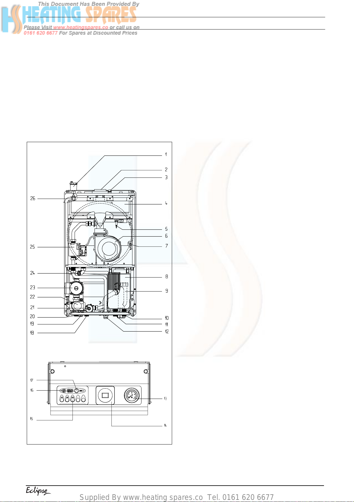
General layout
1 Auto air vent
2 Flue outlet & air intake
3 Flue gas analysis test point
4 Burner plate
5 Spark/Sensing Electrode
6 Fan assembly
7 Pressure switch
8 Electronic Control Board (PCB)
9 Condense trap
10 Cold water inlet
11 Hot water outlet
12 Gas connection
13 Pressure gauge
14 Time clock aperture
15 Function key pad
16 LED display
17 Reset button
18 Heating flow connection
19 Safety valve
20 Heating return connection
21 Auto by-pass
22 Three port valve actuator
23 Pump
24 Return sensor (NTC2)
25 Gas valve
26 Flow sensor (NTC1)
Fig. 1
1
Page 4
Supplied By www.heating spares.co Tel. 0161 620 6677
SECTION 1 DESIGN PRINCIPLES AND OPERATING SEQUENCE
1.1 PRINCIPLE COMPONENTS
● A fully integrated electronic control board
featuring electronic temperature control,
continuous air/gas modulation, anti-cycle
control, pump over-run, self-diagnostic fault
indicator, electronic ignition with flame
supervision, & appliance frost protection.
● Cast aluminium mono-block heat exchanger.
● Low Nox burner with pre-mix.
● Two-stage gas valve.
● Pump.
● Expansion vessel.
● Pressure gauge.
● Safety valve.
1.2 MODE OF OPERATION (at rest)
When there is no demand for heating or hot
water, the boiler will periodically light to pre-heat
the domestic hot water heat exchanger to
approximately 55°C. This ensures that the
appliance is at operating temperature when there
is a request for domestic hot water. The parameter
for the allowable temperature drop – between preheat operation – can be adjusted. If the appliance
remains inactive for a period of 24 hours, the pump
and motorised valve will be energised for a few
moments to prevent these components from
seizing. Should the flow temperature sensor fall
below 7°C the pump will be energised.
If the flow sensor temperature falls to below 3°C
the burner will be lit and the appliance will operate
at the minimum output until the temperature of
the flow sensor reaches 10°C, whereupon the
pump will continue to run in pump over-run mode.
1.3 DOMESTIC HOT WATER MODE
When the appliance is at rest, the motorised
valve is energised to the hot water position, when
a demand for hot water is made the cold water
temperature sensor activates the pump and fan.
When the fan is sensed to be operating correctly,
the ignition sequence commences. The speed of
the fan and therefore the output of the boiler is
determined by the temperature of the water
sensed by the return temperature sensor,
consequently a high temperature at the return
sensor results in a lower fan speed.
As the water temperature increases, the
temperature sensors – located on the flow and
return pipes of the boiler – reduce the fan speed
via the electronic circuitry. Depending on the
load, either the water temperature will continue to
rise until the set point is achieved or the water
temperature will fall whereby fan speed will
increase relative to the output required.
boiler is determined by the temperature of the
water sensed by the flow & return temperature
sensors, consequently a high temperature at the
flow sensor results in a lower fan speed. As the
water temperature increases, the temperature
sensors – located on the flow and return pipes of
the boiler – reduce the fan speed via the electronic
circuitry. Depending on the load, either the water
temperature will continue to rise until the set point
is achieved or the water temperature will fall
whereby fan speed will increase relative to the
output required. When the boiler has reached the
set point, the burner will switch off. The built-in
anti-cycle device prevents the burner from relighting for an adjustable period of time (factory
default is 3 minutes). When the temperature of
the flow sensor falls below the set-point, the
burner will re-light.
1.5 SAFETY DEVICES
When the appliance is in use, safe operation is
ensured by:
● a high limit thermostat that interrupts the
operation of the burner;
● a differential temperature protection circuit which
interrupts the burner if the temperature
differential is inverted;
● a fan speed sensor which checks the correct
operation of the fan, thereby allowing safe
operation of the burner;
● a safety valve which releases excess pressure
from the primary circuit;
● a condense pressure switch that will stop the
burner from operating should the condense
trap become blocked.
4
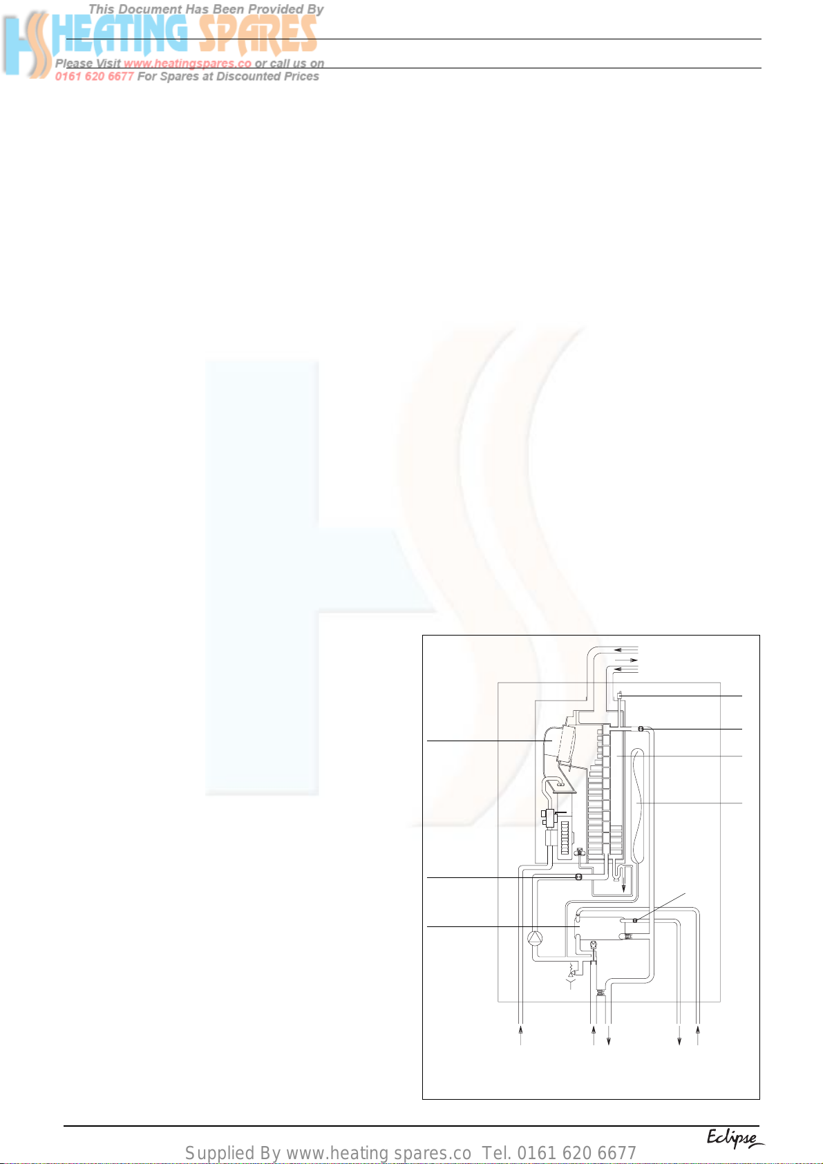
NTC2
(return sensor)
Domestic Heat
Exchanger
1
NTC1 (flow sensor)
Main Heat
Exchanger
Expansion
vessel
NTC 3
(inlet sensor)
1.4 CENTRAL HEATING MODE
When there is a request for heat via the time clock
and/or external controls the motorised valve and
pump will go through a self-test function this is to
ensure correct operation and valve configuration.
Once the self-test function is complete, the pump
and fan will activated via the flow temperature
sensor. When the fan is sensed to be operating
correctly, the ignition sequence commences. The
speed of the fan and therefore the output of the
Fig. 2
2
gas
return flow hw
outlet
cold
inlet
Page 5
Supplied By www.heating spares.co Tel. 0161 620 6677
SECTION 2 TECHNICAL DATA
2.1 Central heating
Heat input 29,00 kW
Maximum heat output 60/80°C (return & flow temperature) 25,3 kW
Maximum heat output 30/50°C (return & flow temperature) 26,8 kW
Minimum heat output 60/80°C (return & flow temperature) 7,3 kW
Minimum heat output 30/50°C (return & flow temperature) 8,10 kW
Minimum working pressure 0,45 bar
Maximum working pressure 3 bar
Minimum flow rate 350 l/h
2.2 Domestic hot water
Maximum input 29,00 kW
Maximum output 25,3 kW
Minimum output 8,1 kW
Flow rate (35°C rise) 10,4 l/min
Maximum inlet pressure 6,0 bar
Minimum inlet pressure to operate 0,15 bar
Minimum flow rate to operate 2,5 l/min.
2.3 Gas pressure Maximum
Inlet pressure (G20) 20,0 mbar
Maximum gas rate 2,76 m3/h
Minimum gas rate 0,80 m3/h
Injector size single injector with six 3,8 mm holes
2.4 Expansion vessel
Capacity 8 litres
Maximum system volume 76 litres
Pre-charge pressure 1,0 bar
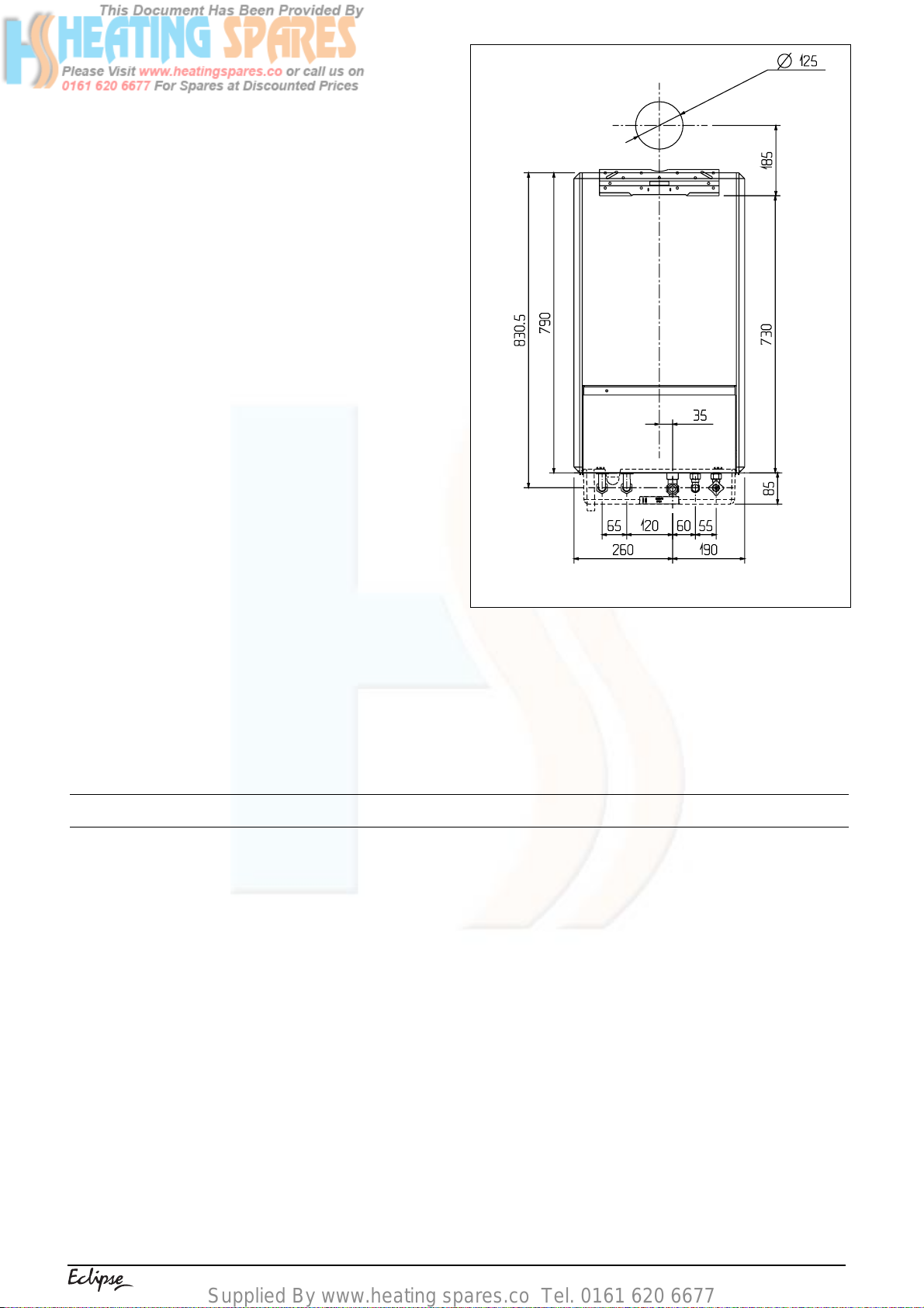
2.5 Dimensions
Height 790 mm
Width 450 mm
Depth 322 mm
Dry weight 57 kg
2.6 Clearances
Sides 25 mm
Top
Bottom 150 mm
Front 600 mm
2.7 Connections
Flow & return 22 mm compression
Hot & cold water 15 mm compression
Gas 1/2 inch BSP
Safety valve 1/2 inch BSP
2.8 Electrical
Voltage 230V/~ 50hz
Power consumption 130 W
Internal fuse 2 A
External fuse 3 A
2.9 Flue details
Maximum horizontal flue length (concentric) 6,45 metres
Maximum vertical flue length (concentric) 7,45 metres
Maximum twin flue length (horizontal or vertical) 29 m + 29 m
2.10 Efficiency
SEBDUK rating Band “A”
150 mm from casing or 25mm above flue elbow (whichever is applicable)
Ref. Condition 15 °C , 1013,25 mbar, dry gas
NOTE: L.P.G. data refer to section 10
3
Page 6
Supplied By www.heating spares.co Tel. 0161 620 6677
2.11 Adjustable operating parameters
PARAMETER MINIMUM MAXIMUM FACTORY SETTING
Maximum fan speed (HW mode) Fixed Fixed 5.500 RPM
Maximum fan speed (CH mode) See fig. 32 See fig. 32 5.500 RPM
Minimum fan speed Fixed Fixed 1.700 RPM
Soft-light fan speed Fixed Fixed 4.400 RPM
Pre-heat Fixed Fixed 55°C
Pre-heat temperature drop 5°C30°C20°C
Anti-cycle delay 0 seconds 306 seconds 92 seconds
Central heating flow temperature 20°C90°C75°C
Hot water outlet temperature 40°C65°C65°C
Pump over-run 3 m 99 m 10 m
2.12 Emissions MIN. OUTPUT MAX. OUTPUT
NO
x
15 ppm 30 ppm
CO 50 ppm 50 ppm
CO
2
9,8% 9,8%
CO/CO2 ratio 0.0005 to 1 0.0005 to 1
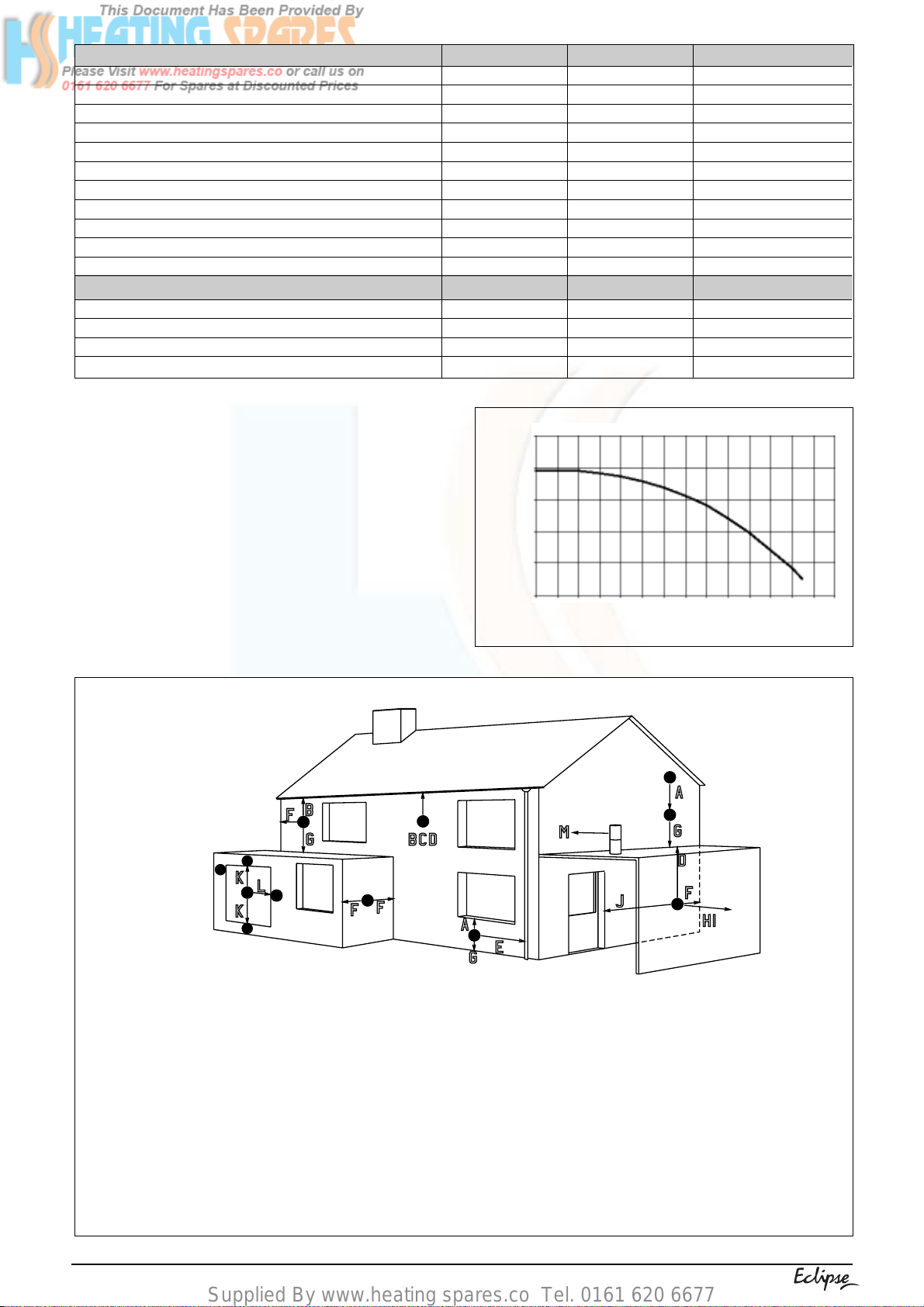
2.13 PUMP DUTY
Fig. 3 shows the flow rate available – after allowing
for pressure loss through the appliance – for
system requirements. When using this graph
apply only the pressure loss of the system. The
graph is based on 20°C temperature differential.
600
500
400
300
200
100
Water pressure (mbar)
0 100 200 300 400 500 600 700 800
Fig. 3
Litres Per Hour (x100)
900 1000
1100 1200 1300 1400
Terminal position for fan assisted boiler
(minimum distance) mm
A - Directly above or below an open window 300
J - From an opening in the car port (e.g. door
or other opening (e.g. air brick)
B - Below gutters, soil pipes or drain pipes 25
C - Below eaves 25
D - Below balconies or car port roof 25
E - From vertical drain pipes and soil pipes 75
K - Vertically from a terminal on the same wall 1500
L - Horizontally from a terminal on the same wall 300
M - Horizontally from a vertical terminal to a wall 300
N – Horizontally from an opening, airbric k,
F - From internal or external corners 25
G - Above ground or below balcony level 300
H - From a surface facing a terminal 600
I - From a terminal facing a terminal 1200
NOTE:The flue must be terminated in a place not likely to cause a
nuisance.
Fig. 4
4
window) into dwelling. 1200
openable window, etc. 300
Page 7
Supplied By www.heating spares.co Tel. 0161 620 6677
SECTION 3 GENERAL REQUIREMENTS
This appliance must be installed by a competent
person in accordance with the Gas Safety (Installation & Use) Regulations.
3.1 RELATED DOCUMENTS
The installation of this boiler must be in accordance with the relevant requirements of the Gas
Safety (Installation & Use) Regulations, the local
building regulations, the current I.E.E. wiring
regulations, the bylaws of the local water
undertaking, the Building Standards (Scotland)
Regulation and Building Standards (Northern
Ireland) Regulations.
It should be in accordance also with any relevant
requirements of the local authority and the relevant
recommendations of the following British Standard
Codes of Practice.
3.2 LOCATION OF APPLIANCE
The appliance may be installed in any room or
internal space, although particular attention is
drawn to the requirements of the current I.E.E.
wiring regulations, and in Scotland, the electrical
provisions of the Building Regulations, with
respect to the installation of the appliance in a
room or internal space containing a bath or shower.
for this purpose. An existing compartment/cupboard may be utilised provided that it is modified
to suit.
Details of essential features of compartment/
cupboard design, including airing cupboard installations, are given in BS 6798. This appliance
is not suitable for external installation.
3.3 GAS SUPPLY
The gas meter – as supplied by the gas supplier
– must be checked to ensure that it is of adequate
size to deal with the maximum rated input of all
the appliances that it serves. Installation pipes
must be fitted in accordance with BS 6891.
Pipe-work from the meter to the appliance must
be of adequate size. Pipes of a smaller size than
the appliance gas inlet connection must not be
used.
The installation must be tested for soundness in
accordance with BS 6891.
If the gas supply serves more than one appliance,
it must be ensured that an adequate supply is
maintained to each appliance when they are in
use at the same time.
BS 5440 PART 1 FLUES
BS 5440 PART 2 FLUES AND VENTILATION
BS 5449 PART 1 FORCED CIRCULATION HOT WATER SYSTEMS
BS 5546 INSTALLATION OF GAS HOT WATER SUPPLIES FOR DOMESTIC PURPOSES
(2ND FAMILY GASES)
BS 6798 BOILERS OF RATED INPUT NOT EXCEEDING 60kW
BS 6891 LOW PRESSURE INSTALLATION PIPES
BS 7074 PART 1 APPLICATION, SELECTION, AND INSTALLATION OF EXPANSION VESSELS AND
ANCILLARY EQUIPMENT FOR SEALED WATER SYSTEMS
When an appliance is installed in a room or
internal space containing a bath or shower, the
appliance or any control pertaining to it must not
be within reach of a person using the bath or
shower.
The location chosen for the appliance must permit
the provision of a safe and satisfactory flue and
termination. The location must also permit an
adequate air supply for combustion purposes
and an adequate space for servicing and air
circulation around the appliance.
Where the installation of the appliance will be in
an unusual location special procedures may be
necessary, BS 6798 gives detailed guidance on
this aspect.
A compartment used to enclose the appliance
must be designed and constructed specifically
3.4 FLUE SYSTEM
The terminal should be located where the dispersal of combustion products is not impeded and
with due regard for the damage and discoloration
that may occur to building products located
nearby.
The terminal must not be located in a place where
it is likely to cause a nuisance (see fig. 4).
Water vapour will condense on leaving the flue
terminal, the effect of such pluming must be
considered.
5
Page 8
Supplied By www.heating spares.co Tel. 0161 620 6677
If installed less than 2m above a pavement or
platform to which people have access (including
balconies or flat roofs) the terminal must be
protected by a guard of durable material. The
guard must be fitted centrally over the terminal.
Refer to BS 5440 Part 1, when the terminal is 0,5
metres (or less) below plastic guttering or 1 metre
(or less) below painted eaves.
3.5 AIR SUPPLY
The following notes are intended for general guidance
only.
This appliance is a room sealed, fan-flued boiler,
consequently it does not require a permanent air vent
for combustion air supply.
When installed in a cupboard or compartment, ventilation for cooling purposes is also not required.
3.6 WATER CIRCULATION
Detailed recommendations are given in BS 5449
Part 1 and BS 6798. The following notes are for
general guidance only.
3.6.1 PIPEWORK
It is recommended that copper tubing to BS 2871 Part
1 is used in conjunction with soldered capillary joints.
Where possible pipes should have a gradient to
ensure air is carried naturally to air release points
and that water flows naturally to drain cocks.
Except where providing useful heat, pipes should
be insulated to avoid heat loss and in particular to
avoid the possibility of freezing. Particular attention should be paid to pipes passing through
ventilated areas such as under floors, loft-space,
and void areas.
3.6.2 AUTOMATIC BY-PASS
The appliance has a built-in automatic by-pass,
consequently there is no requirement for an external by-pass, however the design of the system
should be such that it prevents boiler ‘cycling’.
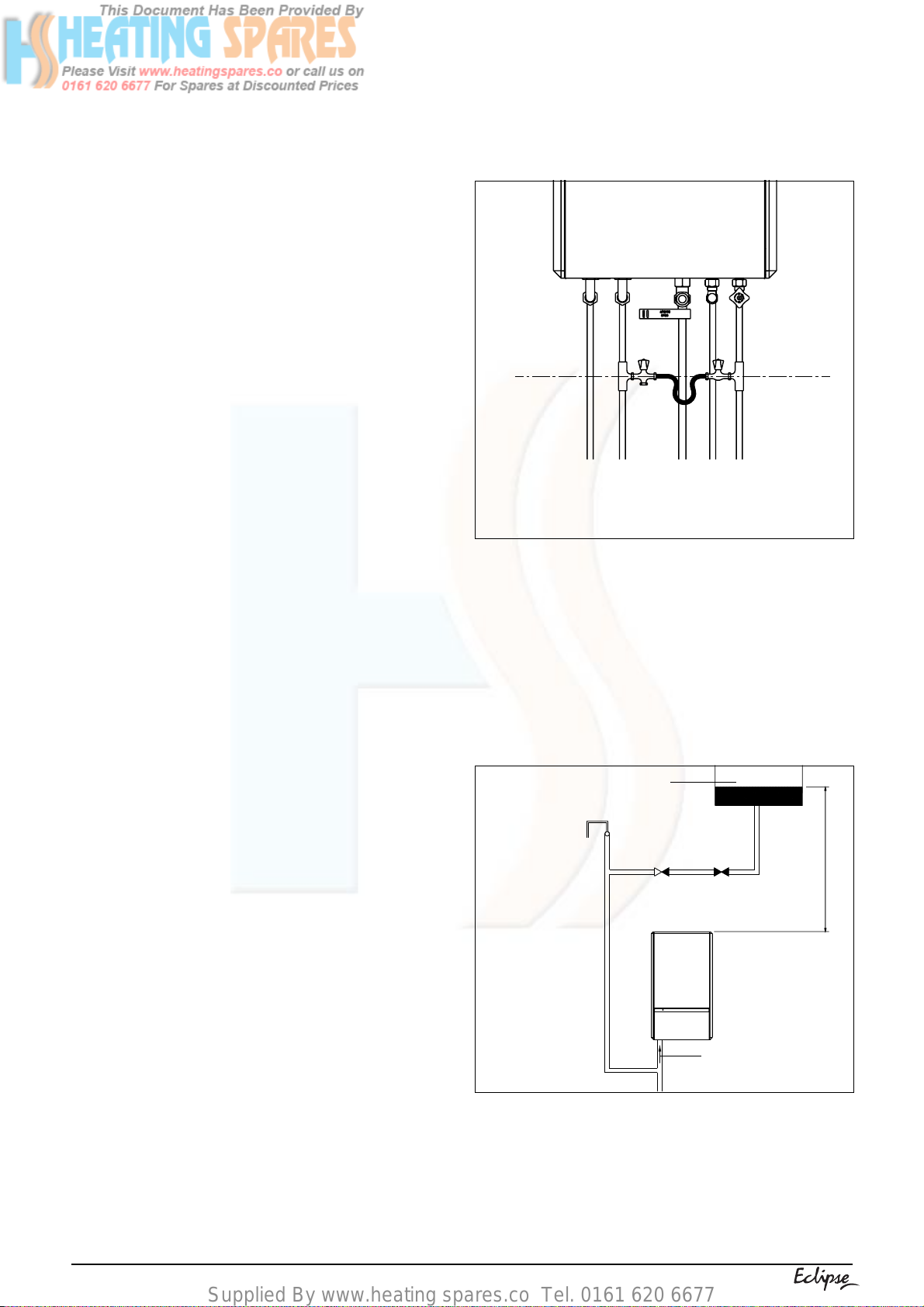
3.6.6 FILLING POINT
A method for initial filling of the system and
replacing water lost during servicing etc. must be
provided. This method of filling must comply with
the local water authority regulations.
Fig. 5 shows a widely accepted method.
Fig. 5
3.6.7 LOW PRESSURE SEALED SYSTEM
An alternative method of filling the system would
be from an independent make-up vessel or tank
mounted in a position at least 1 metre above the
highest point in the system and at least 5 metres
above the boiler (see fig. 5 A). The cold feed from
the make-up vessel or tank must be fitted with an
approved non-return valve and stopcock for isolation purposes. The feed pipe should be connected to the return pipe as close to the boiler as
possible.
Make-up vessel
or tank
Automatic
air-vent
3.6.3 DRAIN COCKS
These must be located in accessible positions to
facilitate draining of the appliance and all water pipes
connected to the appliance. The drain cocks must be
manufactured in accordance with BS 2879.
3.6.4 AIR RELEASE POINTS
These must be positioned at the highest points in
the system where air is likely to be trapped. They
should be used to expel trapped air and allow
complete filling of the system.
3.6.5 EXPANSION VESSEL
The appliance has an integral expansion vessel to
accommodate the increased volume of water when
Fig. 5 A
3.6.8 FREQUENT FILLING
the system is heated. It can accept up to 8 litres of
expansion from within the system, generally this is
sufficient, however if the system has an unusually high
water content, it may be necessary to provide additional
expansion capacity (see 6.19).
6
Non-return
valve
Stopcock
5.0 metres minimum
Heating
return
Frequent filling or venting of the system may be
indicative of a leak. Care should be taken during
the installation of the appliance to ensure all
aspects of the system are capable of withstanding pressures up to at least 3 bar.
Page 9
Supplied By www.heating spares.co Tel. 0161 620 6677
3.7 ELECTRICAL SUPPLY
The appliance is supplied for operation on 230V
@ 50Hz electrical supply, it must be protected
with a 3-amp fuse. The method of connection to
the mains electricity supply must allow for
complete isolation from the supply. The preferred
method is by using a double-pole switch with a
contact separation of at least 3mm. The switch
must only supply the appliance and its
corresponding controls, i.e. time clock, room thermostat, etc. Alternatively an un-switched shuttered
socket with a fused 3-pin plug both complying
with BS 1363 is acceptable.
3.8 SHOWERS
If the appliance is intended for use with a shower,
the shower must be thermostatically controlled
and be suitable for use with a combination boiler.
3.9 MOUNTING ON A COMBUSTIBLE SURFACE
If the appliance is to be fitted on a wall of combustible material, a sheet of fireproof material must
protect the wall.
3.10 TIMBER FRAMED BUILDINGS
If the appliance is to be fitted in a timber framed
building, it should be fitted in accordance with the
Institute of Gas Engineers publication (IGE/UP/
7) “Guide for Gas Installations in Timber Frame
Buildings”.
3.11 CONDENSATE DISPOSAL
When choosing a location for the boiler,
consideration should be given to the disposal of
the condensate discharge into a suitable drain or
soil pipe. The condensate outlet pipe must be
connected to the drain in accordance with building
regulations or other rules in force.
SECTION 4 INSTALLATION
4.1 DELIVERY
The appliance is delivered in a heavy-duty cardboard carton. Lay the carton on the floor with the
writing the correct way up.
4.2 CONTENTS
Contained within the carton is:
● the boiler;
● the wall mounting bracket;
● template;
● an accessories pack containing the appliance
service valves and washers;
● the instruction pack containing the installation
& servicing instructions, user instructions,
Benchmark logbook, guarantee registration
card, and a 3amp fuse.
4.3 UNPACKING
At the top of the carton pull both sides open – do
not use a knife – unfold the rest of the carton from
Fig. 6
3.12 INHIBITORS
The system shall be flushed in accordance with
BS 7593. If an inhibitor is to be used, it shall be
from a reputable manufacturer and shall be
administered in strict accordance with the
manufacturers instructions.
around the appliance, carefully remove all protective packaging from the appliance, and lay the
accessories etc. to one side.
4.4 PREPARATION FOR MOUNTING THE
APPLIANCE
The appliance should be mounted on a smooth,
vertical, non-combustible surface, which must be
capable of supporting the full weight of the
appliance. Care should be exercised when
determining the position of the appliance with
respect to hidden obstructions such as pipes,
cables, etc.
When the position of the appliance has been
decided – using the template supplied – carefully
mark the position of the wall-mounting bracket
(see fig. 6) and flue-hole (if applicable).
7
Page 10
Supplied By www.heating spares.co Tel. 0161 620 6677
4.5 FITTING THE FLUE
The top flue outlet permits both horizontal and
vertical flue applications to be considered,
alternatively, the Vokera twin flue system can be
utilised if longer flue runs are required.
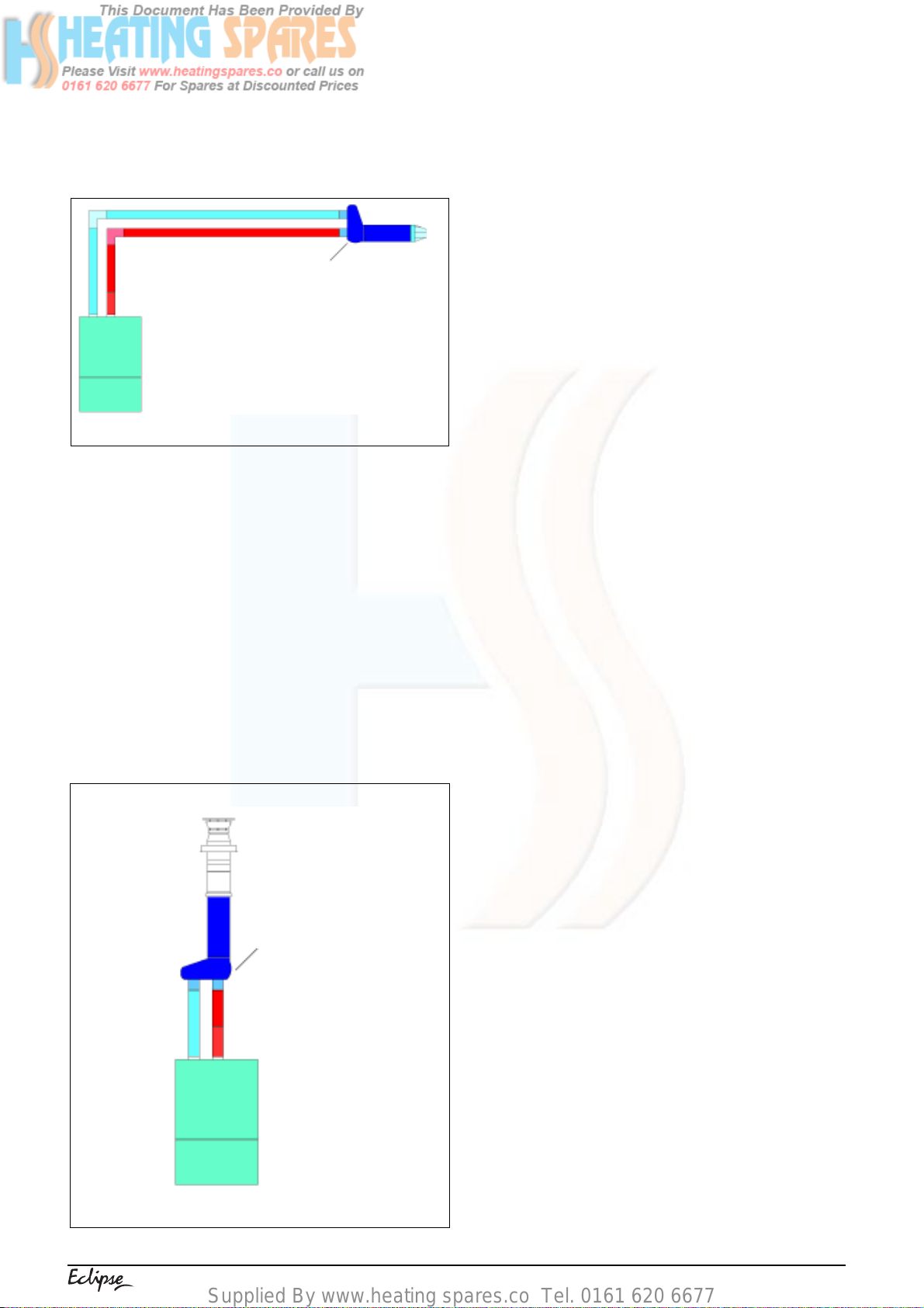
4.5.1 CONCENTRIC HORIZONTAL FLUE
(For concentric vertical flue, see 4.5.2).
(For twin flue applications, see 4.5.3).
The appliance flue outlet elbow can be rotated
through 360° on its vertical axis. In addition the
flue may be extended from the outlet elbow in the
horizontal plane (see 2.9). A reduction must also
be made to the maximum length (see table below)
when additional bends are used.
Reduction for additional bends
Bend
Reduction in maximum flue length for each bend
Take the large black gasket - supplied with the
flue terminal kit - and stretch it over the appliance
flue outlet (fig. 7). Using a twisting motion, connect
the boiler top adaptor - supplied with the flue
terminal kit - to the appliance flue outlet ensuring
the male spigot of the adaptor is pushed fully into
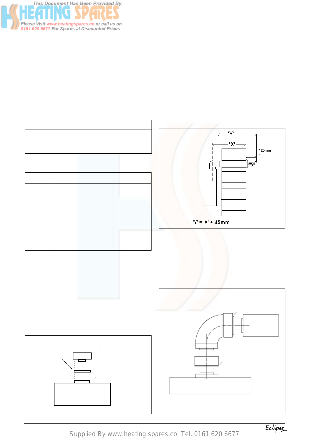
the flue outlet spigot of the boiler (fig. 7). Carefully
measure the distance from the centre of the
appliance flue outlet to the edge of the finished
outside wall (dimension X). Add 45mm to
dimension X to give you Dimension Y (see fig
7A). Measure dimension Y from the terminal end
of the concentric flue pipe and cut off the excess.
Pass the concentric flue pipe through the
previously drilled hole. Fit the flue bend to the boiler
top adaptor and insert the concentric flue pipe into
the flue bend ensuring the correct seal is made.
45° bend
90° bend
Part No.
0225720
0225755
0225740
0225745
0225750
0225730
0225735
0225760
0,5 metre
1,0 metre
Horizontal flue terminals and accessories
Description
Horizontal flue kit for use with
add. bends & extensions
350-500 T elescopic extension
0,5m extension
1,0m extension
2,0m extension
45° bend (pair)
90° bend
Wall bracket (5)
Min-Max length
1000mm
350mm-500mm
500mm
1000mm
2000mm
N/A
N/A
N/A
Using the template provided (see fig. 6), mark
and drill a 125mm hole for the passage of the
flue pipe. The hole should ha ve a 1° rise from the
boiler to outside.
Fig. 7A
NOTE
You must ensure that the entire flue system is
properly supported and connected.
Seal the flue assembly to the wall using cement
or a suitable alternative that will provide
satisfactory weatherproofing. The interior and
exterior trim can now be fitted.
The fixing holes for the wall-mounting bracket
should now be drilled and plugged, an
appropriate type and quantity of fixing should be
used to ensure that the bracket is mounted
securely. Once the bracket has been secured to
the wall, mount the appliance onto the brack et.
FITTING THE HORIZONTAL FLUE KIT
Boiler top
Black
adaptor
gasket
Flue outlet
Boiler
Fig. 7
8
Fig. 7B
Boiler
Push-fit
connection
Boiler top
adaptor
Extension
Page 11
Supplied By www.heating spares.co Tel. 0161 620 6677
4.5.1.1 EXTENDING THE FLUE
Connect the bend – supplied with the terminal kit
– to the top of the boiler using the boiler top
adapter (supplied, see fig. 7). The additional
bends & extensions have push-fit connections,
care should be taken to ensure that the correct
seal is made when assembling the flue system.
Connect the required number of flue extensions
or bends (up to the maximum equivalent flue
length) to the flue terminal (see fig. 7B & 7C).
NOTE
When cutting an extension to the required length,
you must ensure that the excess is cut from the
plain end of the extension (see fig. 7B & 7C).
Remove any burrs, and check that any seals are
located properly.
You must ensure that the entire flue system is
properly supported and connected.
Push-fit connection
Plain end
Extension pipe
Boiler top adaptor
Vertical flue terminal and accessories
Part No.
0225725
0225770
0225765
0225755
0225740
0225745
0225750
0225730
0225735
0225760
Description
Vertical flue terminal
Pitched roof flashing plate
Flat roof flashing plate
350-500 telescopic extension
0,5m extension
1,0m extension
2,0m extension
45° bend (pair)
90° bend
Wall bracket (4)
Min-Max length
1000 mm
N/A
N/A
350mm-500mm
500mm
1000mm
2000mm
N/A
N/A
N/A
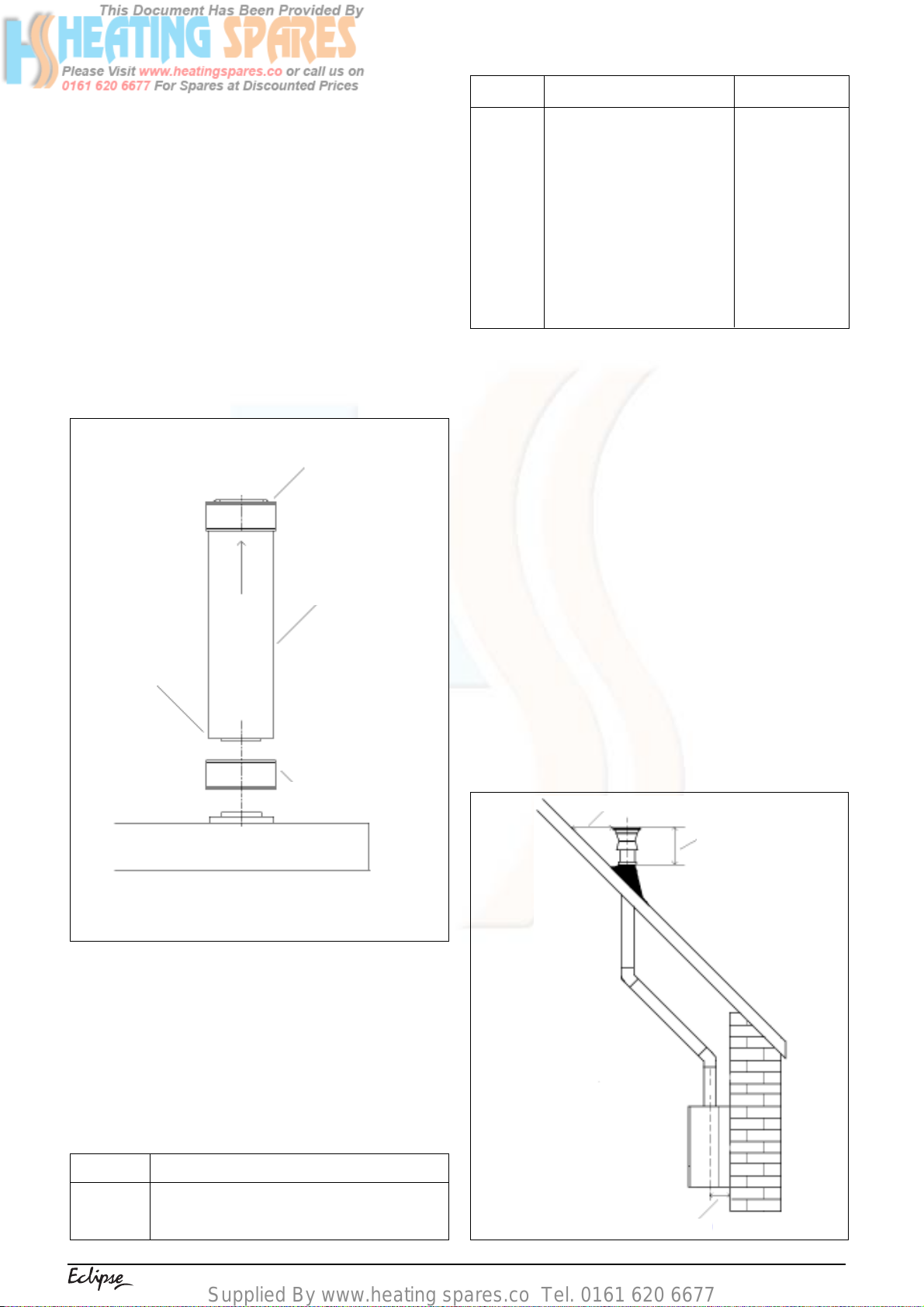
Using the dimensions given in fig. 8 as a reference,
mark and cut a 105mm hole in the ceiling and/or roof.
IMPORTANT
You must ensure that the terminal is at least
300mm from any structure or surface (see fig. 8).
The vertical flue terminal is 1,0 metre in length
and cannot be cut; therefore it may be necessary
to adjust the height of the appliance to suit or use
a suitable extension.
Encure that any horizontal sections of the flue
system have a 1° fall back to the boiler (17mm per
1000mm).
Fit the appropriate flashing plate to the roof and
insert the vertical flue terminal through the flashing
plate from the outside, ensuring that the collar on
the flue terminal fits over the flashing.
The fixing holes for the wall-mounting bracket
should now be drilled and plugged, an appropriate
type and quantity of fixing should be used to
ensure that the bracket is mounted securely.
Once the bracket has been secured to the wall,
mount the appliance onto the bracket.
300mm minimum
Boiler
Fig. 7C
4.5.2 CONCENTRIC VERTICAL FLUE
The vertical flue terminal can be connected directly
to the appliance flue outlet. Alternatively, an
extension or bend can be connected to the
appliance flue outlet if desired (see 2.9), however
if additional bends are fitted, a reduction must be
made to the maximum flue length (see table
below).
Reduction for bends
Bend
45° bend
90° bend
Reduction in maximum flue length for each bend
0,5 metre
1,0 metre
Fig. 8
520mm
139mm
9
Page 12
Supplied By www.heating spares.co Tel. 0161 620 6677
NOTE
When cutting an extension to the required length,
you must ensure that the excess is cut from the
plain end of the extension.
Remove any b urrs, and check that an y seals are
located properly .
4.5.3 TWIN FLUE SYSTEM
The Vokera twin flue system enables greater flue
distances to be achieved (see 2.9) than that of the
standard concentric flue system. It can be used f or
horizontal or vertical applications, howev er the twin
flue system must be converted to the dedicated
concentric flue kit for termination. It is essential that
the installation of the twin flue system be carried
out in strict accordance with these instructions.
GUIDANCE NOTES ON TWIN FLUE
INSTALLATION
● The flue must hav e a f all back of 1° back to the
appliance to allow any condensate that forms
in the flue system to drain. Consideration must
also be given to the fact that there is the
possibility of a small amount of condensate
dripping from the terminal.
● Ensure that the entire flue system is adequately
supported, use at least one bracket for each
extension.
● As the exhaust outlet pipe can reach v ery high
temperatures it must be protected to prevent
persons touching the hot surface.
Reduction for bends
Bend
45° bend
90° bend
Reduction in maximum flue length for each bend
1,0 metre
1,0 metre
Twin flue accessories
Part No. Description
0225805
0225810
359
0225770
0225765
0225815
0225820
0225825
0225830
0225835
0225840
0225845
0225850
0225855
Horizontal flue terminal
Vertical flue terminal
Twin adapter kit
Pitched roof flashing plate
Flat roof flashing plate
Condensate drain kit
0,25m extension (pair)
0,5m extension (pair)
1,0m extension (pair)
2,0m extension (pair)
45° bend (pair)
90° bend (pair)
Twin bracket (5)
Single bracket (5)
MOUNTING THE BOILER
The fixing holes for the wall-mounting bracket
should now be drilled and plugged, an
appropriate type and quantity of fixing should be
used to ensure that the bracket is mounted
securely. Once the bracket has been secured to
the wall, mount the appliance onto the bracket.
Length
1000 mm
1000 mm
N/A
N/A
N/A
N/A
250mm
500mm
1000mm
2000mm
N/A
N/A
N/A
N/A
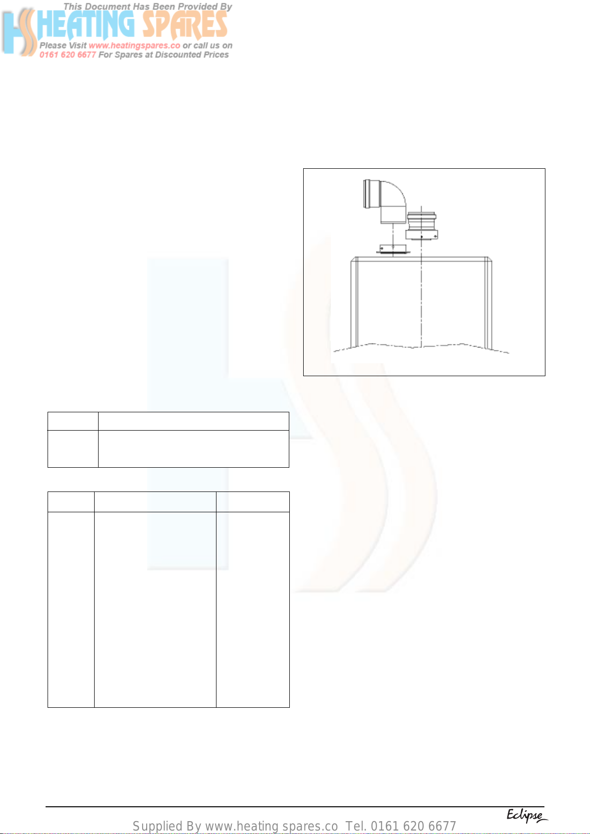
4.5.3.1 INSTALLATION OF TWIN ADAPTOR KIT (see fig. 9)
● Discard the restrictor ring (supplied with the twin
adapter kit).
● Insert the exhaust connection manifold onto the
appliance flue outlet.
● Place the silicone seal (supplied with twin
adapter kit) over the rim of the exhaust
connection manifold.
● Remove one of the blanking plate (located to
the left & right of the appliance flue outlet) and
– using the same screws – install the air baffle.
Fig. 9
4.5.3.2 HORIZONTAL TERMINATION (see fig. 10)
The twin flue system must be converted to the
dedicated concentric flue kit for termination.
● The horizontal terminal is supplied with a built-
in converter box and cannot be shortened.
● A 130mm hole is required for the passage of
the concentric terminal through the wall.
Depending on site conditions it may be pref erable
to install the terminal assembly prior to fitting the
twin flue pipes.
Mark and drill a 130mm hole for the passage of
the horizontal flue terminal, ensuring that there
is a 1° fall back to the boiler (17mm per 1000mm).
Insert the terminal assembly into the flue hole.
Push-fit the twin flue pipes onto the concentric to
twin converter box ensuring that the exhaust pipe
connects to the exhaust connection on the
concentric to twin converter.
If necessary cut the plain ends (male) of the twin
flue pipes to allow connection to the concentric
to twin converter.
NOTE
Before cutting twin flue pipes ensure allowances
have been made f or connection onto the previous
piece and onto the concentric to twin converter.
The last twin flue pipes must be pushed 50mm
onto the male spigots of the concentric to twin
converter.
NOTE
You must ensure that the entire flue system is
properly supported and connected.
When cutting an extension to the required length,
you should ensure that the excess is cut from
10
Page 13
Supplied By www.heating spares.co Tel. 0161 620 6677
the plain end of the extension. Remove an y burrs,
and check that both seals are located properly.
Seal the flue terminal assembly to the wall using
cement or a suitable alternative that will provide
satisfactory weatherproofing. The interior and
exterior trim can now be fitted.
convertor box
Fig. 10
Push-fit the twin flue pipes onto the concentric to
twin converter ensuring that the exhaust pipe
connects to the exhaust connection on the
concentric to twin converter.
If necessary cut the plain ends (male) of the twin
flue pipes to allow connection to the concentric
to twin converter.
NOTE
● Before cutting twin flue pipes ensure
allowances have been made for connection
onto the previous piece and onto the concentric
to twin converter. The last twin flue pipes must
be pushed 50mm onto the male spigots of the
concentric to twin converter.
● You must ensure that the entire flue system is
properly supported and connected.
● Ensure that any horizontal sections of pipe hav e
a 1° fall towards the appliance (17mm per
1000mm).
● The convertor box on the vertical terminal will
have to be temporarily remo ved when inserting
the terminal through the flashing.
4.5.3.3 VERTICAL TERMINATION (see fig. 11)
The twin flue system must be converted to the
dedicated concentric flue kit for termination.
● The vertical terminal is supplied with a built-in
converter box and cannot be shortened.
● A 130mm hole is required for the passage of
the concentric terminal through the ceiling and/
or roof.
Depending on site conditions it may be prefer able
to install the terminal assembly prior to fitting the
twin flue pipes.
Fit the appropriate flashing plate to the roof and
insert the vertical flue terminal through the
flashing plate from the outside, ensuring that the
collar on the flue terminal fits over the flashing.
convertor box
4.6 CONNECTING THE GAS AND WATER
The appliance is supplied with an accessories
pack that contains sealing washers and service
valves.
When connecting pipe work to the valves, tighten
the compression end first, then insert the sealing
washers before tightening the valve or connection
to the appliance.
NOTE
It will be necessary to hold the valve with one
spanner whilst tightening with another.
4.6.1 GAS (see fig. 12)
The appliance is supplied with a 1/2 inch BSP
service valve, connect the supply pipe to the inlet
of the valve and tighten the connecting nut.
NOTE
It will be necessary to calculate the diameter of
the gas pipe to ensure the appliance has an
adequate supply of gas.
4.6.2 FLOW & RETURN (see fig. 12)
The appliance is supplied with 22mm service
valves for the flow and return connections, connect
a 22mm pipe to the inlet of each valve and tighten
both nuts.
4.6.3 SAFETY VALVE (see fig. 12)
Fig. 11
Connect a suitable coupling and 15mm pipe to
the safety valve outlet and tighten.The discharge
pipe must have a continuous fall away from the
appliance to outside and allow any water to drain
away thereby eliminating the possibility of freezing.
The discharge pipe must terminate in a position
where any water - possibly boiling - discharges
safely without causing damage or injury, but is
still visible.
11
Page 14
Supplied By www.heating spares.co Tel. 0161 620 6677
4.6.4 COLD WATER INLET (see fig. 12)
The appliance is supplied with a 15mm service
valve, connect a 15mm pipe to the inlet of the
valve and tighten both nuts.
4.6.5 HOT WATER OUTLET (see fig. 12)
The appliance is supplied with a 15mm male
connector. Using a suitable coupling, connect a
15mm pipe to the supplied connector and tighten
the nut.
4.7 CONDENSATE OUTLET (see fig. 12)
During normal operation the boiler produces
condensate which is collected in a trap located in
the lower part of the boiler. A flexible pipe
(condensate outlet pipe) is connected to the
outlet of the trap. The flexible pipe must be
connected to a plastic waste pipe only. The
plastic waste pipe must have a minimum of a 3°
fall towards the drain. Any external run of pipe
should be insulated to prevent the risk of freezing.
CONNECTING THE CONDENSATE OUTLET
Gently pull the condensate outlet pipe down from
its location inside the boiler until approximately
250mm protrudes from the underside of the boiler.
Connect a suitable pipe (no less than 20mm
diameter) to the outlet pipe and ensure it
discharges in accordance with building regulations
or other rules in force.
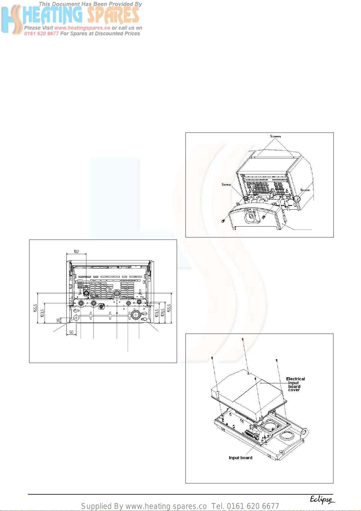
4.8.1 CASING REMOVAL
To gain access to the appliance electrical connections you must first remove the casing, proceed as follows:
● locate and remove the 2 screws that secure the
controls fascia to the appliance casing (see fig. 13).
● locate and remove the 2 screws that secure the
casing to the back frame of the boiler (see fig. 13).
● gently pull one side of the casing then the other
to disengage it from the retaining clips.
● lift the casing upward to disengage it from the
top locating hooks and then remove.
● store the casing and screws safely until required.
Re-fit in the reverse order.
Fig.13
Safety valve
outlet
Condensate
outlet pipe
Fig. 12
Return Gas
Flow
Cold water
inlet
4.8 ELECTRICAL CONNECTIONS
The electrical supply must be as specified in 3.7.
A qualified electrician should connect the electrical supply to the appliance. If controls - external
to the appliance - are required, a competent
person must undertake the design of any external
electrical circuits, please refer to section 8 for
detailed instructions.
ANY EXTERNAL CONTROL OR WIRING MUST
BE SERVED FROM THE SAME ISOLATOR AS
THAT OF THE APPLIANCE.
The supply cable from the isolator to the appliance
must be 3-core flexible sized 0,75mm to BS 6500.
Wiring to the appliance must be rated for operation in contact with surfaces up to 90°C.
4.8.2 ELECTRICAL INPUT BOARD
The appliance electrical input board is
located behind the control fascia (see fig.14).
Locate and remove the 4 screws securing
the input board cover.
NOTE
The appliance comes with a factory fitted link to
allow basic operation of the boiler via the keypad.
If it is anticipated that external controls will be
required please refer to the wiring diagrams in
section 8 for more detailed information.
Cable
entries
Hot water
outlet
Fig.14
12
Page 15

Supplied By www.heating spares.co Tel. 0161 620 6677
4.8.3 CONNECTING THE MAINS (230V) INPUT
(see fig. 15)
Remove the electrical input board cover as
described in 4.8.2. Pass the cable through the
cable anchorage (see fig. 6). Connect the supply
cable wires (earth, live, & neutral) to their
corresponding terminals on the electrical input
board. Ensure that the EARTH wire is left slightly
longer than the others, this will prevent strain on
the Earth wire should the cable become taut.
Do not remove the 24V link wire (between
terminals 2 & 3 on plug M4) unless additional
external controls are to be fitted (see section 8).
Re-fit the electrical input board cover.
The securing screw on the cable anchorage
should now be tightened. This must be done
before the control fascia is re-fitted in the upright
position. The appliance casing and screws can
now be re-fitted.
Fig. 15
13
Page 16

Supplied By www.heating spares.co Tel. 0161 620 6677
SECTION 5 COMMISSIONING
5.1 GAS SUPPLY INSTALLATION
Inspect the entire installation including the gas
meter, test for soundness and purge. Refer to BS
6891 for specific instruction.
5.2 THE HEATING SYSTEM
The appliance contains components that may
become damaged or rendered inoperable by oils
and/or debris that are residual from the installation of the system, consequently it is essential
that the system be flushed in accordance with the
following instructions.
5.3 INITIAL FILLING OF THE SYSTEM
Ensure both flow and return service valves are
open, remove appliance casing as described in
4.8.1, identify the automatic air release valve and
loosen the dust cap by turning cap anti-clockwise
one full turn. IMPORTANT, THERE ARE NO
MANUAL AIR RELEASE VALVES LOCATED
ON THE APPLIANCE. Ensure all manual air
release valves located on the heating system are
closed. Using the method of filling as described in
fig. 5, slowly proceed to fill the system. As water
enters the system the pressure gauge will begin
to rise. Once the gauge has reached 1 bar close
the filling valve and begin venting all manual air
release valves, starting at the lowest first. It may
be necessary to go back and top-up the pressure
until the entire system has been filled. Inspect the
system for water soundness, rectifying any leaks.
5.4 INITIAL FLUSHING OF THE SYSTEM
The whole of the heating system must be flushed
both cold and hot as detailed in 5.8. Open all
radiator or heating valves and the appliance flow
& return service valves. Drain the boiler and
system from the lowest points. Open the drain
valve full bore to remove any installation debris
from the boiler prior to lighting. Refill the boiler
and heating system as described in 5.3.
5.5 FILLING THE HOT WATER SYSTEM
Close all hot water outlets, turn appliance stopcock on (anti-clockwise), slowly open each outlet
until all air has been expelled and clear water is
discharged. Check pipe-work etc. for water
soundness.
● ensure the system has been filled, vented, and
the pressure set to 1 bar;
● ensure the flue system has been fitted properly
and in accordance with the instructions;
● ensure all appliance service valves are open.
5.7 INITIAL LIGHTING
Ensure the electrical supply to the appliance is
switched on. Switch the time clock or programmer
to an ‘on’ position and ensure all external controls
are also calling for heat.
The appliance will now operate in the pre-heat
mode as described in 1.2. Once the pre-heat
function has been completed, the appliance will
operate in the central heating mode as described
in 1.4. Should the appliance fail to ignite, refer to
5.6 and/or section 7 (fault finding).
5.8 FINAL FLUSHING OF THE HEATING SYSTEM
The system shall be flushed in accordance with
BS 7593. If a cleanser is to be used, it shall be
from a reputable manufacturer* and shall be
administered in strict accordance with the
manufacturers instructions.
*Both Sentinel and Fernox manufacture products
that have proved suitable for use with Vokera
appliances. Vokera Ltd. cannot comment on the
suitability of any other such product with our
appliances.
5.8.1 INHIBITORS
See 3.12
5.9 OPERATING PARAMETERS
The Eclipse boiler is supplied with built-in
parameter defaults (see 2.11), the following
procedure can be used if any parameters require
to be adjusted or changed.
● Press the MODE button until a FIXED decimal
point appears in LED 1 (see fig. 16).
● Press the STEP button until the desired
parameter is shown in LED 1.
● Using the +/- buttons, change the parameter
value (shown in LED 2).
● Press the STORE button to save the new value.
● Press the MODE button until no decimal point
is shown.
5.6 PRE-OPERATION CHECKS
Before attempting to initial lighting of the appliance, the following checks must be carried out:
● ensure all gas service valves from the meter to
the appliance are open and the supply pipe has
been properly purged;
● ensure the proper electrical checks have been
carried out, (see 7.7) particularly continuity,
polarity and resistance to earth;
● ensure the 3 amp fuse – supplied with the
appliance – has been fitted;
Fig. 16
14
Page 17

Supplied By www.heating spares.co Tel. 0161 620 6677
STEP
1
2
3
4
OPERATING PARAMETER
Hot water outlet temperature
Pre-heat temperature drop
Central heating mode
Central heating flow temperature
5.10 FUNCTIONAL PARAMETERS
These parameters should only be changed or
adjusted by the commissioning engineer or service
technician. To change or adjust the functional
parameters, it is necessary to access the
appliance engineer mode.
● Press and hold the MODE and STEP buttons
simultaneously, LED 1 should now show “C”
(see fig. 17).
● Whilst continuing to hold down the MODE and
STEP buttons, using the +/- buttons, adjust
LED 2 until it shows “33”.
● Press STORE.
● LED 2 will now flash twice, the MODE and
STEP buttons can now be released.
● Press the MODE button until it shows a FIXED
decimal point (see fig. 16).
● Press the STEP button until it shows the desired
parameter (LED 1).
● Adjust the value (LED 2) using the +/- buttons
● Press STORE to save the new setting.
● Press the RESET button to exit the appliance
engineer mode.
IMPORTANT
Under no circumstances should any parameters
- other than those shown above - be changed or
adjusted.
Please refer to section 7 before making any
adjustments to the fan speed parameters of the
boiler.
5.11 RANGE RATING
The output of the boiler is automatically adjusted
by a continuous air/gas modulation system. The
system is controlled by the NTC thermistors (flow
VALUE
Variable between 40°-65°C
DEFAULT SETTING
60°C
02 = 5°C
03 = 10°C
04 = 20°C
04 = 20°C
05 = 30°C
00 = off
01 = on
01 = on
Variable between 20° 90°C
75°C
Fig. 17
& return temperature sensors) which ensures
stability of temperature irrespective of load
conditions. However the appliance also has a
range rating facility which can be used to limit the
maximum output - to central heating - if required.
Please refer to section 7 for more details.
5.12 SETTING THE SYSTEM DESIGN PRESSURE
The design pressure should be a minimum of 1
bar and a maximum of 1,5 bar.
The actual reading should ideally be 1 bar plus
equivalent height in metres (0,1 bar = 1 metre) to
the highest point in the system above the base of
the appliance (up to the maximum of 1,5 bar total).
N.B. The safety valve is set to lift at 3 bar/30
metres/45 psig.
To lower the system pressure to the required
value, pull lever on head of safety valve to release
water until the required figure registers on the
pressure gauge (see fig. 1).
STEP
A
OPERATING PARAMETER
Anty-cycle
VALUE DEFAULT SETTING
Variable between 0-30
(where 1=10,2 seconds)
b
Pump over-run
Variable between 3-99
(where 1=1 minute)
I
CH delay after HW request
Variable between 0-30
(where 1=10,2 seconds)
J
CH fan speed (maximum)
Variable between 17-55
(where 1=100 RPM)
L
n
DHW fan speed (maximum)
Minimum fan speed (CH & DHW)
Fixed
Variable between 16-55
(where 1=100 RPM)
o
Soft-light fan speed
Variable between 1-100
(where 1=1%)
9 (91,8 seconds)
10 (10 minutes)
3 (30,6 seconds)
55 (5500 RPM)
55 (5500 RPM)
17 (1700 RPM)
80 (%)
15
Page 18

Supplied By www.heating spares.co Tel. 0161 620 6677
5.13 REGULATING THE CENTRAL HEATING
SYSTEM
Fully open all radiator and circuit valves and run
the appliance for both heating and hot water until
heated water is circulating. If conditions are warm
remove any thermostatic heads. Adjust radiator
return valves and any branch circuit return valves
until the individual return temperatures are correct
and are approximately equal.
5.14 FINAL CHECKS
● ENSURE ALL TEST NIPPLES ON THE AP-
PLIANCE GAS VALVE ARE TIGHT AND HAVE
BEEN CHECKED FOR SOUNDNESS.
● ENSURE THE APPLIANCE FLUE SYSTEM IS
FITTED CORRECTLY AND IS PROPERLY
SECURED.
● ENSURE ALL PIPE WORK IS RE-CHECKED
FOR SOUNDNESS.
● RE-FIT APPLIANCE CASING.
● COMPLETE APPLIANCE LOGBOOK.
Complete details of the boiler, controls, installation and commissioning in the logbook supplied
with the boiler. This is an important document,
which must be correctly completed and handed
to the user. Failure to install and commission the
appliance to the manufacturers instructions may
invalidate the warranty.
5.15 INSTRUCTING THE USER
Hand over all documentation supplied with this
appliance – including these instructions – and
explain the importance of keeping them in a safe
place.
Explain to the user how to isolate the appliance
from the gas, water, and electricity supplies, and
the locations of all drain points.
Show the user how to operate the appliance and
its associated controls correctly.
Show the user the location of the filling valve and
how to top-up the system pressure correctly, and
show the location of all manual air release points.
Explain to the user how to turn off the appliance
for both long and short periods, and advise on the
necessary precautions to prevent frost damage.
16
Page 19

Supplied By www.heating spares.co Tel. 0161 620 6677
SECTION 6 SERVICING INSTRUCTIONS
6.1 GENERAL
To ensure the continued safe and efficient operation of the appliance, it is recommended that it is
checked and serviced at regular intervals.
The frequency of servicing will depend upon the
particular installation conditions, but in general,
once per year should be adequate.
It is the law that any servicing work is carried out
by a competent person such as a Vokera engineer,
an approved service agent, British Gas, or other
CORGI registered personnel.
The following instructions apply to the appliance
and its controls, but it should be remembered that
the central heating system will also require
attention from time to time.
6.2 ROUTINE ANNUAL SERVICING
● Check the operation of the appliance and ensure
it functions as described in section 7.
● Compare the performance of the appliance
with its design specification. The cause of any
noticeable deterioration should be identified
and rectified without delay.
● Thoroughly inspect the appliance for signs of
damage or deterioration especially the flue
system and the electrical apparatus.
● Check and adjust – if necessary – the system
design pressure (see 5.12).
● Ensure both the burner and heat exchanger are
clean and free from any debris or obstruction.
● Carry out an analysis of the flue gases (see
7.4), and visually check the condition of the
entire flue assembly.
● Compare the results with the appliance design
specification. Any deterioration in performance
must be identified and rectified without delay.
● Inspect all joints for signs of leakage and repair
if necessary.
● Refer to the commissioning section and/or re-
placement of parts section for detailed
instruction if required.
6.3 REPLACEMENT OF COMPONENTS
Although it is anticipated that this appliance will
give years of reliable, trouble free service, the life
span of components will be determined by factors
such as operating conditions and usage. Should
the appliance develop a fault, the fault finding
section will assist in determining which component
is malfunctioning.
some water absorbent cloths are available to
catch any residual water that may drip from the
appliance or removed component. Undertake a
complete commissioning check as detailed in
section 5, after replacing any component.
ALWAYS TEST FOR GAS SOUNDNESS IF
ANY GAS CARRYING COMPONENTS HAVE
BEEN REMOVED OR DISTURBED.
6.5 PUMP HEAD (see fig. 18)
Carry out component removal procedure as described in 6.4.
Using a 4mm Allen key or ‘T’ bar, unscrew and
remove the four Allen screws that hold the pump
in position, pull firmly on the pump head to release
it from the base. Disconnect the electrical leads.
Replace in the reverse order.
Pump
head
Fig. 18
6.6 SAFETY VALVE (see fig. 19)
Carry out component removal procedure as described in 6.4.
Disconnect the outlet pipe from the safety valve.
Remove safety valve locking screw from the
underside of the appliance manifold.
Replace in the reverse order.
6.7 AUTOMATIC AIR RELEASE VALVE (AAV)
Carry out component removal procedure as described in 6.4.
Using a suitable pair of pump pliers, unscrew the
AAV from its position.
Replace in the reverse order.
6.4 COMPONENT REMOVAL PROCEDURE
To remove a component, access to the interior of
the appliance is essential. Isolate the appliance
from the electrical supply and remove the fuse.
And when necessary, close all service valves on
the appliance, remove the appliance casing as
described in section 4.8.1. Drain the water content
from the appliance via the safety valve. Ensure
Fig. 19
Safety valve
Locking screw
17
Page 20

Supplied By www.heating spares.co Tel. 0161 620 6677
6.8 PRESSURE GAUGE (see fig. 20)
Carry out component removal procedure as described in 6.4.
Remove pressure gauge locking screw, located
on manifold, and withdraw the pressure gauge
pipe, locate the spring tabs on the pressure
gauge body, push and hold tabs in, to enable
extraction of the gauge from its location.
Replace in the reverse order.
Manifold
Pressure gauge
connection
Locking screw
Fig. 20
6.9 NTC THERMISTORS (temperature sensors)
Carry out component removal procedure as described in 6.4.
Cold water inlet sensor (see fig. 21)
Disconnet thermistor electrical plug. Using a
13mm spanner slacken and remove the thermistor
and sealing washer.
Replace in the reverse order.
Screw
Screw
Fig. 22
6.10 PRINTED CIRCUIT BOARD (PCB) (see fig. 23)
Carry out component removal procedure as described in 6.4.
● Locate and remove the 4 screws that secure
the PCB housing cover, then remove cover.
● After carefully taking note of all wiring
connections, disconnect all wiring from the
PCB.
● Locate and remove the PCB housing securing
screws, remove PCB housing.
● Remove the 4 screws that secure the
transformer to the PCB housing.
● Locate and remove the 3 screws that secure
the PCB to the housing.
Replace in the reverse order.
Housing
P.C.B.
Cover
Actuator
locking pin
Actuator
Fig. 21
Cold water
inlet sensor
Flow & return sensors (see fig. 1 & 22)
Pull back protective boot and remove the 2 spade
connectors. Slacken and remove the 2 securing
screws.
Replace in the reverse order.
Fig. 23
6.11 GAS VALVE (see fig. 24)
Carry out component removal procedure as described in 6.4.
The gas valve must be changed as complete unit.
Unclip and remove the air chamber cover.
Disconnect the electrical plug from the gas valve.
Disconnect silicone tube from gas valve regulator.
Slacken and unscrew gas valve inlet and outlet
connections. Please note, the sealing washers
must be discarded and replaced with new sealing
washers. The gas valve can now be removed.
Replace in the reverse order. Refer to section
seven for detailed instructions on how to set-up
the gas valve. WARNING, A GAS SOUNDNESS
CHECK MUST BE CARRIED OUT.
18
Page 21

Supplied By www.heating spares.co Tel. 0161 620 6677
6.12 FAN (see fig. 24)
Carry out component removal procedure as described in 6.4.
Unclip and remove the air chamber cover.
Disconnect the electrical plug from the fan.
Locate and remove the 4 bolts that secure the fan
to the pre-mix manifold.
Replace in reverse order.
Silicone
tube
Outlet
All dimensions in mm.
Pre-mix manifold
Gas
valve
Inlet
Fig. 24
Fan securing bolts
6.13 BURNER (see fig. 25)
Carry out component removal procedure as described in 6.4.
Unclip and remove the air chamber cover.
Locate and remove the 8 nuts (10mm) securing
the pre-mix manifold/burner assembly.
Disconnect the gas valve outlet pipe at its
connection to the pre-mix manifold. Disconnect
the silicone pipe from the pre-mix manifold. Gently
pull away the fan/pre-mix manifold assembly
from the heat exchanger. Remove the earth wire
from the burner earth tab and gently lift the burner
from its location.
Replace in the reverse order. Please note, ensure
all seals are in good condition, taking care to
ensure they are replaced correctly.
Fan
Fig. 26
6.14 ELECTRODE (see fig. 25 & 26)
Carry out component removal procedure as described in 6.4.
Unclip and remove the air chamber cover.
Remove the electrode lead. Remove the 2 screws
that secure the electrode to the combustion cover,
and gently withdraw the electrode.
Replace in the reverse order, ensuring that the
electrode seal is in good condition and that the
combustion cover insulation board is undisturbed.
6.15 INJECTOR (see fig. 27)
Carry out component removal procedure as described in 6.4.
Unclip and remove the air chamber cover.
Remove the fan as detailed in 6.12 using a 17mm
socket, locate and unscrew the injector.
Replace in the reverse order.
Securing nuts
Spark
electrode
Fig. 27
Fig. 25
Gas valve outlet
connection
Burner plate
Injector
Fan
19
Page 22

Supplied By www.heating spares.co Tel. 0161 620 6677
6.16 DOMESTIC HOT WATER HEAT EXCHANGER
(see fig. 31)
Carry out component removal procedure as described in 6.4.
Remove motorised valve actuator as described
in 6.17. Disconnect condense outlet pipe from the
condense trap. Remove the insulation cover from
the DHW heat exchanger. Locate and remove
both inlet and outlet securing screws. Gently
ease the heat exchanger from its location.
Replace in the reverse order, ensuring the rubber
O’ ring seals are in good condition and are
correctly located.
6.20 CONDENSE PRESSURE SWITCH (see fig. 29)
Carry out component removal procedure as
described in 6.4.
Unclip and remove the air chamber cover.
Disconnect the electrical wiring and pressure
tube from the pressure switch. Remove the
retaining screws and/or clip.
Replace in the reverse order.
6.17 MOTORISED VALVE ACTUATOR (see fig. 31)
Carry out component removal procedure as described in 6.4.
Disconnect the electrical plug from the actuator.
Remove the locking pin from the divertor valve
cover. Withdraw the actuator.
Replace in the reverse order.
6.18 DIVERTOR VALVE ASSEMBLY (see fig. 31)
Carry out component removal procedure as described in 6.4.
Remove motorised valve actuator as described
in 6.17. Remove the divertor valve cover by
unscrewing the 4 retaining screws. The divertor
valve assembly is held in place by an O’ ring seal,
the components are spring loaded. Care should
be taken when removing the valve cover or when
levering the sealing plate from its position.
Replace in the reverse order, ensuring that the
divertor valve spring and bobbin are seated
properly.
NOTE
It may be prudent to replace the O’ ring seals and
valve cover gasket whenever the divertor valve
assembly is disturbed.
6.19 CONDENSE TRAP (see fig. 28)
Carry out component removal procedure as
described in 6.4.
Remove the PCB housing as described in 6.10.
Disconnect the pressure switch tube from the
condense trap. Disconnect both the inlet and outlet
connections from the trap. Carefully withdraw the
trap, keeping it upright to a v oid spillage.
Replace in the reverse order.
Condense
pressure switch
Fig. 29
6.21 COMBUSTION COVER (see fig. 31)
Carry out component removal procedure as
described in 6.4.
Unclip and remove the air chamber cover.
Remove the gas valve as described in 6.11.
Remove the condense pressure switch as
described in 6.20. Disconnect the electrical
connection from the fan, disconnect the spark
electrode lead and earth wire from the spark
electrode. Locate and remove the twelve 10mm
securing nuts. Carefully remove the combustion
cover from the locating studs. Remove the
combustion cover from the air chamber,
withdrawing it at a slight angle from the right hand
side. Replace in the reverse order, ensuring that
all seals and insulation panels are undamaged
and in good condition.
Fig. 28
Fig. 30
20
Page 23

Supplied By www.heating spares.co Tel. 0161 620 6677
6.22 EXPANSION VESSEL (see fig. 1)
Due to the compact design of this appliance,
removal and/or replacement of the expansion
vessel may require the appliance to be removed
from the wall, if this is deemed impractical, an
external expansion vessel may be fitted to the
return pipe as close to the appliance as possible.
6.22.1 EXPANSION VESSEL (removal)
Carry out component removal procedure as
described in 6.4.
Disconnect the flue from the appliance.
Disconnect the expansion pipe from the hydraulic
manifold. Locate and remove the 2 screws that
secure the vessel to the rear frame.
The expansion vessel can now be removed.
Replace in the reverse order. Ensure all seals are
in good condition, taking care to ensure they are
replaced correctly.
DHW heat
exchanger
6.23 INPUT PCB & STATUS PCB (see fig. 14)
Carry out component removal procedure as
described in 6.4.
Refer to 4.8.2 for details on how to remove the
PCB cover. Carefully note the positions of all
connections relative to the PCB that is to be
removed. Remove the wiring and plugs from the
PCB. Locate and remove the securing screws.
Remove PCB.
Replace in the reverse order, ensuring correct
configuration of wiring.
Flow-rate
restrictor
Manifold
Divertor valve
assembly
Outlet securing
screw
Non-return
valve
Cold water
inlet sensor
Auto-bypass
assembly
Inlet securing
screw
Locking
pin
Fig. 31
Motorised valve
actuator
21
Page 24

Supplied By www.heating spares.co Tel. 0161 620 6677
SECTION 7 CHECKS, ADJUSTMENTS, AND FAULT FINDING
7.1 CHECKING APPLIANCE OPERATION
When carrying out any repairs or servicing to the
appliance, the relevant commissioning and/or
set-up procedure must be undertaken to ensure
the continued safe operation of the appliance.
Particular attention should be made to ensure
gas soundness, water soundness, and the
electrical integrity of the appliance.
7.2 APPLIANCE MODE OF OPERATION
7.2.1 START-UP
When power is first supplied to the appliance it
will go through a self-purge procedure whereby
the pump, fan, and motorised valve will be
momentarily energised. The boiler will then
operate in either one of the following modes:
● DHW pre-heat
● Central Heating
● DHW operation
NOTE
A DHW request has priority over the other modes
of operation.
7.2.2 PRE-HEAT
When there is no demand for heating or hot water, the
boiler will periodically light to pre-heat the domestic hot
water heat exchanger to approximately 55°C
(measured via the cold water inlet sensor). This
ensures that the appliance is at operating temperature
when there is a request for domestic hot water. The
parameter for the allowable temperature drop –
between pre-heat operation – can be adjusted. If the
appliance remains inactive for a period of 24 hours, the
pump and motorised valve will be energised for a few
moments to prevent these components from seizing.
Should the flow temperature sensor fall below 7°C the
pump will be energised. If the flow sensor temperature
falls to below 3°C the burner will be lit and the appliance
will operate at the minimum output until the temperature
of the flow sensor reaches 10°C, whereupon the
pump will continue to run in pump over-run mode.
7.2.3 DOMESTIC HOT WATER MODE
When the appliance is at rest, the motorised valve is
energised to the hot water position, when a demand
for hot water is made the cold water temperature
sensor activates the pump and fan. When the fan is
sensed to be operating correctly, the ignition sequence
commences. The speed of the fan and therefore the
output of the boiler is determined by the temperature
of the water sensed by the return temperature sensor,
consequently a high temperature at the return sensor
results in a lower fan speed.
7.2.4 DHW TEMPERATURE ADJUSTEMENT
The temperature of the hot water outlet can be
adjusted via the operating parameters (see 5.9).
The boiler is also fitted with a flow-rate restrictor
(see fig. 28) that limits the actual flow of hot water
to the taps or outlets. This is to ensure that the
boiler maintains a reasonable outlet temperature
even if the tap or outlet is fully open.
However if the incoming mains pressure is
unusually high, it may possible for the flow-rate to
exceed the desired limit, if this situation occurs
the following procedure should be followed:
● set the hot water outlet temperature to maximum
(see 5.9);
● open the hot water outlet (preferably the bath
tap) fully;
● use the adjustable stopcock (fitted on the cold
water inlet) to reduce the flow of water through
the boiler until a reasonable temperature is
achieved.
7.2.5 CENTRAL HEATING MODE
When there is a request for heat via the time clock
and/or external controls the motorised valve and
pump will go through a self-test function this is to
ensure correct operation and valve configuration.
Once the self-test function is complete, the pump
and fan will be activated via the flow temperature
sensor. When the fan is sensed to be operating
correctly, the ignition sequence commences. The
speed of the fan and therefore the output of the
boiler is determined by the temperature of the
water sensed by the flow & return temperature
sensors, consequently a high temperature at the
flow sensor results in a lower fan speed. As the
water temperature increases, the temperature
sensors – located on the flow and return pipes of
the boiler – reduce the fan speed via the electronic
circuitry. Depending on the load, either the water
temperature will continue to rise until the set point
is achieved or the water temperature will fall
whereby fan speed will increase relative to the
output required. When the boiler has reached the
set point, the burner will switch off. The built-in
anti-cycle device prevents the burner from relighting for an adjustable period of time (factory
default is 3 minutes). When the temperature of
the flow sensor falls below the set-point, the
burner will re-light.
7.3 CHECKING/ADJUSTING FAN SPEEDS
To check the fan speeds, you must first access
the engineer mode. Before entering the appliance
engineer mode, allow the boiler to purge and
preheat the DHW heat exchanger.
The fan speed should only be changed or
adjusted by the commissioning engineer or
service technician (see 5.10).
To access the appliance engineer mode:
● press and hold the MODE and STEP buttons
simultaneously, LED 1 should now show ‘C’
(see fig. 17);
● whilst continuing to hold down the MODE and
STEP buttons, using the +/- buttons, adjust
LED 2 until it shows ‘33’;
22
Page 25

Supplied By www.heating spares.co Tel. 0161 620 6677
● press STORE;
● LED 2 will now flash once, the MODE and
STEP buttons can now be released;
● press the MODE button until it shows a FIXED
decimal point (see fig. 16).
7.3.1 MAXIMUM FAN SPEED (central heating)
● Press the STEP button until it shows the
letter ‘J’ (LED 1).
● Adjust the value (LED 2) using the +/- buttons
(see fig. 33)
● Press STORE to save the new setting.
7.3.2 MAXIMUM FAN SPEED (DHW)
● Press the STEP button until it shows the letter
‘L’ (LED 1).
● Adjust the value (LED 2) using the +/- buttons
until it shows ‘55’
● Press STORE to save the new setting.
7.3.3 MINIMUM FAN SPEED (DHW & CH)
● Press the STEP button until it shows the letter
‘N’ (LED 1).
● Adjust the value (LED 2) using the +/- buttons
until it shows ‘17’
● Press STORE to save the new setting.
7.3.4 SOFT-LIGHT FAN SPEED
● Press the STEP button until it shows the letter
‘O’ (LED 1).
● Adjust the value (LED 2) using the +/- buttons
until it shows ‘80’
● Press STORE to save the new setting.
7.3.5 FAN SPEED CONFIRMATION
To verify that the new fan speed has been
accepted into the memory:
● press and hold the MODE and ‘+’ buttons for 3
Seconds;
● allow the boiler to purge (approx. 10 seconds);
● when ‘H’ is displayed in LED 1, press the
MODE button until LED 1 shows an alternating
cursor (see fig. 33);
● when the digit is to the left, LED 2 shows the first
two digits of the maximum fan speed;
● when the digit is to the right, LED 2 shows the
last two digits of the maximum fan speed;
● press the MODE button until a fixed decimal is
shown in LED 1;
● press and hold the MODE and ‘-–‘ buttons until
‘L’ appears in LED 1;
● press the MODE button until LED 1 shows an
alternating cursor (see fig. 33);
● when the digit is to the left, LED 2 shows the first
two digits of the minimum fan speed;
● when the digit is to the right, LED 2 shows the
last two digits of the minimum fan speed.
NOTE
The actual fan speed displayed may not exactly
match what has been programmed. However,
providing the displayed speed is within 200 RPM
(+/-) of the programmed speed, this is acceptable.
7.3.6 EXIT ENGINEER MODE
Press the RESET button to exit the appliance
engineer mode.
Output BTU/H
102,360
85,300
68,240
51,180
34,120
17,060
0
30
25
20
15
kW
10
5
0
1500 2000 2500 3000 3500 4000 4500 5000 5500
Fig. 32
50°C flow & 30°C
return temperature
Fan speed in RPM
Digit to
the left
LED 2 showing first two
digits of actual fan speed
80°C flow & 60°C
return temperature
7.4 ADJUSTING THE GAS VALVE
THE GAS VALVE MUST BE SET-UP OR
ADJUSTED WITH THE AID OF A PROPERLY
CALIBRATED FLUE GAS ANALYSER.
Remove the appliance casing as detailed in 4.8.1.
Unclip and remove the air chamber cover. Set the
flue gas analyser to read CO2 and insert the probe
into the flue analysis test point (see fig. 1). Using
the procedure as detailed in 7.3 & 7.3.5
respectively, enter the appliance engineer mode
and set the fan speed to minimum.
Digit to
the right
LED 2 showing the last two
digits of the actual fan speed
Fig. 33
Fan speed shown is 4198 RPM
23
Page 26

Supplied By www.heating spares.co Tel. 0161 620 6677
7.4.1 MINIMUM SETTING
With the boiler operating at minimum output the
CO2 reading should be 8.6% (+/- 0.2%). If the CO
reading is correct, proceed to 7.4.2. If the CO
reading is incorrect, the minimum gas pressure
must be adjusted as follows:
● Remove the cover, then using a suitable
screwdriver, very slowly turn the minimum
adjustment screw (see fig. 34) – clockwise to
increase, counter clockwise to decrease – until
the correct value is displayed on the CO
analyser (allow time for the analyser to stabilise).
● Using the procedure detailed in 7.3.5, change
the fan speed momentarily from minimum to
maximum, then back to minimum.
● Check that the correct value is still being
obtained. If not, repeat the above procedure.
NOTE
You should ensure that all radiators or heat
2
2
emitters are fully open during the above
procedures. This will ensure that the fan speed
(output) of the boiler is not compromised due to a
high flow temperature.
7.5 LED 1 STATUS CODES
When the boiler is operating normally (without
fault), LED 1 displays the current status of the
2
boiler whilst LED 2 will normally display the
relevant outlet temperature.
Status
Standby
Purge
LED 1
0
1
LED 2
CH inlet temp.
Flow/return temp.
7.4.2 MAXIMUM SETTING
The maximum setting must only be checked and/
or adjusted after the correct minimum setting has
been verified. Using the procedure detailed in
7.3.5, change the fan speed from minimum to
maximum.
With the boiler operating at maximum output the
CO2 reading should be 8.6% (+/- 0.2%). If the CO
reading is correct, press the RESET button to exit
the appliance engineer mode. If the CO2 reading
is incorrect, the maximum gas pressure must be
adjusted as follows:
● Using a suitable screwdriver, very slowly turn
the maximum adjustment screw (see fig. 34) –
clockwise to increase, counter clockwise to
decrease – until the correct value is displayed
on the CO2 analyser (allow time for the analyser
to stabilise).
● Using the procedure detailed in 7.3.5, change
the fan speed momentarily from maximum to
minimum, then back to maximum.
● Check that the correct value is still being
obtained. If not, repeat the above procedure.
● Press the RESET button to exit the appliance
engineer mode.
Remove the analyser test probe from the analysis
test point and refit cap. Refit the air chamber
cover. Refit appliance casing.
Ignition
CH mode
DHW mode
Fan-speed low
Built-in delay
CH over-run
2
DHW over-run
High temperature
LED 1
E
E
E
E
E
E
2
3
4
5
6
7
8
9
Flow/return temp.
Flow/return temp.
Return temperature
Flow/return temp.
Flow/return temp.
Flow/return temp.
DHW over-run
Return temperature
In addition to the above operating status codes,
the boiler may also display intermittent anomaly
codes as featured below.
LED 2
18
19
24
Temperature differential exceeded
Reason for lockout
Flow sensor above 95°C
Return sensor above 95°C
26
30
Return sensor 35°C higher than flow
sensor
65
Insufficient fan speed
Maximum
screw
Minimum
screw
Fig. 34
24
Page 27

Supplied By www.heating spares.co Tel. 0161 620 6677
7.6 LOCKOUT FAULT CODES
The built-in fault diagnostic system automatically
displays a unique fault code that can be used to
determine why the boiler has locked out.
LED 1
LED 2
0
1
2
4
4
4
4
4
4
4
4
4
4
4
4
4
4
4
4
4
4
00
01
02
03
04
05
06
07
08
09
10
11
12
13
14
15
16
17
24
26
30
Reason for lockout
False flame
24V short circuit
No flame detected
Internal fault (PCB)
Lockout then power off
Internal fault (PCB)
Internal fault (PCB)
Internal fault (PCB)
Internal fault (PCB)
Internal fault (PCB)
Internal fault (PCB)
Internal fault (PCB)
Internal fault (PCB)
Internal fault (PCB)
Internal fault (PCB)
Internal fault (PCB)
Internal fault (PCB)
Internal fault (PCB)
Flow/return sensors reversed
Internal fault (PCB)
Difference between flow & return
temperature too high
4
4
4
4
4
4
4
4
4
4
5
5
5
5
9
9
9
9
31
32
33
36
37
38
41
42
44
60
28
29
61
65
12
18
19
25
Short circuit on flow sensor
Short circuit on return sensor
Short circuit on inlet sensor
Open circuit on flow sensor
Open circuit on return sensor
Open circuit on inlet sensor
Internal fault (PCB)
Internal fault (PCB)
Internal fault (PCB)
Internal fault (PCB)
No signal from fan
Internal fault (PCB)
Internal fault (PCB)
Insufficient fan speed
Condense trap blocked
Flow temperature too high
Return temperature too high
Rapid temperature increase
7.7 DIAGNOSTIC RECALL
In addition to displaying a fault code, the appliance
memorises the operating conditions at the time of
lockout, this information can be recalled and
displayed using the following procedure:
● Access the appliance engineer mode as detailed
in 5.10.
● Press the MODE button until a flashing ‘1’
appears in LED 1.
● Press the STEP button to recall the information
as detailed below.
Press the RESET button to exit the appliance
engineer mode.
LED 2 shows
00
01
02
03
04
05
06
07
08
09
10
11
12
13
14
15
16
17
24
26
30
31
32
33
36
37
38
41
42
44
60
28
29
61
65
12
18
19
25
LED 2 shows
0
1
2
3
4
5
6
7
8
9
LED 2 shows °C
LED 1 shows 1
Reason
False flame
24V short circuit
No flame detected
Internal fault (PCB)
Lockout then power off
Internal fault (PCB)
Internal fault (PCB)
Internal fault (PCB)
Internal fault (PCB)
Internal fault (PCB)
Internal fault (PCB)
Internal fault (PCB)
Internal fault (PCB)
Internal fault (PCB)
Internal fault (PCB)
Internal fault (PCB)
Internal fault (PCB)
Internal fault (PCB)
Flow/return sensors reversed
Insufficient gas pressure
Internal fault (PCB)
Short circuit on flow sensor
Short circuit on return sensor
Short circuit on inlet sensor
Open circuit on flow sensor
Open circuit on return sensor
Open circuit on inlet sensor
Internal fault (PCB)
Internal fault (PCB)
Internal fault (PCB)
Internal fault (PCB)
No signal from fan
No signal from fan
Internal fault (PCB)
Insufficient fan speed
Condense trap blocked
Flow temperature too high
Return temperature too high
Rapid temperature increase
LED 1 shows 2
Reason
Standby
Purge
Ignition
CH mode
DHW mode
Fan-speed low
Built-in delay
CH over-run
DHW over-run
High temperature
LED 1 shows 3
Temperature of flow sensor at time
of lockout
25
Page 28

Supplied By www.heating spares.co Tel. 0161 620 6677
LED 1 shows 4
LED 2 shows °C
Temperature of return sensor at
time of lockout
LED 1 shows 5
LED 2 shows °C Temperature of cold water inlet
sensor at time of lockout
7.8 TEMPERATURE SENSOR VIEWING MODE
The current temperature of the three temperature
sensors can be viewed individually via the LED
display, in addition the set-point of the flow or
return sensor can also be viewed (depending on
mode of operation).
To access the viewing mode:
● Press the MODE button until a flashing decimal
point is displayed in LED 1.
● Press the STEP button to display the relevant
information in LED 2 (see below).
LED 1 SHOWS
1
2
3
4
5
6
7
8
Set-point (dependant on mode)
Temperature rise per second
LED 2 SHOWS
Flow sensor temperature
Return sensor temperature
Cold water inlet temperature
N/A
N/A
Return rise per 8 seconds
9
7.9 CHECKING THE EXPANSION VESSEL
Carry out the component removal procedure as
described in 6.4. You must ensure that the boiler
is completely drained of water.
Using a suitable pressure gauge, remove dust
cap on expansion vessel and check the charge
pressure. The correct charge pressure should be
1.0 bar ± 0.1 bar. If the charge pressure is less,
use a suitable pump to increase the charge.
Please note, you must ensure the safety valve is
in the open position whilst re-charging takes
place. Replace the dust cap and carry out the
relevant commissioning procedure.
7.10 EXTERNAL FAULTS
Before carrying out any fault-finding or component
replacement, ensure the fault is not attributable to
any aspect of the installation.
For example, external wiring fault, service valves
closed, gas supply turned off, etc. The table
below may assist in identifying some common
installation faults.
Fault code Displayed
Possible cause
Gas turned off
202
Air in gas pipe
Insufficient gas
Pump seized
918
436
Flow/return service valve
Flow sensor cable
disconnected
437
Return sensor cable
disconnected
438
Cold water inlet sensor cable
disconnected
7.11 ELECTRICAL CHECKS
Any electrical checks must be carried out by a
suitably qualified person.
7.11.1 EARTH CONTINUITY TEST
Isolate the appliance from the electrical supply,
and using a suitable multi-meter carry out a
resistance test. Connect test leads between an
appliance earth point and the earth wire of the
appliance supply cable. The resistance should
be less than 1 ohm. If the resistance is greater
than 1 ohm check all earth wires and connectors
for continuity and integrity.
7.11.2 SHORT CIRCUIT CHECK
Isolate the appliance from the electrical supply,
and using a suitable multi-meter, carry out a short
circuit test between the Live & Neutral connections
at the appliance input board (see fig.15).
Repeat above test on the Live & Earth connections
at the appliance input board (see fig.15).
NOTE
Should it be found that a fuse has failed but no
fault is indicated, a detailed continuity.
Check will be required to trace the fault. A visual
inspection of components may also assist in
locating the fault.
7.11.3 POLARITY CHECK
With the appliance connected to the electrical
supply and using a suitable Multi-meter, carry out
the following voltage tests:
● connect test leads between the Live & Neutral
connections at the appliance input board (see fig.15).
The meter should read approximately 230V ac. If so
proceed to next stage. If not, see 7.11.4.
● connect test leads between the Live & Earth
connections at the appliance input board (see fig.15).
The meter should read approximately 230V ac. If so
proceed to next stage. If not, see 7.11.4.
● connect test leads between the Neutral & Earth
connections at the appliance input board (see
fig.15). The meter should read approximately 0 –
15Vac. If so polarity is correct. If not, see 7.11.4.
closed
26
Page 29

Supplied By www.heating spares.co Tel. 0161 620 6677
7.11.4 REVERSED POLARITY OR SUPPLY FAULT
Repeat the above tests at the appliance isolator,
if testing reveals correct polarity and/or supply at
the isolator, re-check wiring and connections
between the isolator and the appliance.
If tests on the isolator also reveal reversed polarity
or a supply fault, consult the local electricity
supplier for advice.
7.11.5 RESISTANCE TO EARTH CHECK
Isolate the appliance from the electrical supply,
and using a suitable multi-meter carry out a
resistance test. Connect test leads between the
Live & Earth connections at the appliance input
board (see fig.15). If the meter reads other than
infinity there is a fault that must be isolated, carry
out a detailed continuity check to identify the
location of the fault.
IMPORTANT
These series of checks must be carried out
before attempting any fault-finding procedures
on the appliance. On completion of any task that
required the disconnection and re-connection of
any electrical wiring or component, these checks
must be repeated.
FAULT
No display, boiler
inactive
No display, valve
actuator working
(press reset to test)
No display, pump
running
No display, pump
running, fan speed
alternating
No display, boiler
working okay
Pump failure
Fan fault
Ignition fault
7.12.2 WIRING DIAGRAMS
Figures 36 & 37 indicate the positions of all plugs,
fuses and internal wiring configuration.
GO TO
Test 1
Test 1A
Test 1A
Test 1A
Test 1A
Test 2
Test 3
Test 4
7.11.6 FUSES
The appliance is equipped with spare fuses.
These fuses are located on the covers of the input
board and main PCB respectively. If a fuse has
blown it is usually indicative of an external wiring
fault or a faulty component such as the pump, fan,
valve actuator, etc. Under no circumstances
should a blown fuse be replaced with one of a
higher rating.
7.12 FAULT FINDING
BEFORE ATTEMPTING ANY FAULT
DIAGNOSIS OR REPAIR THE FOLLOWING
PROCEDURE SHOULD BE CARRIED OUT:
● carry out the relevant electrical checks as
detailed in 7.11;
● disconnect any external wiring from plug M4
(terminals 2 & 3) and replace with a solid link
wire,
● ensure the appliance is protected – externally –
by a 3 amp fuse.
IMPORTANT
The Eclipse boiler utilises 24V switching. Any
external controls that are directly connected
to the boiler must be suitable for 24V
applications and shall be voltage free. Under
no circumstances should a 230V supply be
connected to plug M4.
7.12.1 FAULT FINDING TESTS
If a lockout code is displayed on LED’s 1 & 2,
please refer to 7.6 for the cause of the lockout.
27
Page 30

Supplied By www.heating spares.co Tel. 0161 620 6677
7.12.3 FAULT FINDING TEST ‘1’
YES
IS THERE
230V AT
YES
PLUG X1 (L & N)
YES
IS THERE
230V AT
PLUG M6 ON INPUT
BOARD?
NO
TEST1
SWITCH ON
ELECTRICAL
SUPPL Y T O BOILER
IS THERE
230V AT
PLUG M5 ON INPUT
BOARD?
NO
CHECK
FUSE ON
INPUT BOARD
NO
CHECK
INCOMING
SUPPLY
END OF
TEST
7.12.4 FAULT FINDING TEST ‘1A’
CHECK CONTINUITY
NO
BETWEEN
INPUT PCB &
MAIN PCB
YES
IS THERE
10-14 Vdc
A T TERMINALS
1 & 7 OF
PLUG X7
TEST 1A
IS THERE
230V AT
PLUG X1
(L & N)
YES
NO
GO TO
TEST 1
IS FUSE
F1 OK?
NO
REPLACE
FUSE
NO
REPLACE
PCB
NO
YES
REPLACE
PCB
YES
ARE
FUSES
F2 & F3
OK?
YES
24Vac
A T TERMINALS
6 & 7 OF
PLUG X10
NO
REPLACE
FUSE/S
YES
230V AT
TERMINALS
1 & 3 OF
PLUG X10
REPLACE
TRANSFORMER
28
YES
REPLACE
DISPLAY PCB
IS THERE
10-14 Vdc
A T TERMINALS
1 & 7 OF PLUG X7a
OF DISPLAY PCB
NO
CHECK
CONTINUITY OF
RIBBON CABLE
Page 31

Supplied By www.heating spares.co Tel. 0161 620 6677
7.12.5 FAULT FINDING TEST ‘2’
YES
TEST 2
PUMP FAULT
230V ON
TERMINALS P & N
OF PLUG X1
NO
230V AT
L & N OF PUMP
YES
REPLACE
PUMP
7.12.6 FAULT FINDING TEST ‘3’
NO
CHECK
CONTINUITY
YES
REPLACE
YES
PCB
F1 FUSE ON
MAIN PCB OK
TEST 3
FAN
FAULT
IS "5"
DISPLAYED
AT LED 1
NO
REPLACE
FUSE
NO
NO
REPLACE
PCB
NO
NO
IS THERE
4-9 Vdc
A T TERMINALS
1 & 2 ON
PLUG X2
YES
CHECK
CONTINUITY
YES
IS THERE
4-9 Vdc
AT GREY & PINK
WIRE OF FAN
NO
REPLACE
FAN
YES
REPLACE
PCB
YES
FAN IS
OK?
YES
IS THERE
4-9 Vdc
A T TERMINALS
1 & 2 ON
PLUG X2
DOES
FAN RUN
YES
REPLACE
YES
IS THERE
1,8-2 Vdc
AT GREY & BLUE
WIRE OF FAN
NO
CHECK
CONTINUITY
FAN
NO
REPLACE
FAN
NO
IS THERE
30-35 Vdc
AT RED & GREY
WIRE OF FAN
YES
CHECK
CONTINUITY
PRESS RESET
ENSURE HEAT
REQUEST
NO
IS THERE
30-35 Vdc
A T TERMINALS
2 & 3 OF
PLUG X2
NO
REPLACE
PCB
29
Page 32

Supplied By www.heating spares.co Tel. 0161 620 6677
7.12.7 FAULT FINDING TEST ‘4’
YES
TEST 4
IGNITION
FAULT
SPARK
AT ELECTRODE
NO
NO
CHECK:
SPARK GAP,
ELECTRODE & LEAD,
EARTH
CONNECTION
YES
OK?
NO
IS IONISATION
VOLTAGE
ABOVE
2,0 Vdc
NO
YES
DOES
BURNER
STAY LIT
YES
REPLACE
PCB
YES
FINISH
SILICONE PIPE &
YES
REPLACE
GAS VALVE
DOES
BURNER
LIGHT
YES
CHECK: GAS
SUPPLY,
NOZZLE, VALVE
REGULATOR
OK?
REST ART TEST
NO
24 VA C
AT GAS VALVE
NO
RECTIFY &
YES
REPLACE
PCB
YES
CHECK
CONTINUITY
ARE
ELECTRODE
& LEAD OK
NO
24 VA C
A T TERMINALS
11 & 12 OF
PLUG X2
NO
REPLACE &
REST ART TEST
NO
REPLACE
PCB
REPLACE
PCB
RECTIFY &
REST ART TEST
IONISATION CHECK: Terminal 5 on plug X2 to Earth
30
Page 33

Supplied By www.heating spares.co Tel. 0161 620 6677
SECTION 8 WIRING DIAGRAMS
8.1 IMPORTANT
The Eclipse boiler utilises 24V switching. Any
external controls that are directly connected
to the boiler must be suitable for 24V
applications and shall be voltage free. Under
no circumstances should a 230V supply be
connected to plug M4.
8.2 INSTALLATION OF VOKERA TIMECLOCK
(part no. 201 or 202)
● Isolate the appliance from the electrical supply
and remove the casing as described in 4.8.1.
● Gain access to the electrical input board as
detailed in 4.8.2.
● Remove the square blanking plate from the
clock aperture of the control panel.
● Insert the clock bezel (supplied with boiler) into
the aperture and secure in place with the 2
locking tabs.
● Connect the wires to the clock as shown in
fig.35.
● Mount the clock to the clock bezel using the
screws provided.
● Remove the factory fitted link between terminals
2 & 3 on plug M4.
● Connect the clock wires to the electrical input
board as shown in fig. 35.
● Replace the input board cover and appliance
casing once the clock installation has been
completed.
Fig. 35
red/white
blue
Electrical input board
white
red/black
12 345
clock
24V room
thermostat
8.3 EXTERNAL CONTROLS IMPORTANT (see 8.1)
If additional or alternative controls are required,
they must be connected to the boiler as shown in
figure 35A or 35C.
NOTE
Guidance on the recommended practice for the
installation of external controls, can be found in
CHeSS – HC1/HC2 (www.energy-efficiency.gov.uk).
Fig. 35A
Fig. 35C
31
Page 34

Supplied By www.heating spares.co Tel. 0161 620 6677
FUNCTIONAL DIAGRAM
NOTE. L-N-E CONNECTION MUST NOT BE INTERCHANGED
Fig. 36
Key
R.T. Room thermostat
F Fan
P Pump
S1 Flow thermistor (NTC)
S2 Return thermistor (NTC)
S3 D.H.W. thermistor (NTC)
L1 Led OK (green)
L2 Led alarm (blink red)
F1 Fusibile 2 AF
F.se/I.E. Spark/sense electrode
OPE Gas valve solenoids
3W 3 way valve
RL3V 3 way relay
P.S. Pressure switch (NC)
32
Page 35

Supplied By www.heating spares.co Tel. 0161 620 6677
FUNCTIONAL DIAGRAM
NOTE. L-N-E CONNECTION MUST NOT BE INTERCHANGED
CONTROL SWITCHING OF TIME CLOCK AND ROOM THERMOSTAT IS 24 vdc.
Fig. 37
33
Page 36

Supplied By www.heating spares.co Tel. 0161 620 6677
PCB
Input PCB
Input PCB
Input PCB
Input PCB
Input PCB
Input PCB
Input PCB
Input PCB
PLUG or CONNECTION
M1
M4
M5
M6
M7
M8
M9
F1
DESIGNATION
3-port valve actuator
Low voltage connector
Incoming 230V supply
230V supply to main PCB
Low voltage connector
230V connector (unused)
230V clock supply
2AF fuse
PCB
Main PCB
Main PCB
Main PCB
Main PCB
Main PCB
Main PCB
Main PCB
Main PCB
Main PCB
PCB
display PCB
display PCB
display PCB
PLUG or CONNECTION
X1
X2
X3
X7
X8
X10
F1
F2
F3
PLUG or CONNECTION
X7A
X9
X20
DESIGNATION
Incoming 230V supply & pump connection
Fan connection, condense pressure switch
connection, gas valve connection
Sensor connections
Display board connection
Unused
External transformer connection
2AF fuse
2AF fuse
4AT fuse
DESIGNATION
Connection from main PCB
Unused
Status LED connection
PCB
Gas valve
Fan
Condense pressure switch
Flow sensor
Return sensor
Pump
External transformer
Cold water inlet sensor
External sensor (if fitted)
Actuator
24V connection for time clock or
room thermostat
Relay for actuator
Status LED
PLUG or CONNECTION
OPE
F
P.S.
S1
S2
P
S3
S4
3W (M)
R.T.
RL3V
L1 L2
DESIGNATION
Plug X2 on main PCB
Plug X2 on main PCB
Plug X2 on main PCB
Plug X3 on main PCB
Plug X3 on main PCB
Plug X1 on main PCB
Plug X10 on main PCB
Plug M4 on input PCB
Plug M4 on input PCB
Plug M1on input PCB
Plug M4 on input PCB (terminals 2 & 3)
Input PCB
Plug X20 on display PCB
34
Page 37

Supplied By www.heating spares.co Tel. 0161 620 6677
SECTION 9 EXPLODED DIAGRAMS
1
8
27
29
12
6
10
9
13
141516
11
17
18
19
23
22
21
Pos Description Code
1 FRAME ASSEMBLY 8344
6 GUARD 9814
9 GREEN-RED LED 8921
10 2A INLINE FUSE (5 pcs.) 8968
11 DISPLAY BOARD 8918
12 INSTRUMENTAL PANEL 8346
13 QUICK PRIMER PRESSURE GAUGE 8968
14 HOLE COVER 9709
15 ADHESIVE FILM FOR INSTRUMENTAL PANEL 8349
16 PLASTIC TRADE MARK LABEL 1748
17 PLASTIC TRADE MARK LABEL BRACKET 2138
18 DOOR PANEL 6168
19 DOOR PANEL 5254
20 FLANGE 5304
21 MOUNTING SPINDLE 5301
22 PIN 5303
23 SPRING FOR PANEL 5275
27 O-RING 9289
29 SCREW (20 pcs.) 5080
35
Page 38

Supplied By www.heating spares.co Tel. 0161 620 6677
8
18
11
23
9
14
15
12
13
18
6
4
1
Pos Description Code
1 CASE 01005170
4 3A FUSE 3478
6 CASE CLIP (10 pcs.) 5588
8 WIRED TRANSFORMER 1048
9 PRESSURE GAUGE 1037
11 PRINTED CIRCUIT BOARD MTN SETTING 10022685
11 PRINTED CIRCUIT BOARD LPG SETTING 10022688
12 3,15A INLET FUSE 8969
13 2A INLET FUSE (5 pcs.) 8968
14 PRINTED CIRCUIT FRONT SEMI-BOX 8862
15 BLACK VELCRO 1041
18 SCREW (20 pcs.) 5080
23 EDGE CLIP (20 pcs.) 5128
23
36
Page 39

Supplied By www.heating spares.co Tel. 0161 620 6677
1
36
42
41
35
43
40
43
2
3
9
34
10
40
8
11
33
4
38
5
6
7
44
46
14
15
16
38
50
17
13
23
49
31
18
19
20
29
21
22
24
25
26
38
27
Pos Description Code
1 EXPANSION VESSEL 7204
2 DOMESTIC WATER HEAT EXCHANGER 1957
3 O-RING (10 pcs.) 7999
4 CONNECTION 8952
5 NTC SENSOR 8855
6 EXPANSION VESSEL PIPE 7207
7 HEATING MANIFOLD 2916
8 HEATING BY-PASS BACK PLUG 2911
9 CONNECTION 8432
10 NON RETURN VALVE 2908
11 BLANKING PLUG 4611
12 FLOW MANIFOLD FRONT PLATE 6853
13 SAFETY VALVE 1806
14 HEATING BY-PASS VALVE 1734
15 RUBBER DIAPHRAGM 6872
16 FLOW MANIFOLD FRONT PLATE 6853
17 BRASS CAP 8866
18 3 PORT VALVE SPRING 6862
19 O-RING (5 pcs.) 6895
20 SHUTTER FOR 3 WAY 2910
21 WASHER (5 pcs.) 2913
22 PUSH ROD 6887
28
30
23 O-RING (10 pcs.) 8444
24 SEATING PLATE 7134
25 MOTORIZED VALVE FIXING FORK WRENCH 2906
26 3 WA Y VALVE COVER 2904
27 OR UNION ASSEMBLY BRAKET 6919
28 MOTORIZED V ALVE 2905
29 CONNECTIONS COVER 7216
30 FIXING KNOB 7172
31 HEATING WA TER COCK 7100
33 WATER SUPPLY STOP COCK 7099
34 CONNECTION 8958
35 PIPE 8956
36 PIPE 8957
38 WASHER (10 pcs.) 5041
40 WASHER (10 pcs.) 5071
41 BLUE FLOW GOVERNOR 8009
42 O-RING 8959
43 WASHER (10 pcs.) 5026
44 SCREW 6903
46 WASHER (10 pcs.) 5042
49 WASHER (10 pcs.) 5023
50 WIRING HARNESS 10022483
37
Page 40

Supplied By www.heating spares.co Tel. 0161 620 6677
3
4
5
2
6
15
14
4
13
5
13
7
8
4
16
3
17
9
10
12
18
11
17
19
20
21
Pos Description Code
2 PIPE 1011
3 NTC SENSOR 1194
4 WASHER (10 pcs.) 5023
5 CONNECTIONS 8873
6 PIPE 1013
7 CONNECTION 9730
8 WASHER (10 pcs.) 9732
9 PIPE 9731
10 CONNECTION 10022570
11 PIPE 1192
38
12 SIPHON 1191
13 SILICONE TUBE 1457
14 PRESSURE SWITCH 10022556
15 BLACK VELCRO 1041
16 PUMP PIPE 8868
17 RUBBER RING 6897
18 PUMP 8876
19 WIRING HARNESS 1045
20 BRASS NUT 10022444
21 O-RING 6898
Page 41

Supplied By www.heating spares.co Tel. 0161 620 6677
5
6
1
27
2
3
7
4
9
10
11
12
26
13
14
15
38
33 3517
Pos Description Code
1 AIR VENT BOTTLE 9849
2 NON RETURN VALVE 8910
3 CONNECTION FOR NON RETURN VALVE 8911
4 UPPER PANEL FOR AIR BOX 8881
5 CLAMP 8675
6 WASHER CLAMP (10 pcs.) 5920
7 AIR BOX HOLE CAP 8084
9 WASHER (10 pcs.) 5905
10 CONNECTION 8908
11 WASHER 8912
12 HEAT EXCHANGER 8884
13 WASHER 9287
14 EXCHANGER LOWER INSULATING PANEL 1193
15 COVER FOR HEAT EXCHANGER 1033
18
19
16
22
20
21
23
24
25
16 EXCHANGER UPPER INSULATING PANEL 1016
17 ROOMSEALED CHAMBER 10022672
18 WASHER 8903
19 GLASS 8900
20 WASHER 8902
21 GLASS SUPPORT COVER 8901
22 WASHER 8896
23 SPARK-SENSING ELECTRODE 9288
24 GASKET 8904
25 SP ARK ELECTRODE CABLE 1044
26 FRONT PANEL FOR AIR BOX 1035
27 PLUG 8909
33 WASHER 1033
35 SCREW R5216
38 CLIP (10 pcs.) 10021115
39
Page 42

Supplied By www.heating spares.co Tel. 0161 620 6677
3
2
3
5
31
24
18
24
21
17
24
25
24
19
16
6 7 8
14
13
15
9
10
7
11
12
Pos Description Code
2 MAIN BURNER 1196
3 WASHER 9285
5 AIR CONVEYOR 8886
6 PRESSURE CONNECTION 8916
7 SILICONE TUBE 1457
8 SPRING 9296
9 FUN GASKET (5 pcs.) 8893
10 FAN 1018
11 SCREW 1006
12 SCREW 9292
13 PRESSURE CONNECTION 8915
14 WASHER 9299
23
22
15 MAIN BURNER JET (MTN) 8970
15 MAIN BURNER JET (LPG) 9295
16 MAIN BURNER JET SUPPORT 1195
17 GAS PIPE 10022442
18 GAS VALVE 10022441
19 GAS PIPE 10022443
21 PIPE 9772
22 GAS COCK 7098
23 SCREW (20 pcs.) 5176
24 WASHER (10 pcs.) 5023
25 SCREW 1006
31 WIRING HARNESS 10022355
40
Page 43

Supplied By www.heating spares.co Tel. 0161 620 6677
SECTION 10 L.P.G. INSTRUCTIONS
For details of converting boilers to LPG please refer to the instructions supplied with the relevant conversion kit.
10.1 TECHNICAL DATA
Inlet pressure
Gas rate
Injector size
CO2 level (cover off)
Fan speed (RPM)
Soft-light
NOx
CO
CO
CO/CO2 ratio
2
10.2 RELATED DOCUMENTS
BS 6798
BS 5449
BS 5546
BS 5440
BS 5482
PART 1
PART 1
PART 1
INSTALLATION OF BOILERS OF RATED INPUT NOT EXCEEDING 60 kW
FORCED CIRCULATION HOT WATER SYSTEMS
INSTALLATION OF GAS HOT WATER SUPPLIES FOR DOMESTIC PURPOSES
FLUES
DOMESTIC BUTANE & PROPANE GAS BURNERS IN PERMAMENT DWELLINGS
Maximum
37 mbar
4,08 l/per hr.
Single injector with six 2.3mm holes
9,80%
5.500
3.025
30 ppm
50 ppm
10% (cover on)
0.0005 to 1
Single injector with six 2.3mm holes
Minimum
37 mbar
1,19 l/per hr.
9,80%
1.700
3.025
20 ppm
20 ppm
10% (cover on)
0.0005 to 1
10.3 GAS SUPPLY
The gas supply must be connected to the appliance by
a competent LPG installer and must be of sufficient
size to supply the appliance at its maximum output.
An existing supply must be checked to ensure that it
is of adequate size to deal with the maximum rated
input of this and any other appliances that it serves.
10.4 GAS SUPPLY INSTALLATION
The entire installation including the meter, must
be purged and checked for gas soundness.
10.5 ADJUSTING THE GAS VALVE
The gas valve must be set-up or adjusted with
the aid of a properly calibrated flue gas analyser.
Remove the appliance casing as detailed in 4.8.1. Unclip
and remove the air chamber cover. Set the flue gas
analyser to read CO2 and insert the probe into the flue
analysis test point (see fig.1). Using the procedure as
detailed in 7.3 & 7.3.5 respectively, enter the appliance
engineer mode and set the fan speed to minimum.
10.5.1 MINIMUM SETTING
With the boiler operating at minimum output the
CO2 reading should be 9.8% (+/- 0.2%). If the CO
reading is correct, proceed to 10.5.2. If the CO
reading is incorrect, the minimum gas pressure
must be adjusted as follows:
● Using a suitable screwdriver, very slowly turn the
minimum adjustment screw (see fig. 34) –
clockwise to increase, counter clockwise to
decrease – until the correct value is displayed on
the CO2 analyser (allow time for the analyser to
stabilise).
● Using the procedure detailed in 7.3.5, change
the fan speed momentarily from minimum to
maximum, then back to minimum.
● Check that the correct value is still being
obtained. If not, repeat the above procedure.
10.5.2 MAXIMUM SETTING
The maximum setting must only be checked and/or
adjusted after the correct minimum setting has been
verified. Using the procedure detailed in 7.3.5, change
the fan speed from minimum to maximum.
With the boiler operating at maximum output the
CO2 reading should be 9.8% (+/- 0.2%). If the CO
reading is correct, press the RESET button to exit
the appliance engineer mode. If the CO2 reading
is incorrect, the maximum gas pressure must be
adjusted as follows:
● Using a suitable screwdriver, very slowly turn the
maximum adjustment screw (see fig. 34) – clockwise
to increase, counter clockwise to decrease – until
the correct value is displayed on the CO2 analyser
(allow time for the analyser to stabilise).
● Using the procedure detailed in 7.3.5, change
the fan speed momentarily from maximum to
minimum, then back to maximum.
● Check that the correct value is still being
obtained. If not, repeat the above procedure.
● Press the RESET button to exit the appliance
engineer mode.
Remove the analyser test probe from the analysis
test point and refit cap. Refit the air chamber
cover. Refit appliance casing.
NOTE
You should ensure that all radiators or heat emitters
are fully open during the above procedures. This
will ensure that the fan speed (output) of the boiler
2
2
10.6 RANGE RATING
is not compromised due to a high flow temperature.
The output of the boiler is automatically adjusted by a
continuous air/gas modulation system. The system is
controlled by the NTC thermistors (flow & return
temperature sensors) which ensures stability of
temperature irrespective of load conditions. However
the appliance also has a range rating facility which can
be used to limit the max. output - to central heating - if
required. Please refer to 7.3.1 & fig. 37 for more details.
Output BTU/H
2
102,360
85,300
68,240
51,180
34,120
17,060
0
Fig. 37
30
25
20
15
kW
10
5
0
1500 2000 2500 3000 3500 4000 4500 5000 5500
50°C flow & 30°C
return temperature
80°C flow & 60°C
return temperature
Fan speed in RPM
41
Page 44

Supplied By www.heating spares.co Tel. 0161 620 6677
energizing home heating
Vokèra Ltd.
4th Floor, Catherine House, Boundary Way, Hemel Hempstead, Herts, HP2 7RP
Cod. 10022484 - Ed. 2 - 16/02
Email: enquiries@vokera.co.uk Web: www.vokera.co.uk
General Enquiries - Tel: 01442 281400 Fax: 01442 281460
Technical Advice - Tel: 0141 945 6810
Spare Parts - Tel: 0141 945 6820
After Sales Service - Tel: 0870 333 0220
Vokèra Ireland
West Court, Callan, Co Kilkenny
Tel: 056 55057 Fax: 056 55060
Vokèra Ltd. reserve the right to change the specifications without prior notice. Consumers’ statutory rights are not affected.
A Riello Group Company
COLLECTIVE MARK
“Vokèra”
supports Benchmark
 Loading...