

VOKERA COMPACT, Compact 24, Compact 28 Installation & Servicing Instructions Manual
Installation
& Servicing
Instructions
THESE INSTRUCTIONS
TO BE RETAINED
BY USER
Compact
Contents
Design principles and operating sequence Page
1.1 Principle components 2
1.2 Central heating mode 2
1.3 Hot water mode 2
1.4 Safety devices 2
1.5 Frost protection 2
Technical data Page
2.1 Central heating 3
2.2 Domestic hot water 3
2.3 Gas pressure 3
2.4 Expansion vessel 3
2.5 Dimensions 3
2.6 Clearances 3
2.7 Connections 3
2.8 Electrical 3
2.9 Flue details 3
2.10 Efficiency 3
2.11 Pump duty 4
General requirements (UK) Page
3.1 Related documents 5
3.2 Location of appliance 5
3.3 Gas supply 5
3.4 Flue system 5
3.5 Air supply 5
3.6 Water circulation 5
3.6.1 Pipework 6
3.6.2 Automatic by-pass 6
3.6.3 Drain cocks 6
3.6.4 Air release points 6
3.6.5 Expansion vessel 6
3.6.6 Filling point 6
3.6.7 Low pressure sealed system 6
3.6.8 Frequent filling 6
3.7 Electrical supply 6
3.8 Showers 6
3.9 Mounting on a combustible surface 7
3.10 Timber framed building 7
3.11 Inhibitors 7
General requirements (EIRE) Page
3.A1 Related documents 7
3.A2 Location of appliance 7
3.A3 Gas supply 7
3.A4 Flue system 7
3.A5 Air supply 8
3.A6 Water circulation 8
3.A6.1 Pipework 8
3.A6.2 Automatic by-pass 8
3.A6.3 Drain cocks 8
3.A6.4 Air release points 8
3.A6.5 Expansion vessel 8
3.A6.6 Filling point 8
3.A6.7 Low pressure sealed system 8
3.A6.8 Frequent filling 8
3.A7 Electrical supply 8
3.A8 Showers 8
3.A9 Mounting on a combustible surface 8
3.A10 Timber framed building 8
3.A11 Inhibitors 8
3.A12 Declaration of conformity 8
Installation Page
4.1 Delivery 9
4.2 Contents 9
4.3 Unpacking 9
4.4 Preparation for mounting the appliance 9
4.4.1 Important 9
4.4.2 Flue restrictor ring 9
4.5 Fitting the flue 9
4.5.1 Concentric horizontal flue 9
4.5.2 Concentric vertical flue 11
4.5.3 Twin flue system 11
4.6 Connecting the gas and water 13
4.6.1 Gas 13
4.6.2 Flow and return 14
4.6.3 Safety valve 14
4.6.4 Cold water inlet 14
4.6.5 Hot water outlet 14
4.7 Electrical connections 14
4.7.1 Casing removal 14
4.7.2 Electrical connection 14
4.7.3 Connecting the mains (230V) input 15
Commissioning Page
5.1 Gas supply installation 16
5.2 The heating system 16
5.3 Initial filling of the system 16
5.4 Initial flushing 16
5.5 Filling the hot water system 16
5.6 Pre-operation checks 16
5.7 Initial lighting 16
5.8 Checking burner pressures 16
5.9 Final flushing of the heating system 17
5.9.1 Inhibtors 17
5.10 Setting the flow temperature 17
5.11 Setting the system design pressure 17
5.12 Regulating the central heating system 17
5.13 Regulating the domestic hot water 17
5.14 Final checks 17
5.15 Instructing the user 17
Servicing instructions Page
6.1 General 18
6.2 Routine annual servicing 18
6.3 Replacement of components 18
6.4 De-scaling main heat exchanger 18
6.5 Component removal procedure 18
6.6 Pump head 18
6.7 Safety valve 18
6.8 Automatic air release valve 19
6.9 Water pressure switch 19
6.10 Domestic water flow switch 19
6.11 Pressure gauge 19
6.12 Primary and secondary thermistors 19
6.13 High limit thermostat 19
6.14 PCB 20
6.15 Integral time switch 20
6.16 Gas valve 20
6.17 Burner, injectors and spark/sense electrode 20
6.18 Flue fan 21
6.19 Heat exchanger 21
6.20 Air pressure switch 21
6.21 Expansion vessel 21
6.22 Expansion vessel (removal) 21
Checks, adjustments and fault finding page
7.1 Checking appliance operation 22
7.2 At rest mode 22
7.3 Hot water mode 22
7.4 Heating mode 22
7.5 Frost protection mode 22
7.6 Burner pressure settings 22
7.6.1 Setting the maximum DHW gas pressure 23
7.6.2 Setting the minimum DHW gas pressure 23
7.6.3 Setting the max & min CH burner pressures 23
7.7 Combustion analysis test 23
7.8 Checking the expansion vessel 23
7.9 Electro-mechanical faults 23
7.10 Possible installation faults 24
7.11 Electrical checks 24
7.11.1 Earth continuity test 24
7.11.2 Short circuit test 24
7.11.3 Polarity check 24
7.11.4 Reversed polarity or supply fault 24
7.11.5 Resistance to earth check 24
7.11.6 Fuses 24
7.12 Fault finding 24-31
Wiring diagrams Page
8.1 Connection of a room thermostat 32
8.2 Connection of an external time clock 32
Functional flow diagram 33-34
Exploded diagrams Page
Table 1 35
Table 2 36
Table 3 37
Table 4 38
Table 5 39
L.P.G. instructions Page
10.1 Technical data 40
10.2 Related documents 40
10.3 Gas supply 40
10.4 Gas supply installation 40
10.5 Burner pressures 40
10.5.1 Setting the maximum DHW gas pressure 40
10.5.2 Setting the minimum DHW gas pressure 40
10.5.3 Setting the max & min CH burner pressures 40
REAR FLUE Page
11.1 Fitting the flue 41
1
Compact
INTRODUCTION
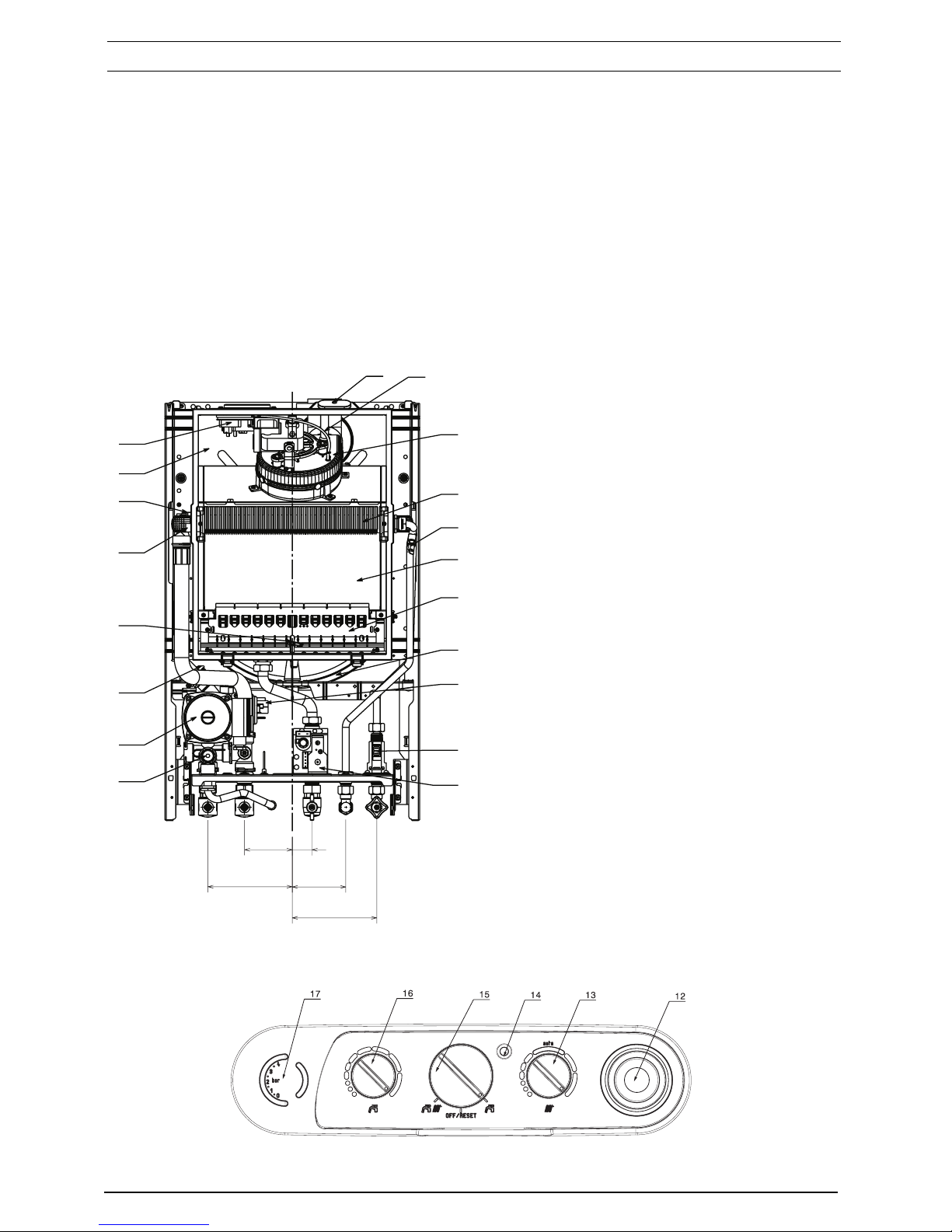
Fig.1 General Layout
1 Flue Analysis Test Point
2 Pressure Tube Negative
3 Fan Assembly
4 Heat Exchanger
5 Secondary thermistor
6 Combustion chamber
7 Burner
8 Expansion vessel
9 Water pressure switch
10 Domestic Hot Water Flow Switch
11 Gas Valve
12 Timeclock
13 CH position
14 Fault indicator led
15 Mode selector switch
16 DHW position
17 Pressure gauge
18 Safety valve
19 Pump
20 Auto air vent
21 Electrode
22 High limit thermistor
23 Primary thermistor
24 Air chamber (with cover removed)
25 Air pressure switch
26 Auto by pass (fig. 2)
27 Water flow restrictor (fig. 2)
The Vokera Compact range of appliances are combined
central heating and domestic hot water boilers, which –
by design – incorporates full sequence electronic ignition,
circulating pump, expansion vessel, safety valve,
pressure gauge, automatic by-pass, and mechanical time
clock.
Compact is produced as a room sealed appliance, suitable
for wall mounting applications only. Compact is provided
with a fan powered flue outlet with an annular co-axial
combustion air intake that can be rotated – horizontally –
through 360 degrees for various horizontal or vertical
applications, and can also be converted for use with a
rear flue outlet. Compact can also be used with the
Vokera twin flue system.
This appliance is designed primarily for use with sealed
systems; consequently it is not intended for use on an
open vented system.
Fig. 1
35
150
95
1
2
3
4
5
6
7
8
9
10
11
18
19
20
21
22
23
24
25
85
150
2
Compact
SECTION 1 DESIGN PRINCIPLES AND OPERATING SEQUENCE
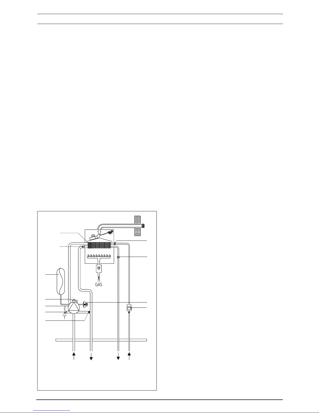
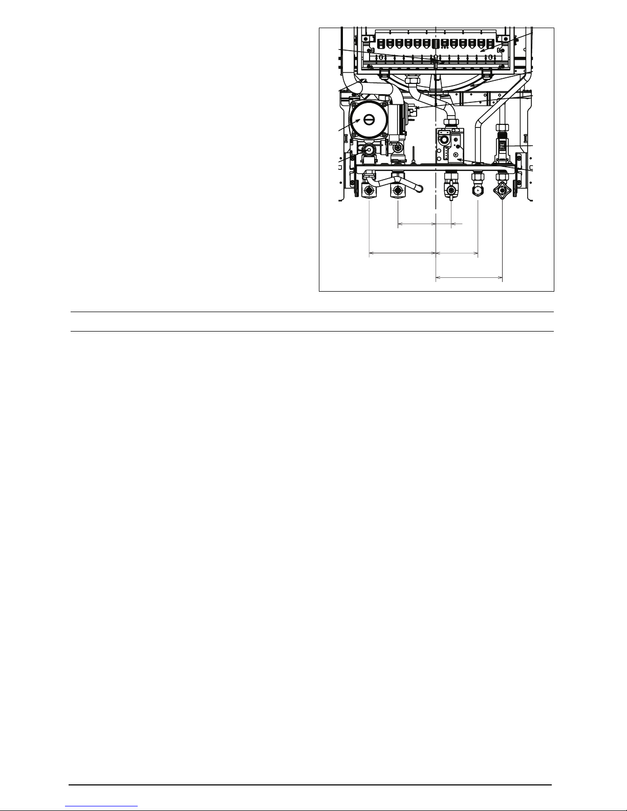
Fig. 2
1.1 PRINCIPLE COMPONENTS
● A fully integrated, electronic control board fea-
turing mode selection switch, full sequenceelectronic ignition, temperature control system,
and appliance status indicator.
● A BI-thermal gas to water heat exchanger.
● A multi-functional gas valve.
● Two-stage, primary water pressure switch.
Integral pump, expansion vessel, pressure relief valve, pressure gauge, domestic water flow
switch, fan, differential air pressure switch, and
time clock.
MODES OF OPERATION
1.2 CENTRAL HEATING MODE
When there is a request for central heating via the
time-clock and/or any external controls, the pump
and fan are started, the fan proves the differential
air pressure switch which in-turn, allows an ignition
sequence to begin.
Ignition is sensed by the electronic circuitry to
ensure flame stability at the burner. Once successful ignition has been achieved the appliance
operates al 75% of maximum for a fifteen-minute
period, and thereafter the appliance operates on
maximum output until the desired temperature
setting is reached.
Once the desired temperature is reached, the
burner will modulate to maintain that temperature, however should the temperature within the
appliance continue to rise, the burner will shut
down and the boiler will perform a three-minute
anti-cycle (timer delay).
1.3 HOT WATER MODE
When there is a demand for domestic hot water
the domestic hot water flow switch is proved by
the flow of water through the appliance, this
allows the fan to run, the fan proves the differential air pressure switch which in-turn, allows an
ignition sequence to begin.
Ignition is sensed by the electronic circuitry to
ensure flame stability at the burner. Once
successful ignition has been achieved the appliance will modulate burner gas pressure to maintain the desired water temperature, should the
temperature of the domestic hot water exceed
the temperature setting by 5 ºC the burner will
shut down until the water temperature drops
below the required setting.
1.4 SAFETY DEVICES
In both central heating and domestic hot water
modes, safe operation is ensured by.
● A water pressure switch that monitors the sys-
tem pressure and will deactivate the pump and
prevent burner ignition should the pressure or
primary flow rate fall below the rated tolerance.
● Differential air pressure switch that checks the
correct operation of the fan and flue thereby
preventing or interrupting burner operation.
● A high limit thermostat that overrides the con-
trol circuit to prevent or interrupt burner ignition.
● A safety valve which releases excess pressure
from the primary circuit.
1.5 FROST PROTECTION
The appliance has built-in frost protection that
allows the pump to operate if the appliance temperature drops to 7 ºC, should the temperature
continue to drop the burner will light until the
primary circuit temperature exceeds 30 ºC.
return flow
hw
outlet
cold
inlet
27
5
9
10
26
19
8
23
4
20
18
3
Compact
SECTION 2 TECHNICAL DATA
Ref. Condition 15 °C , 1013,25 mbar, dry gas
NOTE: L.P.G. data refer to section 10
Compact 24 Compact 28
2.1 Central heating
Heat input (kW) 26.3 31.0
Heat output (maximum) kW 24.0 28.0
Heat output (minimum) kW 9.4 10.5
Minimum working pressure 0,5 bar 0,5 bar
Maximum working pressure 3.0 bar 3.0 bar
Minimum flow rate 350 l/h 350 l/h
2.2 Domestic hot water
Heat input (kW) 26.3 31.0
Heat output (maximum) kW 24.0 28.0
Heat output (minimum) kW 8.2 8.7
Flow rate (35 °C rise) 9.8 l/min 11.5 l/min
Maximum inlet pressure 6.0 bar 6.0 bar
Minimum inlet working pressure 0.15 bar 0.15 bar
Minimum flow rate 2 l/min. 2 l/min.
2.3 Gas pressures
Inlet pressure G20 20.0 mbar 20.0 mbar
Maximum burner pressure 10.1 mbar 10.2 mbar
Minimum burner pressure (central heating) 1.9 mbar 1.9 mbar
Minimum burner pressure (domestic hot water) 1.5 mbar 1.3 mbar
Gross rate (maximum) 2.78 m3/h 3.28 m3/h
Injectors size 12 x 1.35 mm 14 x 1.35 mm
2.4 Expansion vessel
Capacity 8 litres 8 litres
Maximum system volume 76 litres 76 litres
Pre-charge pressure 1.0 bar 1.0 bar
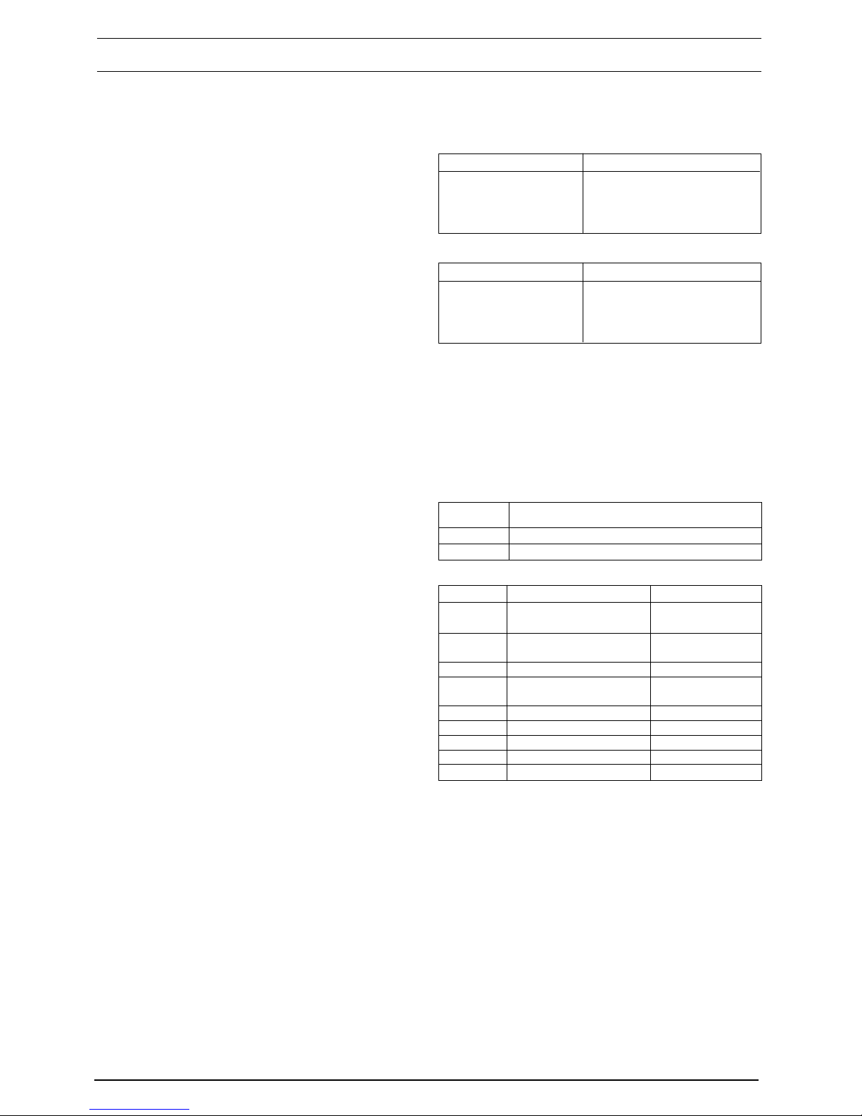
2.5 Dimensions
Height 740 mm 740 mm
Width 400 mm 450 mm
Depth 328 mm 328 mm
Dry weight 34 kg 37 kg
2.6 Clearances
Left side 50 mm 50 mm
Right side 12 mm 12 mm
Top 150 mm from casing or 25 mm above flue elbow, whichever is applicable
Bottom 150 mm 150 mm
Front 600 mm 600 mm
2.7 Connections
Flow & return 22 mm 22 mm
Hot & cold water connections 15 mm 15 mm
Gas 15 mm 15 mm
Safety valve 15 mm 15 mm
2.8 Electrical
Voltage 230V/~ 50hz 230V/~ 50hz
Power consumption 125 W 125 W
Internal fuse 2 A 2 A
PCB fuse 2 AF 2 AF
External fuse 3 A 3 A
2.9 Flue details
Maximum horizontal flue length (concentric) 4.25 m 3.4 m
Maximum vertical flue length (concentric) 5 m 4.2 m
Maximum twin flue length (horizontal or vertical) 14 m + 14 m 14 m + 14 m
Maximum rear flue length (see section 11) 1.0 m 1.0 m
2.10 Efficiency
SEDBUK Band “D” Band “D”
4
Compact
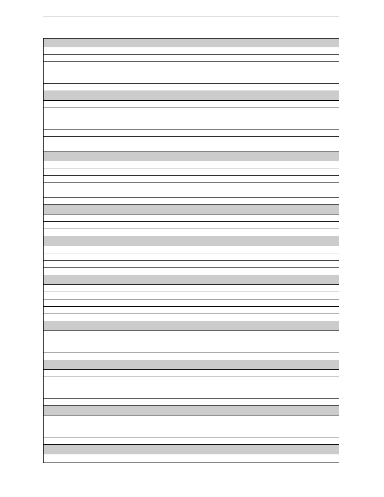
2.11 PUMP DUTY
Fig. 3 shows the flow rate available – after
allowing for pressure loss through the
appliance – against system pressure loss.
When using this graph apply only the
pressure loss of the system. The graph is
based on a 20 ºC temperature differential.
Fig. 3
Fig. 4
Water pressure (mbar)
Litres Per Hour (x100)
100
200
300
400
500
600
0 100 200 300 400 500 600 700 800 900 1000 1100 1200 1300 1400
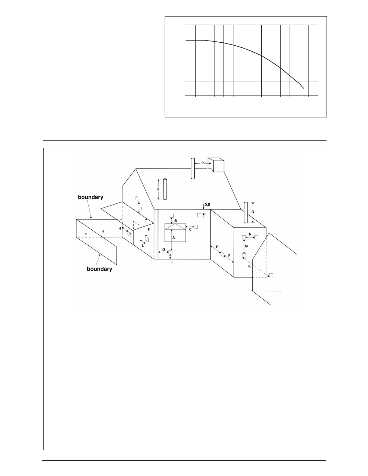
SECTION 3 GENERAL REQUIREMENTS (UK)
Key Location Minimum distance
A Below an opening (window, air-brik, etc.) 300 mm
B Above an opening (window, air-brik, etc.) 300 mm
C To the side of an opening (window, air-brik, etc.) 300 mm
D Below gutter, drain-pipe, etc. 75 mm
E Below eaves 200 mm
F Below balcony, car-port roof, etc. 200 mm
G To the side of a soil/drain-pipe, etc. 150 mm
H From internal/external corner or boundary 300 mm
I Above ground, roof, or balcony level 300 mm
J From a surface or boundary facing the terminal 600 mm
K From a terminal facing a terminal 1200 mm
L From an opening in the car-port into the building 1200 mm
M Vertically from a terminal on the same wall 1500 mm
N Horizontally from a terminal on the same wall 300 mm
P From a structure to the side of the vertical terminal 300 mm
Q From the top of the vertical terminal to the roof flashing As determined by the fixed collar
of the vertical terminal
.

5
Compact
This appliance must be installed by a competent
person in accordance with the Gas Safety
(Installation & Use) Regulations.
3.1 RELATED DOCUMENTS
The installation of this boiler must be in accordance
with the relevant requirements of the Gas Safety
(Installation & Use) Regulations, the local building
regulations, the current I.E.E. wiring regulations,
the bylaws of the local water undertaking, the
Building Standards (Scotland) Regulation, and
Building Standards (Northern Ireland)
Regulations.
It should be in accordance also with any relevant
requirements of the local authority and the relevant
recommendations of the following British Standard
Codes of Practice.
3.2 LOCATION OF APPLIANCE
The appliance may be installed in any room or
internal space, although particular attention is
drawn to the requirements of the current I.E.E.
wiring regulations, and in Scotland, the electrical
provisions of the Building Regulations, with
respect to the installation of the appliance in a
room or internal space containing a bath or shower.
When an appliance is installed in a room or
internal space containing a bath or shower, the
appliance or any control pertaining to it must not
be within reach of a person using the bath or
shower.
The location chosen for the appliance must permit
the provision of a safe and satisfactory flue and
termination. The location must also permit an
adequate air supply for combustion purposes
and an adequate space for servicing and air
circulation around the appliance. Where the
installation of the appliance will be in an unusual
location special procedures may be necessary,
BS 6798 gives detailed guidance on this aspect.
A compartment used to enclose the appliance
must be designed and constructed specifically
for this purpose. An existing compartment/
cupboard may be utilised provided that it is
modified to suit.
Details of essential features of compartment/
cupboard design including airing cupboard
installations are given in BS 6798. This appliance
is not suitable for external installation.
3.3 GAS SUPPLY
The gas meter – as supplied by the gas supplier
– must be checked to ensure that it is of adequate
size to deal with the maximum rated input of all
the appliances that it serves. Installation pipes
must be fitted in accordance with BS 6891.
Pipe work from the meter to the appliance must
be of adequate size. Pipes of a smaller size than
the appliance gas inlet connection must not be
used. The installation must be tested for
soundness in accordance with BS6891.
If the gas supply serves more than one appliance,
it must be ensured that an adequate supply is
maintained to each appliance when they are in
use at the same time.
3.4 FLUE SYSTEM
The terminal should be located where the dispersal
of combustion products is not impeded and with
due regard for the damage and discoloration that
may occur to building products located nearby.
The terminal must not be located in a place where
it is likely to cause a nuisance (fig. 4).
In cold and/or humid weather, water vapour may
condense on leaving the terminal; the effect of
such pluming must be considered.
BS 5440 PART 1 FLUES
BS 5440 PART 2 FLUES AND VENTILATION
BS 5449 PART 1 FORCED CIRCULATION HOT WATER SYSTEMS
BS5546 INSTALLATION OF GAS HOT WATER SUPPLIES FOR DOMESTIC PURPOSES
(2ND FAMILY GASES)
BS 6798 BOILERS OF RATED INPUT NOT EXCEEDING 60kW
BS 6891 LOW PRESSURE INSTALLATION PIPES
BS 7074 PART 1 APPLICATION, SELECTION, AND INSTALLATION OF EXPANSION VESSELS AND
ANCILLARY EQUIPMENT FOR SEALED WATER SYSTEMS
If installed less than 2 m above a pavement or
platform to which people have access (including
balconies or flat roofs) the terminal must be
protected by a guard of durable material. The
guard must be fitted centrally over the terminal.
Refer to BS 5440 Part 1, when the terminal is 0.5
metres (or less) below plastic guttering or 1 metre
(or less) below painted eaves.
3.5 AIR SUPPLY
The following notes are intended for general
guidance only.
This appliance is a room-sealed, fan-flued boiler,
consequently it does not require a permanent air
vent for combustion air supply.
When installed in a cupboard or compartment,
ventilation for cooling purposes is also not
required.
3.6 WATER CIRCULATION
Detailed recommendations are given in BS 5449
Part 1 and BS 6798. The following notes are for
general guidance only.
6
Compact
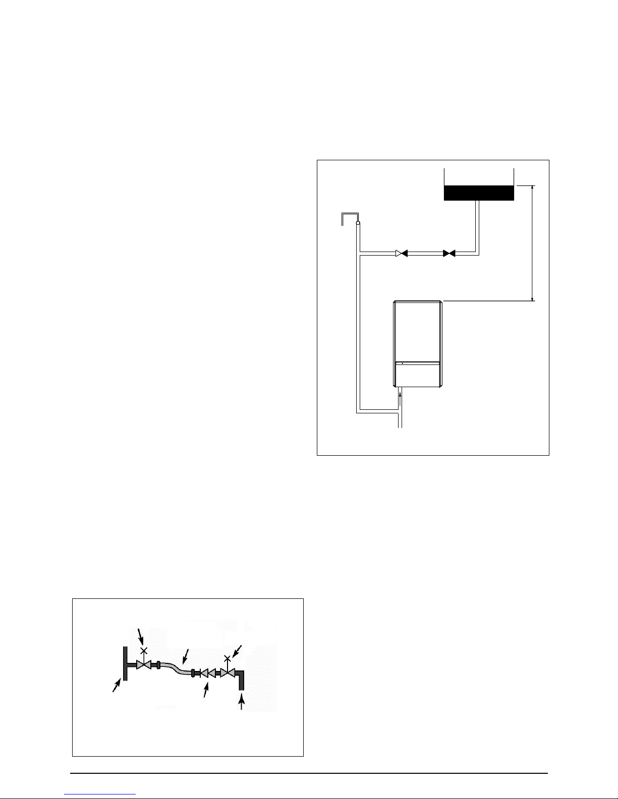
Fig. 5a
3.6.7 LOW PRESSURE SEALED SYSTEM
An alternative method of filling the system would
be from an independent make-up vessel or tank
mounted in a position at least 1 metre above the
highest point in the system and at least 5 metres
above the boiler (fig. 5a).
The cold feed from the make-up vessel or tank
must be fitted with an approved non-return valve
and stopcock for isolation purposes. The feed
pipe should be connected to the return pipe as
close to the boiler as possible.
3.6.8 FREQUENT FILLING
Frequent filling or venting of the system may be
indicative of a leak. Care should be taken during
the installation of the appliance to ensure all
aspects of the system are capable of withstanding
pressures up to at least 3 bar.
3.7 ELECTRICAL SUPPLY
The appliance is supplied for operation on 230V
@ 50Hz electrical supply; it must be protected
with a 3-amp fuse. The method of connection to
the mains electricity supply must allow for
complete isolation from the supply. The preferred
method is by using a double-pole switch with a
contact separation of at least 3 mm. The switch
must only supply the appliance and its
corresponding controls, i.e. time clock, room
thermostat, etc. Alternatively an un-switched
shuttered socket with a fused 3-pin plug both
complying with BS 1363 is acceptable.
3.8 SHOWERS
If the appliance is intended for use with a shower,
the shower must be thermostatically controlled
and be suitable for use with a combination boiler.
3.6.1 PIPEWORK
It is recommended that copper tubing to BS 2871
Part 1 is used in conjunction with soldered capillary
joints.
Where possible pipes should have a gradient to
ensure air is carried naturally to air release points
and that water flows naturally to drain cocks.
Except where providing useful heat, pipes should
be insulated to avoid heat loss and in particular to
avoid the possibility of freezing. Particular attention
should be paid to pipes passing through ventilated
areas such as under floors, loft space, and void
areas.
3.6.2 AUTOMATIC BY-PASS
The appliance has a built-in automatic by-pass,
consequently there is no requirement for an
external by-pass, however the design of the
system should be such that it prevents boiler
‘cycling’.
3.6.3 DRAIN COCKS
These must be located in accessible positions to
facilitate draining of the appliance and all water
pipes connected to the appliance. The drain
cocks must be manufactured in accordance with
BS 2879.
3.6.4 AIR RELEASE POINTS
These must be positioned at the highest points in
the system where air is likely to be trapped. They
should be used to expel trapped air and allow
complete filling of the system.
3.6.5 EXPANSION VESSEL
The appliance has an integral expansion vessel
to accommodate the increased volume of water
when the system is heated. It can accept up to 8
litres of expansion from within the system,
generally this is sufficient, however if the system
has an unusually high water content, it may be
necessary to provide additional expansion
capacity (see section 6.19).
3.6.6 FILLING POINT
A method for initial filling of the system and
replacing water lost during servicing etc. must be
provided. This method of filling must comply with
the current Water Supply (Water Fittings)
Regulations 1999 and Water Bylaws 2000
(Scotland). Fig. 5 shows an accepted method.
Fig. 5
control valve
temporary
connection
control valve
supply pipe
double check
valve
flow/return
pipe
Make-up vessel
or tank
Automatic
air-vent
Non-return
valve
Stopcock
5.0 metres minimum
Heating
return
7
Compact
Fig. 6
3.9 MOUNTING ON A COMBUSTIBLE SURFACE
If the appliance is to be fitted on a wall of
combustible material, a sheet of fireproof material
must protect the wall.
3.10 TIMBER FRAMED BUILDING
If the appliance is to be fitted in a timber framed
building, it should be fitted in accordance with the
Institute of Gas Engineers publication (IGE/UP/
7) ‘Guide for Gas Installations in Timber Frame
Buildings’.
3.11 INHIBITORS
Vokera recommend that a neutral inhibitor is
used to protect the heating system from the
effects of corrosion and/or electrolytic action.
The inhibitor must be administered in strict
accordance with the manufacturers* instructions.
*Fernox and Sentinel manufacture products that
have proved suitable for use with Vokera
appliances. Vokera Ltd. cannot comment on the
suitability of any other such product with our
appliances.
SECTION 3A GENERAL REQUIREMENTS (EIRE)
This appliance must be installed by a competent
person in accordance with and defined by, the
Standard Specification (Domestic Gas
Installations) Declaration (I.S. 813).
3A.1 RELATED DOCUMENTS
The installation of this boiler must be in accordance
with the relevant requirements of the local building
regulations, the current ETCI National Rules for
Electrical Installations, and the bylaws of the
local water undertaking.
It should be in accordance also with any relevant
requirements of the local and/or district authority.
3A.2 LOCATION OF APPLIANCE
The appliance may be installed in any room or
internal space, although particular attention is
drawn to the requirements of the current ETCI
National Rules for Electrical Installations, and
I.S. 813, Annex K.
When an appliance is installed in a room or internal
space containing a bath or shower, the appliance
or any control pertaining to it must not be within
reach of a person using the bath or shower.
The location chosen for the appliance must permit
the provision of a safe and satisfactory flue and
termination. The location must also permit an
adequate air supply for combustion purposes
and an adequate space for servicing and air
circulation around the appliance. Where the
installation of the appliance will be in an unusual
location special procedures may be necessary,
refer to I.S. 813 for detailed guidance on this
aspect. A compartment used to enclose the
appliance must be designed and constructed
specifically for this purpose. An existing
compartment/cupboard may be utilised provided
that it is modified to suit.
This appliance is not suitable for external
installation.
3A.3 GAS SUPPLY
The gas meter – as supplied by the gas supplier
– must be checked to ensure that it is of adequate
size to deal with the maximum rated input of all
the appliances that it serves. Installation pipes
must be fitted in accordance with I.S. 813.
Pipe work from the meter to the appliance must
be of adequate size. Pipes of a smaller size than
the appliance gas inlet connection must not be
used. The installation must be tested for
soundness in accordance with I.S. 813.
If the gas supply serves more than one appliance,
it must be ensured that an adequate supply is
maintained to each appliance when they are in
use at the same time.
3A.4 FLUE SYSTEM
The terminal should be located where the dispersal
of combustion products is not impeded and with
due regard for the damage and discoloration that
may occur to building products located nearby.
The terminal must not be located in a place where
it is likely to cause a nuisance (see I.S. 813).
In cold and/or humid weather, water vapour may
condense on leaving the terminal; the effect of
such pluming must be considered.
If installed less than 2 m above a pavement or
platform to which people have access (including
balconies or flat roofs) the terminal must be
protected by a guard of durable material. The
guard must be fitted centrally over the terminal.
Refer to I.S. 813, when the terminal is 0.5 metres
(or less) below plastic guttering or 1 metre (or
less) below painted eaves.
35
150
95
85
150

8
Compact
3A.5 AIR SUPPLY
The following notes are intended for general
guidance only. This appliance is a room-sealed,
fan-flued boiler, consequently it does not require
a permanent air vent for combustion air supply.
When installed in a cupboard or compartment,
ventilation for cooling purposes is also not
required.
3A.6 WATER CIRCULATION
Specific recommendations are given in I.S. 813.
The following notes are for general guidance
only.
3A.6.1 PIPEWORK
It is recommended that copper tubing be used in
conjunction with soldered capillary joints.
Where possible pipes should have a gradient to
ensure air is carried naturally to air release points
and that water flows naturally to drain cocks.
Except where providing useful heat, pipes should
be insulated to avoid heat loss and in particular to
avoid the possibility of freezing. Particular attention
should be paid to pipes passing through ventilated
areas such as under floors, loft space, and void
areas.
3A.6.2 AUTOMATIC BY-PASS
The appliance has a built-in automatic by-pass,
consequently there is no requirement for an
external by-pass, however the design of the
system should be such that it prevents boiler
‘cycling’.
3A.6.3 DRAIN COCKS
These must be located in accessible positions to
facilitate draining of the appliance and all water
pipes connected to the appliance.
3A.6.4 AIR RELEASE POINTS
These must be positioned at the highest points in
the system where air is likely to be trapped. They
should be used to expel trapped air and allow
complete filling of the system.
3A.6.5 EXPANSION VESSEL
The appliance has an integral expansion vessel
to accommodate the increased volume of water
when the system is heated. It can accept up to 8
litres of expansion from within the system,
generally this is sufficient, however if the system
has an unusually high water content, it may be
necessary to provide additional expansion
capacity (see section 6.19).
3A.6.6 FILLING POINT
A method for initial filling of the system and
replacing water lost during servicing etc. has
been provided. You should ensure this method of
filling complies with the local water authority
regulations.
3A.6.7 LOW PRESSURE SEALED SYSTEM
An alternative method of filling the system would
be from an independent make-up vessel or tank
mounted in a position at least 1 metre above the
highest point in the system and at least 5 metres
above the boiler (fig. 5).
The cold feed from the make-up vessel or tank
must be fitted with an approved non-return valve
and stopcock for isolation purposes. The feed
pipe should be connected to the return pipe as
close to the boiler as possible.
3A.6.8 FREQUENT FILLING
Frequent filling or venting of the system may be
indicative of a leak. Care should be taken during
the installation of the appliance to ensure all
aspects of the system are capable of withstanding
pressures up to at least 3 bar.
3A.7 ELECTRICAL SUPPLY
The appliance is supplied for operation on 230V
@ 50Hz electrical supply; it must be protected
with a 3-amp fuse. The method of connection to
the mains electricity supply must allow for
complete isolation from the supply. The preferred
method is by using a double-pole switch with a
contact separation of at least 3 mm. The switch
must only supply the appliance and its
corresponding controls, i.e. time clock, room
thermostat, etc.
3A.8 SHOWERS
If the appliance is intended for use with a shower,
the shower must be thermostatically controlled
and be suitable for use with a combination boiler.
3A.9 MOUNTING ON A COMBUSTIBLE SURFACE
If the appliance is to be fitted on a wall of
combustible material, a sheet of fireproof material
must protect the wall.
3A.10 TIMBER FRAMED BUILDINGS
If the appliance is to be fitted in a timber framed
building, it should be fitted in accordance with I.S.
813 and local Building Regulations.
The Institute of Gas Engineers publication (IGE/
UP/7) ‘Guide for Gas Installations in Timber Frame
Buildings’ gives specific advice on this type of
installation.
3A.11 INHIBITORS
Vokera recommend that a neutral inhibitor is
used to protect the heating system from the
effects of corrosion and/or electrolytic action.The
inhibitor must be administered in strict accordance
with the manufacturers* instructions.
*Fernox and Sentinel manufacture products that
have proved suitable for use with Vokera
appliances. Vokera Ltd. cannot comment on the
suitability of any other such product with our
appliances.
3A.12 DECLARATION OF CONFORMITY
A Declaration of Conformity (as defined in I.S.
813) must be provided on completion of the
installation.
A copy of the declaration must be given to the
responsible person and also to the gas supplier if
required.
9
Compact
SECTION 4 INSTALLATION
4.1 DELIVERY
The appliance is delivered in a heavy-duty cardboard carton. Lay the carton on the floor with the
writing the correct way up.
4.2 CONTENTS
Contained within the carton is:
● the boiler
● the wall mounting bracket
● an accessories pack containing service valves
and sealing washers
● the instructions pack containing installation &
servicing instructions, appliance logbook, user
instructions, guarantee registration card, 3 amp
fuse and flue restrictor ring.
4.3 UNPACKING
At the top of the carton pull both sides open – do
not use a knife – unfold the rest of the carton from
around the appliance, carefully remove all
protective packaging from the appliance, and lay
the accessories etc. to one side. Protective gloves
should be used to lift the appliance, the appliance
back-frame should be used for lifting points.
4.4 PREPARATION FOR MOUNTING THE
APPLIANCE
The appliance should be mounted on a smooth,
non-combustible, vertical surface, which must be
capable of supporting the full weight of the
appliance. Care should be exercised when
determining the position of the appliance with
respect to hidden obstructions such as pipes,
cables, etc.
When the position of the appliance has been
decided – using the template supplied – carefully
mark the position of the wall bracket (fig. 7) and
flue-hole (if applicable).
4.4.1 IMPORTANT
There are three hole types set out on the
appliance template:
● type 1 should be used in conjunction with
the telescopic flue kits (part no. 0225705 &
0225710)
● type 2 should be used in conjunction with
standard horizontal flue kit (part no.
2359029)
● type 3 should be used in conjunction with
the telescopic rear flue kits (part no.
0225905 & 0225910).
4.4.2 FLUE RESTRICTOR RING
To ensure maximum efficiency of the appliance,
it may be necessary to fit one of the supplied flue
restrictor rings to the appliance flue outlet.
4.5 FITTING THE FLUE
The top flue outlet permits both horizontal and
vertical flue applications to be considered,
alternatively, the Vokera twin flue system can be
utilised if longer flue runs are required.
4.5.1 CONCENTRIC HORIZONTAL FLUE
(For concentric vertical flue, see section 4.5.2).
(For twin flue applications, see section 4.5.3).
The appliance flue outlet elbow can be rotated
through 360º on its vertical axis. In addition the
flue may be extended from the outlet elbow in the
horizontal plane (see section 4.4.2), however if
the flue is to be extended or additional bends are
to be fitted, the standard horizontal flue kit (part
no. 2359029) must be used. A reduction must
also be made to the maximum length (see table)
when additional bends are used.
Bend Reduction in maximum flue length for each bend
45º bend 0.5 metre
90º bend 0.85 metre
Using the template provided (see section 4.4.1),
mark and drill a 125 mm hole for the passage of
the flue pipe. The hole should have a 1º drop
from the boiler to outside, to eliminate the
possibility of rainwater entering the appliance via
the flue.
The fixing holes for the wall-mounting bracket
should now be drilled and plugged, an appropriate
type and quantity of fixing should be used to
ensure that the bracket is mounted securely.
Once the bracket has been secured to the wall,
mount the appliance onto the bracket.
Horizontal flue terminals and accessories
Part No. Description Min-Max Length
0225705 Standard telescopic flue 380 mm – 600 mm
(Dimension ‘X’)
0225710 Extended telescopic flue 600 mm – 920 mm
(Dimension ‘X’)
2359029 Horizontal flue kit
For use with add. Bends 833 mm
& extensions (dimension ‘X’)
2359069 750 mm extension 750 mm
2359079 1500 mm extension 1500 mm
2359049 45º bend (pair) N/A
2359059 90º bend N/A
0225760 Wall bracket (5) N/A
Total flue length Restrictor required
Less than 0.85 metre
Less than 2 metre
Less than 3 metre
Less than 4.25 metre
42 mm diameter
44 mm diameter
46 mm diameter
Not installed
Compact 24
Compact 28
Total flue length Restrictor required
Less than 0.85 metre
Less than 1.70 metre
Less than 2.70 metre
Less than 3.40 metre
45 mm diameter
47 mm diameter
49 mm diameter
Not installed
10
Compact
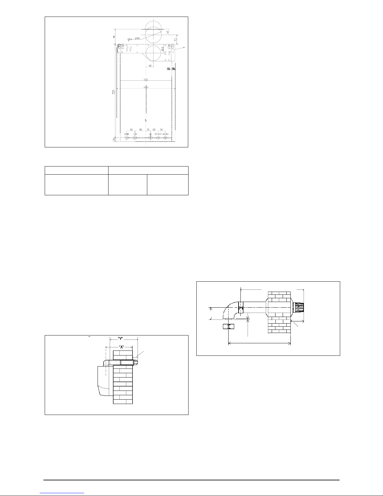
Carefully measure the distance from the centre of
the appliance flue outlet to the face of the outside
wall (dimension ‘X’, fig. 8). Add 50 mm to
dimension ‘X’ to give the overall flue length
(dimension ‘Y’). Using the complete telescopic
flue assembly adjust the length to suit dimension
‘Y’. Once the telescopic flue terminal has been
adjusted to the correct length, secure the flue
assembly with the screw supplied.
Insert the flue restrictor ring (supplied in the
instruction pack) into the appliance flue gas outlet.
Slide the flue assembly into the previously drilled
flue hole and locate the flue bend over the
appliance flue outlet. Push the flue bend down
over the appliance flue outlet and ensure the
correct seal is made. Pull the flue assembly
towards and over the flue bend – using a twisting
action – ensuring the correct seal is made. Check
that the terminal protrudes past the finished
outside wall by the correct length (115 mm).
NOTE
You must ensure that the entire flue system is
properly supported and connected. Seal the flue
assembly to the wall using cement or a suitable
alternative that will provide satisfactory
weatherproofing. The interior and exterior trim
can now be fitted.
FITTING THE STANDARD (2359029)
HORIZONTAL FLUE KIT (see section 4.4.1)
Carefully measure the distance from the centre
of the appliance flue outlet to the face of the
outside wall (dimension ‘X’, fig. 8A). Ensure the
inner (60 mm) pipe is fully inserted into the outer
(100 mm) pipe (when the inner pipe is fully
inserted, it stands proud of the outer pipe by 7.5
mm). Add 32 mm to dimension ‘X’ to give the
overall flue length (dimension ‘Y’). The standard
horizontal flue kit (part no. 2359029) is suitable
for a distance (dimension ‘Y’) of up to 865 mm.
NOTE
Dimension ‘Y’ is measured from the end of the
terminal to the end of the outer (100 mm) pipe.
The internal trim should be fitted to the flue pipe
before connection of the 90º bend.
Insert the flue restrictor ring (supplied with
instruction pack) into the appliance flue gas outlet
if the total flue length is less than 1.0 metre.
If the horizontal flue kit (2359029) requires to be
cut to the correct size (dimension ‘Y’), you must
ensure that the inner (60 mm) pipe stands proud
of the outer (100 mm) pipe by 7.5 mm (fig. 8B).
Ensure any burrs are filed or removed and that
any seals are located properly before assembly.
Connect the inner (60 mm) pipe of the terminal
assembly to the push-fit end of the 90º bend
(supplied) using a twisting action. Insert the
assembled flue into the previously drilled hole.
Using the clips & screws supplied, connect the
flue assembly to the boiler, ensuring that the
terminal protrudes past the finished outside wall
by the correct length (135 mm).
You must ensure that the entire flue system is
properly supported and connected.
Seal the flue assembly to the wall using cement
or a suitable alternative that will provide
satisfactory weatherproofing. The exterior trim
can now be fitted.
EXTENDING THE HORIZONTAL FLUE
If the horizontal flue requires extension/s or
additional bend/s, the standard horizontal flue
terminal (2359029) must be used. Connect the
bend – supplied with the terminal kit – to the top
of the boiler using the clips, screws & gaskets
supplied. The additional bends & extensions have
an internal push-fit connection, care should be
taken to ensure that the correct seal is made
when assembling the flue system. Connect the
required number of flue extensions or bends (up
to the maximum equivalent flue length) to the flue
terminal using the clips, screws & gaskets supplied
(fig. 8A & 8B).
type 1= centre of rear flue hole
using only 0225705 or
0225710 flue
type 2= centre of rear flue hole
for use with 2359029
type 3= for rear flue only
Fig. 8
“X” + 50 mm = “Y”
115 mm
Fig. 8A
Dimension “Y”
Dimension “X”
Max 833 mm
135 mm
7,5
110
Fig. 7
Total flue length Restrictor required
Less than 1 metre
Compact 24 Compact 28
40 mm diameter 42 mm diameter
FITTING THE TELESCOPIC FLUE KIT
(0225705 & 0225710)
3
2
1
11
Compact
Fig. 9
465 mm
300 mm
min.
150 mm
NOTE
When cutting the horizontal flue terminal or an
extension to the required length, you must ensure
that the excess is cut from the plain end of the
terminal or extension, and that the inner (60 mm)
pipe is 7.5 mm longer than outer (100 mm) pipe
(fig. 8A & 8B). Remove any burrs, and check that
any seals are located properly.
You must ensure that the entire flue system is
properly supported and connected.
Seal the flue assembly to the wall using cement
or a suitable alternative that will provide
satisfactory weatherproofing. The interior and
exterior trim can now be fitted.
4.5.2 CONCENTRIC VERTICAL FLUE
The vertical flue terminal can be connected directly
to the appliance flue outlet. Alternatively, an
extension or bend can be connected to the
appliance flue outlet if desired (see section 4.4.2),
however if additional bends are fitted, a reduction
must be made to the maximum flue length (see
table below).
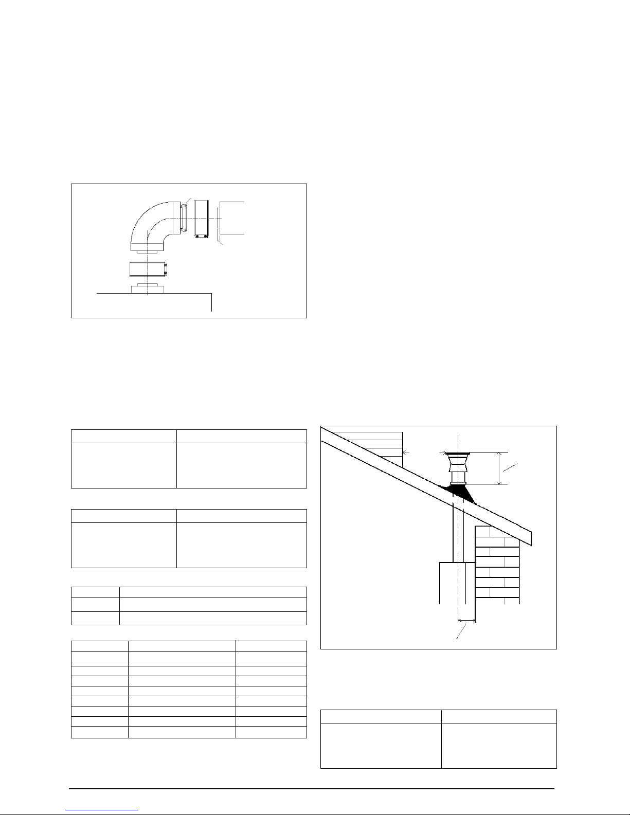
Using the dimensions given in fig. 9 as a reference,
mark and cut a 105 mm hole in the ceiling and/or roof.
Fig. 8B
Boiler
Push-fit connection
Extension
7,5 mm
Fit the appropriate flashing plate to the roof and
insert the vertical flue terminal through the flashing
plate from the outside, ensuring that the collar on
the flue terminal fits over the flashing.
The fixing holes for the wall-mounting bracket
should now be drilled and plugged, an appropriate
type and quantity of fixing should be used to
ensure that the bracket is mounted securely.
Once the bracket has been secured to the wall,
mount the appliance onto the bracket.
IMPORTANT
The vertical flue terminal is 1.0 metre in length
and cannot be cut; therefore it may be necessary
to adjust the height of the appliance to suit or use
a suitable extension.
Insert the flue restrictor ring into the appliance flue
outlet, in accordance with the table in section 4.4.2.
Connect the vertical flue assembly to the boiler
flue spigot using the 60 mm & 100 mm clips,
gaskets, & screws (supplied), ensuring the correct
seal is made. The flue support bracket (supplied
with the vertical flue kit) can now be fitted.
If the vertical flue requires extension/s or additional
bend/s, connect the required number of flue
extensions or bends (up to the maximum
equivalent flue length) between the boiler and
vertical flue assembly (fig. 8B).
NOTE
When cutting an extension to the required length,
you must ensure that the excess is cut from the
plain end of the extension and that the inner (60
mm) pipe is 7.5 mm longer than outer (100 mm)
pipe (fig. 8B). Remove any burrs, and check that
any seals are located properly.
You must ensure that the entire flue system is
properly supported and connected.
Total flue length Restrictor required
Less than 1.5 metre
Less than 2.5 metre
Less than 3.5 metre
Less than 5 metre
42 mm diameter
44 mm diameter
46 mm diameter
Not installed
Compact 24
Compact 28
Total flue length Restrictor required
Less than 1.5 metre
Less than 2.4 metre
Less than 3.4 metre
Less than 4.2 metre
45 mm diameter
47 mm diameter
49 mm diameter
Not installed
4.5.3 TWIN FLUE SYSTEM
Compact 24
Total flue length (air = fumes) Restrictor required
Less than 4.5 + 4.5
Less than 10.5 + 10.5
Less than 14 + 14
42 mm diameter
44 mm diameter
46 mm diameter
Bend Reduction in maximum flue length for each bend
45º bend 0.5 metre
90º bend 0.85 metre
Part No. Description Length
2359039 Vertical flue terminal 1.0 metre
0225770 Pitched roof flashing plate N/A
0225765 Flat roof flashing plate N/A
2359069 750 mm extension 750 mm
2359079 1500 mm extension 1500 mm
2359049 45º bend (pair) N/A
2359059 90º bend N/A
0225760 Wall bracket (5) N/A
Vertical flue terminal and accessories
12
Compact
4.5.3.2 INST ALLA TION OF CONDENSA TE DRAIN KIT
(fig. 10B)
The condensate drain kit must be fitted within 1 metre
of the appliance flue outlet. It is recommended that
the condensate drain kit should be fitted in the vertical
plane, however it can be fitted horizontally with care.
● Fit the first bend to the condensate drain kit or
exhaust connection manifold by firmly pushing
in to position.
● Using the two holes in the exhaust connection
manifold as a guide, drill a 3 mm hole in each
and secure using the screws provided.
● Connect the air inlet pipe to the air baffle as above.
● The twin flue pipes extensions and accessories
can now be installed by pushing together (the
plain end of each extension or bend should be
pushed approximately 50 mm into the female
socket of the previous piece).
The condensate drain trap must be connected
to the drain in accordance with building
Regulations or other rules in force.
Compact 28
Total flue length Restrictor required
Less than 4 + 4
Less than 8 + 8
Less than 12.5 + 12.5
Less than 14 + 14
45 mm diameter
47 mm diameter
49 mm diameter
Not required
The V ok era twin flue system enables greater flue
distances to be achieved (see section 2.8) than
that of the standard concentric flue system. It can
be used for horizontal or vertical applications,
however the twin flue system must be converted
to the dedicated concentric flue kit for termination.
It is essential that the installation of the twin flue
system be carried out in strict accordance with
these instructions.
GUIDANCE NOTES ON TWIN FLUE
INSTALLATION
● The flue must have a fall back of 1º back to the
appliance to allow any condensate that forms
in the flue system to drain. Consideration must
also be given to the fact that there is the
possibility of a small amount of condensate
dripping from the terminal.
● Ensure that the entire flue system is adequately
supported, use at least one bracket for each
extension.
● Extreme care must be taken to ensure that no
debris is allowed to enter the flue system at
any time.
● As the exhaust outlet pipe can reach very high
temperatures it must be protected to prevent
persons touching the hot surface.
Twin flue accessories
Part No. Description Length
0225805 Horizontal flue terminal 1.0 metre
0225810 Vertical flue terminal 1.0 metre
300 Twin adapter kit for Compact 24 N/A
2359249 Twin adapter kit for Compact 28 N/A
0225770 Pitched roof flashing plate N/A
0225765 Flat roof flashing plate N/A
0225815 Condensate drain kit N/A
0225820 0.25 m extension (pair) 250 mm
0225825 0.5 m extension (pair) 500 mm
0225830 1.0 m extension (pair) 1000 mm
0225835 2.0 m extension (pair) 2000 mm
0225840 45º bend (pair) N/A
0225845 90º bend (pair) N/A
0225850 Twin bracket (5) N/A
0225855 Single bracket (5) N/A
MOUNTING THE BOILER
The fixing holes for the wall-mounting bracket
should now be drilled and plugged, an
appropriate type and quantity of fixing should be
used to ensure that the bracket is mounted
securely. Once the bracket has been secured to
the wall, mount the appliance onto the bracket.
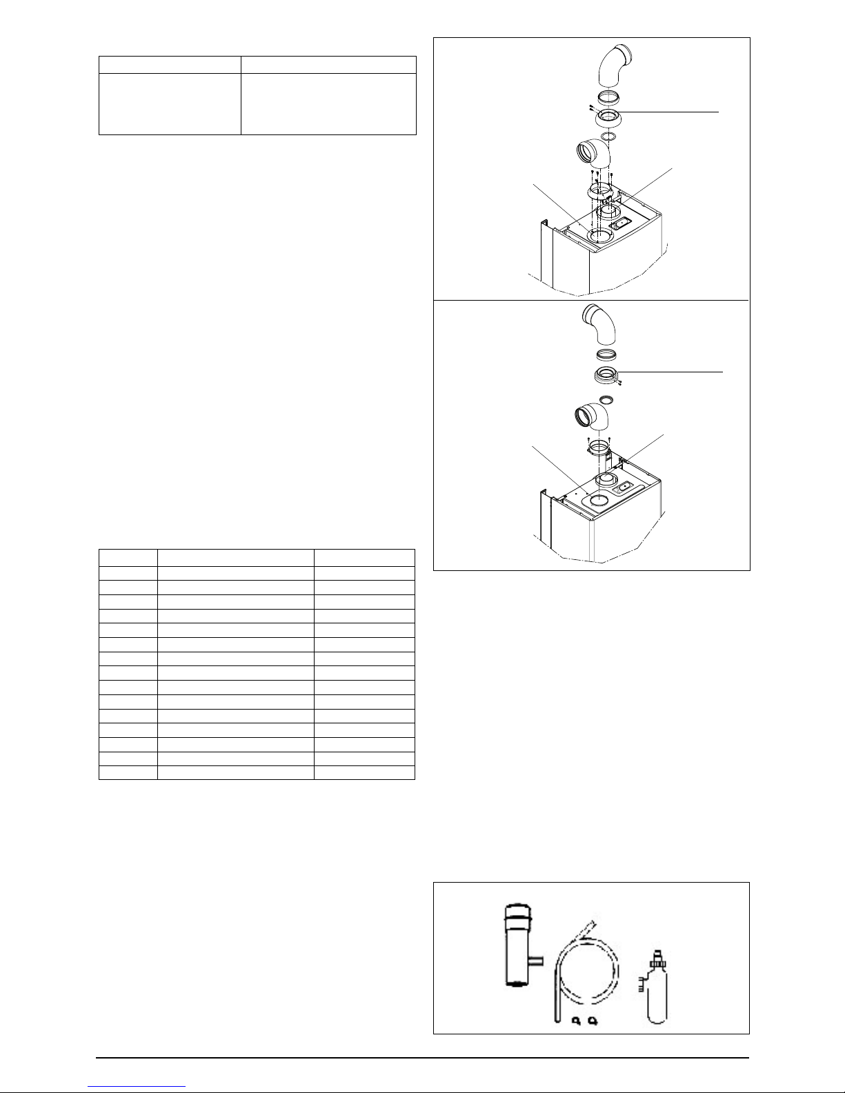
4.5.3.1 INSTALLATION OF TWIN ADAPTOR KIT (fig. 10 &
10A)
● Insert the exhaust connection manifold (B) onto
the appliance flue outlet and secure to the flue
spigot using the screws provided.
● Insert the silicone seal into the exhaust outlet.
● Remove the blanking plates (located to the left
of the appliance flue outlet) and – using the
same screws – install the air baffle (A).
Fig. 10
Fig. 10A
Condensate drain kit
restrictor ring
restrictor ring
flue outlet
flue outlet
air inlet
air inlet
Compact 24
Compact 28
Fig. 10B
 Loading...