

VOKERA Aria, Aria Series, Aria 6HP, Aria 8HP, Aria 11HP Installation & Servicing Instructions Manual
Page 1
Aria
Air to water heat pump
Installation
& Servicing
Instructions
THESE INSTRUCTIONS
TO BE RETAINED
BY USER
Vokèra is a licensed member of the Benchmark scheme
which aims to improve the standards of installation and
commissioning of domestic hot water systems in the UK.
Page 2

BUILDING REGULATIONS
This appliance must be installed and serviced
only by a competent person in accordance with
the current: IEE Regulations,
Building Regulation, Building Standards
(Scotland) (Consolidation), Building Regulations
(Northern Ireland), local water by-laws,
Health & Safety Document 63S (The Electricity at
Work Regulations 1989), IS 813 (Eire) and other
local requirements.
The relevant Standards should be followed,
including:
BS EN 15450: Heating systems in buildings –
Design of heat pump heating systems.
BS EN:12828 : Central heating for domestic
premises.
BS EN 7593 : Treatment of water in domestic hot
water central heating systems.
BS EN 14511 : Requirements heat pumps for
space heating and cooling.
BS EN 378 : Safety and environmental
requirements for heat pumps.
The Health and Safety at Work Act 1974.
The Management of Health and Safety at Work
Regulations 1999.
The Construction (Health, Safety and Welfare)
Regulations 1996.
The Construction (Design and Management)
Regulations 1994.
The Lifting Operations and Lifting Equipment
Regulations 1998.
Where no specific instruction is given, reference
should be made to the relevant codes of Practice.
There have been no banned substances
used in the manufacture of these
appliances.
________________________________________________________________
INDEX
1 GENERAL
.....................................................5
1.1 GENERAL PRECAUTIONS
....................................... 5
1.2 FUNDAMENTAL SAFETY RULES
............................ 5
1.3 DESCRIPTION OF THE APPLIANCE
....................... 6
1.4 IDENTIFICATION
...................................................... 7
1.5 TECHNICAL DATA
................................................... 8
1.6 HYDRAULIC DATA
.................................................. 9
1.7 ACCESSORIES
....................................................... 9
1.7.1 Electric heater
............................................... 9
1.8 HEAT PUMP COOLING CIRCUIT
........................... 10
1.9 ELECTRICAL PANEL AND WIRING
DIAGRAM ...... 10
1.9.1 ARIA 6HP / 8HP Models ............ 10
1.9.2 ARIA 11HP Model ........................... 12
2 INSTALLER
................................................ 13
2.1 CONTROL PANEL
................................................... 13
2.2 ACTIVATION & DEACTIVATION
............................. 15
2.2.1 Heating / Cooling activation
......................... 15
2.2.2 Heating / Cooling deactivation
..................... 16
2.3 OPERATIONS PERFORMED WITH
THE REMOTE ON-OFF “SO” and
SUMMER-WINTER “SEI” SWITCHES
..................................................... 17
2.3.1 Cooling function
............................................ 17
2.3.2 Heating function
............................................ 17
2.4 SHUTDOWN FOR LONG PERIODS
....................... 17
2.5 CLEANING
.............................................................. 17
2.6 MAINTENANCE
....................................................... 17
2.7 USEFUL INFORMATION
......................................... 18
2.8 RECEIVING THE PRODUCT
.................................. 18
2.9 DIMENSIONS WITH PACKAGING
.......................... 18
2.10 DIMENSIONS WITHOUT PACKAGING
.................. 19
Page 3

2.11 HANDLING AND TRANSPORT
............................... 19
2.12 POSITIONING
......................................................... 20
2.12.1 Fixing position of dampers
............................ 21
2.13 HYDRAULIC CONNECTIONS
................................ 22
2.14 POSITION OF THE FIXINGS
.................................. 24
2.15 ELECTRICAL CONNECTIONS
............................... 24
2.16 OUTSIDE CONNECTIONS AND
ELECTRICAL
POWER CABLE INFEED
........................................ 25
2.17 LOADING AND EMPTYING THE
SYSTEM ............ 27
2.17.2 Loading
......................................................... 27
2.17.2 Emptying
....................................................... 44
3 TECHNICAL SERVICE
............................... 28
3.1 RECOMMENDED OPERATING
CONDITIONS
.......................................................... 28
3.2 LIMIT OPERATING CONDITIONS
.......................... 28
3.3 PREPARATION FOR THE FIRST
STARTING UP
........................................................ 29
3.4 FIRST START-UP
.................................................... 29
3.6 ACTIVATION OF “SO” AND “SEI”
CONTROL ......... 30
3.6.1 Setting the “SO” remote control
.................... 30
1 GENERAL 1 GENERAL
3.6.2 Setting the “SEI” remote control
.................... 30
3.7 ANOMALY SIGNALS
............................................... 30
3.7.1 Manual anomaly reset
................................... 31
3.8 ACTIVATION and DEACTIVATION
OF THE UNIT
..........................................................31
3.9 OPERATIONS PERFORMED BY THE
ON-OFF “SO” AND SUMMER-WINTER
“SEI”
REMOTE SWITCHES
............................................. 33
3.10 DEFROSTING CHECK
............................................ 34
3.11 CONTROLS DURING AND AFTER
THE FIRST
START-UP
............................................................... 34
3.12 LONG TERM SHUTDOWN
..................................... 34
3.13 ROUTINE MAINTENANCE
..................................... 34
3.14 EXTRAORDINARY MAINTENANCE
....................... 34
3.14.1 Loading coolant gas
...................................... 34
3.14.2 Compressor
.................................................. 35
3.15 DISPLAY AND CONTROL
PARAMETERS ............. 35
3.15.1 Main parameters and variable
characteristics ...............................................
35
3.15.2 Access and modification of
parameters ........ 35
3.16 TROUBLESHOOTING
............................................. 36
Page 4
The following symbols are used in some parts of the booklet:
ATTENTION = for actions that require special precautions and an adequate preparation
FORBIDDEN = for actions that must NOT be carried out
1.1 GENERAL PRECAUTIONS
After removing the packing, check the
integrity and completeness of the contents. If
they do not correspond, contact the Vokera
agency that sold the unit.
Vokera appliances must be installed by
companies that are enabled in accordance with
legislations in force, and on completion of the
work, a declaration of conformity must be given
to the owner certifying that the installation has
been done correctly and in accordance with the
legislation in force and the indications given by
Vokera in the instruction booklet supplied with the
appliance.
These appliances have been built for
heating or climatisation of environments and
must be destined for this use, compatibly with
their performance characteristics.
These units contain R410A refrigerant
gas; take great care not to damage the gas circuit
and the finned battery. If the refrigerant gas
escapes, set the system master switch to
“OFF” and call immediately the Vokera technical
service, or other qualified personnel; do not
intervene personally on the unit.
If the equipment is not used for a long
period, the following operations should be carried
out:
- Turn the system master switch to “OFF”
- Close the water taps
- If there is the risk of freezing, make sure that
anti-freeze liquid has been added, otherwise
empty the system.
This instructions booklet is an integral part
of the unit and consequently must be kept with
care and must ALWAYS accompany the unit,
even when this is transferred to another owner or
user or transferred onto another system. If it gets
damaged or lost, request another copy from the
local Vokera technical service.
The manufacturer accepts no
responsibility, either contractual or extra
contractual, for damage to persons, animals or
property arising from incorrect installation or
adjustment, maintenance or improper use.
Should water leak from the unit, turn the
unit master switch to “OFF” and close the water
taps. Urgently call the Vokera service department
or professionally qualified personnel and under
no circumstances intervene personally on the
unit.
Repair or maintenance interventions must
only be carried out by the Vokera technical service
or personnel qualified according to the provisions
of this manual. Do not modify or tamper with the
unit as this could cause situations of danger and
the manufacturer shall not be responsible for any
damaged caused.
Page 5
1.2 FUNDAMENTAL SAFETY RULES
The use of products that use of electricity and
water requires the observation of some
fundamental safety rules such as:
Do not open the access flaps to the inner
parts of the unit without first having set the
system master switch to “OFF”.
Do not allow children to operate this unit.
Do not touch the unit if barefoot or with
parts of the body that are wet or humid.
Do not clean the unit without first
disconnecting it from the mains power supply by
switching the system master switch to “OFF”.
Do not modify or adjustment units without
authorisation and the indications of the
manufacturer.
Do not pull out or twist the electric cables
coming out of the unit, even when disconnected
from the mains power supply.
Do not introduce objects or substances
through the aspiration grills or the air outlets
Do not leave the packaging material
within the reach of children as it can be a source
of risk.
Before undertaking any maintenance
intervention on the unit, it is compulsory to cut
“OFF” the mains electrical supply by setting the
double pole master switch on the system to
“OFF”.
Do not spray or tip water directly onto the
unit.
Do not climb onto the unit or rest any
object on it.
Page 6
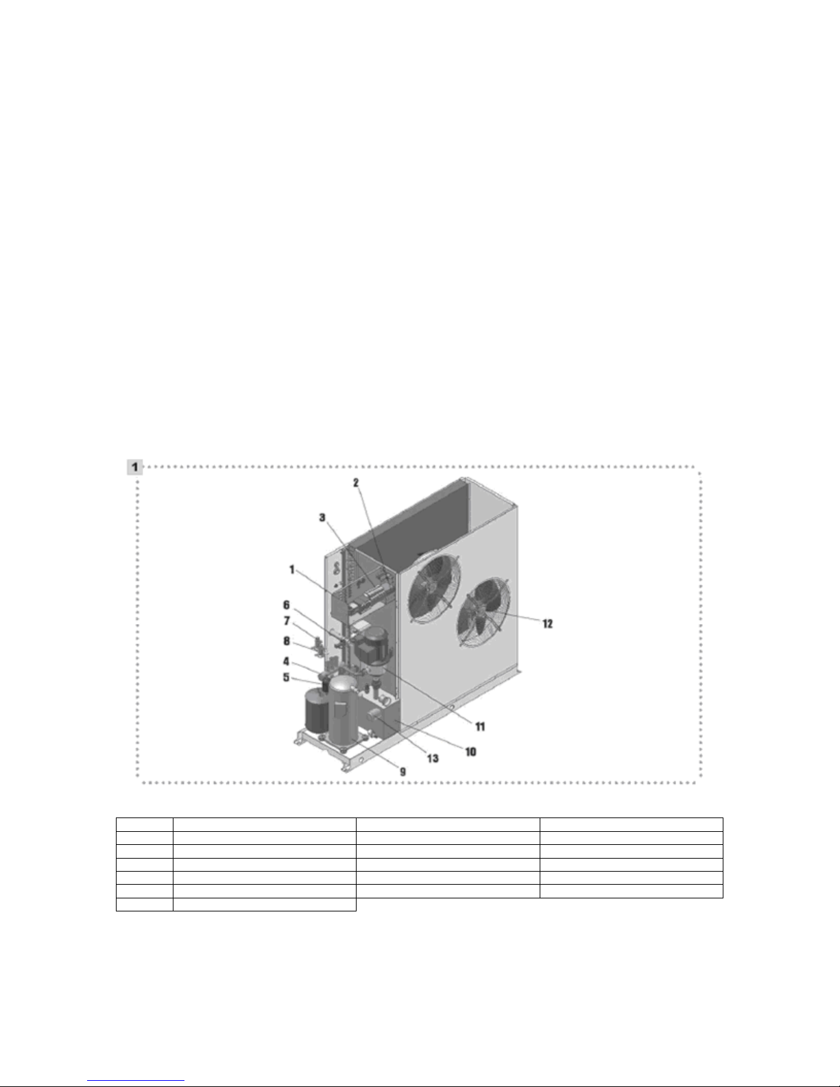
1.3 DESCRIPTION OF THE APPLIANCE
The Vokera ARIA heat pumps are available with
single phase power supplies, capable of
producing both hot water for heating and cold
water for cooling domestic, residential
environments and equipped with supplementary
electrical resistances which allow correct
functioning even in the most critical
environmental conditions They are best suited for
under floor heating or low temperature systems.
They use an internal Scroll type rotary
compressor mounted on anti-vibration supports
and located in a special compartment,
electronically controlled variable speed helical
fans that ensure silent high performance. The
user side plate exchanger in AISI 316 stainless
steel is insulated with an anti-condensation
coating and fitted with a flow regulator. The units
are fitted with various safety devices such as
pressure switches, flow gauge, sensors, specific
circuit breakers etc. An electronic device with
microprocessor control manages the operation.
The models are supplied with inertial storage built
into the unit.
Legend fig. 1
1 Electrical panel 8 Expansion valve (winter)
2 Control panel 9 Scroll compressor
3 Thermo magnetic switch 10 Hydraulic kit
4 4 way-valve 11 Pump
5 Dehydrator filter 12 Axial fan
6 Flow switch 13 Electric heater
7 Expansion valve (summer)
Page 7
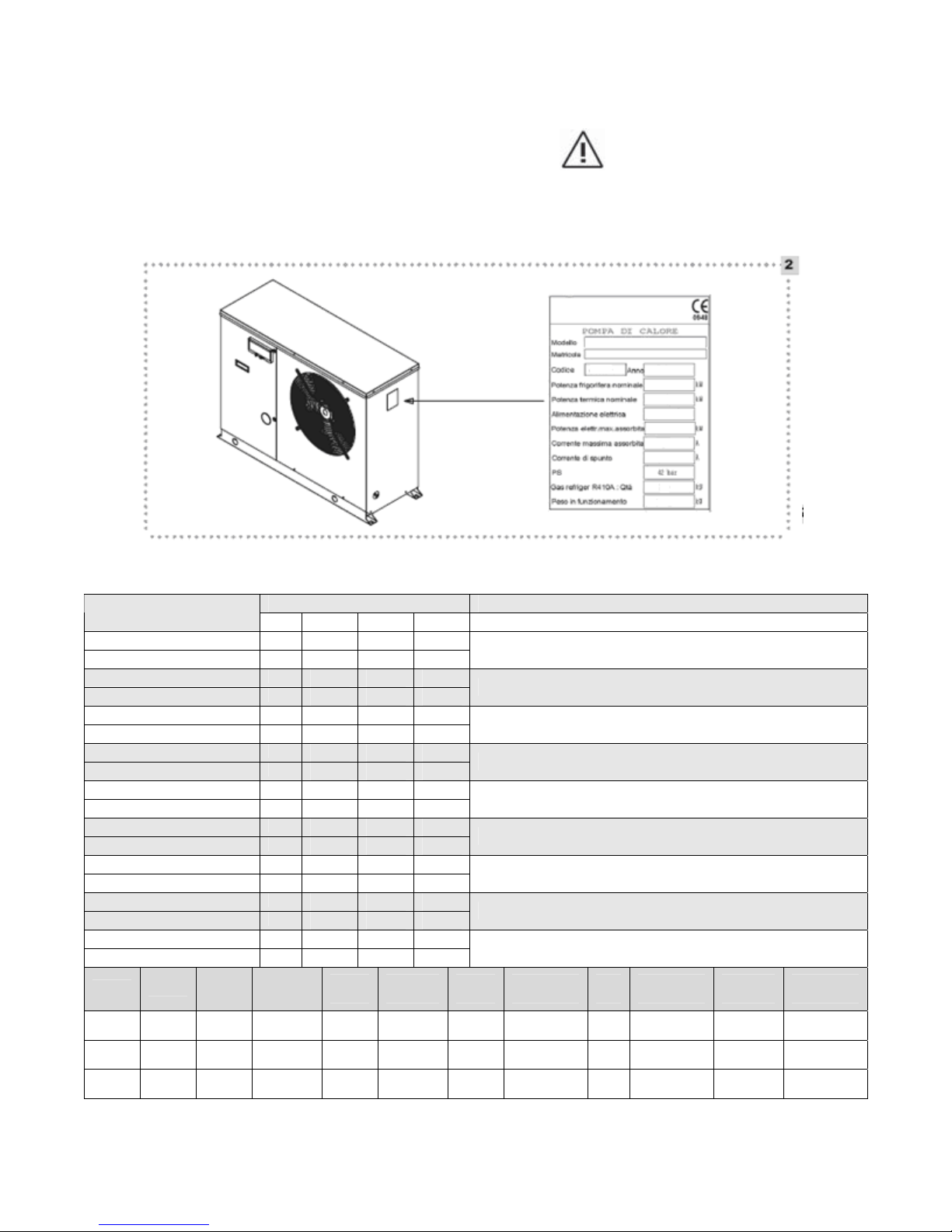
1.4 IDENTIFICATION
The Vokera ARIA unit can be identified by:
- Technical plate (fig. 2) It indicates the
technical and performance data of the
unit.
-
The tampering with, removal or
lack of the technical plate or anything
else that makes a certain product
identification impossible will make
correct maintenance or installation
operations more difficult.
1.5 TECHNICAL DATA
DESCRIPTION
Thermal power (1) kW
Absorbed power (1) kW
Thermal power (2) kW
Absorbed power (2) kW
Thermal power (3) kW
Absorbed power (3) kW
Thermal power (4) kW
Absorbed power (4) kW
Thermal power (5) kW
Absorbed power (5) kW
Thermal power (6) kW
Absorbed power (6) kW
Thermal power (7) kW
Absorbed power (7) kW
Thermal power (8) kW
Absorbed power (8) kW
Thermal power (9) kW
Absorbed power (9) kW
6HP
8HP
11HP
Empty
weight
110kg
112kg
164kg
SCRIPTIONODELLO / MODELS
Nominal
water
flow
1.0
m³/h
1.2
m³/h
1.6
m³/h
Diameter
hydraulic
fittings
¾”
¾”
Models
6HP 8HP 11HP
6.8 8.3 11.0
1.74 2.11 2.81
5.9 7.2 9.5
1.78 2.2 2.90
5.0 6.2 8.0
1.79 2.26 2.97
6.6 8.1 10.6
2.14 2.68 3.5
5.6 7.1 9.3
2.16 2.77 3.6
7.5 10.3 13.0
1.8 2.28 2.93
6.9 9.3 11.8
2.0 2.72 3.46
6.0 8.2 10.2
1.76 2.34 3.01
5.3 7.1 9.3
2.04 2.81 3.58
1”
Tank
capacity
16
litres
16
litres
36
litres
Electric
heater
3kW 230~ IP44 1 3.300 m³/h 58db (A) 1.7kg
3kW 230~ IP44 1 3.250 m³/h 58db (A) 1.9kg
6kW 230~ IP44 2 6.500 m³/h 62.8db (A) 2.7kg
(1) outside air d.b. + 7°C / w.b. + 6°C, water 35-30°C.
(2) outside air + 0°C, water 35 - 30°C
(3) outside air - 7°C, water 35 - 30°C
(4) outside air + 7°C, water 45 - 40°C
(5) outside air + 0°C, water 45 - 40°C
(6) outside air + 30°C, water 18 - 23°C
(7) outside air d.b. + 35°C / w.b. +24°C, water 18 -
23°C
(8) outside air + 30°C, water 7 - 12°C
(9) outside air d.b. + 35°C / w.b. +24°C, water 7 -
12°C
Power
voltage
Protection
rating
Axial
fan
Nominal
air flow
Noise
level
Refrigeration
load
Page 8
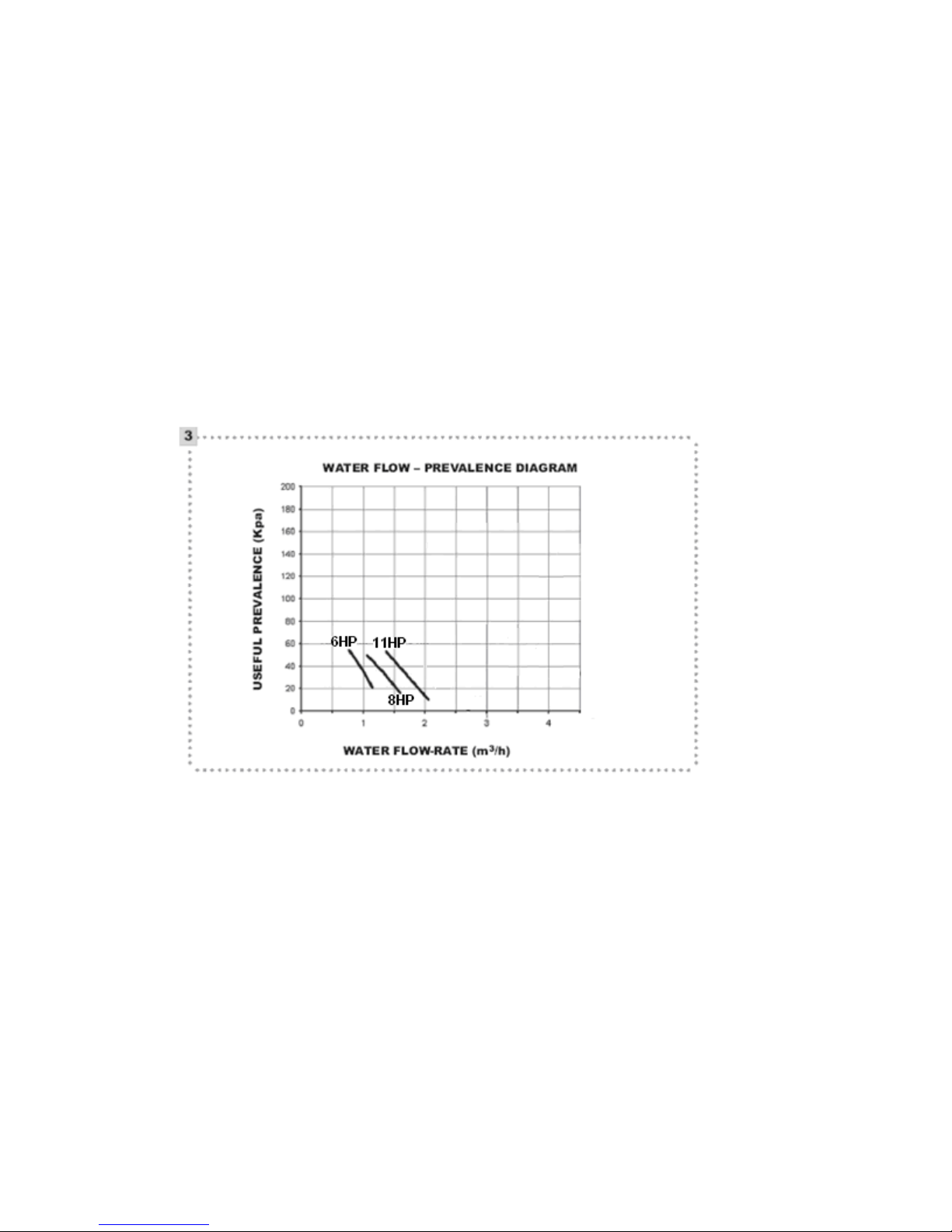
1.6 HYDRAULIC DATA
The following diagram (fig. 3) indicates the
residual prevalences with the nominal water flow
± 20%.
1.7 ACCESSORIES
The accessories indicated below must be
ordered separately
ACCESSORIES CODE
Remote control Kit 4014762
Anti-vibration supports Kit 4015360
Snow protection 6HP – 8HP 4014763
Snow protection 11HP - 4014764
Soft Start Kit 4014766
Hot water thermostat kit 4014767
1.5 kW single phase electric heater 4383270
1.7.1 Electric heater
The electric heater is integrated into the heat
pump to ensure continuity of service and is
inserted through a special plug into the storage
tank.
It is enabled to facilitate the compressor during
the start-up phase (it keeps the water at a set
temperature value (e.g. 30°C) and when the
atmospheric conditions become particularly
critical for correct machine operation (continual
frost caused by the low temperature and
excessive humidity).
Page 9

1.8 HEAT PUMP COOLING CIRCUIT
1 Fan 9 Plate exchanger
2 Finned battery (evaporator) 10 4 way-valve
3 Non-return valve 11 High pressure safety pressure-switch
4 Thermostatic valve (summer cycle) 12 Compressor
5 Thermostatic valve (winter cycle) 13 Liquids container
6 Filter 14 Low pressure safety pressure-switch
7 Fluid indicator 15 Pressure transducer
8 Flow switch 16 Safety valve
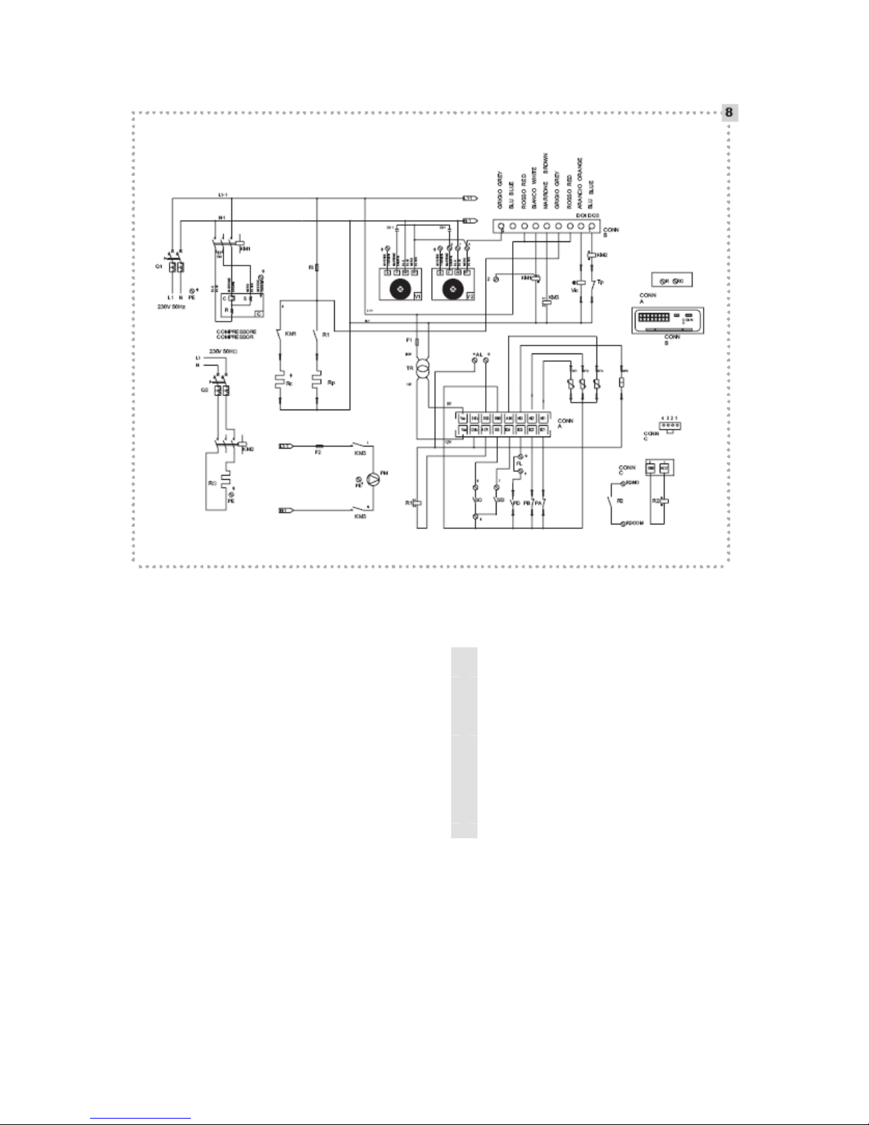
1.9 ELECTRIC PANEL AND WIRING
DIAGRAM
1.9.1 ARIA 6HP / 8HP Models
Factory installed components
CM Run condenser
CV1 Fan condenser
KM1 Compressor contactor
KM2 Resistance contactor
MI Control panel
Q1 Master circuit breaker
Q2 Support resistance circuit breaker
C Compressor
F1 Control safety fuse
F2 Pump safety fuse
F3 Resistance safety fuse
Conn.A Input terminal board
Conn.B Loads output terminal board
P Circulator
The units are equipped with an electric panel
consisting of the following components:
PD Flow switch
Tp Safety thermostat
TR Auxiliary circuits transformer
SP3 Pressure transducer
ST1 Temperature probe in exchanger inlet
ST2 Temperature probe in exchanger outlet
ST4 Outside air temperature probe
PA High pressure pressure-switch
PB Low pressure pressure-switch
VIC 4 way-valve
Rp Plate exchanger resistance
Rc Compressor cover resistance
Rs Support resistance
R1 / R2 Rp relay/boiler contact auxiliary relay
V1 Fan
Page 10
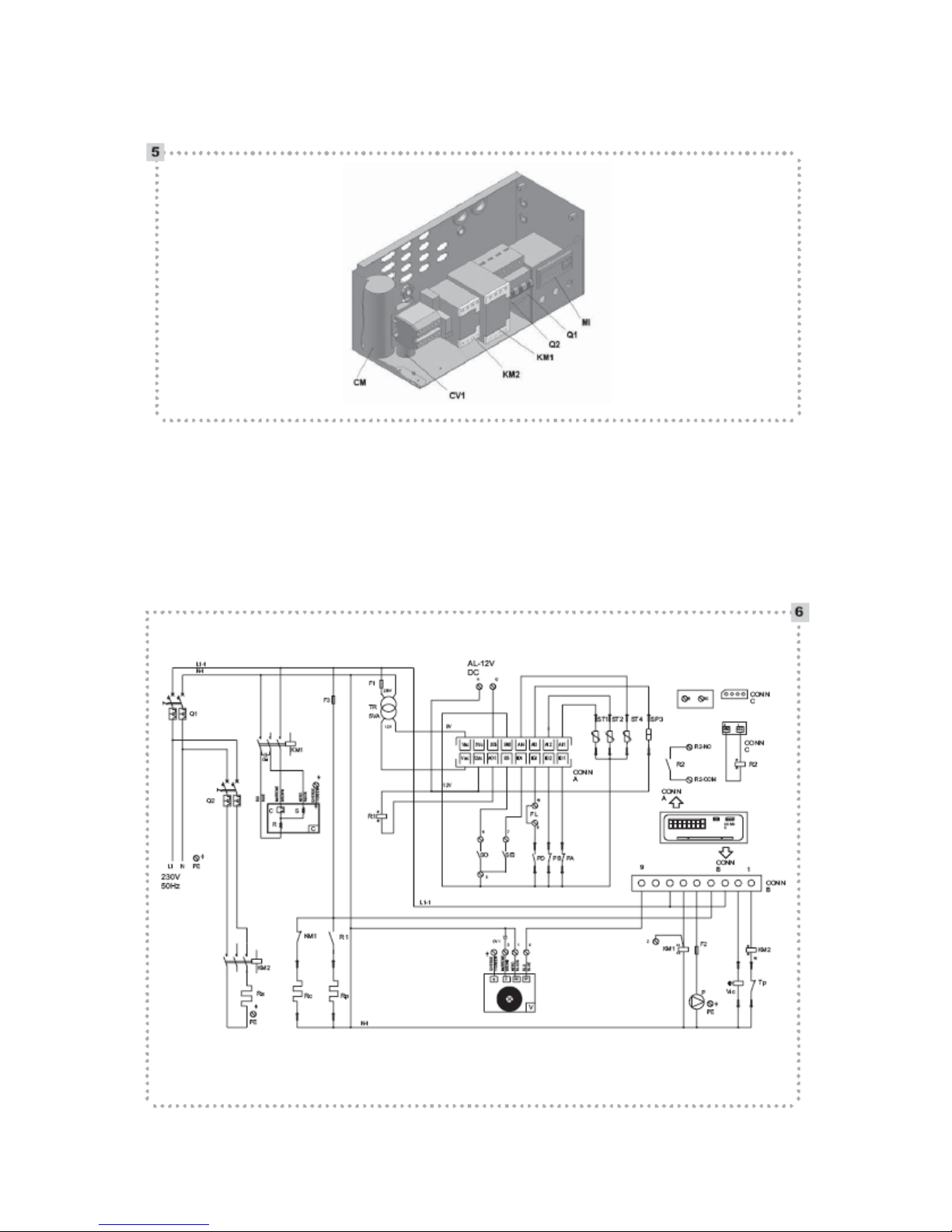
Components to mount on installation (not supplied with the unit)
AL Remote alarm signal (output 12V DC max 20mA)
FL Outside flow switch
SEI Remote SUMMER-WINTER switch
SO Remote ON-OFF switch
Page 11
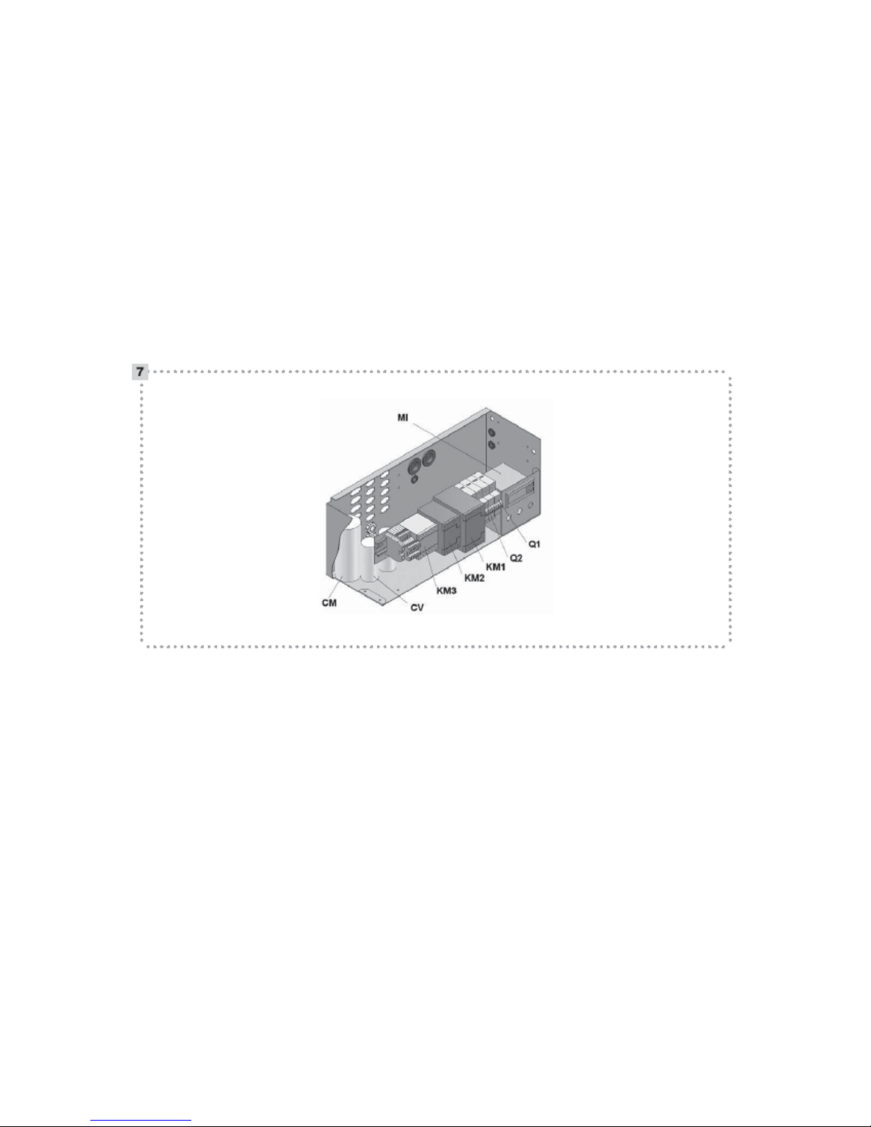
1.9.2 ARIA 11HP Model
Factory installed Components
CM Run condenser
CV1/2 Fan condenser
KM1 Compressor contactor
KM2 Resistance contactor
KM3 Pump contactor
MI Control panel
Q1 Master circuit breaker
Q2 Support resistance circuit breaker
C Compressor
F1 Control safety fuse
F2 Pump safety fuse
F3 Resistance safety fuse
Conn.A Inputs terminal board
Conn.B Loads output terminal board
P Pump / Circulator
PD Flow switch
Tp Safety thermostat
TR Auxiliary circuits transformer
SP3 Pressure transducer
ST1 Temperature probe in exchanger inlet
ST2 Temperature probe in exchanger outlet
ST4 Outside temperature probe
PA High pressure pressure-switch
PB Low pressure pressure-switch
VIC 4 way-valve
Rp Plate exchanger resistance
Rc Compressor cover resistance
Rs Support resistance
R1 / R2 Rp relay/boiler contact auxiliary relay
V1/2 Fan
Components to mount on installation (not supplied with the unit)
AL Remote alarm signal (output 12V DC max 20mA)
FL Outside flow switch
SEI Remote SUMMER-WINTER switch
SO Remote ON-OFF switch
Page 12
2.1 CONTROL PANEL
The control panel can be used to make all the
adjustments necessary for the heat pump
operation and display the values of the main
parameters and the alarms. It is located on the
front panel of the electric panel inside the unit
and is accessible through a flap positioned on the
inspection panel.
Display:
During normal operation it indicates the
temperature of the water returning from the
system.
It can also indicate the value of all the set
parameters and the code of any alarms.
Fig. 15
A
Alarm
B
Mode (Heat, Cool, etc....)
C
Economy (configurable)
D
Clock
E
Unit of measure
F
Navigation in the menu
G
Resources (Compressor, Fans, etc....)
Page 13

KEYS
Pressure with immediate
release
Scrolls the items in the
menu, increases the values
of the parameters
Scrolls the items in the
menu, decreases the
values of the parameters
Manual alarm rearm
Symbol printed on
front panel
Prolonged pressure (if key
is suitably configured)
Defrosting request
Switching on/off of the unit
(and vice versa)
Access to machine status
menu (setpoint, AI, DI, DO,
hours completed, pump
hours, etc....), access to
submenus, access to
parameter value,
confirmation of parameter
value
Exit from menu, parameters
list, parameter value and
return to upper level
Accesses
programming
menu
SET
used for:
• Access to machine status menu
• Access to sub-menus
• Access to parameter value
• Confirmation of parameter value or exit
• prolonged pressure accesses the menu for the
selection of the fundamental display (if the key is
Accesses the fundamental
avail
Accesses operating
mode
Display configuration file
mode selection file
(Heat/Cool/Std-by)
configured for this function); with the up and
down keys the options present can be displayed
(with display based on the machine configuration)
and pressure on the “set” key confirms the
selection.
UP
used for:
Page 14

• scrolling up the display of files and parameters
• Increase of the parameter value (if in parameter
value modification)
• Prolonged pressure accesses the function
called manual defrosting (if the key is configured
for this function), only from fundamental display.
DOWN
used for:
• Scrolling down the display of files and
parameters
• Decrease of the parameter value (if in
parameter modification)
• Prolonged pressure switches the unit on/off
from fundamental display (if the key is configured
for this function)
operations by intervening on the control panel or
acting on the remote switch (if present).
To access the control panel, open the flap as
follows:
- Remove the locking screw (fig. 16 ref. A)
- Simultaneously press on points B (fig. 16 ref. B)
and lift the flap (fig. 16 ref. C)
When operations on the control panel are
completed:
- Close the flap and reposition the locking
screw.
After powering up the unit, “OFF” will appear
on the display.
ESC
used for:
• Exit from the menu, from the parameters list,
from the parameter value without saving the
value and return to the previous level. Prolonged
pressure from fundamental display (if the key is
configured for this function) accesses the file for
changing the mode; with the UP and DOWN keys
displays the modes present (with display based
on the machine configuration) and pressure on
the SET key to confirm the selection made.
SET
+ ESC simultaneously to
access the parameters, functions, password etc
files.
UP
+ DOWN simultaneously to
rearm alarms when present.
2.2 ACTIVATION AND DEACTIVATION
After the first start-up by the Vokera technical
service the ARIA heat pump is adjusted for
“automatic” operation and no other interventions
are necessary. Therefore the plant manager must
perform the ACTIVATION and DEACTIVATION
Press the
key to enable the machine in
stand-by, now the circulation pump should switch
on and the display will show the temperature of
water returning from the system.
Now proceed as follows:
2.2.1 Heating/cooling activation
To select the operating mode hold down the
key until the message “HEAT”, “COOL” or
“STBY” appears, according to the current
operating status of the controller.
Select with UP
function and confirm with the SET
or DOWN the HEAT
key.
Heating (WINTER CYCLE) -By selecting HEAT
the
symbol lights up.
Cooling (SUMMER CYCLE) -By selecting COOL
the
symbol lights up.
Page 15

2.2.2 Heating/cooling deactivation
Keep
pressed for a few seconds until the
message “COOL” or “HEAT” appears (cycle
enabled). Select with the
confirm with the SET
“STBY” key and
key; the symbol
lights up.
To change the Heating/Cooling operating
mode on the heat pump models, it is advisable to
call the Vokera technical service.
2.3 OPERATIONS PERFORMED WITH THE
REMOTE ON-OFF “SO” and SUMMERWINTER
“SEI” SWITCHES (IF PRESENT).
2.3.1 Cooling function
Activation
- Position the SUMMER-WINTER
remote switch (SEI) to “OFF”.
- Position the ON-OFF remote
switch (SO) to “ON”.
The warning LED on the control
panel lights up.
Deactivation
- Position the ON-OFF remote switch (SO) to
“OFF”.
The message “OFF” flashes on the
CONTROL PANEL.
In case of a power failure lasting more
than four hours, when power returns, keep the
unit powered but deactivated for at least eight
hours.
In case of a power failure lasting less than
four hours, when power returns, keep the unit
powered but deactivated for the same number of
hours that the power was out.
2.4 SHUTDOWN FOR LONG PERIODS
If the ARIA heat pump is not used for a long
period, the following operations should be
performed:
- From the control panel, deactivate the unit it
whichever mode it is operating in.
- Position the remote switch to “OFF” (if present)
After deactivating the unit:
- Deactivate the indoor terminal units by setting
the switch on each appliance to “OFF”.
- Set the system master switch to “OFF”.
- Close the water taps.
If there is a possibility that the outside
temperature falls below zero there is a risk of
freezing.
The hydraulic system MUST BE EMPTIED or
else antifreeze liquid (e.g. ethylene glycol) must
be added in the doses suggested by the
manufacturer of the liquid. It advisable to contact
the Vokera technical service.
The message “OFF” appears and
flashes on the CONTROL PANEL.
2.3.2 Heating function
Activation
- Position the SUMMER-WINTER
remote switch (SEI) to “ON”.
- Position the ON-OFF remote
switch (SO) to “ON”.
The warning LED lights up on the control
panel.
Deactivation
- Position the ON-OFF remote
switch (SO) to “OFF”.
To start the unit up again after a long
period of inactivity, contact the Vokera technical
service.
2.5 CLEANING
The only essential cleaning that the plant
manager needs to perform is on the outside
panels of the cooler; this should be done with a
cloth and soap and water. For persistent stains
damp the cloth with a solution of 50% methylated
spirit or a specific product in water. When the
cleaning is completed, carefully dry the surfaces.
Do not use sponges with abrasive
products or powder detergents.
Do not perform cleaning operations until
the unit has been disconnected form the mains
power supply by turning the master switch on the
system to “OFF”.
2.6 MAINTENANCE
Routine maintenance is indispensable to
maintain the efficiency, safety and reliability over
the years. This can be carried out every six
Page 16

months, for some interventions and annually
for
others, by a competent person or by the Vokera
technical service that is technically prepared and
authorised and always has original spare parts
available when necessary.
For installations close to the sea, perform
the maintenance interventions twice as often.
Before starting any maintenance
interve o cut off
ntion on the unit, it is compulsory t
the mains power supply by turning the double
pole master switch on the system to “OFF”
.
7 USEFUL INFORMATION
2.
Vendor:
................
...............................................................
.........
s
Addres
...............
................................................................
...............
Tel.
.....................................................................
..........
...............
Installer:
................
...............................................................
.......
.
Name
............
...................................................................
................
Address
...............
................................................................
...............
tel.
........................................................................
.......
................
Technical s
ervice and assistance:
..............................................
Name.
............
...................................................................
................
Address
...............
................................................................
...............
Dimensions (mm) 6HP 11HP
8HP
L (mm) 040 1240 1
H (mm) 805 1000
P (mm) 378 428
L1 (mm) 1100 1300
P1 (mm) 425 472
P2 (mm) 890 1040
tel.
...............................................................................
................
DATE INTERVENTION
2.8 RECEIVING THE PRODUCT
The ARIA heat pumps are delivered in a single
package on a wooden pallet, protected by
cardboard packaging and accompanied by:
- instruction manual
- warranty certificate
- label with bar code
- first start up
- spare parts list.
The instruction manual is an integral part
of the unit and it should be read and then kept
with care.
It is advisable to position the unit in the
place of installation before removing the
packaging.
Do not dump packaging materials in the
environment or leave them within reach of
children as they are potentially dangerous.
2.9 DIMENSIONS WITHOUT PACKAGING
See page 8 for the weights.
Return / inlet 3/4" 1"
(inch)
Reintegration 1/2" 1/2"
(inch)
• P2: Dimensions with snow protection
Page 17

2.10 DIMENSIONS WITH PACKAGING
Dimensions
(mm)
L (mm) 1140 1340
H (mm) 950 1150
P (mm) 480 540
6HP
8HP
11HP
2.11 HANDLING AND TRANSPORT
The handling and transport must always be
carried out with the unit in a horizontal position. If
a fork lift truck is used, insert two metal pipes in
the special holes in the base and use suitable
lifting means. If a crane is used, pass the ropes in
the upper part of the wooden base taking care
not to apply pressure on the unit (fig. 18).
It is advisable to position the unit in the place of
installation before removing the packaging.
When the packaging has been removed,
handling is done by inserting two metal pipes
(max diameter 33 mm, min thickness 3.2 mm) in
the special holes in the base and use suitable
lifting means.
The weight of the unit is unbalanced
towards the compressor side (electrical panel
side).
During transport, the unit must always be
kept in a vertical position.
Handling must be performed by qualified
personnel, adequately equipped and with tools
that are suitable for the weight of the unit.
Instructions for lifting
- Make sure that all the panels are well fixed
before moving the unit.
- Before lifting, check the weight of the unit on the
CE label.
- Use all the lifting points indicated, and only
those.
- Use ropes of equal length.
- Handle the unit with care and without jerky
movements.
Page 18

2.12 POSITIONING
The position of the ARIA appliances must be
decided by the system designer or by a suitable
expert and must consider both the purely
technical issues and any local legislation in force
which foresees special authorisations (e.g. urban
planning, building regulations, environmental
pollution etc.).
It is therefore advisable to obtain all necessary
authorizations before starting the installation.
The appliances must be:
- Positioned on a flat surface capable of
supporting the weight.
- Positioned on a slab that is sufficiently rigid and
that does not transmit vibrations to any rooms
that are adjacent or below.
It is advisable to place a rubber mat between the
appliance and the slab (hardness 60 shores,
thickness 10 mm) or use the antivibration damper
supports available as accessories.
The unit is designed to be installed outside and
must be placed in a safe area as shown in the
figure below.
The spaces indicated are necessary to avoid air
currents and allow normal cleaning and
maintenance operations.
It is advisable to avoid:
- installation in wells or enclosed areas
- obstacles or barriers that could cause the
recycling of expelled air
- installation in areas with aggressive
atmospheric conditions
- installation in narrow areas where the noise
level of the appliance could be amplified by
reverberations or resonance
- installation in areas subject to the accumulation
of dust, leaves or anything that could reduce the
efficiency of the appliance by obstructing the air
flow
- situations where the expulsion of air from the
appliance can penetrate into adjacent inhabited
areas through doors or windows, provoking
inconvenience to persons.
Page 19

Dimensions
(mm)
6HP
8HP
11HP
A 1000 1200
B 500 600
C 1000 1000
D 600 800
In the case of several appliances side by
side on the battery side, add up the safety
distances.
When the snow hood is present, recalculate the distances with the accessory
installed.
Do not position the appliances with the
inlet of the fan of the first towards the finned
battery of the second.
2.12.1 Fixing position of dampers
See figure 20 with the relative models.
Page 20

2.13 HYDRAULIC CONNECTIONS
The choice and installation of components must
be made by the installer who acts in accordance
with good technical code of practice and
legislation in force.
Before connecting the pipes, ensure that they do
not contains pebbles, sand, rust, waste or foreign
bodies that could damage the system.
Hydraulic diagram for connection to the system
- ARIA 6HP / 8HP (fig. 21)
- ARIA 11HP (fig. 22)
For the electrical connection of the 3-way
valves see the ACS thermostat kit instructions
Legend fig. 21/22
1 Pressure gauge 8 Air breather
2 Anti-vibration joint 9 Expansion tank
3 Interception valve 10 Temperature probe
4 Net filter 11 Load/Reintegration
5 Flow controller 12 Discharge tap
6 Pump 13 Calibration bypass
7 Safety valve 14 Flow switch
Page 21

Hydraulic connections must be completed by
installing:
- a 0.5 mm metallic net filter in inlet (system
return)
- a flow meter in outlet (inlet to the system) for
liquids to be sized and adjusted based on the
hydraulic characteristics of the system; to be
installed half-way along a horizontal straight pipe
section, at least 1 metre long.
REFERENCE VALUES
PH
Electrical conductivity
Chlorine ions
Sulphuric acid ions
Total iron
M alkalinity
Total hardness
Sulphur ions
Ammonia ions
Silicon ions
ppm = parts per million
- air breather valve in the highest parts of the pipelines;
- flexible elastic joints;
- interception valves;
- interception valves for chemical wash.
The calibration by-pass must be inserted
downstream of the machine for greater
adjustment of the system flow-rate and
prevalence.
Together with the flow regulator, installed on
board the machine, it must guarantee the correct
flow-rate of water in transit in the appliance (with
∆T minimum 4°C and maximum 6°C);
Special supply/particle reintegration
waters must be conditioned with suitable
treatment systems. The values shown in the table
can be considered as reference values:
6÷8
less than 200 mV/cm (25°C)
less than 50 ppm
less than 50 ppm
less than 0.3 ppm
less than 50 ppm
less than 50 ppm (5 °F)
none
none
Less than 30 ppm
obstruction, breakage and noise problems for
which the manufacturer accepts no responsibility.
The units are fitted with circulation pumps
as standard.
Install a load/reintegration system and a
unit discharge system to be connected in the
lowest part of the hydraulic circuit.
Systems with antifreeze or particular
legislative dispositions require obligatory water
disconnect devices. If filters, flow-meter and
dampers are not installed this can cause
The water flow-rate must be kept constant
during operation.
The water contained in the system must be
sufficient to prevent unbalances in the cooler
circuit operation (see tables on page 8).
Page 22

2.14 POSITION OF THE FIXINGS
M Inlet to the system
R return from the system
r water reintegration
2.15 ELECTRICAL CONNECTIONS
The ARIA heat pumps leave the factory
completely wired and only require connection to
the mains electrical supply and connection of the
flow-meter which must be done by qualified
personnel in compliance with legislation in force.
For all electrical connections, refer to the wiring
diagrams in this booklet.
The following checks are also recommended:
- Check that the characteristics of the mains
electric supply are adequate to the absorption
indicated in the electrical characteristics table
shown below, also considering any other
appliances in parallel operation.
- Check that the mains supply corresponds to the
nominal value +/- 10%.
For electrical connections use double
insulation cables.
It is compulsory:
- to use an double pole thermal magnetic master
switch to protect the power line
- to make an efficient earth connection.
It is forbidden to use the gas or water
pipes to make the earth connection.
The manufacturer is not responsible for
any damage caused by a lack of earth
connection or by the failure to observe the
indications in the wiring diagrams..
ATTENTION:
FOR THE SIZING OF THE POWER SUPPLY
LINE, IN ADDITION TO THE POWER VALUE
SHOWN IN THE TABLE ABOVE, ALSO
CONSIDER THE ELECTRICAL RESISTANCE
VALUE IN PAGE 8 (TECHNICAL DATA).
2.16 OUTSIDE CONNECTIONS AND
ELECTRICAL POWER CABLE INFEED
The appliance is supplied with suitable cable
clamps for the passage of the mains power
supply cables and the other electrical
connections.
- Insert the mains power supply cable in the
larger cable clamp
Page 23

- Insert the cables from outside, routing them
towards the electrical panel.
Avoid direct contact with the un-insulated
copper pipes and with the compressor.
It is forbidden to insert the electrical
cables from the appliance in positions not
specified in this manual.
THE APPLIANCE MUST ALWAYS BE
ELECTRICALLY POWERED TO ALLOW A
CORRECT PRE HEATING OF THE
COMPRESSOR OIL. IT IS COMPULSORY TO
KEEP THE APPLIANCE POWERED FOR AT
LEAST 8 HOURS BEFORE THE FIRST STARTUP.
The electrical panel with the connection terminal
board is situated inside the appliance, in the
upper part of the technical area dedicated to
circuit components.
Before starting
operations, set the master switch on the system
to “OFF”.
To make the electrical connections:
- Unscrew the four screws on the inspection
panel (fig. 26 ref. A)
- Remove the panel (fig. 26 ref. B)
- Set the master switch A to “OFF” (fig. 26 ref. C)
- Insert the main power supply cable in hole
(fig. 26 ref. D) and the outside connection cables
in hole (fig. 26 ref. E).
Page 24

- Make the connections as indicated in figure 27
FL Outside flow switch
SEI Remote summer winter switch
SO Remote ON-OFF switch
AL Remote alarm signal (output 12V DC - max
20mA)
When the connections are completed, block the
cables with the cable clamps, turn the master
switch to ON and remount the inspection panel
with the special fixing screws.
Page 25

2.17 LOADING AND EMPTYING THE SYSTEM
2.17.1 Loading
Check that the gaskets are watertight.
- Before starting the loading set
the master switch on the system to “OFF”.
- Check that the discharge taps on the unit and
the system are all closed.
- Open all the breather valves on the unit, on the
system and on the relative terminals.
- Open the system interception devices.
- Start filling by slowly opening the system water
filling tap (fig. 28 ref. A) positioned outside the
unit.
- When water starts coming out of the breather
valves, close them and continue filling until
reaching the pressure envisaged for the system.
It is advisable to repeat this operation
after the unit has been functioning for a few hours
and then periodically check the pressure in the
system. The reintegration must be carried out
with the machine switched “OFF” (pump “OFF”).
The system must be loaded to a pressure
of between 1 and 2 bar that can be checked on
the pressure gauge on the unit.
2.17.2 Emptying.
Page 26

- Before starting the emptying set
the master switch on the system to “OFF”.
- Check that the system water reintegration/
loading tap is closed (fig. 28 ref. A)
- Open the inspection panel on the front of the
unit.
- For the 11HP model open the by-pass valve (to
be installed downstream of the machine), the unit
discharge tap, the discharge taps on the system
and all the breather valves.
- For models 6HP and 8HP open the two
discharge taps on the unit, the system discharge
taps and all the breather valves.
If the system contains antifreeze, it must
not be freely emptied because it is a pollutant.
It must be collected and eventually re-used.
3 ECHNICAL SERVICE
T
3.1 RECOMMENDED OP
ERATING
CONDITIONS
For perfect ope
ration of the unit, the advisable
conditions must be respected:
PERATING
O
CYCLE
OUTLET
WATER T
EMP.
OUTSIDE AIR
TEMP
min. max. in. max. m
Cooling
Heating
+7°C +18°C 15°C +42°C
+35°C +45°C -15°C +25°C
3.2 LIMIT OPERATING CONDITIONS
operate within the area “A “.
It is possible to operate in the area “B”, by
modifying the operating parameters of the unit.
Do not operate outside areas “A” and “B”.
able to For perfect operation of the unit, it is advis
Page 27

3.3 PREPARATION FOR THE FIRST
TARTING UP
S
The first starting up of the unit must b
e carried
out be the Vokera technical service.
Before starting up the unit, ensure that:
- All the safety conditions have been respected.
- The unit
has been suitably fixed to the support
surface.
- The safety area has been respected.
- The hydraulic connections have been ma
de
according to the instruction manual.
- The hydrau
lic system has been loaded and
purged.
- The interc
eption valves in the hydraulic circuit
are open.
- The elec
trical connections have been made
correctly.
- The voltage is within a 10
% tolerance of the
nominal value of the unit.
- The earth connection has been made correctly.
- All the ele
orrectly.
c
ctrical connections have been made
.4 FIRST START-UP
3
THE APPLIANCE MUST ALWAYS BE
ELECTRICALLY POWERED TO ALL
OW A
CORRECT PRE-HEATING OF THE
COMPRESSOR OIL. IT IS COMPULSORY TO
KEEP THE APPLIANCE POWERED FOR AT
LEAS
T 8 HOURS BEFORE THE FIRST START-
P.
U
Before activating the appliance, ensure that:
- Set the master switch on the
system to “OFF””.
- Remove the inspection panel (fig. 30 ref. A),
removing the four fixing screws (fig. 30 ref. B)
- Set the
master switch on the unit (fig. 31 ref. A)
to “ON”
- Set the master switch on the
system to “ON”.
- Check that the Display is on
and signals the
system return temperature.
- Keep the unit powered but not operating for at
least two hours to allow the oil in the compressor
to heat up.
- Switch on the unit.
For the correct position of the inside
components, refer to pages 10 to 12.
Page 28

3.6 ACTIVATION OF “SO” and “SEI”
CONTROL
PERFORM THE FOLLOWING OPERATIONS
FROM THE
CONTROL PANEL:
The operations described below must be carried
out with maximum attention to avoid
compromising the working efficiency of the unit.
If errors are made or if there are uncertainties
concerning the interpretation during the
operations,
WAIT FOR 15 SECONDS WITHOUT
PRESSING ANY KEY.
To activate the SO and SEI control, proceed as
follows:
- Power up the unit, setting the system master
switch and the unit master switch to “ON”.
If it is the first start-up, “OFF” will appear on the
display. In this case, press the
key to set
the machine in standby.
At this point the return temperature value will
appear on the display.
3.6.1 Setting the “SO” remote control (on off):
- Now press the
and keys
simultaneously to access the user parameters.
“Par” will appear on the display to indicate access
to the user parameters.
- Now press the
key to access the CF
menu.
- CF appears on the display to indicate the
remote controls parameter menu.
- Press the key and CF19 appears, with the
arrow key move to CF20, which indicates the
“SO” parameter, that is, remote summer/winter
change.
To set the remote SO control, just press
and move the value from 0 to -13 (minus 13);
then confirm with
the key.
- Press the key, until the display indicates the
temperature of the return water.
- Cut off the power to the machine to memorise
the value. Power it back up and check with the
key.
3.6.2 Setting the “SEI” remote control (change
summer – winter cycle):
- Now press the
and keys
simultaneously to access the user parameters.
“Par” appears on the display to indicate access to
the user parameters.
- Now press the
key to access the CF
menu.
- CF appears on the display to indicate the
remote controls parameter menu.
- When the
key is pressed CF19 appears,
that indicates the “SEI” parameter that is, remote
summer/winter change.
To enable the remote control, just press
and move the value from 0 to -14 (minus 14)
(using the arrows); then confirm with the
key.
- Press the
key, until the display indicates
the temperature of the return water.
3.7 ANOMALY SIGNALS
In case of a malfunction of the unit, codes will
appear on the control panel display, consisting of
letters and numbers alternating with the system
return temperature. Part of the alarms reset
automatically while others must be reset with the
manual intervention of the Manufacturers
Technical Service.
Page 29

DESCRIPTION
High pressure
Low pressure
Flow switch
Water circuit antifreeze
High water temperature
(< 60°C)
Clock fault error Er45
Clock to be adjusted error
Inlet temperature probe
Outlet temperature probe
Outside temperature probe fault Er68 automatic
SIGNAL RESET DISPLAY
Er01 manual
Er05 manual
Er20 manual
Er30 automatic
Er35
Er46
Er60 automatic
Er61 automatic
automatic
Condensation pressure probe
Configuration error
Compressor working hours
exceeded
Pump working hours exceeded Er85 manual
Alarms archive recordings
exceeded
3.7.1 Manual anomaly reset
After having cleared the cause that provoked the
anomaly, reset as follows:
Simultaneously press the UP
keys to reset the alarms.
Er75 automatic
Er80 automatic
Er81 manual
Er90 manual
3.8 ACTIVATION and DEACTIVATION of the
UNIT
and DOWN
To perform the ACTIVATION and
DEACTIVATION of the “COOLING” and
“HEATING” functions act on the CONTROL
PANEL installed on the machine, or on the two
REMOTE ON-OFF (SO) and SUMMER-WINTER
(SEI) SWITCHES if installed.
Page 30

Fig. 32
A Alarm
B Mode (Heat, Cool, etc....)
C Economy (settable)
D Clock
E Unit of measure
F Navigation in the menu icon
G Resources (Compressor, Fans, etc....)
To select the operating mode, hold down the
key until the message “HEAT”, “COOL” or
“STBY” appears, according to the current
operating status of the controller.
Select the HEAT function with UP
DOWN
and confirm with the SET
or
key.
Heating (WINTER CYCLE)
If the code “Er 20” appears on the display
during this first phase, proceed as follows:
- Check the water flow-rate and the connection to
terminals 9 and 10 of the flow-meter.
To access the control panel, open the
inspection flap (fig. 33 ref. A):
- Remove the locking screw
- Simultaneously press on points B (fig. 33 ref. B)
and lift the flap (fig. 33 ref. C)
When the operations on the control panel are
completed:
- Close the flap and reposition the locking
screw.
Activation
By selecting HEAT the
symbol lights up.
The change in the operating mode from
Heating to Cooling must only be carried out with
the temperature of inlet water to the exchanger
plate lower than 20°C.
The change in the operating mode from
Cooling to Heating must only be carried out with
the temperature of inlet water to the exchanger
plate higher than 20°C.
Limit the change in the operating mode to
once per day.
Page 31

Cooling (SUMMER CYCLE)
By selecting COOL the
symbol lights up.
Deactivation Heating/Cooling
Select the STBY option and confirm with the SET
3.9 OPERATIONS PERFORMED BY THE
ON-OFF “SO” and SUMMER-WINTER “SEI”
REMOTE
SWITCHES (IF PRESENT)
Cooling Function
Activation
key.
The
symbol lights up.
In case of a power failure lasting more
than four hours, when power returns, keep the
unit powered but deactivated for at least eight
hours.
In case of a power failure lasting less than
four hours, when power returns, keep the unit
powered but deactivated for the same number of
hours that the power was out.
-
- Position the SUMMER-WINTER
remote switch (SEI) to “OFF”
- Position the ON-OFF remote
switch (SO) to “ON”.
The
warning LED lights up on the control
panel.
Deactivation
- Position the ON-OFF remote switch
(SO) to “OFF”.
The message “OFF” flashes on the
CONTROL PANEL.
Heating Function
Activation
- Position the SUMMER-WINTER
remote switch (SEI) to “ON
- Position the ON-OFF remote
switch (SO) to “ON”.
The warning LED lights up on the
control panel.
Deactivation
- Position the ON-OFF remote
switch (SO) to “OFF”.
The message “OFF” flashes on the
CONTROL PANEL
Page 32

In case of a power failure lasting more
than four hours, when power returns, keep the
unit powered but deactivated for at least eight
hours.
In case of a power failure lasting less than
four hours, when power returns, keep the unit
powered but deactivated for the same number of
hours that the power was out.
Limit the change in the operating mode to
once per day.
3.10 DEFROSTING CHECK
To avoid the formation of ice on the finned
battery during the winter heating phase, each
machine is fitted with an automatic defrosting
device, managed by the microprocessor through
the pressure probes and timer.
During the defrosting procedure, the
symbol flashes on the control panel indicating the
defrosting status.
3.11 CONTROLS DURING AND AFTER THE
FIRST START-UP
When the start up is completed, check that:
- The current absorbed by the compressor is
less than that indicated in the technical data table
- The unit operates within the recommended
operating conditions (see page 45).
- The hydraulic circuit is completely purged of air
- The unit stops and the restarts.
3.12 LONG TERM SHUTDOWN
From the control panel, deactivate the heat pump
from whichever mode it is operating in.
After deactivating the unit:
- Set the remote switch to “OFF” (if present)
- Deactivate the indoor terminal units by setting
the switch on each appliance to “OFF”.
- Set the master switch on the system to “OFF”.
- Close the water taps.
If there is a possibility that the outside
temperature falls below zero there is a risk of
freezing.
The hydraulic system MUST BE EMPTIED or
else antifreeze liquid (e.g. ethylene glycol) must
be added in the doses suggested by the
manufacturer of the liquid.
If the unit is connected to a boiler in
parallel, during its operation, close the taps on
the unit. The temperature of the water circulating
in the heat pump must never exceed 60°C.
3.13 ROUTINE MAINTENANCE
Routine maintenance is essential to keep the
ARIA heat pump in perfect working order, from
both a functional and energy efficiency aspect.
The maintenance plan that the Vokera technical
service will perform annually, envisages the
following checks and operations:
- Check the expansion tank pressure (2 bar)
- Water circuit filling-up
- Air presence in the water circuit
- Working efficiency of safety devices
- Power supply voltage
- Electrical absorption
- Tighten electrical connections
- State of the compressor contactor
- Plate exchanger resistance efficiency
- Compressor resistance efficiency
- Cleaning of finned battery (*)
- Cleaning of fan grills
- Cleaning of condensation collection bowl (if
installed).
(*) every three months.
For appliances installed close to the sea, the
maintenance intervals should be halved.
During maintenance operations, it might be
necessary to remove the inspection panels on
the cooler. In this case, proceed as follows:
- Unscrew the fixing screws and remove the
panels.
- When the maintenance operations have been
completed:
- Remount the panes, proceeding in the reverse
order.
3.14 EXTRAORDINARY MAINTENANCE
3.14.1 Loading coolant gas
The ARIA heat pumps are pre-loaded with R410A
coolant gas and adequately tested in the factory.
In normal conditions they do not require any
intervention by the Manufacturers Technical
Service to check the coolant gas. However, over
time small leaks could develop in the joints
allowing the gas to leak and discharge the circuit,
causing a malfunction of the appliance. In this
case, the leaks must be found and repaired and
the cooling circuit must be washed with nitrogen
or with specific products and recharged as
follows:
- Empty and dehydrate the entire cooling circuit
using a vacuum pump connected both to the low
pressure and high pressure sockets until the
vacuum gauge shows 10 Pa. Wait at least 5
minutes and check that this value does not rise
over 200 Pa.
- Connect the coolant gas cylinder or a
recharging cylinder to the liquid line socket.
- Load the quantity of coolant gas, in liquid
phase, indicated on the technical plate of the unit.
- Always check the overheating and undercooling
values of the appliance which, in nominal
operating conditions must be respectively
between 6 and 10°C (OVERH), and maximum 2
°C (UNDERH). After a few hours of operation,
check that the flow indicator indicates a dry circuit
(dry - green).
If the operating conditions are different
from the nominal ones, this could give values that
are very different.
Page 33

The coolant must only be loaded in liquid
phase.
The test of the seal or search for leaks
must only be performed using coolant gas R
410A, possibly mixed with nitrogen, and checking
with an adequate leak detector.
It is forbidden to load the coolant circuits
with a coolant that is not R410A. Use of a coolant
different from R410A could seriously damage the
compressor.
Do not use oils other than those indicated.
The use of different oils could seriously damage
the compressor.
Characteristics
3.14.2 Compressor
The compressor is installed on the machine
already loaded with oil and sealed.
Normally it does not require any particular
interventions from the Vokera technical service.
3.15 DISPLAY AND CONTROL
PARAMETERS
3.15.1 Main parameters and variable
The control panel of the unit gives direct access
It is forbidden to use oxygen or acetylene
or other inflammable or poisonous gases as they
could cause explosions.
In case of breakages, if the compressor can be
repaired only use original oils.
DESCRIPTION SIGNAL FACTORY
DISPLAY VALUE
Summer Set
Point
Summer
Differential
Winter Set Point
Winter
Differential
Return Water
Temperature
Inlet Water
Temperature
Condensation
Pressure
Outside
Temperature
COOL
tr10
HEAT 40
tr11
Ai01
Ai02
Ai03
Ai04
to the main control parameters and the display of
some variable characteristics of the unit.
ADJUSTMENT
15
3
3
DISPLAY ONLY
Access to the various menus - parameters
The perfect operation of the unit is
obtained by respecting the factory regulations
and in any case, keeping within the permitted
ranges.
3.15.2Access and Modification of
Parameters
The unit must be electrically powered and the
display must show the temperature of water that
returns from the system, or the message “OFF”.
To access and eventually modify the parameters,
perform the following procedure:
- When the set
shown on the display to indicate the pressure and
temperature parameters menu.
Scroll with the
other parameter menus: A0 (output status), CL
(clock and date parameters), SP variable
parameters set-point, Sr (real non-variable
setpoints – display only).
57
Modification of heat and cool set-points
To modify the inlet water temperature set-point
(return from the system), proceed as follows:
key is pressed, Ai is
and keys to access
Page 34

- When the key is pressed, the first Ai
menu is shown on the display, with the
go to the SP menu and press the
key
key.
At this point, the message COOL appears, to
indicate the summer set point. To modify the
summer set point, press the key, and with
the
set value. To confirm, press the
Then press
and keys change the previously
key.
to exit.
To modify the winter set point, proceed as above.
When COOL appears, press the
access HEAT (winter set-point), press
key to
and change the parameter with the
and keys.
-
Modification of the temperature differentials
in heat and cool
To modify the temperature differential of the two
cycles, proceed as follows:
- Press the
and keys
simultaneously.
PAR is shown on the display.
- Now press the
key to access the CF
menu.
- Press the
to access tr10 that indicates the
key to access the tr menu, then
temperature differential for the summer cycle.
Press
again to access the parameter and
use the arrows keys to modify the differential
value.
Save and Exit
- To save the parameters, it is always
advisable to cut off the power supply
and then power back up. The display
will indicate the “return water
temperature”.
- To modify the temperature differential of the
winter cycle, go to the tr10 parameter (see
previous point).
- Press the
appears and with the
key until parameter tr10
key go to the tr11
parameter.
Now press the
key to access the
parameter and with the arrow keys change the
value of the differential.
- Press the
key, until the value of the value
of the return water appears on the display.
Save and Exit
Press the
Press
key to confirm.
to exit.
- To save the parameters, it is always advisable
to cut off the power supply and then power back
up.
- The display will indicate the “return water
temperature”.
3.16 TROUBLESHOOTING
In case of a malfunction of the unit, codes will
appear on the control panel display, consisting of
letters and numbers (e.g.Er01) alternating with
the system return temperature. Part of the alarms
reset automatically while others require a manual
intervention, pressing the UP and DOWN keys
(see page 30).
AUTOMATIC ANOMALY RESET
Page 35

When the alarm cause is cleared, the control
panel automatically returns to the normal
operating mode.
MANUAL AN O MALY RE SET
After having cleared the cause that provoked the
anomaly, reset by pressing simultaneously the
UP and DOWN keys.
ANOMALY
The
compressor
does not start
The
compressor
stops
following
safety device
intervention
Insufficient
Performance
Noisy
Compressor
CAUSE REMEDY
Power supply
voltage too low.
Circulator
broken or
clogged.
Electrical
connections
badly tightened.
Contactor coil
fault.
Broken
electronic card.
Condenser
peak failure
(single phase
version).
Compressor
failure.
LED phase
monitor “OFF”.
(three-phase
version).
Excessive inlet
pressure (Er01).
Low suction
pressure (Er05).
Insufficient flowrate or system
not purged
(Er020).
Circulator
broken or
clogged
(Er020).
Poor flow-meter
operation.
Compressor
motor fault.
High discharge
pressure.
Low suction
pressure.
Incorrect
thermostat
calibration.
Unit sizing.
Fluid return to
the compressor.
Inadequate
fixing.
Check
Replace the
compressor
Invert two
phases
Check
Replace the
component
Check
Check
Noises and
Vibrations
Low Discharge
Pressure
High Suction
Pressure
Low Suction
Pressure
Contact
between
metallic bodies.
Weak
foundations.
Loosened
screws
Low
condensation
air/water
temperature.
Fan adjustment
malfunction.
Insufficient
coolant load.
Compressor
discharge valve
leak.
High inlet water
temperature.
Thermostatic
expansion valve
broken or open.
Low inlet water
temperature.
Thermostatic
expansion valve
broken or
clogged.
Suction line
obstructed.
Clogged filter.
Evaporator
exchanger
clogged.
Excessive
quantity of
antifreeze in the
water circuit.
Check
Reset
Tighten the
screws
Check
Replace the
component
Check
Check
Page 36

Notes..
Page 37

Registered address:
Unit 7 Riverside Industrial Estate
enquiries@vokera.co.uk
www.vokera.co.uk
Sales, General Enquires
Vokèra Limited reserve the right to change
specification without prior notice
Consumers statutory rights are not affected.
A Riello Group Company.
Company Reg No: 1047779
Vokèra Ltd
Borderlake House
London Colney
Herts AL2 1HG
www.vokera.ie
T 0844 391 099
F 0844 391 0998
Vokèra Ireland
West Court, Callan
Co Kilkenny
T 056 7755057
F 056 7755060
 Loading...