

VOKERA AquaFlow Twin Installation & Servicing Instructions Manual
Supplied By www.heating spares.co Tel. 0161 620 6677
AquaFlow Single coil water cylinder
AquaFlow Twin Twin coil water cylinder
Installation
& Servicing
Instructions
THESE INSTRUCTIONS
TO BE RETAINED
BY USER
Vokèra is a licensed member of the Benchmark scheme
which aims to improve the standards of installation and
commissioning of domestic hot water systems in the UK.
Supplied By www.heating spares.co Tel. 0161 620 6677
PLEASE LEAVE THIS MANUAL WITH THE UNIT AFTER INSTALLATION
00142046
00
Aquaflow 150 - 200 - 250
-
AquaFlow Twin 210 - 250
INSTALLATION MANUAL
This manual gives detailed advice for installation and should be read carefully
prior to fitting any unvented unit. This Vokera Aquaflow cylinder must be installed
by a competent person and be installed in compliance with the Vokera Aquaflow
Installation and Maintenance Instructions, all current legislation, codes of practice
and regulations governing the installation of unvented hot water cylinders in force
at the date of installation.
Components supplied with the unit for site fitting
(See also page 2/3 for component list)
* Multibloc valve, includes pressure reducing valve, line strainer, balanced cold water take off, (for
shower or bidet only) check and expansion valve.
* Tundish.
* 1/2"F x 15 x 15 tee piece.
* Flexible hose.
* 3/4" x 22 mm Elbow / Drain Cock
* Commissioning valve, 1/2" BSP male.
* Motorized valve.
* Expansion vessel
Components factory fitted
* Immersion heater(s).
* Thermostats / thermal cut-out.
* Temperature and pressure relief valve.
Manual Handling Operations Regulations 1992 defines manual
handling as: "any transporting or supporting of a load (including the
lifting, putting down, pushing, pulling, carrying or moving thereof) by
hand or bodily force" The Regulations set no specific requirements
such as weight limits. However common sense still has to be used
based on an ergonomic approach for each individual
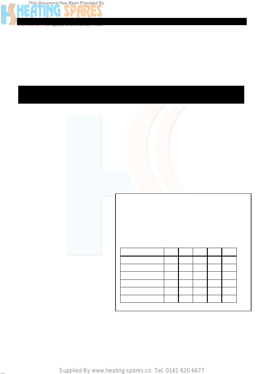
DIMENSION AND WEIGHTS TABLE 1
PRODUCT REF. 150 200 250 210T 250T
HEIGHT 900 1150 1600 1400 1600
DIAMETER 580 580 580 580 580
WEIGHT EMPTY 40 48 64 60 64
COIL RATING KW 12 26 26
UPPER COIL 12 12
LOWER COIL 12 26
Installation details
The Vokera unvented unit is designed for use with supply pressure up to 16 bar. For pressures
over 16 bar an additional pressure reducing valve must be fitted in the supply pipe to the unit. Wall
mounting brackets are available for Vokera Aquaflow unvented units 120-200 litres capacity.
Health and Safety
-1-
Supplied By www.heating spares.co Tel. 0161 620 6677
INDIRECT
2
2
RESET
1
1
2
3
3
4
1
4
2
RESET
5
1
1
1
1
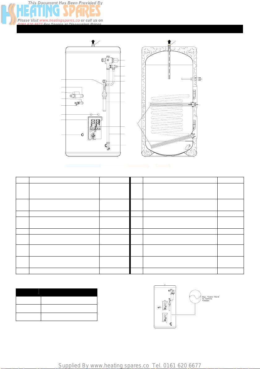
General Layout Fig: 1
9
3
4
16
1
8
1
2
4
15
1
3
113
RESET
RESET
4
4
2
2
1
1
2
2
2
10
5
6
17
7
7a
8
13
KEY Part No KEY Part No
1 Flow ¾" BSPF 10 Flexible Hose 202108
2 Return ¾" BSPF 11 Secondary Return ½”BSPF
3 Pressure Reducing Valve
510503 12 Commisioning Valve / Fitting
Includes Item 4
4 Check and Expansion Valve 510505 13 Elbow / Drain Cock 250445
5 Temperature and Pressure
550803 14 Cable Entry
Relief Valve
6 Tundish 219002 15 Electrical Box
7 Immersion Heater 71255 16 Tee Piece 250006
7A Thermostat Immersion Heater
Thermostat Cylinder
8 Cold Feed Tube
80400
80511
18 Motorised Valve Not Factory Fitted)
(Not Supplied See Table 2)
9 Hot Water Outlet 22mm
Fit ½"Fx½"Mx15mm Tee piece
supplied)
(½" MI Drain Cock)
17 Discharge Pipe (Not supplied)
9
(Not
250440
92000
Series Length of tube (ø22) mm
120 480 mm
150 585 mm
200 760 mm
-2-
TABLE 2
Supplied By www.heating spares.co Tel. 0161 620 6677
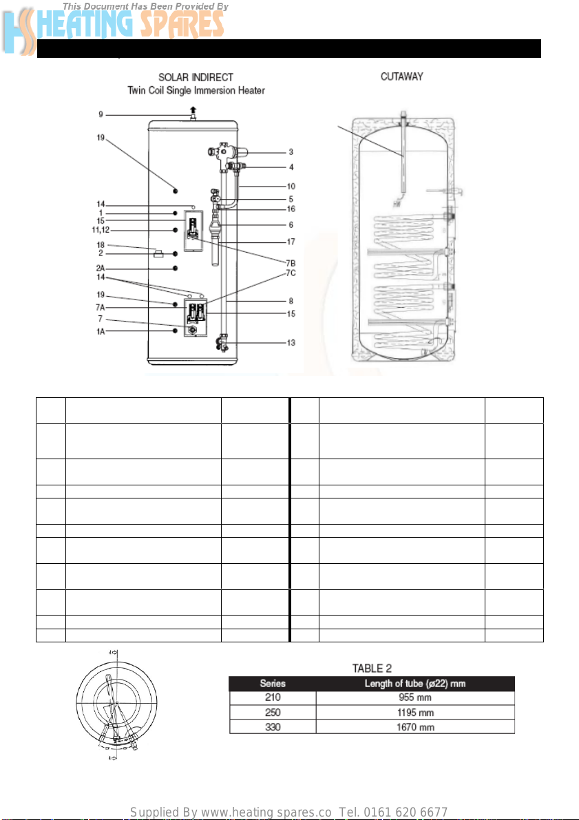
General Layout Fig: 1A
KEY Part No KEY Part No
1
Return ¾" BSP
1A
Return ¾" BSP
2
Flow ¾" BSP
2A
Flow ¾" BSP
3 Pressure Reducing Valve
Includes Item 4
4 Check and Expansion Valve 510505 13 Elbow / Drain Cock 250445
5 Temperature and Pressure
Relief Valve
6 Tundish 219002 15 Electrical Box
7
Immersion Heater
7A
Immersion Heater Thermostat
7B
Thermostat Boiler
7C
Thermostat Solar
8 Cold Feed Tube
(Not Supplied See Table 2)
9 Hot Water Outlet 22mm 19 Solar Sensor Bosses
20 Dip Pipe (removable)
10 Flexible Hose 202108
11 Secondary Return ½”BSPF
510503 12 Commissioning Valve / Fitting
550803 14 Cable Entry
71255
80020
80030
80030
18 Motorised Valve Not Factory Fitted)
-3-
20
Fit ½"Fx½"Mx15mm Tee piece
supplied)
(½" MI Drain Cock)
16 Tee Piece 250006
17 Discharge Pipe (Not supplied)
(Not
250440
92000

Supplied By www.heating spares.co Tel. 0161 620 6677
COLD WATER SUPPLY
1. To obtain the best performance from your Aquaflow unvented system it is advisable to feed
the unit with an uninterrupted supply.
Locate the water heater in a suitable po
2.
supply, discharge fittings and pipework. Also take into account
heaters and the commissioning valve.
Fit the combined male elbow / drain cock to cold supply point (13), so that the
3.
compression fitting is vertical.
Fit the commissioning valve (12) to the commissioning fitting.
4.
5. Fit both ½” male solar sensor pockets to the So
6. Fit the female outlet of the tee piece to the temperature and pres
horizontal connection facing right at approx. 45°.
Fit the tundish (6) to the tee piece using a short length of 15 mm copper tube.
7.
8. Fit the length of copper tube 22mm specified
9. Fit the pressure reducing valve (3) to the top of the copper tub e (see 7 above), so that the
black knob is facing right.
Connect the flexible hose to the 1/2" outlet of the expansion valve (4) and the horizontal outlet
10.
of the tee piece (see 5 above). Discard compression nut & ring.
If a balanced mains pressure cold water supply is required to a
11.
type only, ascending spray type requires type AA,AB or AD air gap), remove the blanking
cap from the pressure reducing valve (3) and connect to the shower or bidet cold supply.
(Major shower manufacturers advise fitting a mini expansion vessel in the balanced cold suppl y
pipework to accommodate thermal expansion and prevent tightenin g of shower controls)
the balanced cold connection to feed bath taps can reduce the flow available to the
unvented cylinder.
12. Before connecting the cold supply, flush the cold supply pipework of all flux and debris.
13. Connect the cold supply to the pressure reduction valve (Multibloc) (3).
sition to facilitate the installation of the cold water
access to the immersion
lar Sensor bosses (19).
sure relief valve (5) with the
in Table 2 to the cold feed elbow (see 3 above).
shower or
bidet (over rim
Using
Hot water supply
14. Connect the hot water supply pipe to the outlet (9). Ensure connection is water tight.
Secondary return
15. A secondary return facility is provided on all units. Fit a ½” F x ½” M x 15mm tee piece
between the commissioning valve (12) and the commissioning fitting. See also figure 4 on
page 16.
Discharge pipe
16. Connect the discharge pipe from the tundish (6.) This must have a continuous fall and be
fitted in accordance with The Building Regulations (see pages 5 and 12).
-4-
Supplied By www.heating spares.co Tel. 0161 620 6677
Primary flow & return and motorised valve
17. The boiler primary flow and return connections should be made to the unit. The motorised valve
must be fitted into the primary flow. The primary flow and return fittings are 3/4" BSP female.
18. For electrical connection of the motorised valve and immersion heater, please read Electrical
Installation Instructions. (Pages 7 – 11)
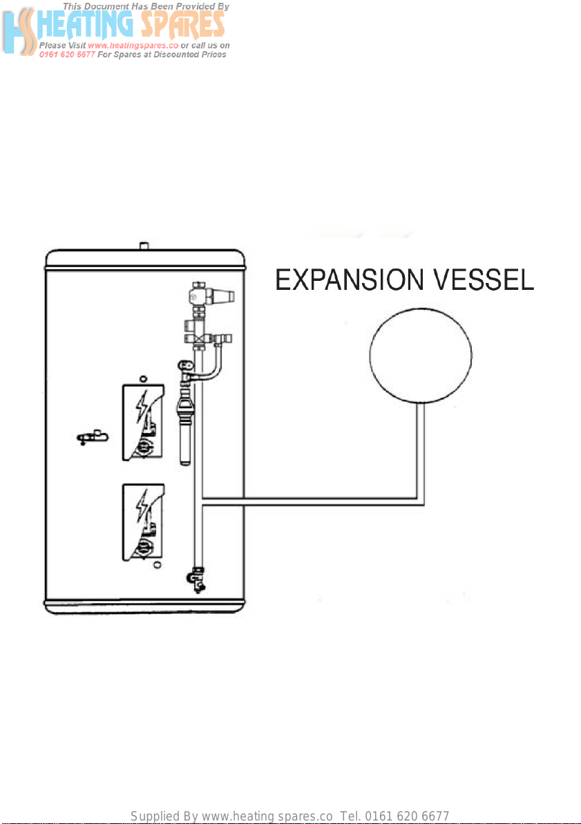
Expansion Vessel
19. Connect the expansion vessel to the cylinder as shown in the diagram below. The
vessel should be charged/pressurised to the same pressure as the PRV (Pressure Reducing
Valve).
Solar Primaries
20. The Solar flow and return connections should be made to the lower coil connections.
Temperature control from the Solar circuit is achieved using a differential solar controller.
The solar pump must be wired in series through the thermal cut-out on the Aquaflow
cylinder (see figure3 page 12).
21. If the solar primary circuit contains a mechanical shut-off device, ensure that a non return
valve in the circuit prevents thermal siphoning if the circulation is stopped. Care should be
-5-
 Loading...